The Continuous Casting of Steel in Vertical And Curved ...library.aimehq.org/library/books/Open...
8
• • Continuous Casting of Steel 21 The Continuous Casting of Steel in Vertical And Curved Mold Machines by Karl Georg Speith, Adolf Bungeroth, and Hans vom Ende The subject to be discussed here deals with the interesting problem of how to cast steel into a s trand most expediently . It has been shown by development that so far -there is only one practicable way for handl- ing steel according to the continuous casting process, i.e. by means of sliding molds , even though it s hould be possible in principal to apply other designs as well , such as rotat- ing rolls and chutes, endles s belts , or chains, etc. CONTINUOUS CASTING METHODS Vertica I Method Continuous casting of steel with sliding molds was first put into practice as a vertical casti ng pr oc- ess , us ing s traight, water-cooled molds . After additional cooling with spray water , the vertical strand pa ss es pinch rolls and the strand cutting and tilting machines. After being cut to length , the strand is then tilted from the verti cal in KARL GEORG SPEITH, ADOLF BUNGE- ROTH, and HANS yom EN DE are with the Mannesmann Forschungsinstitut GmbH, Duis- burg-Huckingen, Germany. the horizontal position and leaves the casting machine on a roller ta- ble. That is to say, not only cast- ing is taking place in the vertical position, but also subsequent cool- ing up to the final solidification of the strand including its transport and cutting as well. This leads to an enormous overall height of the whole plant building. It is also known that the overall heights of vertical continuous cast- ing plants grow considerably with increasing thickness of the strand . This is schematically shown in Fig. 1 for strands of 100 mm" (A 100) , 200 mm' (A 200) and 300 mm' (A 300). This picture holds on the premise that the strands be cast un- der comparable casting conditions , i.e. casting and cooling rates. Differ- ences in height up to 30 m between ca s ting mold and roller table are necessary, especially if large s trand s izes have to be cast. With increas- ing height, of course, difficulties re- garding plant layout and plant op- eration are increasing too, particu- larly when large heats have to be cast. This is true for all types of vertical plants, whether they are built as towers (Fig. 2), completely below floor level (Fig. 3), or some- LS • Length of sOlidification zone 30r- ....." 20t- t <I> :::t 70 ..... S • End of sOlidification A zoo : • • A 700 • • f77,om S fS " A 300 · • ' • • • • • • JS 0 ..... - 1 , ,,m,,,,,,,, """''' -;, 700mmx 700mm 200mm)(200mm 300mm)( 300mm (LS 5,5m) (LS '" 77,Om) (LS 76,5m) Fig. I-Vertical units (A) . Strand deformation by pinch roll pressure after complete solidifica- tion. /1 """""",,,,,,,,,, Fig. 2-The vertical casting plant of Man- nesmann AG, Grillo Funke Works at Gelsen- kirchen . where between. There have been many attempts, th€refore , to find solutions for reducing the heights of continuous casting installations. Bend-Straightening Method As a first step , bend- straightening machines were built, the first of which was successfully introduced to Barrow Steelworks (Great Brit- ain) in 1956 . The strand , after be- ' ing cast and cooled in its vertical pos ition, is bent aside below pinch roll level and runs circularly into the horizontal. There it has to be res traightened in case that larger s ections are to be cast. For s mall strand sizes, straightening is not ab- solutely necessary. Quite a few plants are working in thi s fa shion.
Transcript of The Continuous Casting of Steel in Vertical And Curved ...library.aimehq.org/library/books/Open...

• •
Continuous Casting of Steel 21
The Continuous Casting of Steel in Vertical And Curved Mold Machines
by Karl Georg Speith, Adolf Bungeroth, and Hans vom Ende
The subject to be discussed here deals with the interesting problem of how to cast steel into a strand most expediently. It has been shown by development that so far -there is only one practicable way for handling steel according to the continuous casting process, i.e. by means of sliding molds, even though it should be possible in principal to apply other designs as well, such as rotating rolls and chutes, endless belts, or chains, etc.
CONTINUOUS CASTING METHODS
Vertica I Method Continuous casting of steel with
sliding molds was first put into practice as a v ertical casting process , using straight, water-cooled molds. After additional cooling with spray water , the vertical strand passes pinch rolls and the strand cutting and tilting machines. After being cut to length, the strand is then tilted from the verti cal in
KARL GEORG SPEITH, ADOLF BUNGEROTH, and HANS yom EN DE are with the Mannesmann Forschungsinstitut GmbH, Duisburg-Huckingen, Germany.
the horizontal position and leaves the casting machine on a roller table. That is to say, not only casting is taking place in the vertical position, but also subsequent cooling up to the final solidification of the strand including its transport and cutting as well. This leads to an enormous overall height of the whole plant building.
It is also known that the overall heights of vertical continuous casting plants grow considerably with increasing thickness of the strand. This is schematically shown in Fig. 1 for strands of 100 mm" (A 100) , 200 mm' (A 200) and 300 mm' (A 300). This picture holds on the premise that the strands be cast under comparable casting conditions, i.e. casting and cooling rates. Differences in height up to 30 m between casting mold and roller table are necessary, especially if large strand sizes have to be cast. With increasing height, of course, difficulties regarding plant layout and plant operation are increasing too, particularly when large heats have to be cast. This is true for all types of vertical plants, whether they are built as towers (Fig. 2), completely below floor level (Fig. 3), or some-
LS • Length of sOlidification zone
30r
....." 20t
t ~.
.~ <I>
:::t 70 .....
S • End of sOlidification
Azoo : ~23,5m
••A700 •• f77,om
S fS ~
~
"
A 300·• ~300m '
••••••JS
0 .....- 1 ,,,m,,,,,,,, """''' -;, 700mmx 700mm 200mm)(200mm 300mm)( 300mm
(LS ~ 5,5m) (LS '" 77,Om) (LS ~ 76,5m)
Fig. I-Vertical units (A) . Strand deformation by pinch roll pressure after complete solidification.
/ 1 ~ """""",,,,,,,,,, ~+~,..,.,.,.,.,.,.
Fig. 2-The vertical casting plant of Mannesmann AG, Grillo Funke Works at Gelsenkirchen .
where between. There have been many attempts, th€refore, to find solutions for reducing the heights of continuous casting installations.
Bend-Straightening Method As a first step, bend-straightening
machines were built, the first of which was successfully introduced to Barrow Steelworks (Great Britain) in 1956. The strand, after be' ing cast and cooled in its vertical position, is bent aside below pinch roll level and runs circularly into the horizontal. There it has to be restraightened in case that larger sections are to be cast. For small strand sizes, straightening is not absolutely necessary. Quite a few plants are working in this fa shion.

22 Open Hearth Proceedings, 1966
Fig. 3-Model of the vertical casting machine at Donetsk, Russia .
By introducing the bend-straightening process to continuous cas ting, one cannot reduce that part of overall height which is due to solidification of the strand if bending is supposed to take place just after complete solidification. This is seen from Fig. 4, where the dotted lines indicate the lengths of the solidification zones. Comparing these schematic graphs with those of Fig. 1 it is evident that for varying strand sizes
...... .c:: .~
:'f. 10
(B100 : 100 mm', B200 : 200
LS • Lengln of s Olidi f ication zane
mm' cross-sections) distances between molds and pinch rolls are identical with those of the vertical cas ting process (AIOO, A200). Yet by removing the flame cutting machine from under the pinch rolls, and by removing the strand tilting equipment, the overall height can be reduced quite remarkably. It should be noted, however, that this method is safely applicable only for small and medium-sized strands up to 250 mm thick on the following
grounds: with increasing strand size casting rates go down; consequently any part of the strand stays in the solidification zone for a longer time, thus suffering from a loss in straightening temperature, even though with increasing strand size, cooling rates are decreasing too.
Circular Method Compared to vertical casting ma
chines, a further and very considerable reduction in height can be achieved by continuously casting steel in circular molds. This can be seen from the schematic graphs in Fig. 5, where ClOO, C200, and C300 stand for installations with strands of 100-, 200-, and 300-mm' crosssections, respectively. The circular mold process was first put into practice in the spring of 1963 after being developed independently by Mannesmann AG, Hilttenwerk Huckingen"', and by AG der von Moos' schen Eisenwerke at Luzern, Switzerland.' ·G By displacing the solidifi cation from the vertical strand position into the quadrant of a circular arc, the distance between mold and combined transport and straightening machine and the lingering time of the strand could be significantly reduced. There is no longer the limitation of strand size due to low straightening temperatures, as in the case of the bend-straightening process, because now straightening temperatures are higher.
ONE-STEP DEFORMATION OF A STRAND WITH STILL-LIQUID
INTERIOR All plants mentioned so far are
constructed so that there will be no deformation before complete solidification of the strand . It has been sta ted that after completion of solidification any strand can tolerate greater deformations without damage than before.' For instance, trials made in Huckingen with low carbon and medium carbon steels revealed that there will be no damage to strands cooled down from casting temperature to 800 · C at the surface,
LS - Lengtn of solidifical/on zon e
S • End Of solidificalion (A JOO ) S • End of solidification (A lOO) R • Bending radius Radius equals height of unit
(A zoo) (A ZOO}
8200 (8?IJO) : -78,Sm
••. C300 8 700 :
CZOO ; -7,77,om •- ~!-;o,om S~.R.S,Om \-7.5ry' \ .. R· 2,5m ·./ S s II It L-..,,~~=_O ~.~~~~--.~....~o;..,.,. -~ -~
700mm x 100mm (Ls-S,Sm)
200mm x 200mm (LS-71,Om) 700mm x 700mm
(LS -S,5m) 200mm x 200 mm
(Ls-n,Om) 300 mm x 300mm
(LS -76,Sm.)
Fig. 4-Vertical units with bending device by bending after complete solidification.
(6) . Strand deformation Fig. 5-Circular bow-casting machines (C). straightening after complete solidification.
Strand deformation by
30
Continuous Casting of Steel 23
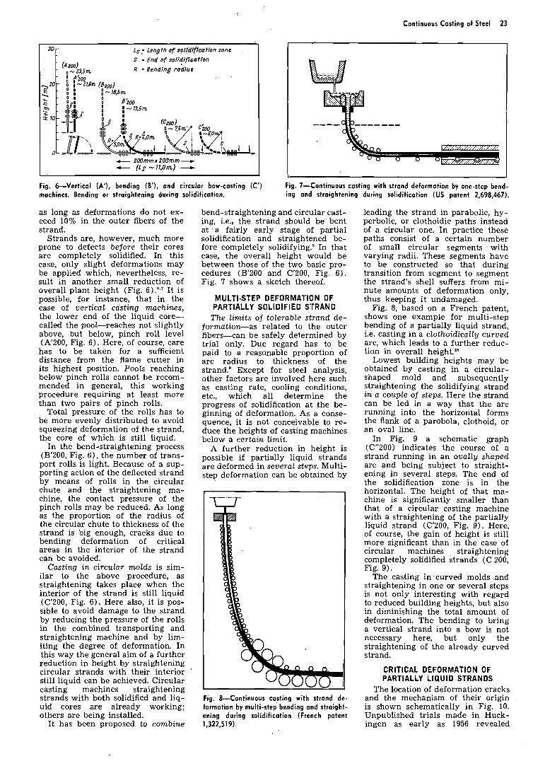
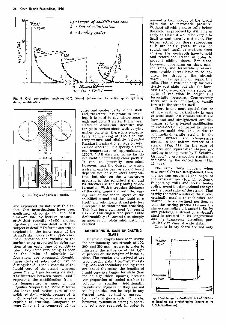
Fig. &Vertical (A'), bending (B'), and circular bow-casting (C') Fig. 7-Continuous costing with strand deformation by one-step bend- machines. Bending or straightening during solidification. ing and straightening during solidification (US patent 2,698,467).
30
20
* -s gr0-
as long as deformations do not ex- ceed 10% in the outer fibers of the strand.
Strands are, however, much more prone to defects before their cores are completely solidified. In this case, only slight deformations may be applied which, nevertheless, re- sult in another small reduction of overall plant height (Fig. 6) .'a7 I t is possible, for instance, that in the case of vertical ccisting machines, the lower end of the liquid core- called the pool-reaches not slightly above, but below, pinch roll level (A'200, Fig. 6). Here, of course, care has to be taken for a sufficient distance from the flame cutter in its highest position. Pools reaching below pinch rolls cannot be recom- mended in general, this working procedure requiring at least more than two pairs of pinch rolls.
Total pressure of the rolls has to be more evenly distributed to avoid squeezing deformation of the strand, the core of which is still liquid.
In the bend-straightening process (B'200, Fig. 61, the number of trans- port rolls is light. Because of a sup- porting action of the deflected strand by means of rolls in the circular chute and the straightening ma- chine, the contact pressure of the pinch rolls may be reduced. As long as the proportion of the radius of the circular chute to thickness of the strand is big enough, cracks due to bending deformation of critical areas in the interior of the strand can be avoided.
Casting in circular molds is sim- ilar to the above procedure, as straightening takes place when the interior of the strand is still liquid (C'200, Fig. 6). Here also, it is pos- sible to avoid damage to the strand by reducing the pressure of the rolls in the combined transporting and straightening machine and by lim- iting the degree of deformation. In this way the general aim of a further reduction in height by straightening circular strands with their interior '
still liquid can be achieved. Circular casting machines straightening strands with both solidified and liq- uid cores are already working; others are being installed.
I t has been proposed to combine
- Ls ,- Length of soliillficatfon zone
S - End of solidification (Azoo)
- , - 23,Sm R - Bending rodlus - : t i 0 0 - o I - 2 1 h ( 8 ~ ~ ~ ) - : : : - 18.5m - O ' : ~ i o o
- - -
0- m
bend-straightening and circular cast- ing, i.e., the strand should be 'bent at ' a fairly early stage of partial solidification and straightened be- fore completely solidifying.' In that case, the overall height would be between those of the two basic pro- cedures (B'200 and C'200, Fig. 6). Fig. 7 shows a sketch thereof.
c 200mmx 200mm -- e (Ls -11,On) -+
M U L T I S T E P DEFORMA'I ' ION O F PARTIALLY S O L I D I F I E D S T R A N D
The limits of tolerable strand de- formation-as related to the outer fibers-can be safely determined by trial only. Due regard has to, be paid to a reasonable proportion of arc radius to thickness of the strand.' Except for steel analysis, other factors are involved here such as casting rate, cooling conditions, etc., which all determine the progress of solidification at the be- ginning of deformation. As a conse- quence, it is not conceivable to re- duce the heights of casting machines below a certain limit.
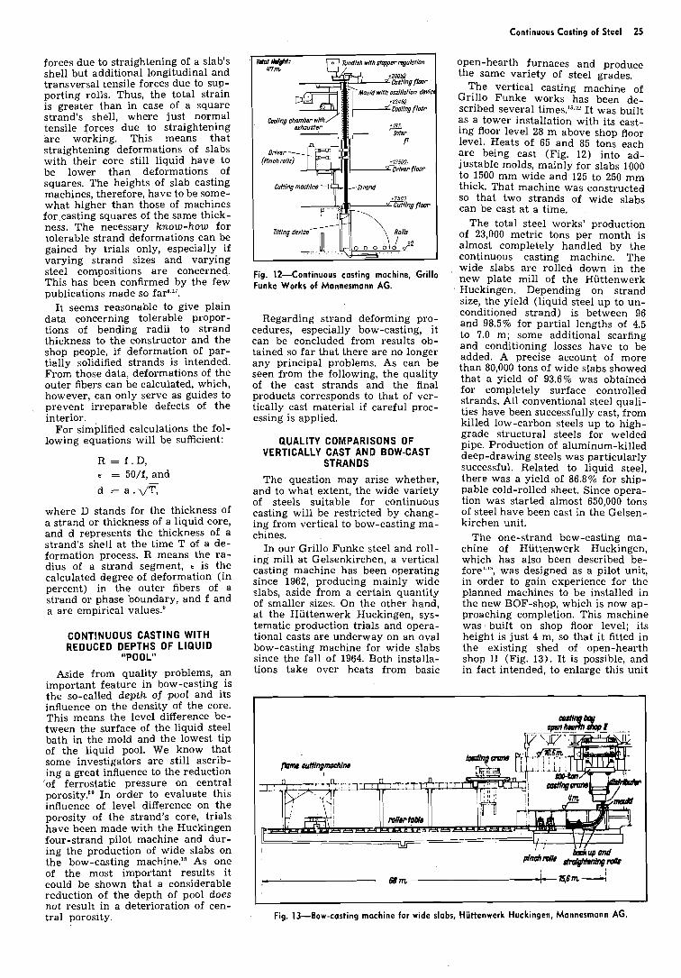
A further reduction in height is possible if partially liquid strands are deformed in several steps. Multi- step deformation can be obtained by
Fig. 8-Continuous casting with strand de- formation by multi-step bending and straight- ening during solidification (French patent 1,322,519).
leading the strand in parabolic, hy- perbolic, or clothoidic paths instead of a circular one. In practice these paths consist of a certain number of small circular segments with varying radii. These segments have to be constructed so that during transition from segment to segment the strand's shell suffers from mi- nute amounts of deformation only, thus keeping it undamaged.
Fig. 8, based on a French patent, shows one example for multi-step bending of a partially liquid strand, i.e. casting in a clothoidically curved arc, which leads to a further reduc- tion in overall height.1°
Lowest building heights may be obtained by casting in a circular- shaped mold and subsequently straightening the solidifying strand in a couple of steps. Here the strand can be led in a way that the arc running into the horizontal forms the flank of a parobola, clothoid, or an oval line.
In Fig. 9 a schematic graph (C"200) indicates the course of a strand running in an ovally shaped arc and being subject to straight- ening in several steps. The end of the solidification zone is in the horizontal. The height of that ma- chine is significantly smaller than that of a circular casting machine with a straightening of the partially liquid strand (C'200, Fig. 9) . Here, of course, the gain of height is still more significant than in the case of circular machines straightening completely solidified strands (C 200, Fig. 9).
The casting in curved molds and straightening in one or several steps is not only interesting with regard to reduced building heights, but also in diminishing the total amount of deformation. The bending to bring a vertical strand into a bow is not necessary here, but only the straightening of the already curved strand.
CRIT ICAL D E F O R M A T I O N O F PARTIALLY L I Q U I D S T R A N D S
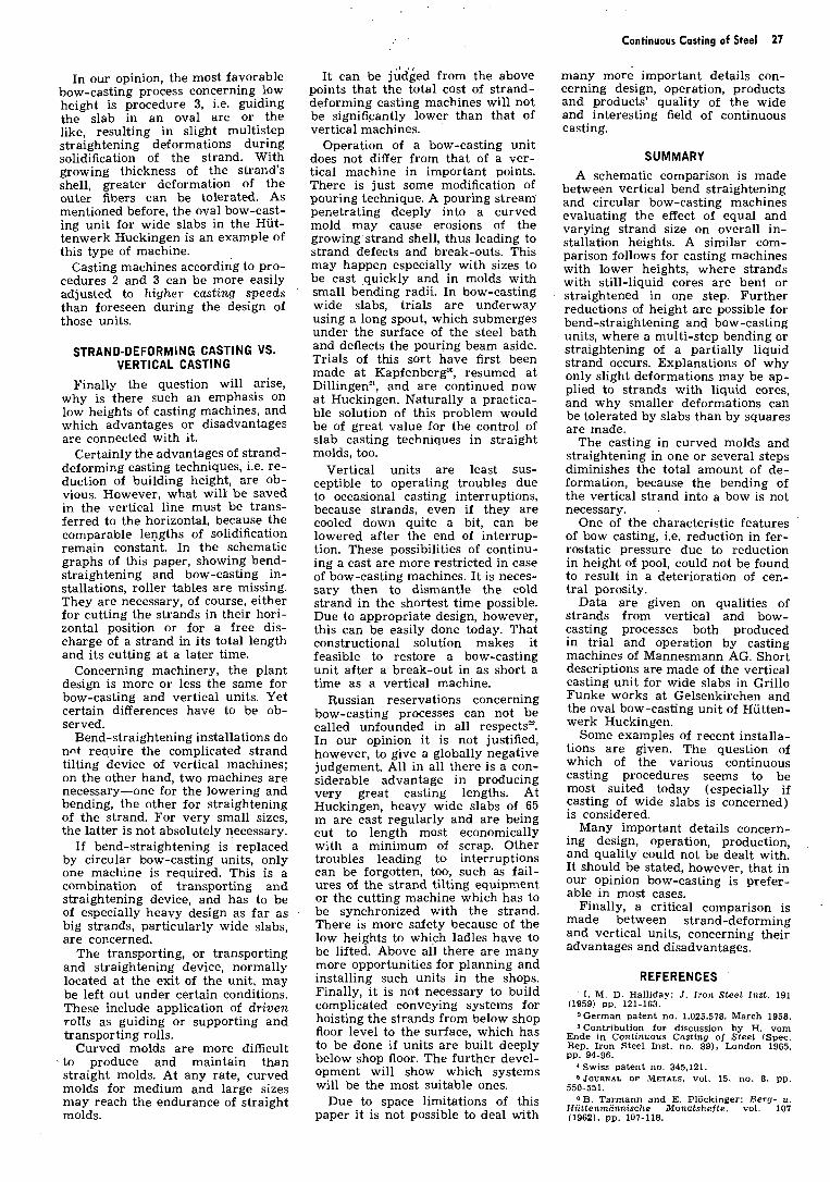
The location of deformation cracks and the mechanism of their origin is shown schematically in Fig. 10. Unpublished trials made in Huck- ingen as early as 1956 revealed
24 Open Hearth Proceedings, 1966
L s - Length of solidification zone S - End of solidification
R = ~ e n d l n g radius
4- ZOOmm x ZOOmm + t- (Ls - 71,Orn)
Fig. 9-Oval bow-casting machines (C"). Strand deformation by multi-step straightening during solidification.
outer and cooler parts of the shell and, therefore, less prone to crack- ing. It is hard to say where zone 2 ends and zone 3 starts. It has been stated in American literature that for plain carbon steels with varying carbon contents, there is a suscepti- bility to cracking at about solidus temperature and slightly below.'"" Russian investigations made on mild carbon steels in 1965 specify a criti- cal temperature of approximately 1350°C." All data gained so far do not yield a completely clear picture. It can be generally concluded, however, that the degree to which a strand can be bent or straightened depends not only on steel composi- tion, but also on the temperature gradient in the solidified shell and its thickness at the beginning of de- formation. With increasing thickness of the outer zones and with decreas-
Fig. 10-Origin of pinch roll cracks. ing size of the inner layers of the solidified strand and the liquid core itself, any solidifying strand gets less
and explained the nature of this de- susceptible to deformation cracking. fect. Our investigations have been This has been confirmed by recent confirmed-obviously for the first trials at Huckingen. The permissible time-in 1960 by Russian research- deformability of a strand rises steeply ers." Just recently (1965) another as soon as complete solidification is Russian ~ublication dealt with this reached. subject in detail." Deformation cracks originate in the inner parts of the CONDITIONS I N CASE OF CASTING strand's skin. close to the liauid core. SLABS - .-. - - ~ ~
their formahon and vicinity to the Schematic graphs have been shown surface being promoted by deforma- for continuously cast strands of 100, tions at an early time of solidifica- 200. and 300 mm2 square, in order to tion. They come into being as soon as the limits of tolerable de- formations are surpassed. Roughly three zones of solidification can be distinguished: zone 1 consists of the liquid core of the strand, whereas zones 2 and 3 are forming its shell. The interface between zones 1 and 2 represents the solidification front- its temperature is more or less liquidus temperature. Zone 2 forms the inner and hotter part of the solidified shell, which, because of its high temperature, is especially sus- ceptible to cracking. Compared to zone 2, zone 3 is composed of the
illustrate the influence of the type of process on the heights of installa- tions. The conclusions arrived at are true also for slabs. However, if cast- ing rates and secondary cooling rates are about the same, the lengths of liquid core are longer for slabs than for equally thick squares, because the proportion of cooled surface to volume is smaller. Additionally, rounds and squares, if they are not too big in size, can be kept in any desired track-vertical or curved- by means of guide rolls. For slabs, however, systems of strong support- ing rolls are required, in order to
prevent a bulging-out of the broad sides due to ferrostatic pressure. Without attaching those rolls below the mold, as proposed by Williams as early as 1942", it would be very dif- ficult to continuously cast slabs. The forces acting on those supporting rolls are fairly great. In case of rounds and small or medium sized squares, the pinch rolls have to hold and retard the strand in order to prevent sliding down. For slabs, however, depending on sizes, cast- ing rates, and ferrostatic pressure, considerable forces have to be ap- plied for dragging the strands through the system of supporting rolls. This is true not only for ver- tically cast slabs but also for bow- cast slabs, especially wide slabs, in- spite of reduction in height and ferrostatic pressure. Consequently there are also longitudinal tensile forces in the strand's shell.
There is one more special feature of bow casting, particularly in case of wide slabs. All strands which are bow-cast and straightened are dis- tinguished by a typical modification in cross-section compared to the re- spective mold size. This is due to longitudinal tensile strains in the upper surface and compressive strains in the bottom surface of a strand (Fig. 11). In the case of squares and square-like shapes, ac- cording to this picture by F. Schultz- Grunow'h cross-section results, as indicated by the dotted lines (Fig. 11, top).
The same thing happens when bow-cast slabs are straightened. Here the arching occurs at the edges of the cross-section (Fig. 11, bottom). Supporting rolls and straightening rolls prevent the dimensional changes on the broad sides of the strand. That is why the narrow sides of the strand, originally parallel to each other, are shifted into an inclined position, so that the casting profile assumes the shape resembling a trapezoid. So, by straightening, a strand or a strand's shell is stressed in its longitudinal and its transverse direction, par- ticularly in case of wide slabs.
That is to say there are not only
Fig. 11-Change in cross-sections of squares by bending and straightening (according to F. Schultz-Grunow).
forces due to straightening of a slab's shell but additional longitudinal and transversal tensile forces due to sup- porting rolls. Thus, the total strain is greater than in case of a square strand's shell, where just normal tensile forces due to straightening are working. This means that straightening deformations of slabs with their core still liquid have to be lower than deformations of squares. The heights of slab casting machines, therefore, have to be some- what higher than those of machines for casting squares of the same thick- ness. The necessary know-how for tolerable strand deformations can be gained by trials only, especially if varying strand sizes and varying steel compositions are concerned. This has been confirmed by the few publications made so fara,".
I t seems reasonable to give plain data concerning tolerable propor- tions of bending radii to strand thickness to the constructor and the shop people, if deformation of par- tially solidified strands is intended. From those data, deformations of the outer fibers can be calculated, which, however, can only serve as guides to
, prevent irreparable defects of the interior.
For simplified calculations the fol- lowing equations will be sufficient:
R = f . D , E = 50/f, and
d = a . d T ,
where D stands for the thickness of a strand or thickness of a liquid core, and d represents the thickness of a strand's shell at the time T of a de- formation process. R means the ra- dius of a strand segment, E is the calculated degree of deformation (in percent) in the outer fibers of a strand or phase boundary, and f and a are empirical values.'
CONTINUOUS CASTING W I T H REDUCED DEPTHS OF L IQUID
"POOL"
Aside from quality problems, an important feature in bow-casting is the so-called depth of pool and its influence on the density of the core. This means the level difference be- tween the surface of the liquid steel bath in the mold and the lowest tip of the liquid pool. We know that some investigators are still ascrib- ing a great influence to the reduction 'of ferrostatic pressure on central porosity."' In order to evaluate this influence of level difference on the porosity of the strand's core, trials have been made with the Huckingen four-strand pilot machine and dur- ing the production of wide slabs on the bow-casting machineF8 As one of the most important results it could be shown that a considerable reduction of the depth of pool does not result in a deterioration of cen- tral porosity.
Fig. 12-Continuous casting machine, Grillo Funke Works of Mannesmann AG.
Regarding strand deforming pro- cedures, especially bow-casting, it can be concluded from results ob- tained so far that there are no longer any principal problems. As can be seen from the following, the quality of the cast strands and the final products corresponds to that of ver- tically cast material if careful proc- essing is applied.
QUALITY COMPARISONS OF VERTICALLY CAST AND BOW-CAST
STRANDS
The question may arise whether, and to what extent, the wide variety of steels suitable for continuous casting will be restricted by chang- ing from vertical to bow-casting ma- chines.
In our Grillo Funke steel and roll- ing mill at Gelsenkirchen, a vertical casting machine has been operating since 1962, producing mainly wide slabs, aside from a certain quantity of smaller sizes. On the other hand, at the Huttenwerk Huckingen, sys- tematic production trials and opera- tional casts are underway on an oval bow-casting machine for wide slabs since the fall of 1964. Both installa- tions take over heats from basic
Continuous Casting of Steel 25
open-hearth furnaces and produce the same variety of steel grades.
The vertical casting machine of Grillo Funke works has been de- scribed several times.ls." I t was built as a tower installation with its cast- ing floor level 28 m above shop floor level. Heats of 65 and 85 tons each are being cast (Fig. 12) into ad- justable molds, mainly for slabs 1000 to 1500 mm wide and 125 to 250 mm thick. That machine was constructed so that two strands of wide slabs can be cast at a time.
The total steel works' production of 23,000 metric tons per month is almost completely handled by the continuous casting machine. The wide slabs are rolled down in the new plate mill of the Hiittenwerk Huckingen. Depending on strand size, the yield (liquid steel up to un- conditioned strand) is between 96 and 98.5% for partial lengths of 4.5 to 7.0 m; some additional scarfing and conditioning losses have to be added. A precise account of more than 80,000 tons of wide slabs showed that a yield of 93.6% was obtained for completely surface controlled strands. All conventional steel quali- ties have been successfully cast, from killed low-carbon steels up to high- grade structural steels for welded pipe. Production of aluminum-killed deep-drawing steels was particularly successful. Related to liquid steel, there was a yield of 86.8% for ship- pable cold-rolled sheet. Since opera- tion was started almost 650,000 tons of steel have been cast in the Gelsen- kirchen unit.
The one-strand bow-casting ma- chine of Huttenwerk Huckingen, which has also been described be- fore","', was designed as a pilot unit, in order to gain experience for the planned machines to be installed in the new BOF-shop, which is now ap- proaching completion. This machine was , built on shop floor level; its height is just 4 m, so that it fitted in the existing shed of open-hearth shop I1 (Fig. 13) . It is possible, and in fact intended, to enlarge this unit
Fig. 13-Bow-casting machine for wide slabs, Hiittenwerk Huckingen, Mannesmann AG.

26 Open Hearth Proceedings, 1966
Fig . 14-0vally shaped slab guiding device Mannesmann AG.
into a two-strand machine. Depending on the casting program and time required for changing to other strand sizes, up to 25,000 tons of slabs can be cast in a month, if there is one-strand operation and ladle weights are between 150 and 160 tons. Fig. 14 shows the ovally shaped strand guiding device under the curved mold. This design as an oval bow- casting unit is a prototype in many respects, since it is intended for slabs up to 2.1 m wide, where the strand is continuously straightened with increasing radii. The adjustability, successfully tried out on the vertical unit at Gelsenkirchen, was maintained in the bow-casting machine. It is not surprising that difficulties arose. The causes have been clearly determined, but their elimination requires some time. This has to be taken into account regarding the past production of that in stallation, which amounts to 150,000 tons, primarily slabs 1600 to 1800 mm wide and 200 mm thick. The yield of undivided slab related to li quid steel is between 97 and 98.5% . Taking into consideration cuttin,E( and scarfing losses, this results in 93 to 95% good s labs for the production of heavy and medium-sized plate and hot and cold-rolled strip.
Earlier experiences show that bow-casting is practicable for slabs bigger than 1500 mm wide, although with increasing width, difficulties are increasing considerably. Today the Huckingen machine produces slabs up to 2100 mm relia bly and satisfactorily . Its basic features of design will be taken over for the casting machines to be installed in the new BOF-shop at Huckingen. Comparing the final products made from wide slabs from the Gelsenkirchen
of bow-casting machine, Hiittenwerk Huckingen,
vertica l unit and the Huckingen oval bow-casting unit, it can be concluded that both casting procedures are equivalent, regarding casting technique and slab quality. This has been confirmed by results obtained elsewhere.
APPLICATION OF VARIOUS PROCESSES FOR SQUARE SIZES If applied properly, bow-casting
processes, including one- or mul tistep deforma tion of partially liquid strands. can yield the same good results as vertical casting. Producers of especially difficult steels will probably wish to remain on the safe side and therefore sti ll prefer vertical continuous casting. This attitude will be shared by those who suspect certain risks from the new types of processes. Incidentally, thi s was one of the reasons for building a mere vertical machine at Gelsenkirchen as la te as 1962.
Even today, bend-straigh tening, i.e. bending of a completely or partially solidified strand, can still be of interest, if small or medium~sized strands are to be cast with short transit times and high straigh tening temperatures.
However, if larger sizes are also to be cast, p!'eference will be given to a mere circular bow-cas ting with straightening of the strand after complete solidification. This holds for high-grade steels and high-quality specifications. The new circular bowcasting unit of Copperweld Steel Co. at Warren, Ohio, where high-grade carbon steels and alloy steels for structural purposes are being cast, may serve as an example. Another circular bow-casting machine is operated by Armco Steel Co. at Sand Springs, Okla. Here, ordinary carbon
steels are cast into small-sized billets. Straightening takes place when the strand core is s till liquid.
Today there are quite a few circular bow-casting machines straigh tening strands both after and before complete solidification. Sometimes it is not even possible to distinguish precisely between those two procedures. In the case of specific steel grades, if difficulties arise from straightening strands before complete solidification, it is possible to reduce the length of the pool and thus straighten the strands after complete solidification. Of course, this cannot be done without a reduction of casting rate.
APPLICATION OF VARIOUS CONTINUOUS CASTING PROCESSES
As mentioned before, for casting slabs , especially wide slabs, a sys tem of supporting and straightening rolls is required to keep the wide sides of the slab parallel to each other. Under these conditions there are principally three possibilities in bow -casting, so vertical casting will not be considered here. The three possi bili ties are:
I. Circular bow -casting including one-step straightening of a slab that is completely 01' almos t completely solidified;
2. Circular bow-casting with onestep straigh tening of slabs, the cores of which are still liquid; and
3. Bow-casting in an ovally or simi larly shaped mold, including multi-step straightening of slabs with their cores still liquid .
Casting wide slabs at higher rates requires fairly great building heights, even for the bow-casting machine. Th is is due to the fact that there are longer depths of pool and extremely low tolerable deformations for slabs compared to squares, if their casting speed and thickness are about the same.
Choosing the first procedure (onestep straightening of the completely solidified s trand) the comparatively long depth of pool has to be entirely distributed on a long, i.e. relatively high , quadrant of a circular arc. There is a certain maximum casting rate. Two examples of this type of installation are the circular bow casting machine of Atlas Steel Co. at Tracy (production of stainless steel) and the second unit of AG der Dillinger Hlitte for plain open hearth steels.
In the second procedure (circular bow-casting with one-step straight ening of partially liquid strands). the proportion of arc radius to thickness of the slab has to be very great because of the str ic tly reduced tensile strain tolerance. Despite this, this would lead to somewhat lower heights than procedure 1. We have not heard of any ins talla tion working exactly in that way.
Continuous Casting of Steel 27
In our opinion, the most favorable bow-casting process concerning low height is procedure 3, i.e. guiding the slab in an oval arc or the like, resulting in slight multistep straightening deformations during solidification of the strand. With growing thickness of the strand's shell, greater deformation of the outer fibers can be tolerated. As mentioned before, the oval bow-cast- ing unit for wide slabs in the Hiit- tenwerk Huckingen is an example of this type of machine.
Casting machines according to pro- cedures 2 and 3 can be more easily adjusted to higher casting speeds '
than foreseen during the design of those units.
STRAND-DEFORMING CASTING VS. VERTICAL CASTING
Finally the question will arise, why is there such an emphasis on low heights of casting machines, and which advantages or disadvantages are connected with it.
Certainly the advantages of strand- deforming casting techniques, i.e. re- duction of building height, are ob- vious. However, what will be saved in the vertical line must be trans- ferred to the horizontal, because the comparable lengths of solidification remain constant. In the schematic graphs of this paper, showing bend- straightening and bow-casting in- stallations, roller tables are missing. They are necessary, of course, either for cutting the strands in their hori- zontal position or for a free dis- charge of a strand in its total length and its cutting at a later time.
Concerning machinery, the plant design is more or less the same for bow-casting and vertical units. Yet certain differences have to be ob- served.
Bend-straightening installations do nnt require the complicated strand tilting device of vertical machines; on the other hand, two machines are necessary-one for the lowering and bending, the other for straightening of the strand. For very small sizes, the latter is not absolutely necessary.
If bend-straightening is replaced by circular bow-casting units, only one machine is required. This is a combination of transporting and straightening device, and has to be of especially heavy design as far as big strands, particularly wide slabs, are concerned.
The transporting, or transporting and straightening device, normally located at the exit of the unit, may be left out under certain conditions. These include application of driven rolls as guiding or supporting and transporting rolls.
Curved molds are more difficult . to produce and maintain than straight molds. At any rate, curved molds for medium and large sizes may reach the endurance of straight molds.
It can be jG'died from the above points that the total cost of strand- deforming casting machines will not be significantly lower than that of vertical machines.
Operation of a bow-casting unit does not differ from that of a ver- tical machine in important points. There is just some modification of pouring technique. A pouring stream penetrating deeply into a curved mold may cause erosions of the growing-strand shell, thus leading to strand defects and break-outs. This may happen especially with sizes to be cast ,quickly and in molds with small bending radii. In bow-casting wide slabs, trials are underway using a long spout, which submerges under the surface of the steel bath and deflects the pouring beam aside. Trials of this sort have first been made at Kapfenberp, resumed at Dillingenn, and are continued now a t Huckingen. Naturally a practica- ble solution of this problem would be of great value for the control of slab casting techniques in straight molds, too.
Vertical units are least sus- ceptible to operating troubles due to occasional casting interruptions, because strands, even if they are cooled down quite a bit, can be lowered after the end of interrup- tion. These possibilities of continu- ing a cast are more restricted in case of bow-casting machines. I t is neces- sary then to dismantle the cold strand in the shortest time possible. Due to appropriate design, however, this can be easily done today. That constructional solution makes it feasible to restore a bow-casting unit after a break-out in as short a time as a vertical machine.
Russian reservations concerning bow-casting processes can not be called unfounded in all respects'. In our opinion it is not justified, however, to give a globally negative judgement. All in all there is a con- siderable advantage in producing very great casting lengths. At Huckingen, heavy wide slabs of 65 m are cast regularly and are being cut to length most economically with a minimum of scrap. Other troubles leading to interruptions can be forgotten, too, such as fail- ures of the strand tilting equipment or the cutting machine which has to be synchronized with the strand. There is more safety because of the low heights to which ladles have to be lifted. Above all there are many more opportunities for planning and installing such units in the shops. Finally, i t is not necessary to build complicated conveying systems for hoisting the strands from below shop floor level to the surface, which has to be done if units are built deeply below shop floor. The further devel- opment will show which systems will be the most suitable ones.
Due to space limitations of this paper i t is not possible to deal with
many more important details con- cerning design, operation, products and products' quality of the wide and interesting field of continuous casting.
SUMMARY A schematic comparison is made
between vertical bend straightening and circular bow-casting machines evaluating the effect of equal and varying strand size on overall in- stallation heights. A similar com- parison follows for casting machines with lower heights, where strands with still-liquid cores are bent or straightened in one step. Further reductions of height are possible for bend-straightening and bow-casting units, where a multi-step bending or straightening of a partially liquid strand occurs. Explanations of why only slight deformations may be ap- plied to strands with liquid cores, and why smaller deformations can be tolerated by slabs than by squares are made.
The casting in curved molds and straightening in one or several steps diminishes the total amount of de- formation, because the bending of the vertical strand into a bow is not necessary.
One of the characteristic features of bow casting, i.e. reduction in fer- rostatic pressure due to reduction in height of pool, could not be found to result in a deterioration of cen- tral porosity.
Data are given on qualities of strands from vertical and bow- casting processes both produced in trial and operation by casting machines of Mannesmann AG. Short descriptions are made of the vertical casting unit for wide slabs in Grillo Funke works at Gelsenkirchen and the oval bow-casting unit of Hiitten- werk Huckingen.
Some examples of recent installa- tions are given. The question of which of the various continuous casting procedures seems to be most suited today (especially if casting of wide slabs is concerned) is considered.
Many important details concern- ing design, operation, production, and quality' could not be dealt with. It should be stated, however, that in our opinion bow-casting is prefer- able in most cases.
Finally, a critical comparison is . made between strand-deforming and vertical units, concerning their advantages and disadvantages.
REFERENCES 11. M. D. Halliday: J. Iron Steel Inst. 191
(1959) pp. 121-163. 5German ~ a t e n t no. 1,025,578. March 1956. =Contribution for discussion by H. vom
Ende i n Continuous Casting of Steel (Spec. Rep. Iron Steel Inst. no. 89) . London 1965, pp. 94-96.
4 Swiss patent no . 345,121. 5 JOURNAL OF METALS, vol. 15. no . 8, PP.
550-551. oB. Tarmann and E. Plockinger: Berg- u .
Hiittenmiinnische Monatshefte, vol. 107 (19621, pp. 107-118.

28 Open Hearth Proceedings, 1966
7K. G. Speith and A. Bungeroth: Berg- u. Hiittenmannische Monatshefte, vol. 107 , - . . - , , = = . . . . .
S US patent no. 2,698,467, Fig. 1. SA. Bungeroth and E. Scheufele: Berg-
u. Hiittenmannische Monatshefte, vol. 107 (19621, pp. 76-87.
l o French patent no. 1,322.519. 11V. S. Rutes, N. A. Nikolaev, and W. J .
Achtyrski: StaL vol. 20 (1960), pp. 212-215. 13N. G. Gladysew. G. N. Ojks, V. P. Dru-
zinin, J . W. Fedortcuk, and S. M. Gorlow: Izvestija Vyssich Ucebnych Zavedeni Cer- .nnja Metallurgija, 1965. no. 5. pp. 40-44.
33H. F. Bishop, C. G. Ackerlind, and W. S. Pellini: Trans. Amer. Foundrym. Soc., vol. 60 (1952), pp. 818-833.
14D. I. Brown: JOURNAL OF METALS. vol. - ~ . ~
17, no. 4, pi.-426-432. l5 US patent no. 2,284,503. 10 F. Schultz-Grunow: Einfiihrung in die
Festigkeitslehre, Diisseldorf (lg491, esp. pp. 113-114.
I'B. Tarmann and W. Poppmeier in Con- tinuous Casting of Steel (Spec. Rep. Iron Steel Inst. no. 89), London 1965, pp. 131-136.
13 U. Petersen. K. G. Speith, and A. Bunge- roth: Stahl u. Eisen, vol. 86 (1966).
ION. G. Gladysew. G. N. Ojks. V. P . Dru- zinin, J . E. Kan. S. M. Gorlow, and N. K. Stepanow: Izvestija Vyssich Ucebnych Zave- deni Cernaja Metallurgija, 1965, no. 3, pp! 59-63. - -
'Q Austrian patent no. 220.768. 3 P. Defossez, W. Gerling, and K.-0. Zim-
mer: Stahl u. Eisen, vol. 86 (1966). B H . J . Saurbier: Klepzig Fachber., vol. 71
(19631, pp. 405-406. "'M. S. Bojcenko: Revistn Latinoameri-
cana de Siderurgia, 'no. 55, Nov. 1964. pp. 40-45.