The Click Modular Router - MIT CSAIL Parallel and Distributed
127
The Click Modular Router by Eddie Kohler S.B., Mathematics with Computer Science (1995); S.B., Music (1995) S.M., Electrical Engineering and Computer Science (1997) Massachusetts Institute of Technology Submitted to the Department of Electrical Engineering and Computer Science in partial fulfillment of the requirements for the degree of Doctor of Philosophy at the Massachusetts Institute of Technology February 2001 c 2000 Massachusetts Institute of Technology All rights reserved This version includes some corrections relative to the submitted thesis
Transcript of The Click Modular Router - MIT CSAIL Parallel and Distributed
The Click Modular Routerby
Eddie Kohler
S.B., Mathematics with Computer Science (1995); S.B., Music (1995)S.M., Electrical Engineering and Computer Science (1997)
Massachusetts Institute of Technology
Submitted to the Department of Electrical Engineering and Computer Sciencein partial fulfillment of the requirements for the degree of
Doctor of Philosophyat the
Massachusetts Institute of Technology
February 2001
c© 2000 Massachusetts Institute of TechnologyAll rights reserved
This version includes some corrections relative to the submitted thesis
The Click Modular Routerby
Eddie Kohler
Submitted to the Department of Electrical Engineering andComputer Science on November 30, 2000 in partial fulfillment of the
requirements for the degree of Doctor of Philosophy
abstract
Click is a new software architecture for building flexible and configurablerouters. A Click router is assembled from packet processing modules calledelements. Individual elements implement simple router functions like packetclassification, queueing, scheduling, and interfacing with network devices. Arouter configuration is a directed graph with elements at the vertices; packetsflow along the edges of the graph. Configurations are written in a declarativelanguage that supports user-defined abstractions. This language is both read-able by humans and easily manipulated by tools. We present language toolsthat optimize router configurations and ensure they satisfy simple invariants.
Due to Click’s architecture and language, Click router configurations aremodular and easy to extend. A standards-compliant Click IP router has six-teen elements on its forwarding path. We present extensions to this routerthat support dropping policies, fairness among flows, quality-of-service, andtransparent Web proxies. Each extension simply adds a couple elements tothe base IP configuration. Other configurations, such as Ethernet switches,firewalls, and traffic generators, reuse many of the IP router’s elements. Clicksoftware runs in the Linux kernel; on conventional PC hardware, its maxi-mum loss-free forwarding rate for IP routing is 357,000 64-byte packets persecond, more than commercial routers with far greater cost. Configurationoptimization tools can raise this rate to 446,000 64-byte packets per second,enough to handle several t3 lines and 95% of our hardware’s apparent limit.
Thesis Co-Supervisor: M. Frans KaashoekTitle: Associate Professor
Thesis Co-Supervisor: Robert MorrisTitle: Assistant Professor
Contents
1 Introduction 8
2 Architecture 142.1 Elements . . . . . . . . . . . . . . . . . . . . . . . . . . . . . . 152.2 Packets . . . . . . . . . . . . . . . . . . . . . . . . . . . . . . 162.3 Connections . . . . . . . . . . . . . . . . . . . . . . . . . . . . 172.4 Push and pull . . . . . . . . . . . . . . . . . . . . . . . . . . . 182.5 Packet storage . . . . . . . . . . . . . . . . . . . . . . . . . . . 212.6 CPU scheduling . . . . . . . . . . . . . . . . . . . . . . . . . . 212.7 Flow-based router context . . . . . . . . . . . . . . . . . . . . 222.8 Installing configurations . . . . . . . . . . . . . . . . . . . . . 242.9 Element implementation . . . . . . . . . . . . . . . . . . . . . 252.10 Discussion . . . . . . . . . . . . . . . . . . . . . . . . . . . . . 26
3 Language 283.1 Syntax . . . . . . . . . . . . . . . . . . . . . . . . . . . . . . . 293.2 Anonymous elements . . . . . . . . . . . . . . . . . . . . . . . 303.3 Configuration strings . . . . . . . . . . . . . . . . . . . . . . . 323.4 Compound elements . . . . . . . . . . . . . . . . . . . . . . . 333.5 Compound element arguments and overloading . . . . . . . . 383.6 Discussion and limitations . . . . . . . . . . . . . . . . . . . . 41
4 Elements 434.1 Overview . . . . . . . . . . . . . . . . . . . . . . . . . . . . . 434.2 Classification . . . . . . . . . . . . . . . . . . . . . . . . . . . 454.3 Scheduling . . . . . . . . . . . . . . . . . . . . . . . . . . . . . 474.4 Dropping policies . . . . . . . . . . . . . . . . . . . . . . . . . 484.5 Differentiated Services elements . . . . . . . . . . . . . . . . . 494.6 IP rewriting . . . . . . . . . . . . . . . . . . . . . . . . . . . . 504.7 Information elements . . . . . . . . . . . . . . . . . . . . . . . 59
3
5 Routers 635.1 IP router . . . . . . . . . . . . . . . . . . . . . . . . . . . . . . 635.2 Extensions and subsets . . . . . . . . . . . . . . . . . . . . . . 665.3 Ethernet switch . . . . . . . . . . . . . . . . . . . . . . . . . . 695.4 Firewall . . . . . . . . . . . . . . . . . . . . . . . . . . . . . . 705.5 Transparent proxy . . . . . . . . . . . . . . . . . . . . . . . . 735.6 Traffic generator . . . . . . . . . . . . . . . . . . . . . . . . . 75
6 Language tools 766.1 Pattern replacement . . . . . . . . . . . . . . . . . . . . . . . . 776.2 Fast classifiers . . . . . . . . . . . . . . . . . . . . . . . . . . . 806.3 Devirtualization . . . . . . . . . . . . . . . . . . . . . . . . . . 826.4 Dead code elimination . . . . . . . . . . . . . . . . . . . . . . 846.5 Packet data alignment . . . . . . . . . . . . . . . . . . . . . . 856.6 Multiple-router configurations . . . . . . . . . . . . . . . . . . 876.7 Discussion . . . . . . . . . . . . . . . . . . . . . . . . . . . . . 89
7 Implementation 907.1 Polling and device handling . . . . . . . . . . . . . . . . . . . 91
8 Evaluation 938.1 Experimental setup . . . . . . . . . . . . . . . . . . . . . . . . 938.2 Forwarding rates . . . . . . . . . . . . . . . . . . . . . . . . . 958.3 Overload behavior . . . . . . . . . . . . . . . . . . . . . . . . 988.4 CPU time breakdown . . . . . . . . . . . . . . . . . . . . . . . 1028.5 Architectural overhead . . . . . . . . . . . . . . . . . . . . . . 1058.6 Differentiated Services . . . . . . . . . . . . . . . . . . . . . . 1068.7 Summary . . . . . . . . . . . . . . . . . . . . . . . . . . . . . 107
9 Related work 108
10 Conclusion 111
A Element glossary 113
B Language grammar 120B.1 Lexical issues . . . . . . . . . . . . . . . . . . . . . . . . . . . 120B.2 BNF grammar . . . . . . . . . . . . . . . . . . . . . . . . . . . 121
4
Acknowledgements
This thesis describes joint work with Robert Tappan Morris, Benjie Chen,M. Frans Kaashoek, John Jannotti, and Massimiliano Poletto. Robert Morriswrote many of the IP router’s elements, designed the IP router configuration,created push and pull processing, and was invaluable throughout. Benjie Chendid most of the polling and device driver work described in Section 7.1 andhelped create our evaluation testbed. John Jannotti implemented the Ether-net switch. Massimiliano Poletto implemented the FromLinux element andhelped with the IPRewriter elements. Douglas S. J. De Couto contributed tothe Click user-level software and inspired the ControlSocket element. PeileiFan created a set of elements for IPv6, Thomer Gil implemented elementsfor flexibly measuring rates, and Alex Snoeren wrote some IPsec elements. Iam also grateful to other Click users who submitted patches and suggestedimprovements: Richard Mortier (University of Cambridge Computer Labora-tory), Leigh Stoller (University of Utah), Saurabh Sandhir and Prem Gopalan(Purdue University), Brecht Vermeulen (Universiteit Gent), and Joe Elliott.John Wroclawski, David Black, and several anonymous reviewers made help-ful comments on papers describing some of the results presented here.
Frans Kaashoek is a great advisor. I thank him inadequately and congrat-ulate him on graduating me despite obstacles.
I am very lucky, and deeply grateful, to have met these people, and thankthem, for particular things and for everything.
M. Frans KaashoekRobert Morris
Janet Sonenberg
Marilyn, Ted, and Clarke KohlerGina D’Acciaro
5
Ingrid V. Bassett Mathilda van EsAnna Rosenberg Nicolaas and Justin Kaashoek
Paula MickevichMaria T. Sensale, Librarian and Notary Public
Kristen Nummerdor Chrid Hockert
Sean Andrew Murray
Massimiliano Poletto David MazieresRosalba Perna
Anne DudfieldCeleste Winant
Chelle GentemannChris OnufrykMarcel Bruchez
Rebecca Leonardson
Elizabeth Stoehr Federica PasquottoJesse Elliott Regina Burris
Larisa Mann Julie Rioux Kris Grotelueschen
Dawson R. Engler Debby WallachDouglas S. J. De Couto Jinyang Li
John Jannotti Benjie Chen
Neena Lyall
Paul Hsiao Sulaiman Mamdani
Cora and Olaf StackelbergPaul Stackelberg
David K. Gifford Daniel Jackson Barbara LiskovMartin Rinard Dorothy Curtis Alex Hartemink
Chuck Blake Jeanne DarlingRachel Bredemeier John Guttag Andrew MyersMark Stephenson Sam Larsen Mary Ann Ladd
Ellen T. HarrisAnna Frazer Rebecca Tyler
Elizabeth Connors
Michael Ouellette Peter Child Edward CohenMary Cabral Alan Brody
6

Jeremy ButlerJulie Park
Tara V. Perry
Jeannie Sun Anand SarwateAlan Pierson Erin Lavik
Charles Armesto
Darko Marinov
Bing and Beverly Hollis
Michelle Starz Nick GaianoDavid Montgomery Stacy J. Pruitt Rob Marcato
Katie Leo Monica Gomi Linda TsangLin-Ann Ching Jennifer Tsuei Earle Pratt
Rachael Butcher Ken MichlitschBill Fregosi Ed Darna Leslie Cocuzzo Held
Diane Brainerd Mike Katz Derik PridmoreAndrea Zengion Adriane Stebbins Vanessa ThomasRyan Kershner Marivi Acuna April Griffin
Jose Luis Andrade Rony Kubat Franz Elizondo-SchmelkesAdam Glassman Jesse Barnes Premraj Janardanan
Sean Austin Kortney Adams Melanie PincusDebora Lui Carolyn Chen
Kevin Simmons Aomawa Baker Sean LevinPeter Shulman Geeta Dayal Marketa ValterovaFernando Paiz Janet Chieh Fernando Padilla
Ricardo Ramirez Sarah Cohen
Tina Packer Joel Dawson Jose Luis ElizondoJoshua Goldberg Tom Cork Max Lord
Albert Fischer Peter Cho Chad Trujillo
Forrest Larson Christie MooreGeoff Brown Joanne Talbot Nancy Lynch
Marilyn Pierce Monica Bell
David Andersen Helen Cargill David Karger
7
1Introduction
This thesis examines how software for packet processors should be designed.A packet-processing network consists, to first order, of routers and hosts.
Hosts use packets as a means to an end; they are mostly concerned withproviding communication abstractions to applications. Routers, however, arepure packet processors. They are interested only in packets, which they routefrom place to place based on packet header information. Routing was the firstpacket processing application on the Internet, but many others have come tolight as the network has matured. Firewalls limit access to a protected network,often by dropping inappropriate packets. Network address translators allowa large set of machines to share a single public IP address; they work byrewriting packet headers, and occasionally some data. Load balancers sendpackets to one of a set of servers, dynamically choosing a server based on loador some application characteristic. Other packet processors enforce quality-of-service policies, monitor traffic for planning purposes, detect hacker attacksor inappropriate use of resources, and support mobile hosts.
The packet processor abstraction is powerful and flexible because the In-ternet’s network protocols generally maintain transparency. Communicatinghosts can act as if they were connected by a wire; they don’t care if that wireis actually interrupted by tens of hubs, switches, routers, and other packetprocessors. Implementing a new network-level application is as simple asdropping another packet processor onto the wire. Often, this requires nochanges to other parts of the network.
The essential characteristic shared by all packet processors is the motionof packets. Packets arrive on one network interface, travel through the packetprocessor’s forwarding path, and are emitted on another network interface.Contrast this with hosts, where packets lose their identity after they arrive:only data is transferred to the application. In packet processors, packets movehorizontally between peers, not vertically between application layers. The
8
abstractions used to build a packet processor should explicitly support peer-to-peer packet transfer. Use of inappropriate abstractions, such as the inherentlylayered abstraction of procedure call, can result in unreadable code that isdifficult to maintain.
Most software routers, to our knowledge, are built with inappropriateabstractions. All-software routers, such as the routers included with freeUNIX operating systems, use procedure call exclusively, and mixed hard-ware/software routers use similar designs on their software paths. A router’sforwarding path, however, is not easily broken into procedural units; forward-ing paths behave like pipelines through which packets flow. It is therefore hardto understand or change a procedural router design. Existing research on mod-ular networking systems [22, 30, 42] generally focuses on end node networkstacks and uses layered abstractions unsuitable for routers.
As a result, most routers today have closed, static, and inflexible designs.Network administrators may be able to turn router functions on or off, butthey cannot easily specify or even identify the interactions of different func-tions. It is also difficult for network administrators and third party softwarevendors to extend a router with new functions. Extensions require access tosoftware interfaces in the forwarding path, but these often don’t exist, don’texist at the right point, or aren’t published.
This thesis presents a modular architecture and software toolkit for build-ing routers and other packet processors. It was motivated by the extensibilityand flexibility increasingly required of routers, and the wide and growingrange of network applications naturally implemented by packet processors.We call this toolkit Click.
description and goals
Click routers are built from fine-grained software components called elements.To build a router configuration, the user chooses a collection of elements andconnects them into a directed graph. The graph’s edges represent possible pathsfor packet transfer. This layerless design was motivated by the peer-to-peernature of packet processing. It also makes packet motion explicit and clear:packets move through the packet processor along the edges of the graph.Each router’s forwarding path is implemented by a sequence of elements;this supports fine-grained extensions throughout, since the elements can berearranged. To implement an extension, the user can write new elementsor compose existing elements in new ways, much as UNIX allows one tobuild complex applications directly or by composing simpler applicationswith pipes.
9
Click’s design began with these principles:
– One rich, flexible abstraction. Click’s single component abstraction is theelement. Router configurations consist of elements connected together;there are no other component-level abstractions.
The element abstraction therefore significantly influences how Click usersthink about router design. Click users tend to break packet processingapplications into element-sized components; that is, they create modulardesigns because the element abstraction encourages it. If there were manyabstractions designed for specific networking problems, rather than oneabstraction designed for packet processing tasks in general, the systemwould feel less unified, and would be less likely to improve its users’coding habits.
– Configuration language. Click router design divides naturally into twophases. In the first phase, users write element classes, which are configuration-independent. In the second, users design a particular router configurationby choosing a set of elements and the connections between them. Elementclasses are written in C++ using an extensive support library. Router con-figurations, however, are written in a new programming language—called,unsurprisingly, Click.
This Click language is wholly declarative. It has features for declaring andconnecting elements and for designing abstractions called compound el-ements, and that is all. This contrasts with scripting languages like Tcl,which are essentially general-purpose and, therefore, hard to analyze ormanipulate. The Click language enforces hard separation between the rolesof elements and configurations, leading to better element design. It makesrouter configurations human-readable and manipulable by automatic lan-guage tools. It has also kept the system as a whole both simple and clear.
– Avoid restrictions. The Click system guides users to create modular routerand element designs by making modularity easy to achieve, but it does notprevent bad designs or restrict user flexibility. This means, for example,that nothing can be said for certain about an element’s semantics withoutlooking at its source code. The hundreds of elements we have createdshare one mechanism for transferring packets, but nothing prevents newelements from inventing another. The advantage is that possibly usefulbehavior is never prevented by overly aggressive restrictions.
All these principles serve a single goal: programmability. We wanted Clickto be easy and fun to program well. We have succeeded. Creating an ele-
10
ment is more satisfying than writing task-specific network code because ofthe element’s broader potential for reuse. Adding functionality to a router isexciting, especially when it takes just a single element. Click can inspire newapplications as well: Section 4.6’s description of the IPRewriter elements, andSection 5.5’s illustration of a transparent Web proxy, led one reader to createa transparent DNS proxy. One year after the software’s release, Click is usedin at least five other universities. Click’s programmability depends on the flex-ibility of its component architecture, its support library’s ease of use, and therange of elements available by default. This thesis attempts to demonstrateprogrammability by example: Chapters 4 and 5 present many examples ofboth elements and router configurations.
We claim that, due to the Click architecture, real, standards-compliantClick routers are naturally and easily extensible. We claim that elements fa-cilitate practical component reuse and make programming arbitrary packetprocessors a pleasant exercise. We claim that the Click programming languagemakes router configurations easy to write, and that it facilitates user-designedabstractions and debugging. We claim that tools that process Click-languagerouter descriptions can optimize those configurations or ensure that they sat-isfy systemwide properties. Finally, we claim that real Click routers performwell on conventional PC hardware, and that Click’s already low overheadcan be mitigated by language-based optimization tools. The rest of this thesissubstantiates these claims.
thesis overview
The first chapter of the thesis proper examines Click’s architecture: the elementabstraction, how packets pass through a router, how the CPU is scheduled,how configurations are installed, and so forth. It pays special attention to novelarchitectural features supporting programmability—for example, push andpull processing, two complementary kinds of packet motion, and flow-basedrouter context, which uses possible paths for packet motion to aid dependencychecking. Chapter 3 then describes the Click programming language, includingits compound element mechanism for user-defined abstraction.
The next chapters examine specific elements and complete router config-urations. Chapter 4 presents elements for classification, packet scheduling,dropping policies, and TCP/IP rewriting, among others. Chapter 5 movesfrom elements to routers, describing a standards-compliant IP router and awide variety of other configurations. Several sections show how adding a cou-ple elements to the IP router can change its queueing policy to, for example,support quality-of-service, and how its elements are useful in widely differ-
11
ent configurations, such as firewalls and traffic generators. These chaptersexemplify Click’s programmability and extensibility.
Chapter 6 describes automatic tools that understand, analyze, and modifyrouter configurations in the Click language. Particular tools optimize routerconfigurations, check them for errors, and ensure they satisfy simple prop-erties. Tools can implement transformations with no analogues in other net-working systems; one tool combines several component router configurationsinto a high-level description of an entire network, facilitating global opti-mizations and checks. Manipulating router configurations off line adds toClick’s power and extensibility. Through tools, optimizations and checks canbe added without changing the core of the system.
Chapter 7 describes our implementation of the Click architecture, whichruns as software on conventional PCs. No software router on conventionalhardware can reach the multigigabit speeds achieved by expensive, custom-hardware routers designed for network backbones. However, many routers,particularly boundary routers at the edges of small to medium-sized organiza-tions, have lower performance requirements that can be achieved on conven-tional hardware, although with difficulty. Our performance goal was thereforeto reach the limits of our hardware. Chapter 8 shows that we have achievedthis goal. A Click IP router configuration, after applying language optimiza-tion tools, can route a peak of 446,000 minimum-size packets per secondin our tests. This is about 95% of the apparent hardware limit, enough tohandle multiple t3 lines, and more than twice the maximum forwarding rateof a common edge router, the Cisco 7200 series, that costs about an order ofmagnitude more than our hardware.1
Finally, Chapter 9 describes related work and Chapter 10 concludes.There are two appendices: an element glossary in Appendix A describes
all the elements mentioned in the text; Appendix B contains a BNF grammarfor the Click language.
summary
The contributions of this thesis include:
– The Click architecture, especially flow-based router context and push andpull processing;
1. Of course, the Cisco router presumably has better reliability. It also has more features,although, outside of better routing table support, most of these features are probably not onthe forwarding path.
12
– The Click language and its compound element abstraction;
– Particular elements, including packet schedulers, dropping policies, classi-fiers, and the IPRewriter set of elements for flexible TCP/IP rewriting;
– A standards-compliant IP router written in Click;
– Examples of other configurations and IP router extensions, demonstratingClick’s flexibility;
– Tools that optimize routers and check high-level system properties by an-alyzing and manipulating files in the Click language;
– A thorough analysis of Click’s performance on PC hardware;
– and the Click software itself.
This thesis describes release 1.1 of the Click software. This and previousreleases are available online for download at http://www.pdos.lcs.mit.edu/click/.
13
2Architecture
Click is an extensible toolkit for writing packet processors. This toolkit’s archi-tecture serves an important function: determining the design space availablefor its components. We therefore open our discussion of Click by examiningits architecture and, in particular, the features it provides for components’ use.In later chapters, we turn to examples of individual components and actualClick router configurations.
A quick overview: The Click architecture is centered on the element. Eachelement is a software component representing a unit of router processing.Elements perform conceptually simple computations, such as decrementing anIP packet’s time-to-live field, rather than large, complex computations, such asIP routing. They generally examine or modify packets in some way; packets,naturally, are the particles of network data that routers exist to process. Atrun time, elements pass packets to one another over links called connections.Each connection represents a possible path for packet transfer. Click routerconfigurations are directed graphs of elements with connections as the edges.Router configurations, in turn, run in the context of some driver, either atuser level or in the Linux kernel.
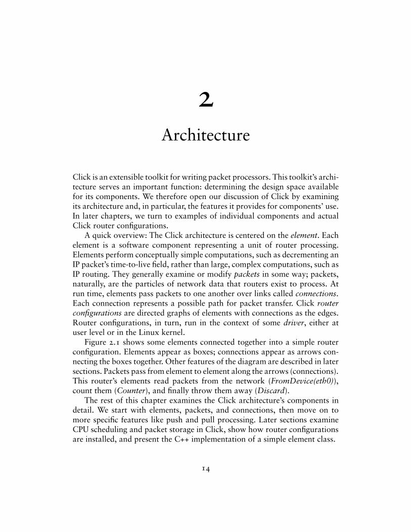
Figure 2.1 shows some elements connected together into a simple routerconfiguration. Elements appear as boxes; connections appear as arrows con-necting the boxes together. Other features of the diagram are described in latersections. Packets pass from element to element along the arrows (connections).This router’s elements read packets from the network (FromDevice(eth0)),count them (Counter), and finally throw them away (Discard).
The rest of this chapter examines the Click architecture’s components indetail. We start with elements, packets, and connections, then move on tomore specific features like push and pull processing. Later sections examineCPU scheduling and packet storage in Click, show how router configurationsare installed, and present the C++ implementation of a simple element class.
14
FromDevice(eth0) Counter Discard
elements
connections
Figure 2.1—A simple Click router configuration.
2.1 elements
The element is the most important user-visible abstraction in Click. Everyproperty of a router configuration is specified either through the choice of ele-ments or through their arrangement. Device handling, routing table lookups,queueing, counting, and so forth are all implemented by elements. Inside arunning router, each element is a C++ object that may maintain private state.
Elements have five important properties: element class, ports, configurationstrings, method interfaces, and handlers.
– Element class. An element’s class specifies that element’s data layout andbehavior. For example, the code in an element class determines how manyports elements of that class will have, what handlers they will support, andhow they will process packets. In C++, each element class corresponds toa subclass of Element.
– Ports. Each element can have any number of input and output ports. Everyconnection links an output port on one element to an input port on another.
Different ports may have different roles; for example, many elements emitnormal packets on their first output port and erroneous packets on theirsecond. The number of ports provided by an element may be fixed, or itmay depend on the element’s configuration string or how many ports wereused by the configuration. Every port that is provided must be used by atleast one connection, or the configuration is in error. Ports may be push,pull, or agnostic; these terms are defined in Section 2.4.
– Configuration string. The optional configuration string contains additionalarguments passed to the element at router initialization time. For manyelement classes, configuration strings define per-element state and fine-tuneelement behavior, much as constructor arguments do for objects.
Lexically, a configuration string is a list of arguments separated by commas.Most configuration arguments fit into one of a small set of data types: IPaddresses, for example, or integers, or lists of IP addresses.
15
Tee(2)input port output ports
element class
configuration string
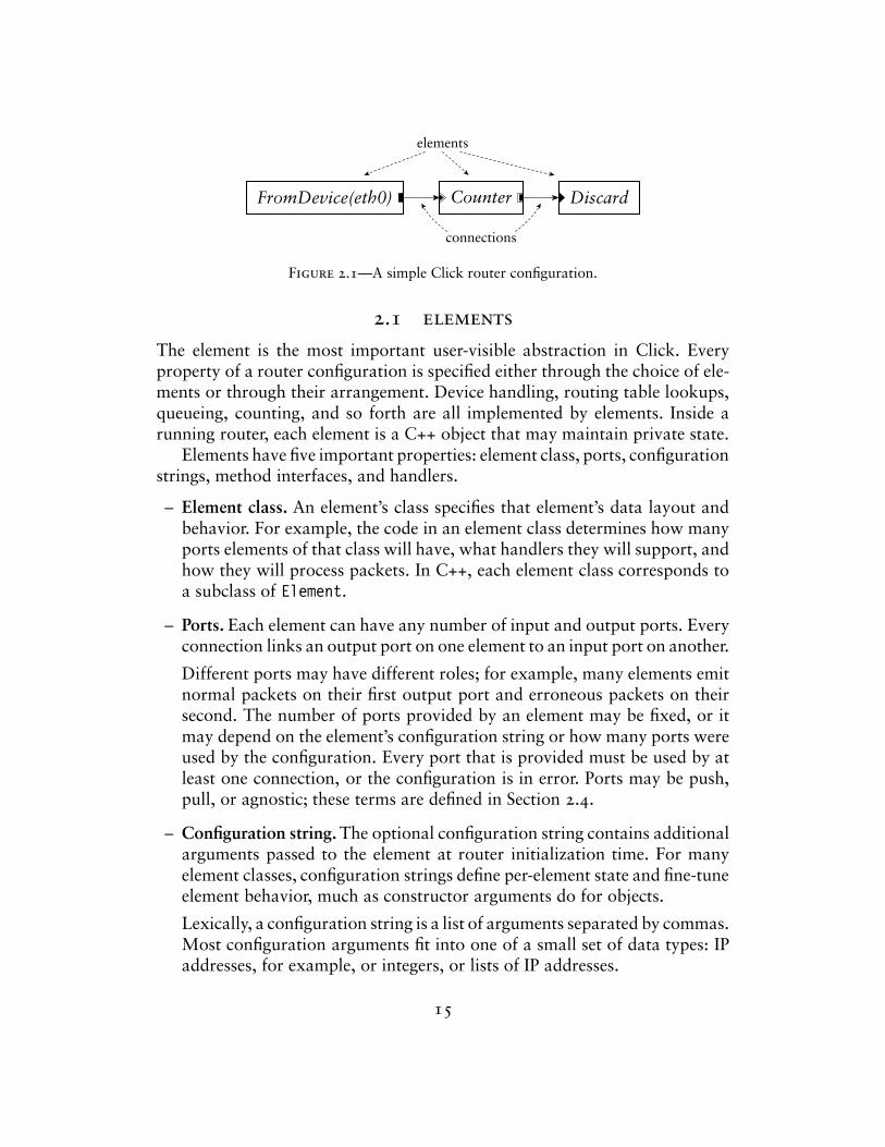
Figure 2.2—A sample element.
– Method interfaces. Each element exports methods that other elements mayaccess. This set of methods is grouped into method interfaces.
Every element supports at least the base method interface, which contains,for example, methods for transferring packets. Elements can define andimplement arbitrary other interfaces on top of this; for example, Click’sQueue element, which implements a FIFO packet queue, exports an inter-face that reports its current length.
– Handlers. Handlers are methods that are exported to the user, rather thanto other elements in the router configuration. They support simple, text-based read/write semantics, as opposed to fully general method call se-mantics. For example, the Queue element mentioned above has a handlerthat reports its current length as a decimal ASCII string, and the Counterelement in Figure 2.1 provides a handler so users can access its currentcount.
In the Linux kernel driver, handlers appear as files in the dynamic /procfile system. At user level, handlers may be accessed via a TCP/IP-basedprotocol.
Figure 2.2 shows how we diagram these properties for a sample element,Tee(2). ‘Tee’ is the element class; a Tee copies each packet received on itssingle input port, sending one copy to each output port. We draw input portsas triangles and output ports as rectangles. Configuration strings are enclosedin parentheses: the ‘2’ in ‘Tee(2)’ is interpreted by Tee as a request for twooutputs. Method interfaces and handlers are not shown explicitly; they arespecified implicitly by the element class.
The element glossary in Appendix A provides a quick description of Teeand every other element class mentioned in the text.
2.2 packets
A Click packet consists of a small packet header and the actual packet data;the packet header points to the data. This structure was borrowed from the
16
Linux kernel’s packet abstraction, sk_buff. In the Linux kernel driver, Clickpacket objects are equivalent to sk_buffs, which avoids translation or indi-rection overhead when communicating with device drivers or the kernel itself.This equivalence is hidden behind a C++ class, Packet. Other drivers reim-plement this interface; the user-level driver, for example, has a hand-writtenPacket implementation. Thus, elements may be compiled for either driverwithout change. Operations on an in-kernel Packet have zero overhead overthe corresponding Linux sk_buff operations.
Several packet headers may share the same packet data. When copyinga packet—for example, with a Tee element—Click produces a new packetheader that shares the original data. Shared packet data is copy-on-write.Elements that modify packet data first ensure that it is unshared; if it is shared,the element will make a unique copy of the data and change the packet headerto point to that copy. Packet headers are never shared, however, so headermodifications never cause a copy.
Headers contain a number of annotations in addition to a pointer to thepacket data. Annotations may be shared with Linux or specific to Click. Someannotations contain information independent of the packet data—for exam-ple, the time when the packet arrived. Other annotations cache informationabout the data. For example, the CheckIPHeader element sets the IP headerannotation on passing IP packets. This annotation marks both where the IPheader begins and where the IP payload begins, freeing later elements fromexamining the IP header’s length field. Annotations are stored in the packetheader in a fixed static order; there is currently no way to dynamically add anew kind of annotation.
Packet data is stored in a single memory buffer. This differs from theBSD-style mbuf structure, where data is stored in a linked chain of buffers.Compared to mbufs, Linux and Click’s model allows simpler, faster access inthe common case, at the cost of occasional packet copies when prepending orappending more data than will fit into a particular buffer. Such copies do notoccur in our tests.
2.3 connections
A connection passes from an output port on one element to an input porton another. Connections are the main mechanism used for linking elementstogether; each connection represents a possible path for packet transfer be-tween elements. In a running router, connections are represented as pointersto element objects, and passing a packet along a connection is implementedby a single virtual function call.
17
Connections are drawn as arrows; each arrow’s direction represents thedirection of packet flow. Each connection links a source port to a destinationport. The source port is always an output port, and the destination port isalways an input port. We also use source element and destination elementwith the obvious definitions.
Router configurations may be seen as directed graphs with elements asvertices. However, connections link ports, not elements, and each elementmay have many ports. A more complete model treats router configurations asdirected graphs with ports as vertices. Port graphs such as this have two kindsof directed edges, ordinary connections and internal edges. Internal edgesshow how packets may flow from input ports to output ports within a singleelement; an internal edge from an element’s input port i to its output port omeans that a packet that arrived on input port i might be emitted on outputport o. In the simplest model, every element has a complete graph of internaledges—that is, there are internal edges linking every input to every output.This is not always appropriate, however. For some elements, packets arrivingon a given input might be emitted on only a subset of outputs, or perhaps onnone at all. More specific internal edge information helps the system decidewhich elements are reachable from a given port; in the long run, it will alsohelp check properties of configurations. Click elements can therefore specifydetailed internal edge information if they choose.
If a path exists from an output port o to an input port i in the port graphrepresentation of a router configuration, then we say that i is downstream ofo, and, conversely, that o is upstream of i. This notion may also be generalizedto elements.
2.4 push and pull
Click supports two kinds of connections, push and pull, that implement com-plementary kinds of packet transfer. On a push connection, packets start at thesource element and are passed downstream to the destination element. On apull connection, in contrast, the destination element initiates packet transfer:it asks the source element to return a packet, or a null pointer if no packet isavailable. Many software routers provide only push connections; Clark calledpull connections upcalls [8].
These forms of packet transfer are implemented by two virtual functioncalls, push and pull. Neither kind of call is ever intended to block. For in-stance, a pull call reaching an element with no packet ready should immedi-ately return a null pointer rather than waiting for some packet to arrive. Clickis currently single-threaded, so a blocking design would simply hang.
18
FromDevice Null Null ToDevice
push(p) push(p)
returnreturn
pull()pull()return p return p
receivepacket p
enqueue pready totransmit
dequeue pand return it
send p
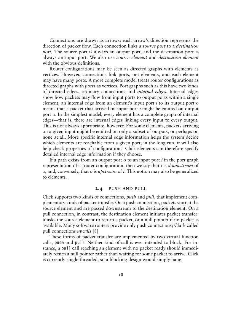
Figure 2.3—Push and pull control flow. This diagram shows functions called as a packetmoves through a simple router; time moves downwards. During the push, control flowstarts at the receiving device and moves forward through the element graph; during the pull,control flow starts at the transmitting device and moves backward. The packet p alwaysmoves forward.
The type of a connection is determined by the ports at its endpoints. Eachport in a running router is either push or pull. Connections between two pushports are push, and connections between two pull ports are pull; connectionsbetween a push port and a pull port are illegal. Elements set their ports’ typesas the router is initialized. They may also create agnostic ports, which behaveas push when connected to push ports and pull when connected to pull ports.In our configuration diagrams, black ports are push and white ports are pull;agnostic ports are shown as push or pull ports with a double outline.
Figure 2.3 shows how push and pull work in a simple router. This routerforwards packets unchanged from one network interface to another. Thecentral element in the figure is a Queue. This element enqueues packets on aFIFO queue as they are pushed to its input, and yields packets from the frontof that queue as it receives pull requests on its output. The two Null elements,which pass packets through unchanged, demonstrate agnostic ports.
Push connections are appropriate when unsolicited packets arrive at aClick router—for example, when packets arrive from a device. The routermust handle such packets as they appear, if only to queue them for later con-sideration. Pull connections are appropriate when the Click router needs tocontrol the timing of packet processing. For example, a router may transmita packet only when the transmitting device is ready. In Click, transmitting de-vices are elements with one pull input. They use pull requests to initiate packettransfer only when ready to transmit. Agnostic ports model the common casethat neither kind of processing is inherently required.
Pull connections also model the scheduling decision inherent in choosingthe next packet to send. A Click packet scheduler is simply an element withmultiple pull inputs and one pull output. It responds to a pull request by
19
FromDevice
FromDevice
ToDeviceCounter
ToDevice
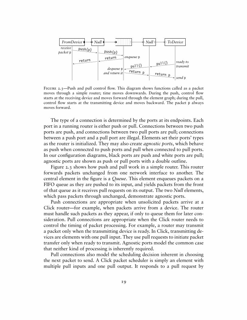
Figure 2.4—Push and pull violations. The top configuration has four errors: (1) FromDe-vice’s push output connects to ToDevice’s pull input; (2) more than one connection fromFromDevice’s push output; (3) more than one connection to ToDevice’s pull input; and (4) anagnostic element, Counter, in a mixed push/pull context. The bottom configuration, whichincludes a Queue, is legal. In a properly configured router, the port colors on either end ofeach connection will match.
choosing one of its inputs, making a pull request to that input, and returningthe packet it receives. (If it receives a null pointer, it will generally try anotherinput.) These elements make only local decisions: different scheduling behav-iors correspond to different algorithms for choosing an input. Thus, they areeasily composable. Section 4.3 discusses this further.
The following properties hold for all correctly configured routers: Pushoutputs must be connected to push inputs, and pull outputs must be connectedto pull inputs. Each agnostic port must be used as push or pull exclusively.Furthermore, if there is an internal edge linking an agnostic input port to anagnostic output port on the same element, then the ports must be either bothpush or both pull. Finally, push outputs and pull inputs must be connectedexactly once; this ensures that each packet transfer request—either pushing toan output port or pulling from an input port—uses a unique connection. Theseproperties are automatically checked by the system during router initialization.Figure 2.4 demonstrates some violations.
Configurations that violate these properties tend to be intuitively invalid.For example, the connection from FromDevice to ToDevice in Figure 2.4 isillegal because FromDevice’s output is push while ToDevice’s input is pull.But this connection is intuitively illegal, since it would mean that ToDevicemight receive packets that it was not ready to send. The Queue element, whichconverts from push to pull, also provides the temporary packet storage thisconfiguration requires.
Some further notes on agnostic ports: Agnostic ports may be connectedto other agnostic ports. At initialization time, the system will propagate con-straints until every agnostic port has been assigned to either push or pull. Tosupport agnostic ports, an element designer might write both a push functionand a pull function; only the relevant function will be called. Alternatively, the
20
designer can write a single simple_action method. This causes each packettransfer to that port to take two virtual function calls rather than one—thefirst reaches a generic push or pull, which, in turn, calls simple_action.
2.5 packet storage
Click elements do not have implicit queues on their input and output portsor the associated performance and complexity costs. Instead, queues in Clickare implemented by a separate, explicit Queue element. This gives the routerdesigner control over an important router property: how packets are stored. Italso enables valuable configurations that are difficult to arrange otherwise—for example, a single queue feeding multiple devices, or a queue feeding atraffic shaper on the way to a device. Each Queue has a push input port anda pull output port; the input port responds to pushed packets by enqueueingthem, and the output port responds to pull requests by dequeueing packetsand returning them. Queue never actively passes packets through the graph—it never calls another element’s push or pull function. Instead, and in accordwith intuition, it exclusively reacts to requests from other elements. This designwould be impossible without support for both push and pull connections: onlythe combination of push and pull allows Queue to be entirely reactive.
The user can choose a different storage policy than simple FIFO queueingsimply by using a different element. For example, Queue drops packets fromits tail when it is full. The FrontDropQueue element is mostly equivalent toQueue except that, when full, it drops packets from its head to make roomfor new packets at its tail.
2.6 cpu scheduling
Click schedules the router’s CPU with a task queue. Each router thread runsa loop that processes the task queue one element at a time. The task queue isscheduled with the flexible and lightweight stride scheduling algorithm [50].Tasks are simply elements that would like special access to CPU time. Thus,elements are Click’s unit of CPU scheduling as well as its unit of packetprocessing. An element should be on the task queue if it frequently initiatespush or pull requests without receiving a corresponding request. For example,an element that polls a device driver should be placed on the task queue;when run, it would remove packets from the driver and push them into theconfiguration. However, most elements are never placed on the task queue.They are implicitly scheduled when their push or pull methods are called.Once an element is scheduled, either explicitly or implicitly, it can initiate an
21
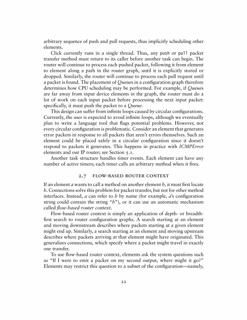
arbitrary sequence of push and pull requests, thus implicitly scheduling otherelements.
Click currently runs in a single thread. Thus, any push or pull packettransfer method must return to its caller before another task can begin. Therouter will continue to process each pushed packet, following it from elementto element along a path in the router graph, until it is explicitly stored ordropped. Similarly, the router will continue to process each pull request untila packet is found. The placement of Queues in a configuration graph thereforedetermines how CPU scheduling may be performed. For example, if Queuesare far away from input device elements in the graph, the router must do alot of work on each input packet before processing the next input packet:specifically, it must push the packet to a Queue.
This design can suffer from infinite loops caused by circular configurations.Currently, the user is expected to avoid infinite loops, although we eventuallyplan to write a language tool that flags potential problems. However, notevery circular configuration is problematic. Consider an element that generateserror packets in response to all packets that aren’t errors themselves. Such anelement could be placed safely in a circular configuration since it doesn’trespond to packets it generates. This happens in practice with ICMPErrorelements and our IP router; see Section 5.1.
Another task structure handles timer events. Each element can have anynumber of active timers; each timer calls an arbitrary method when it fires.
2.7 flow-based router context
If an element a wants to call a method on another element b, it must first locateb. Connections solve this problem for packet transfer, but not for other methodinterfaces. Instead, a can refer to b by name (for example, a’s configurationstring could contain the string “b”), or it can use an automatic mechanismcalled flow-based router context.
Flow-based router context is simply an application of depth- or breadth-first search to router configuration graphs. A search starting at an elementand moving downstream describes where packets starting at a given elementmight end up. Similarly, a search starting at an element and moving upstreamdescribes where packets arriving at that element might have originated. Thisgeneralizes connections, which specify where a packet might travel in exactlyone transfer.
To use flow-based router context, elements ask the system questions suchas “If I were to emit a packet on my second output, where might it go?”Elements may restrict this question to a subset of the configuration—namely,
22
RED Classifier Discard
· · ·
Strip
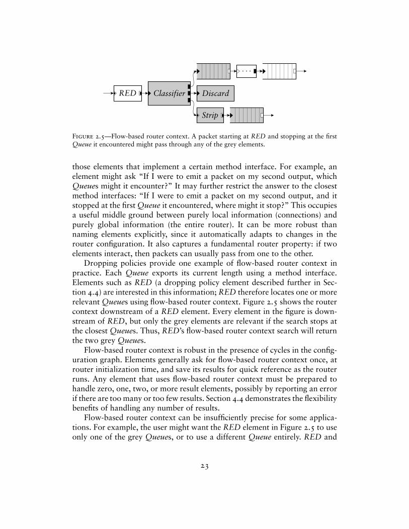
Figure 2.5—Flow-based router context. A packet starting at RED and stopping at the firstQueue it encountered might pass through any of the grey elements.
those elements that implement a certain method interface. For example, anelement might ask “If I were to emit a packet on my second output, whichQueues might it encounter?” It may further restrict the answer to the closestmethod interfaces: “If I were to emit a packet on my second output, and itstopped at the first Queue it encountered, where might it stop?” This occupiesa useful middle ground between purely local information (connections) andpurely global information (the entire router). It can be more robust thannaming elements explicitly, since it automatically adapts to changes in therouter configuration. It also captures a fundamental router property: if twoelements interact, then packets can usually pass from one to the other.
Dropping policies provide one example of flow-based router context inpractice. Each Queue exports its current length using a method interface.Elements such as RED (a dropping policy element described further in Sec-tion 4.4) are interested in this information; RED therefore locates one or morerelevant Queues using flow-based router context. Figure 2.5 shows the routercontext downstream of a RED element. Every element in the figure is down-stream of RED, but only the grey elements are relevant if the search stops atthe closest Queues. Thus, RED’s flow-based router context search will returnthe two grey Queues.
Flow-based router context is robust in the presence of cycles in the config-uration graph. Elements generally ask for flow-based router context once, atrouter initialization time, and save its results for quick reference as the routerruns. Any element that uses flow-based router context must be prepared tohandle zero, one, two, or more result elements, possibly by reporting an errorif there are too many or too few results. Section 4.4 demonstrates the flexibilitybenefits of handling any number of results.
Flow-based router context can be insufficiently precise for some applica-tions. For example, the user might want the RED element in Figure 2.5 to useonly one of the grey Queues, or to use a different Queue entirely. RED and
23
other elements therefore let the user override flow-based router context withan explicit list of element names.
Click currently uses flow-based router context mostly to check assertions—that a needed element is somewhere downstream, for example. When usedthis way, there is no risk of finding the wrong elements, and flow-based routercontext simply improves the system’s ability to detect configuration errors.
2.8 installing configurations
Click configurations run inside a driver, which implements facilities used byall elements. There are currently two drivers: the user-level driver runs as anapplication at user level, and the Linux kernel driver runs as a downloadablemodule in the Linux kernel. The user-level driver is useful for debugging andrunning repeatable tests; it can even receive packets from the network, usingOS mechanisms originally designed for packet sniffers. However, it cannotprevent the operating system’s networking stack from handling a packet. Thekernel driver can completely replace the OS networking stack, changing aconventional PC into an arbitrary router. This driver can also achieve highperformance for PC hardware; see Chapters 7 and 8.
The user installs a Click configuration by writing its definition in a simpletextual language and passing that definition to the appropriate driver. (Chap-ter 3 describes this language in detail.) The driver then parses the definition,checks it for errors, initializes every element, and puts the router on line.It breaks the initialization process into stages. In the early stages, elementsset object variables, add and remove ports, and specify whether those portsare push or pull. In later stages, they query flow-based router context, placethemselves on the task queue, and, in the kernel driver, attach to Linux kernelstructures. This staged design supports cyclic configurations better than anyfixed initialization order, which might fall prey to circular dependencies.
To run a configuration in the user-level driver, the user simply runs a clickapplication, passing a configuration file’s pathname on the command line.Arbitrary numbers of user-level drivers can be active simultaneously.
The Linux kernel driver’s installation policy is slightly more complex due toits location in the kernel. This kernel driver runs one router configuration at atime. To install a configuration, the user writes a Click-language description tothe special file /proc/click/config. Installing a new configuration normallydestroys any old configuration; for instance, any packets stored in old queuesare dropped. This starts the new configuration from a predictable emptystate. However, Click supports several techniques for changing a configurationwithout losing information:
24
– Handlers. Some elements allow the user to reconfigure them with handlersas the router is running. Handler modifications are generally local to anelement. For example, the Queue element has a handler that changes itsmaximum length, and a Click routing table element would likely provideadd_route and del_route handlers as access points for user-level routingprotocol implementations.
– Hot swapping. Some configuration changes, such as adding new elements,are more complex than handlers can support. In these cases, the user canwrite a new configuration file and install it with a hot-swapping option.This will only install the new configuration if it initializes correctly—ifthere are any errors, the old configuration will continue routing packetswithout a break. Also, if the new configuration is correct, it will atomicallytake the old configuration’s state before being placed on line; for example,any enqueued packets are moved into the new configuration. This happensonly with element classes that explicitly support it, and only when the newelements have the same names as the old ones.
– New element classes. Element class definitions can be added to and re-moved from a running Click kernel driver. A Click configuration can re-quire a particular set of elements with a require statement; when thatconfiguration is installed, the driver will automatically load an object filecontaining those elements. This feature could be used to support active net-working, where packets can refer to specialized per-packet routing code. InClick, that code could consist of elements that are added to the driver dy-namically; a new configuration using those elements could be hot-swappedin.
2.9 element implementation
Each Click element class corresponds to a subclass of the C++ class Element,which has about 20 virtual functions. Element provides reasonable defaultimplementations for many of these, so most subclasses must override six ofthem or less. Only three virtual functions are used during router operation,namely push, pull, and run_scheduled (used by the task scheduler); the othersare used for identification, push and pull specification, configuration, initial-ization, handlers, and so forth.
Subclasses of Element are easy to write, so we expect that users will easilywrite new element classes as needed. In fact, the complete implementation ofa simple working element class takes less than 10 lines of code; see Figure 2.6.
25
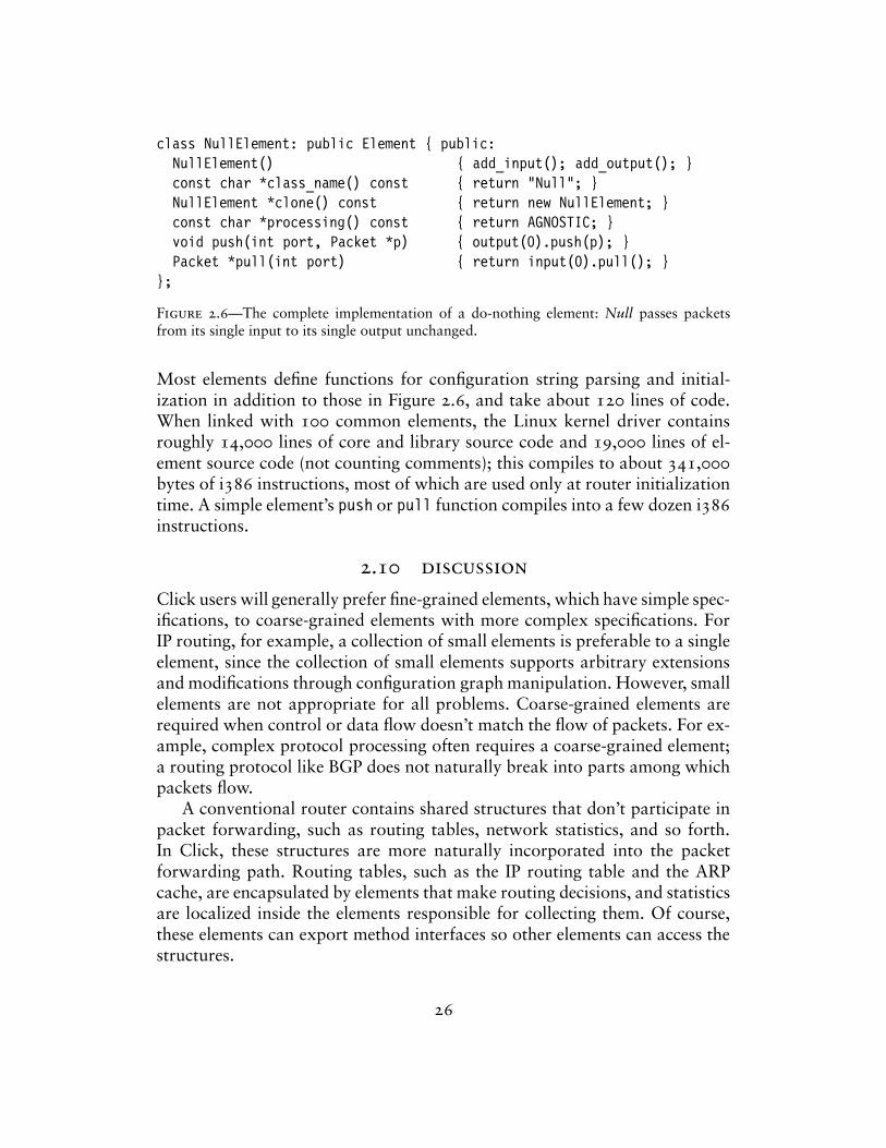
class NullElement: public Element { public:NullElement() { add_input(); add_output(); }const char *class_name() const { return "Null"; }NullElement *clone() const { return new NullElement; }const char *processing() const { return AGNOSTIC; }void push(int port, Packet *p) { output(0).push(p); }Packet *pull(int port) { return input(0).pull(); }
};
Figure 2.6—The complete implementation of a do-nothing element: Null passes packetsfrom its single input to its single output unchanged.
Most elements define functions for configuration string parsing and initial-ization in addition to those in Figure 2.6, and take about 120 lines of code.When linked with 100 common elements, the Linux kernel driver containsroughly 14,000 lines of core and library source code and 19,000 lines of el-ement source code (not counting comments); this compiles to about 341,000bytes of i386 instructions, most of which are used only at router initializationtime. A simple element’s push or pull function compiles into a few dozen i386instructions.
2.10 discussion
Click users will generally prefer fine-grained elements, which have simple spec-ifications, to coarse-grained elements with more complex specifications. ForIP routing, for example, a collection of small elements is preferable to a singleelement, since the collection of small elements supports arbitrary extensionsand modifications through configuration graph manipulation. However, smallelements are not appropriate for all problems. Coarse-grained elements arerequired when control or data flow doesn’t match the flow of packets. For ex-ample, complex protocol processing often requires a coarse-grained element;a routing protocol like BGP does not naturally break into parts among whichpackets flow.
A conventional router contains shared structures that don’t participate inpacket forwarding, such as routing tables, network statistics, and so forth.In Click, these structures are more naturally incorporated into the packetforwarding path. Routing tables, such as the IP routing table and the ARPcache, are encapsulated by elements that make routing decisions, and statisticsare localized inside the elements responsible for collecting them. Of course,these elements can export method interfaces so other elements can access thestructures.
26
Several other modular networking systems are built around an abstractionthat represents individual network flows—TCP sessions and the like [22, 30].These systems automatically create and destroy modules as network flows areencountered. This is a fast, limited form of configuration installation, as eachnew or deleted flow changes a localized section of the configuration. Hot-swapinstallation is fast in Click—on a 700 MHz Pentium III, installing a 50-elementconfiguration takes less than a tenth of a second—but not fast enough tosupport flow creation and deletion. Most of the benefits of a flow-based designcan be realized in Click as is; many configurations only require per-flow-classstate and CPU scheduling, and elements can cooperate to maintain per-flowprivate state. Unlike flow-based systems, however, Click cannot schedule theCPU per individual flow.
27
3Language
The Click programming language textually describes Click router configura-tions. Two of its constructs are sufficient to describe any configuration graph:declarations create elements and connections connect elements together. How-ever, a language with only these constructs would scale poorly to large config-urations. Click’s language contains additional structure to aid users: syntacticsugar improves readability, and compound elements, described in Section 3.4,provide an abstraction mechanism for configuration fragments.
Two goals guided the language’s design, readability and convenience fortools. The importance of readability is clear enough; a modular networkingsystem is only extensible as far as its configurations may be easily read andmodified. The second goal, convenience for tools, means that it should be easyto design, use, and compose automatic tools that analyze and manipulate Clicklanguage files. Tools like this can optimize or transform Click configurationsor ensure that application-level properties hold; see Chapter 6. We prefer abroad, open-ended set of tools to one tool, no matter how powerful thattool. For example, the Ensemble system for composing network protocolstacks [25] is built around a single tool, a theorem prover. It can performchecks and optimizations, but only with extensive human intervention. InClick, we chose to sacrifice the kind of correctness guarantees achievable withtheorem proving for ease of use and ease of tool design.
These goals led us to a set of more concrete design principles.
– The language is declarative: it simply describes the configuration graph.Contrast this with scripting as embodied by Tcl, where directives for ma-nipulating a system are added to a general-purpose programming language.The Berkeley ns network simulator [34] uses Tcl as a base; ns configura-tions are embedded in, and inseparable from, imperative Tcl scripts thatmay perform other arbitrary actions. Declarative languages have readabil-ity advantages, and declarative programs can be analyzed and manipulated
28

more easily than imperative programs.
– The language is simple. We have kept new constructs to a minimum, prefer-ring to implement language extensions through special-purpose elements.This choice limits the mechanisms that users must learn and tools mustimplement while achieving great flexibility.
– Click-language programs and configuration graphs are equivalent. Anyconfiguration corresponds to a simple program in the Click language, andit is easy to translate back and forth between programs and graphs.
– Tools should not need to fully understand Click’s semantics—for example,they should not have to understand what every element does. Therefore,the language supports blind manipulation: tools that do not understandelement semantics can transform configuration programs while preservingcorrectness.
The rest of this chapter describes the language we have designed based onthese principles: its syntax, its abstraction mechanisms, and its limitations.
3.1 syntax
Again, a configuration graph consists of elements connected together. Eachelement has an element class, which is specified by name, and optionally aconfiguration string. Elements are connected through their input and outputports. In the Click language, input and output ports are distinguished bynumber and elements are distinguished by name. Each element in the config-uration has a unique name that the user can optionally specify. These namesdistinguish elements during the parsing process, and also let the user, or otherprograms, access particular elements once the configuration is running.
The language’s fundamental constructs, declarations and connections, havethe following syntax:
name :: class(config-string); // declarationname1 [port1] -> [port2] name2; // connection
(All semicolons are optional.) The connection statement “name1 [port1] ->[port2] name2” creates a connection from name1’s output port port1 toname2’s input port port2. Elements must be declared before they are used inconnections. Any configuration can be described with these two statements,but additional syntactic sugar makes configurations more pleasant to writeand to read:
29
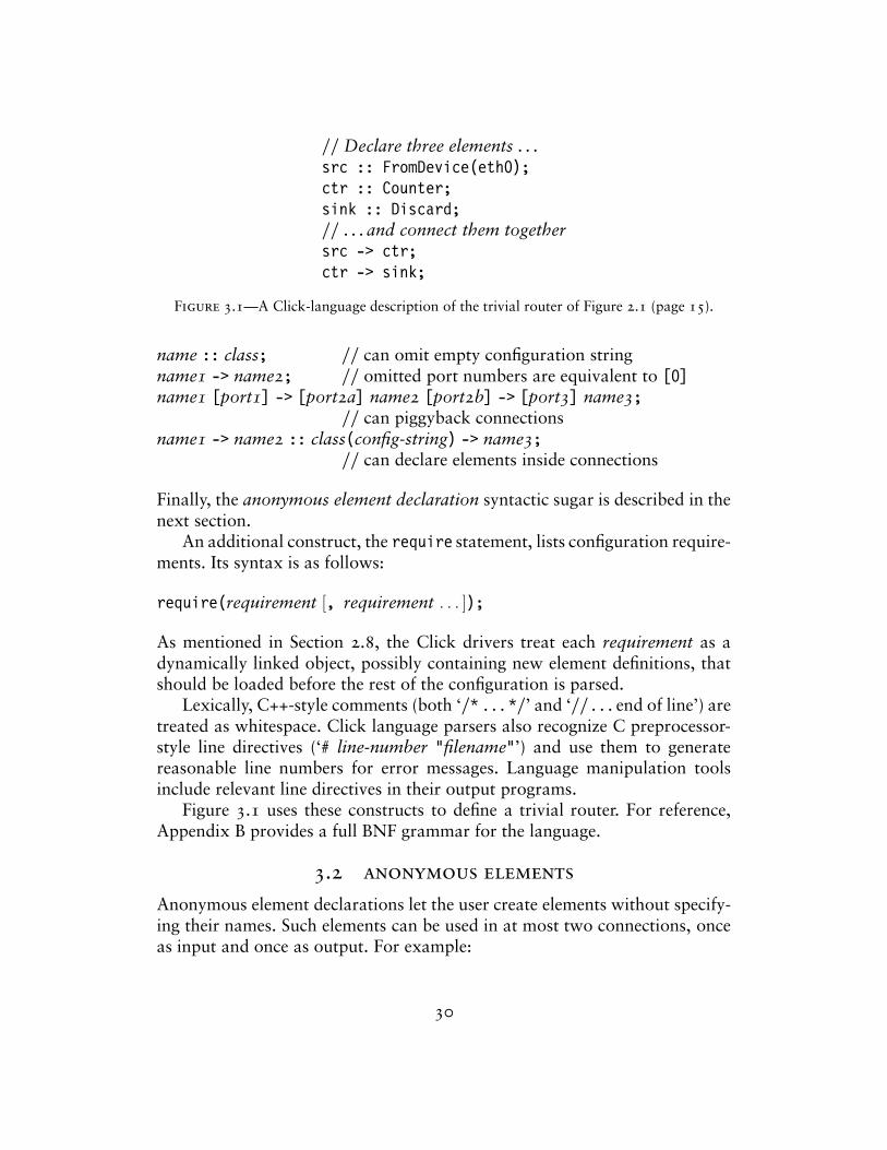
// Declare three elements . . .src :: FromDevice(eth0);ctr :: Counter;sink :: Discard;// . . . and connect them togethersrc -> ctr;ctr -> sink;
Figure 3.1—A Click-language description of the trivial router of Figure 2.1 (page 15).
name :: class; // can omit empty configuration stringname1 -> name2; // omitted port numbers are equivalent to [0]name1 [port1] -> [port2a] name2 [port2b] -> [port3] name3;
// can piggyback connectionsname1 -> name2 :: class(config-string) -> name3;
// can declare elements inside connections
Finally, the anonymous element declaration syntactic sugar is described in thenext section.
An additional construct, the require statement, lists configuration require-ments. Its syntax is as follows:
require(requirement [, requirement . . . ]);
As mentioned in Section 2.8, the Click drivers treat each requirement as adynamically linked object, possibly containing new element definitions, thatshould be loaded before the rest of the configuration is parsed.
Lexically, C++-style comments (both ‘/* . . . */’ and ‘// . . . end of line’) aretreated as whitespace. Click language parsers also recognize C preprocessor-style line directives (‘# line-number "filename"’) and use them to generatereasonable line numbers for error messages. Language manipulation toolsinclude relevant line directives in their output programs.
Figure 3.1 uses these constructs to define a trivial router. For reference,Appendix B provides a full BNF grammar for the language.
3.2 anonymous elements
Anonymous element declarations let the user create elements without specify-ing their names. Such elements can be used in at most two connections, onceas input and once as output. For example:
30
FromDevice(eth0) -> Counter -> Discard;
Figure 3.2—Another Click-language description of the trivial router of Figure 2.1.
name1 -> class(config-string) -> name2; // one input, one outputname -> class(config-string); // input onlyclass(config-string) -> name; // output onlyclass(config-string); // no inputs or outputs
As usual, empty configuration strings may be omitted. The system constructs aname for each anonymous element; these names have the form ‘class@i’, wherei is an integer chosen to ensure uniqueness. Anonymous element declarationsimprove readability by avoiding clutter. A language without anonymous decla-rations could be compared, albeit with some exaggeration, to a programminglanguage in which each subexpression had to be uniquely named. TypicalClick configurations use anonymous declarations for half their elements. TheClick-language description in Figure 3.2 is equivalent to Figure 3.1, but usesanonymous elements.
Besides making configurations more readable, anonymous elements pro-vide an excellent means for implementing language extensions. For example,how might the user set the scheduling priority for an element, or define anabbreviation for a common network address? The obvious solution wouldinvolve extended syntax:
address eth0_addr = 00:e0:98:09:ab:af;arpq :: ARPQuerier(18.26.4.44, eth0_addr);arpq -> td :: ToDevice(eth0) priority 10;
However, this adds unnecessary complexity to the language and does notgeneralize well. Instead, Click implements extensions through special infor-mation elements—ordinary elements whose configuration strings define someextension property. For example:
AddressInfo(eth0_addr 00:e0:98:09:ab:af);arpq :: ARPQuerier(18.26.4.44, eth0_addr);arpq -> td :: ToDevice(eth0);ScheduleInfo(td 10);
The AddressInfo and ScheduleInfo statements are simply anonymous ele-ment declarations. Information elements are described further in Section 4.7.
The generated names of anonymous elements are valid identifiers in thelanguage. Thus, a tool can parse a program that uses anonymous elements and
31
generate an equivalent program in which all elements are named explicitly.Users are discouraged from using the distinguishing ‘@’ character in theirelement names for stylistic reasons, but nothing prevents them from doing so.This property helps achieve equivalence between programs and graphs.
Correct programs containing anonymous elements can be parsed with-out knowing the available set of element classes. This helps support blindmanipulation. The rule is simple—every identifier not previously declared isan element class. Parsing a program using this rule preserves correctness: aprogram generated from the parsed configuration graph will be correct ifand only if the original program was correct. Thus, although tools using thisrule will silently accept some kinds of errors, they will not change erroneousconfigurations into valid ones or vice versa.
3.3 configuration strings
Configuration strings in Click are comma-separated lists of arguments delim-ited by parentheses. Each individual argument is essentially a string that ispassed to the element for parsing. Before parsing, however, the Click driverreplaces any comments with single space characters and removes any lead-ing and trailing space from each argument. Arguments can contain single- ordouble-quoted strings; these are useful if an argument contains unbalancedparentheses, leading or trailing space, or characters that might be mistakenfor comments.
Strictly speaking, what elements do with the arguments is not part ofthe Click language. Elements are free to parse argument strings in whateverway they choose. Practically speaking, however, the configuration string “lan-guage” is important for users, who must learn it just as they learn the languagefor connecting elements together.
Most elements we have designed so far use a common library for pars-ing their configuration arguments. This library parses arguments with thefollowing characteristics:
– A configuration argument is either a single item or a list of items. Items ina list are separated by spaces.
– An individual item can be a string (‘"this is"a_string’), word (‘a_word’),Boolean value (‘true’, ‘false’), integer (‘90’, ‘-999’, ‘0x8F’), real number(‘0.5’; the data will be returned in fixed-point decimal or binary represen-tation), IP address (‘18.26.4.44’), IP network address (‘18.26.4.0/24’),Ethernet address (‘00:02:B3:06:36:EE’), element name (‘elt’), or IPv6 ad-
32
dress (‘1080::8:800:200C:417A’, ‘::’, ‘::18.26.4.15’). New types can beplugged into the library dynamically.
– The simplest means of accessing the library takes an entire set of argumentsand produces the corresponding data or an error. This interface supportspositional arguments, some of which may be optional, as well as keywordarguments like ‘APPEND true’. Elements may also use a lower-level inter-face that merely parses items; in this case, the elements are themselvesresponsible for separating arguments into items and for reporting errors.
This design emphasizes flexibility at the expense of commonality betweenelements. Clearly, elements can support natural representations for data typesnot mentioned above, since the elements themselves determine how stringsare parsed into data. Several of our elements take advantage of this flexibility,such as the Classifier elements described in Section 4.2. However, this sameproperty makes it difficult to write a complete typechecker for configurationstrings without relying on element source code.
3.4 compound elements
Compound element classes let users define their own element classes with-out writing C++ code. They are the Click language’s abstraction mechanism,providing flexible macros for router configuration graphs. Operationally, com-pound element classes are router configuration fragments that are treated likeelement classes. They are most commonly created by an elementclass state-ment, which has the following syntax:
elementclass Name {. . . Click statements . . .
}
After this statement, Name is an element class that corresponds to the Clickconfiguration fragment inside the braces. Declaring an “element” of className adds a duplicate of that fragment to the configuration. We call the “ele-ment” a compound element; each actual element in the fragment it representsis called a component of the compound. For example, this compound elementclass has three components (an InfiniteSource element, a Counter element,and a Discard element):
elementclass Example {s :: InfiniteSource; c :: Counter; d :: Discard;s -> c -> d;
}
33
Only components remain in the final configuration graph—all compoundelement structure is compiled away. This process, called flattening, ensures thata compound element has no more overhead than the corresponding collectionof components. It also lets tools manipulate flat configuration graphs, asopposed to hierarchical graphs containing compound element classes. Duringthe flattening process, compound element components are given names thatreflect their origin. A component named ‘e’ of a compound element named‘compound’ is named ‘compound/e’ in the flattened configuration. For example,this configuration, with a compound element,
elementclass Example {s :: InfiniteSource; c :: Counter; d :: Discard;s -> c -> d;
}e :: Example;
flattens into this configuration:
e/s :: InfiniteSource; e/c :: Counter; e/d :: Discard;e/s -> e/c -> e/d;
Generated names like ‘e/s’ are valid identifiers in the language. As with anony-mous element names, this helps achieve equivalence between programs andconfiguration graphs: a flattened configuration graph may be directly trans-lated into an equivalent valid program.
The elementclass statement can redefine existing element classes. Forexample, this statement redefines the Queue class:
elementclass Queue {. . . new definition . . .
}
Inside the new definition, any use of ‘Queue’ would refer to the original Queueclass. It is not possible to define recursive or mutually recursive element classes.
Another elementclass variant defines an alias for an existing elementclass. For example, after this statement,
elementclass MyQueue Queue;
the identifier ‘MyQueue’ is a synonym for Queue—specifically, for the Queueclass that was active when the synonym statement was parsed.
The language supports nested compound element definitions. For example:
34
elementclass Example2 {elementclass NestedExample {
. . . Click statements . . .}n :: NestedExample;
}
The scope of the nested compound element class is limited to the element classin which it appears.
Ports
Like any element, compound elements may have input and output ports.Each connection to or from a compound element port is transformed byflattening into a connection to or from one of its components’ ports. Insidea compound element class, the special pseudoelements input and outputspecify how this transformation proceeds. Consider a compound element e.If e/input’s output port i has a connection to a component e/c, then everyconnection to a e’s input port i will flatten into a connection to its componente/c. The output pseudoelement plays a corresponding role for output ports.Compound element components are isolated from the main configurationexcept through input and output.
For example, in the following configuration, the Example3 compoundelement has one input and zero outputs:
elementclass Example3 {input[0] -> Counter -> Discard;
}FromDevice(eth0) -> Example3;
The connection between FromDevice and Example3’s input port transformsinto a connection to the Counter component. Therefore, the above configura-tion flattens to something like this:
FromDevice(eth0) -> Counter -> Discard;
Figure 3.3 shows a compound element class with one input and one outputas written in the language and as it might be drawn.
Particular input or output ports may be connected multiple times. This willexpand each connection to that port into multiple connections to components.For example, this use of Example4,
35
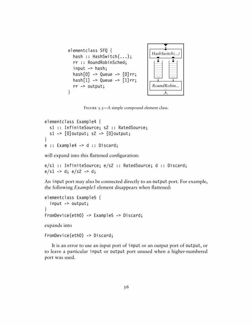
elementclass SFQ {hash :: HashSwitch(...);rr :: RoundRobinSched;input -> hash;hash[0] -> Queue -> [0]rr;hash[1] -> Queue -> [1]rr;rr -> output;
}
HashSwitch(...)
RoundRobin...
Figure 3.3—A simple compound element class.
elementclass Example4 {s1 :: InfiniteSource; s2 :: RatedSource;s1 -> [0]output; s2 -> [0]output;
}e :: Example4 -> d :: Discard;
will expand into this flattened configuration:
e/s1 :: InfiniteSource; e/s2 :: RatedSource; d :: Discard;e/s1 -> d; e/s2 -> d;
An input port may also be connected directly to an output port. For example,the following Example5 element disappears when flattened:
elementclass Example5 {input -> output;
}FromDevice(eth0) -> Example5 -> Discard;
expands into
FromDevice(eth0) -> Discard;
It is an error to use an input port of input or an output port of output, orto leave a particular input or output port unused when a higher-numberedport was used.
36
Anonymous compound element classes
Compound element classes may also be anonymous. To create an anonymouscompound element class, the user simply writes a configuration fragment inbraces where an element class was expected—for example, after ‘::’ in anelement declaration:
sfq :: {hash :: HashSwitch(...); rr :: RoundRobinSched;input -> hash;hash[0] -> Queue -> [0]rr; hash[1] -> Queue -> [1]rr;rr -> output;
}
or, even more anonymously,
FromDevice(eth0) -> { input -> Counter -> output } -> Discard;
Anonymous compound elements are useful for debugging as well as con-figuration structuring. Consider the following program:
q :: Queue;// . . .Source1 -> ... -> q;Source2 -> ... -> q;q -> ... -> Sink;
Say we would like to print each packet as it enters the Queue. Withoutcompound elements, one would have to change at least one of the uses of q;for example:
qp :: Print(q) -> q :: Queue;// . . .Source1 -> ... -> qp;Source2 -> ... -> qp;q -> ... -> Sink;
With a compound element, only q’s declaration must be changed:
q :: { input -> Print(q) -> Queue -> output };// . . .Source1 -> ... -> q;Source2 -> ... -> q;q -> ... -> Sink;
37
3.5 compound element arguments and overloading
Compound element classes, like ordinary element classes, take configurationarguments and can have varying numbers of arguments, input ports, and out-put ports. Formal parameters define the arguments that a compound elementclass should take; overloading lets several compound element definitions withdifferent numbers of arguments or ports share a single name.
A formal parameter is a sequence of alphanumeric characters precededby a dollar sign, such as $a or $10_4_buddy. A compound element class mayoptionally begin with a list of parameters. For example, the following elementtakes exactly two arguments:
elementclass Example6 {$arg1, $arg2 | input -> Discard;
}e :: Example6(a, b); // OKe2 :: Example6; // error—wrong number of arguments
Formal parameters are used inside the configuration strings of component ele-ments. When a compound element is declared, occurrences of formal parame-ters in its components’ configuration strings are replaced by the correspondingconfiguration arguments. For example:
elementclass GatewayDevice {$device | from :: FromDevice($device) -> output;
}g :: GatewayDevice(eth0) -> Discard;
expands to
g/from :: FromDevice(eth0) -> Discard;
When compound elements are nested, formal parameters are lexically scoped.Formal parameters let a compound element class support a fixed number
of positional arguments. The overloading mechanism extends this to supportoptional arguments, as well as different behavior based on numbers of inputor output ports. Every compound element class can correspond to a number ofdefinitions, which are textually separated by ‘||’. These definitions are distin-guished by their numbers of formal parameters, input ports, and output ports.For each declared compound element, the system checks how many argumentswere supplied and how many inputs and outputs were actually used. Then itsearches for a matching definition. If one is found, then it is expanded; if noneis found, it is an error. For example, the following ShapedQueue element classsupports an optional capacity argument, just like Queue itself:
38
elementclass ShapedQueue {input -> Queue -> Shaper(10000) -> output;||$cap | input -> Queue($cap) -> Shaper(10000) -> output;
}q1 :: ShapedQueue; // OK; uses first definitionq2 :: ShapedQueue(1024); // OK; uses second definitionq3 :: ShapedQueue(1024, 10000); // error—no matching definition
The following VerboseCheckIPHeader element class has an optional secondoutput port, just like CheckIPHeader itself:
elementclass VerboseCheckIPHeader {input -> c :: CheckIPHeader -> output;c[1] -> Print(CheckIPHeader) -> Discard;||input -> c :: CheckIPHeader -> output;c[1] -> Print(CheckIPHeader) -> [1]output;
}
A variant of overloading lets the user add new definitions to an existingelement class. For example, this definition adds a two-argument version ofQueue:
elementclass Queue {... || // ‘dot dot dot’ is part of the syntax$capacity, $rate | input -> Queue($capacity)
-> Shaper($rate) -> output;}q1 :: Queue; // built-in Queueq2 :: Queue(1024); // built-in Queueq3 :: Queue(1024, 10000); // overloaded Queue definition above
It is an error for a single compound element class to contain two overloadeddefinitions with the same signature (that is, the same numbers of argumentsand input and output ports). A compound element class that overloads anexisting element class (‘elementclass Name { ... || definitions }’) mayoverride a former definition with the same signature, however.
When choosing the definition that corresponds to a given compound el-ement declaration, Click only considers the definitions that were lexicallyvisible at the point of declaration. For example:
39
elementclass Example7 {Idle;
}e1 :: Example7(test); // error—no matching definition visible hereelementclass Example7 {
... || $arg | Idle;}e2 :: Example7(test); // now it’s OK
Thus, it is still impossible to write recursive or mutually recursive elementclass definitions in Click.
Compound element configuration arguments are only meaningful insidethe configuration strings of components. They cannot, for example, changethe element class of a given component, or cause components to be added toor subtracted from the compound. Overloading helps somewhat, but is basedonly on the number of configuration arguments, not on their values. However,it is possible to build a compound element that sends packets through differentsets of components based on the value of its configuration string.
The keys are the StaticSwitch and StaticPullSwitch elements. StaticSwitchhas one push input and several push outputs. Its configuration string con-tains an output port number; all packets arriving on its input are emittedon that output port. StaticPullSwitch is the pull equivalent: its configurationstring contains an input port number, and all pull requests are forwarded tothat input port. The following compound element uses StaticSwitch to imple-ment a selective checksum check. (The CheckIPHeader element checks an IPheader’s length and checksum for sanity; CheckIPHeader2 does the work ofCheckIPHeader except for the checksum check.)
elementclass MaybeChecksum { $checksum_p |input -> sw :: StaticSwitch($checksum_p);sw[0] -> CheckIPHeader2 -> output;sw[1] -> CheckIPHeader -> output;
};c1 :: MaybeChecksum(0); // uses CheckIPHeader2, skips checksumc2 :: MaybeChecksum(1); // uses CheckIPHeader, checks checksum
The click-undead dead code elimination tool can remove StaticSwitch and anyunused elements from the resulting configuration; see Section 6.4.
40
3.6 discussion and limitations
The Click programming language has achieved its goals. The language isreadable and easy to work with. Compound elements let users create librariesof useful configuration fragments; they are also convenient when debuggingconfigurations. As Chapter 6 will show, our design principles have created aconvenient language for automatic processing. Also, Click’s division of laborbetween element classes and the language works well in practice. Elementclasses determine how packets move locally and perform all complex cal-culations; the language is exclusively concerned with abstraction and howelements are combined. This division of labor has kept both language andsystem simple, focused, and useful.
The language is not necessarily complete, however. Possible areas for fur-ther work include adding features to compound elements and adding moreinformation about individual element types.
Compound element classes support many of the features of native C++element classes, but not all. For example, native classes can support keywordarguments, perform complex calculations based on their arguments, and cre-ate handlers that users may access; compound elements can do none of thesethings. Also, since compound elements are compiled away at router initializa-tion time, their internal structure is visible in the created router. Compoundelements are an imperfect abstraction mechanism: they do not hide themselvesfrom the user, and they are strictly less powerful than native element classes.We plan to add some features missing from compound elements, particularlyhandlers, to a future release of Click. Currently, users who want these featuresmust write their element classes in C++.
The decision to leave configuration string parsing up to individual ele-ments has problematic consequences even beyond the difficulty of writing atype checker. For example, it is dangerous for any automatic tool to changethe name of any element in a Click program: some other element might refer tothat name inside its configuration string, but without knowing which config-uration arguments are element names, it is impossible to patch any referencesthat do exist. We initially chose the current design for its simplicity and be-cause it supports blind manipulation. It was a good choice for building up thesystem. Now, however, as elements are more plentiful and as configurationsgrow bigger, checking configurations off line for errors may become moreimportant than simplicity. In future, every element class may be accompaniedby one or more specifications, such as descriptions of the types of its con-figuration arguments, its numbers of input and output ports and how thosenumbers are determined, and whether it modifies passing packets. Providing
41

this kind of semantic information to Click language tools would make it easierto check configurations for correctness off line, and would not burden elementcreators unnecessarily.
42
4Elements
This chapter describes a cross-section of existing elements and discusses thedesign principles on which these elements were built; Chapter 5 presents aselection of router configurations that use the elements shown here. Click’savailable elements, and the ease of combining elements into configurations,goes to the heart of Click’s utility. Section 4.1 begins with a description ofour element design priciples, some of which are properties inherent in theClick architecture. The rest of the chapter describes particular elements, fo-cusing on how these elements support composition. The packet scheduling,dropping policy, and TCP/IP rewriting elements, in particular, demonstratehow the Click element abstraction creates powerful and flexible networkingcomponents.
4.1 overview
Every element class must address the simple set of primitives on which el-ements are built: configuration strings and input and output ports that canbe push or pull. The characteristics of these primitives create a simple designmethodology. For example, an element that divides packets into categories,such as a routing table, will have push ports, generally one output port percategory. (In an element with all pull ports, each packet’s output port has beendetermined before the packet itself is seen, so categorization based on packetcontents is impossible unless the element has internal packet storage.) Click’selements follow this methodology as well as some rules we imposed ourselves:
– Separate functionality within reason. Each element should have a simplespecification. For example, elements that classify packets should be sepa-rated from elements that modify them. However, separations that wouldresult in complex inter-element communication should be avoided, par-ticularly if the elements would not exchange packets or if they would bedifficult to understand individually.
43
This rule argues for small elements and, therefore, large router configu-rations. Complex router behavior is implemented by combining simpleparts.
– Whenever possible, use different ports rather than packet data to distin-guish between different kinds of packets. For example, the ARPQuerierelement takes both IP packets and ARP responses. It could examine flagsin the packet header to distinguish between these packet classes, but in-stead, it has two input ports—one for IP, one for ARP. This makes theconfiguration easier to read, since different kinds of packets take distinctpaths. It marginally speeds up the configuration by eliminating redundantpacket header comparisons. It also tends to localize packet classificationin explicit classification elements, which, in turn, facilitates optimization.
When these rules are followed consistently, elements naturally fall intocategories distinguished by their input and output port characteristics.
– Packet sources spontaneously generate packets, either by reading themfrom the network (FromDevice), reading them from a dump file (From-Dump), creating them from specified data (InfiniteSource, RatedSource),or creating them from random data (RandomSource). They have one out-put and no inputs.
– Packet sinks remove packets from the system, either by dropping them(Discard, TimedSink), sending them to the network (ToDevice), writingtheir contents to a dump file (ToDump), or sending them to the Linuxnetworking stack (ToLinux). They have one input and no outputs.
– Packet modifiers change packet data. They have one input and one or twooutputs. Packets arriving on the input are modified and then emitted onthe first output. The second output, if present, is for erroneous packets.The input and the first output may be agnostic, but the second output isalways push.2
2. Consider a packet modifier element whose ports are pull. After receiving a pull requeston its first output port, the element will pull a packet from its input port and modify thepacket it receives. Normal packets will simply be returned, satisfying the original pull request.Erroneous packets, however, must be stored or actively emitted on the second output port.This is a push operation. The element will probably return a null pointer in response to theoriginal pull request.
44
– Packet checkers keep statistics about packets (Counter) or check them forvalidity (CheckLength, CheckIPHeader). Their ports resemble those ofpacket modifiers.
– Routing elements choose where incoming packets should go based ona packet-independent switching algorithm (Switch, RoundRobinSwitch),general characteristics of packet flow (Meter, PacketMeter, RatedSplitter),or an examination of packet contents (Classifier, HashSwitch, LookupIP-Route). They have one push input and two or more push outputs.
– Storage elements (Queue, FrontDropQueue) store packets in memory forlater use, yielding up stored packets upon receiving pull requests. Theyhave one push input and one pull output.
– Scheduling elements (RoundRobinSched, PrioSched) choose packets fromone of several possible packet sources. They have one pull output and twoor more pull inputs.
– Information elements implement language extensions (AddressInfo, Sched-uleInfo) or interact with the configuration out-of-band (ControlSocket).They have no inputs or outputs.
Of course, not all elements fit into these categories, and some elements thatdo fit have slightly different port characteristics. Most elements fit into thecategories remarkably well, however, which makes it possible to intuit part ofan element’s function without detailed knowledge of its specification.
4.2 classification
Classifier is Click’s generic classifier element. It compares each incomingpacket’s data against a set of patterns, and sends the packet to an outputport corresponding to the first pattern that matched. Classification is a funda-mental task, and at least one Classifier appears in even moderately complexconfigurations, so Classifier’s syntax and performance are both important.This section describes how we optimized its performance and made its syntaxextensible.
At configuration time, Classifier parses its configuration string into a de-cision “tree” (actually, a directed acyclic graph). At run time, the tree isinterpreted for every packet that is received. Leaf nodes represent outputports; internal branch nodes compare one word of packet data against aone-word constant value, perhaps with some of the packet data bits masked
45
off. Classifier cannot compare one packet header field with another or per-form most greater-than or less-than tests.3 This design makes Classifier’s innerloop efficient—on a Pentium Pro, that loop is just 13 instructions long—andmost tests necessary in practice seem to be equality or inequality tests againstconstants.
Classifier optimizes its decision tree to avoid redundant tests. There areseveral approaches in the literature [2, 4, 17]; Classifier’s approach is mostsimilar to BPF+’s [4]. Its core optimization is a form of redundant predicateelimination [52], which eliminates tests whose results can be statically deter-mined. Optimization can be very effective, reducing the size of real Classifierdecision trees by two-thirds or more. For example, the number of internalnodes used for the complex classifier of Figure 5.8 on page 72 drops from 181to 50.
Comparing packet data against a data structure has significant interpre-tation overhead even after the data structure is optimized. One of Click’slanguage tools, click-fastclassifier, addresses this cost by compiling special-ized source code for each Classifier in a configuration. This tool expandsoptimized tree structure into explicit code branches and inlines all constants,for an effect somewhat like dynamic code generation [17]. Thus, the con-ventional optimization strategies for decision trees—tree minimization andcompilation—are split in Click between the element itself and a specializedoptimization tool. Click-fastclassifier is described further in Section 6.2.
All of Classifier’s tree creation and optimization methods are available foruse by its subclasses. This facilitates extending its syntax. Classifier’s nativefilter language is austere, allowing only comparisons of packet data againsthexadecimal constants. For example, the clause ‘33/02%12’ matches packetswhose 33rd data byte, after a bitwise and with the hexadecimal mask 12,equals the hexadecimal value 02. IPClassifier is a subclass of Classifier anda parsing front end for it; its filter language consists of textual tcpdump-likeexpressions specialized for IP packets. For example, the clause ‘tcp syn &¬ ack’ matches TCP packets with a SYN flag but no ACK flag; it is basicallyequivalent to the Classifier clause ‘9/06 33/02%12’. Figure 4.1 shows a sampleclassification task as written for Classifier and for IPClassifier. The subclassrelationship between Classifier and IPClassifier is purely an implementationdetail, and is not meaningful at the router configuration level. However, the
3. A limited set of greater-than and less-than tests can be compiled into equality tests. Ifx is a contiguous bitfield that fits within a single packet data word, then tests of the formx < 2k (or x > 2k − 1, or x ≤ 2k − 1, or x ≥ 2k) are equivalent to testing some of x’s upperbits for equality with zero. The IPClassifier element provides syntactic sugar for these tests.
46
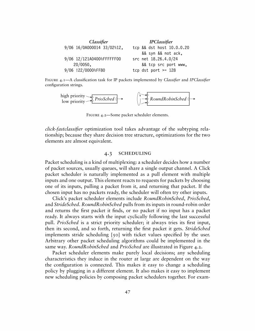
Classifier IPClassifier9/06 16/0A000014 33/02%12, tcp && dst host 10.0.0.20
&& syn && not ack,9/06 12/121A0400%FFFFFF00 src net 18.26.4.0/24
20/0050, && tcp src port www,9/06 !22/0000%FF80 tcp dst port >= 128
Figure 4.1—A classification task for IP packets implemented by Classifier and IPClassifierconfiguration strings.
PrioSchedhigh prioritylow priority RoundRobinSched
Figure 4.2—Some packet scheduler elements.
click-fastclassifier optimization tool takes advantage of the subtyping rela-tionship; because they share decision tree structure, optimizations for the twoelements are almost equivalent.
4.3 scheduling
Packet scheduling is a kind of multiplexing: a scheduler decides how a numberof packet sources, usually queues, will share a single output channel. A Clickpacket scheduler is naturally implemented as a pull element with multipleinputs and one output. This element reacts to requests for packets by choosingone of its inputs, pulling a packet from it, and returning that packet. If thechosen input has no packets ready, the scheduler will often try other inputs.
Click’s packet scheduler elements include RoundRobinSched, PrioSched,and StrideSched. RoundRobinSched pulls from its inputs in round-robin orderand returns the first packet it finds, or no packet if no input has a packetready. It always starts with the input cyclically following the last successfulpull. PrioSched is a strict priority scheduler; it always tries its first input,then its second, and so forth, returning the first packet it gets. StrideSchedimplements stride scheduling [50] with ticket values specified by the user.Arbitrary other packet scheduling algorithms could be implemented in thesame way. RoundRobinSched and PrioSched are illustrated in Figure 4.2.
Packet scheduler elements make purely local decisions; any schedulingcharacteristics they induce in the router at large are dependent on the waythe configuration is connected. This makes it easy to change a schedulingpolicy by plugging in a different element. It also makes it easy to implementnew scheduling policies by composing packet schedulers together. For exam-
47
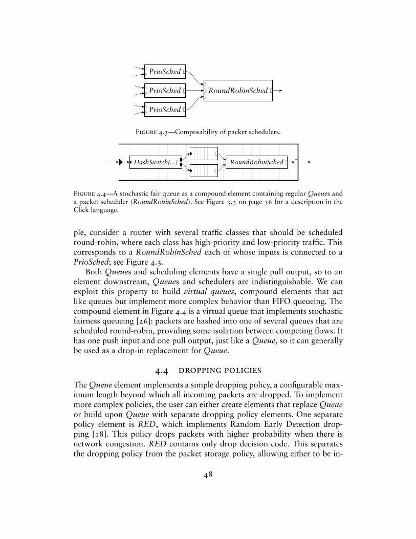
RoundRobinSched
PrioSched
PrioSched
PrioSched
Figure 4.3—Composability of packet schedulers.
HashSwitch(...) RoundRobinSched
Figure 4.4—A stochastic fair queue as a compound element containing regular Queues anda packet scheduler (RoundRobinSched). See Figure 3.3 on page 36 for a description in theClick language.
ple, consider a router with several traffic classes that should be scheduledround-robin, where each class has high-priority and low-priority traffic. Thiscorresponds to a RoundRobinSched each of whose inputs is connected to aPrioSched; see Figure 4.3.
Both Queues and scheduling elements have a single pull output, so to anelement downstream, Queues and schedulers are indistinguishable. We canexploit this property to build virtual queues, compound elements that actlike queues but implement more complex behavior than FIFO queueing. Thecompound element in Figure 4.4 is a virtual queue that implements stochasticfairness queueing [26]: packets are hashed into one of several queues that arescheduled round-robin, providing some isolation between competing flows. Ithas one push input and one pull output, just like a Queue, so it can generallybe used as a drop-in replacement for Queue.
4.4 dropping policies
The Queue element implements a simple dropping policy, a configurable max-imum length beyond which all incoming packets are dropped. To implementmore complex policies, the user can either create elements that replace Queueor build upon Queue with separate dropping policy elements. One separatepolicy element is RED, which implements Random Early Detection drop-ping [18]. This policy drops packets with higher probability when there isnetwork congestion. RED contains only drop decision code. This separatesthe dropping policy from the packet storage policy, allowing either to be in-
48
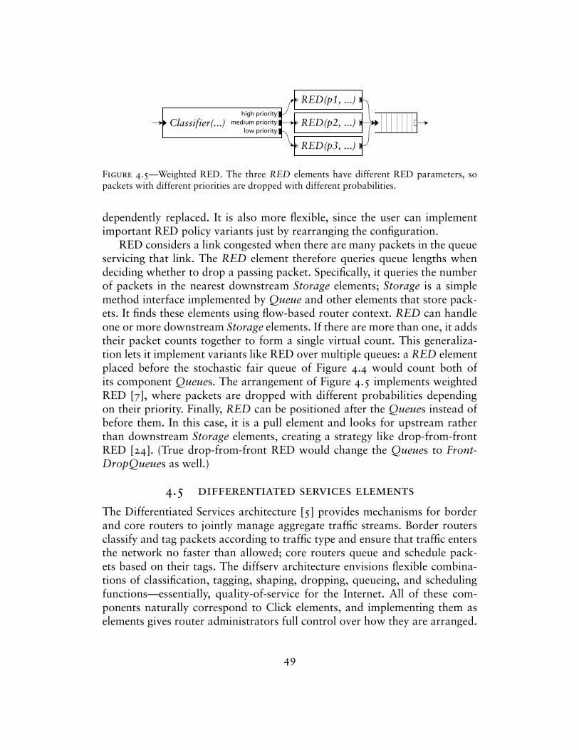
RED(p1, ...)
RED(p2, ...)
RED(p3, ...)
Classifier(...)high priority
medium prioritylow priority
Figure 4.5—Weighted RED. The three RED elements have different RED parameters, sopackets with different priorities are dropped with different probabilities.
dependently replaced. It is also more flexible, since the user can implementimportant RED policy variants just by rearranging the configuration.
RED considers a link congested when there are many packets in the queueservicing that link. The RED element therefore queries queue lengths whendeciding whether to drop a passing packet. Specifically, it queries the numberof packets in the nearest downstream Storage elements; Storage is a simplemethod interface implemented by Queue and other elements that store pack-ets. It finds these elements using flow-based router context. RED can handleone or more downstream Storage elements. If there are more than one, it addstheir packet counts together to form a single virtual count. This generaliza-tion lets it implement variants like RED over multiple queues: a RED elementplaced before the stochastic fair queue of Figure 4.4 would count both ofits component Queues. The arrangement of Figure 4.5 implements weightedRED [7], where packets are dropped with different probabilities dependingon their priority. Finally, RED can be positioned after the Queues instead ofbefore them. In this case, it is a pull element and looks for upstream ratherthan downstream Storage elements, creating a strategy like drop-from-frontRED [24]. (True drop-from-front RED would change the Queues to Front-DropQueues as well.)
4.5 differentiated services elements
The Differentiated Services architecture [5] provides mechanisms for borderand core routers to jointly manage aggregate traffic streams. Border routersclassify and tag packets according to traffic type and ensure that traffic entersthe network no faster than allowed; core routers queue and schedule pack-ets based on their tags. The diffserv architecture envisions flexible combina-tions of classification, tagging, shaping, dropping, queueing, and schedulingfunctions—essentially, quality-of-service for the Internet. All of these com-ponents naturally correspond to Click elements, and implementing them aselements gives router administrators full control over how they are arranged.
49
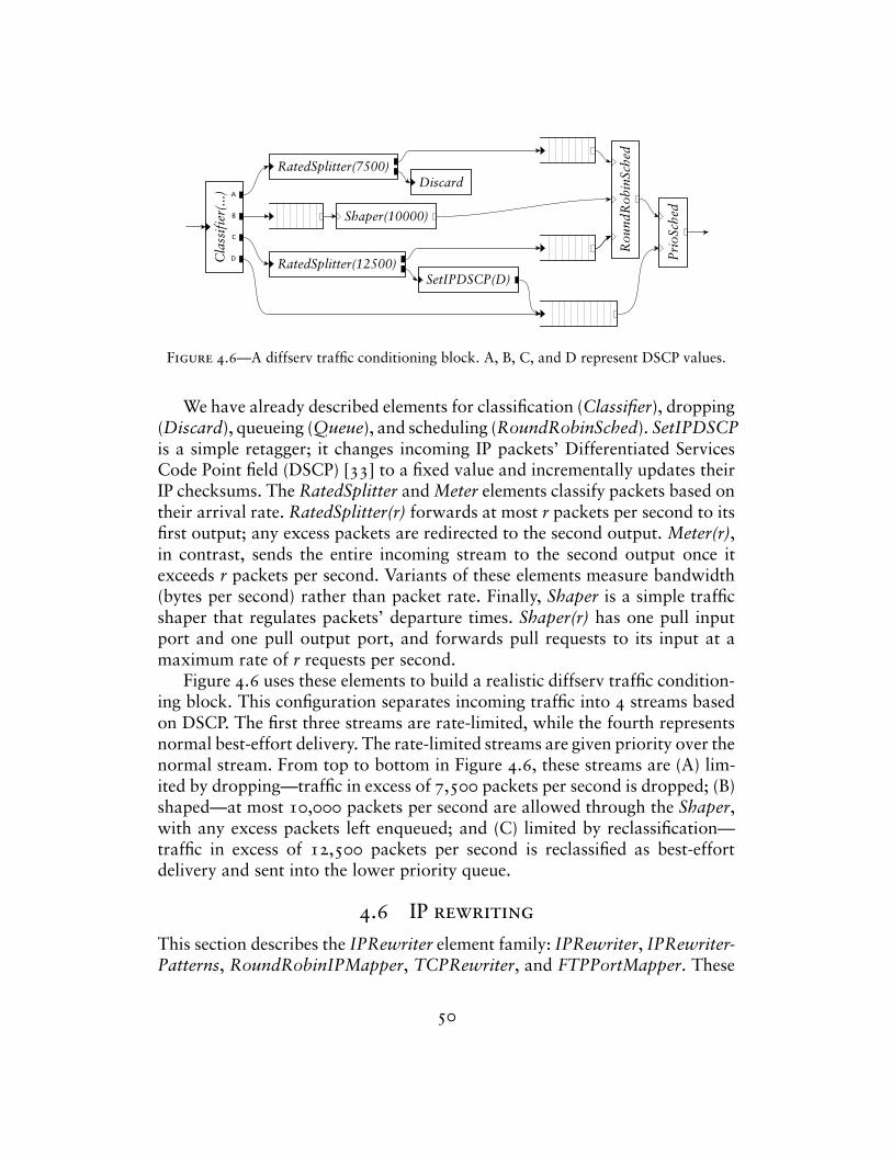
Cla
ssif
ier(
...)
RatedSplitter(7500)Discard
Shaper(10000)
RatedSplitter(12500)
Rou
ndR
obin
Sche
d
Pri
oSch
ed
SetIPDSCP(D)
A
B
C
D
Figure 4.6—A diffserv traffic conditioning block. A, B, C, and D represent DSCP values.
We have already described elements for classification (Classifier), dropping(Discard), queueing (Queue), and scheduling (RoundRobinSched). SetIPDSCPis a simple retagger; it changes incoming IP packets’ Differentiated ServicesCode Point field (DSCP) [33] to a fixed value and incrementally updates theirIP checksums. The RatedSplitter and Meter elements classify packets based ontheir arrival rate. RatedSplitter(r) forwards at most r packets per second to itsfirst output; any excess packets are redirected to the second output. Meter(r),in contrast, sends the entire incoming stream to the second output once itexceeds r packets per second. Variants of these elements measure bandwidth(bytes per second) rather than packet rate. Finally, Shaper is a simple trafficshaper that regulates packets’ departure times. Shaper(r) has one pull inputport and one pull output port, and forwards pull requests to its input at amaximum rate of r requests per second.
Figure 4.6 uses these elements to build a realistic diffserv traffic condition-ing block. This configuration separates incoming traffic into 4 streams basedon DSCP. The first three streams are rate-limited, while the fourth representsnormal best-effort delivery. The rate-limited streams are given priority over thenormal stream. From top to bottom in Figure 4.6, these streams are (A) lim-ited by dropping—traffic in excess of 7,500 packets per second is dropped; (B)shaped—at most 10,000 packets per second are allowed through the Shaper,with any excess packets left enqueued; and (C) limited by reclassification—traffic in excess of 12,500 packets per second is reclassified as best-effortdelivery and sent into the lower priority queue.
4.6 IP rewriting
This section describes the IPRewriter element family: IPRewriter, IPRewriter-Patterns, RoundRobinIPMapper, TCPRewriter, and FTPPortMapper. These
50
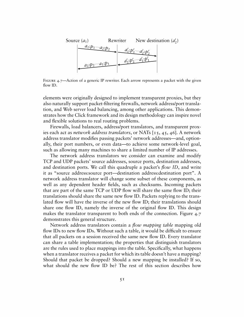
Source (a1) Rewriter New destination (a′2)a1:p1—a2:p2 a′1:p′1—a′2:p′2
a′2:p′2—a′1:p
′1
a2:p2—a1:p1
Figure 4.7—Action of a generic IP rewriter. Each arrow represents a packet with the givenflow ID.
elements were originally designed to implement transparent proxies, but theyalso naturally support packet-filtering firewalls, network address/port transla-tion, and Web server load balancing, among other applications. This demon-strates how the Click framework and its design methodology can inspire noveland flexible solutions to real routing problems.
Firewalls, load balancers, address/port translators, and transparent prox-ies each act as network address translators, or NATs [15, 45, 46]. A networkaddress translator modifies passing packets’ network addresses—and, option-ally, their port numbers, or even data—to achieve some network-level goal,such as allowing many machines to share a limited number of IP addresses.
The network address translators we consider can examine and modifyTCP and UDP packets’ source addresses, source ports, destination addresses,and destination ports. We call this quadruple a packet’s flow ID, and writeit as “source address:source port—destination address:destination port”. Anetwork address translator will change some subset of these components, aswell as any dependent header fields, such as checksums. Incoming packetsthat are part of the same TCP or UDP flow will share the same flow ID; theirtranslations should share the same new flow ID. Packets replying to the trans-lated flow will have the inverse of the new flow ID; their translations shouldshare one flow ID, namely the inverse of the original flow ID. This designmakes the translator transparent to both ends of the connection. Figure 4.7demonstrates this general structure.
Network address translators contain a flow mapping table mapping oldflow IDs to new flow IDs. Without such a table, it would be difficult to ensurethat all packets on a session received the same new flow ID. Every translatorcan share a table implementation; the properties that distinguish translatorsare the rules used to place mappings into the table. Specifically, what happenswhen a translator receives a packet for which its table doesn’t have a mapping?Should that packet be dropped? Should a new mapping be installed? If so,what should the new flow ID be? The rest of this section describes how
51
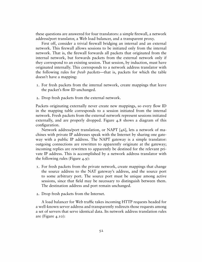
these questions are answered for four translators: a simple firewall, a networkaddress/port translator, a Web load balancer, and a transparent proxy.
First off, consider a trivial firewall bridging an internal and an externalnetwork. This firewall allows sessions to be initiated only from the internalnetwork. That is, the firewall forwards all packets that originated from theinternal network, but forwards packets from the external network only ifthey correspond to an existing session. That session, by induction, must haveoriginated internally. This corresponds to a network address translator withthe following rules for fresh packets—that is, packets for which the tabledoesn’t have a mapping:
1. For fresh packets from the internal network, create mappings that leavethe packet’s flow ID unchanged.
2. Drop fresh packets from the external network.
Packets originating externally never create new mappings, so every flow IDin the mapping table corresponds to a session initiated from the internalnetwork. Fresh packets from the external network represent sessions initiatedexternally, and are properly dropped. Figure 4.8 shows a diagram of thisconfiguration.
Network address/port translation, or NAPT [46], lets a network of ma-chines with private IP addresses speak with the Internet by sharing one gate-way with a public IP address. The NAPT gateway is a simple translator:outgoing connections are rewritten to apparently originate at the gateway;incoming replies are rewritten to apparently be destined for the relevant pri-vate IP address. This is accomplished by a network address translator withthe following rules (Figure 4.9):
1. For fresh packets from the private network, create mappings that changethe source address to the NAT gateway’s address, and the source portto some arbitrary port. The source port must be unique among activesessions, since that field may be necessary to distinguish between them.The destination address and port remain unchanged.
2. Drop fresh packets from the Internet.
A load balancer for Web traffic takes incoming HTTP requests headed fora well-known server address and transparently redirects those requests amonga set of servers that serve identical data. Its network address translation rulesare (Figure 4.10):
52
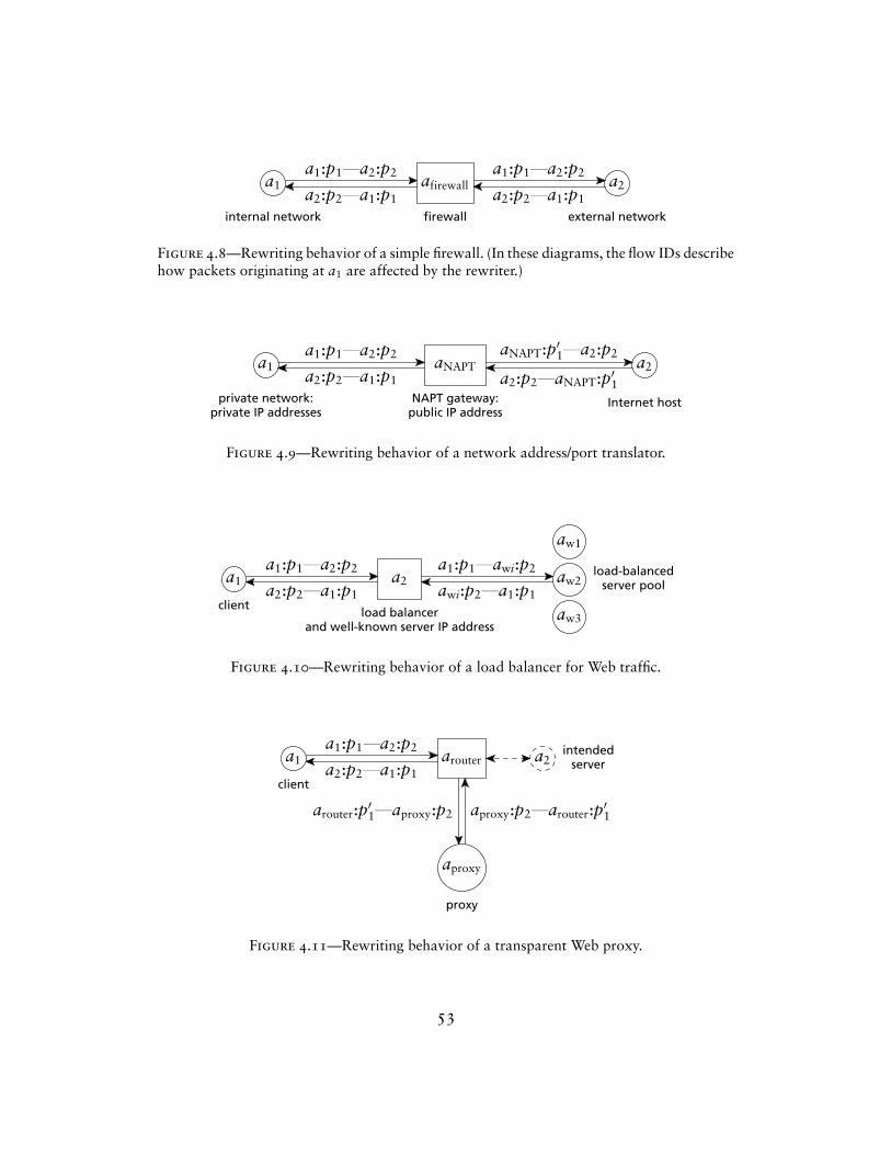
a1 afirewall a2a1:p1—a2:p2
a2:p2—a1:p1
a1:p1—a2:p2
a2:p2—a1:p1
internal network firewall external network
Figure 4.8—Rewriting behavior of a simple firewall. (In these diagrams, the flow IDs describehow packets originating at a1 are affected by the rewriter.)
a1 aNAPT a2a1:p1—a2:p2
a2:p2—a1:p1
aNAPT:p′1—a2:p2
a2:p2—aNAPT:p′1private network:
private IP addressesNAPT gateway:
public IP addressInternet host
Figure 4.9—Rewriting behavior of a network address/port translator.
a1 a2
aw1
aw2
aw3
a1:p1—a2:p2
a2:p2—a1:p1
a1:p1—awi:p2
awi:p2—a1:p1client
load balancerand well-known server IP address
load-balancedserver pool
Figure 4.10—Rewriting behavior of a load balancer for Web traffic.
a1
aproxy
arouter a2a1:p1—a2:p2
a2:p2—a1:p1
arouter:p′1—aproxy:p2 aproxy:p2—arouter:p′1
client
proxy
intendedserver
Figure 4.11—Rewriting behavior of a transparent Web proxy.
53
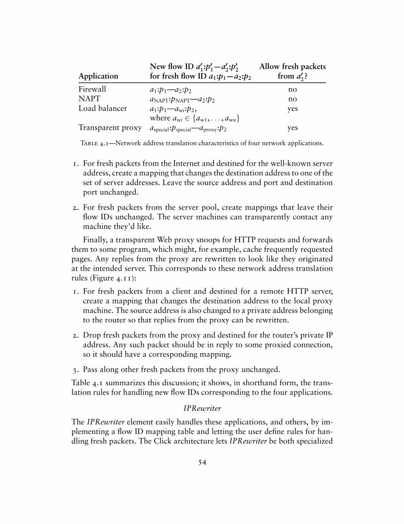
New flow ID a�
1:p�
1—a�
2:p�
2 Allow fresh packetsApplication for fresh flow ID a1:p1—a2:p2 from a
�
2?
Firewall a1:p1—a2:p2 noNAPT aNAPT:pNAPT—a2:p2 noLoad balancer a1:p1—awi:p2, yes
where awi ∈ {aw1, . . . , awn}Transparent proxy aspecial:pspecial—aproxy:p2 yes
Table 4.1—Network address translation characteristics of four network applications.
1. For fresh packets from the Internet and destined for the well-known serveraddress, create a mapping that changes the destination address to one of theset of server addresses. Leave the source address and port and destinationport unchanged.
2. For fresh packets from the server pool, create mappings that leave theirflow IDs unchanged. The server machines can transparently contact anymachine they’d like.
Finally, a transparent Web proxy snoops for HTTP requests and forwardsthem to some program, which might, for example, cache frequently requestedpages. Any replies from the proxy are rewritten to look like they originatedat the intended server. This corresponds to these network address translationrules (Figure 4.11):
1. For fresh packets from a client and destined for a remote HTTP server,create a mapping that changes the destination address to the local proxymachine. The source address is also changed to a private address belongingto the router so that replies from the proxy can be rewritten.
2. Drop fresh packets from the proxy and destined for the router’s private IPaddress. Any such packet should be in reply to some proxied connection,so it should have a corresponding mapping.
3. Pass along other fresh packets from the proxy unchanged.
Table 4.1 summarizes this discussion; it shows, in shorthand form, the trans-lation rules for handling new flow IDs corresponding to the four applications.
IPRewriter
The IPRewriter element easily handles these applications, and others, by im-plementing a flow ID mapping table and letting the user define rules for han-dling fresh packets. The Click architecture lets IPRewriter be both specialized
54
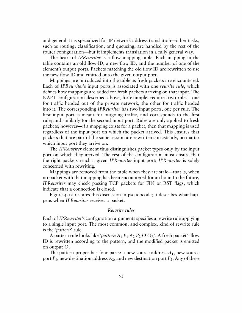
and general. It is specialized for IP network address translation—other tasks,such as routing, classification, and queueing, are handled by the rest of therouter configuration—but it implements translation in a fully general way.
The heart of IPRewriter is a flow mapping table. Each mapping in thetable contains an old flow ID, a new flow ID, and the number of one of theelement’s output ports. Packets matching the old flow ID are rewritten to usethe new flow ID and emitted onto the given output port.
Mappings are introduced into the table as fresh packets are encountered.Each of IPRewriter’s input ports is associated with one rewrite rule, whichdefines how mappings are added for fresh packets arriving on that input. TheNAPT configuration described above, for example, requires two rules—onefor traffic headed out of the private network, the other for traffic headedinto it. The corresponding IPRewriter has two input ports, one per rule. Thefirst input port is meant for outgoing traffic, and corresponds to the firstrule; and similarly for the second input port. Rules are only applied to freshpackets, however—if a mapping exists for a packet, then that mapping is usedregardless of the input port on which the packet arrived. This ensures thatpackets that are part of the same session are rewritten consistently, no matterwhich input port they arrive on.
The IPRewriter element thus distinguishes packet types only by the inputport on which they arrived. The rest of the configuration must ensure thatthe right packets reach a given IPRewriter input port; IPRewriter is solelyconcerned with rewriting.
Mappings are removed from the table when they are stale—that is, whenno packet with that mapping has been encountered for an hour. In the future,IPRewriter may check passing TCP packets for FIN or RST flags, whichindicate that a connection is closed.
Figure 4.12 restates this discussion in pseudocode; it describes what hap-pens when IPRewriter receives a packet.
Rewrite rules
Each of IPRewriter’s configuration arguments specifies a rewrite rule applyingto a single input port. The most common, and complex, kind of rewrite ruleis the ‘pattern’ rule.
A pattern rule looks like ‘pattern A1 P1 A2 P2 O OR’. A fresh packet’s flowID is rewritten according to the pattern, and the modified packet is emittedon output O.
The pattern proper has four parts: a new source address A1, new sourceport P1, new destination address A2, and new destination port P2. Any of these
55

For each packet p received on input port i,Search the flow mapping table for a mapping m
corresponding to p’s flow IDIf no mapping was found,
Execute the rewrite rule for input port i(The rule may insert new mappings into the table.)Search the table again for mapping m
If no mapping was found either time,Drop the packet
Otherwise, (m is a valid mapping)Rewrite p’s flow ID according to mPush p onto the output port specified by m
Figure 4.12—Pseudocode describing how IPRewriter behaves when a packet is received.
parts can be a dash ‘–’, which means “leave unchanged”. Thus, the pattern‘1.0.0.1 – 1.0.0.2 –’ will set the packet’s source and destination addresses butleave the ports as they are. The source port specification can also be a rangeof ports ‘PL–PH’, in which case the rewriter will choose a port between PL andPH. It will also ensure that any two active mappings created by this patternhave different source ports. The pattern ‘1.0.0.1 1024–65535 1.0.0.2 80’,for example, sets every fresh packet’s source address to 1.0.0.1, destinationaddress to 1.0.0.2, and destination port to 80. The new source port, however,will differ for any two active sessions. Therefore, the new source port uniquelyidentifies an session, and every reply packet—which will contain that portnumber—can be mapped back to a unique original flow ID.
O is an output port number. The rewritten fresh packet, and later packetswith the same flow ID, are emitted on output port O. The other port number,OR, is used for rewritten reply packets. Different output ports are purelya convenience. IPRewriter assigns no semantics to its output ports—everyrewriter could have exactly one output. It is often useful, however, to haveIPRewriter demultiplex incoming packet streams based on their flow IDs.The user can decide, for example, that packets headed for networks A and Bshould be emitted on a rewriter’s first and second outputs, respectively, andenforce this decision through rewrite rules. IPRewriter is already rewritingpackets; demultiplexing has considerable benefit and minute additional cost.
When a fresh packet with flow ID a1:p1—a2:p2 arrives on an input portwith a ‘pattern’ rule, the rewriter first chooses a new flow ID a′1:p′1—a′2:p′2according to the pattern. Next, the following pair of mappings is installed,one for the input flow ID and one for replies to the new flow ID:
56
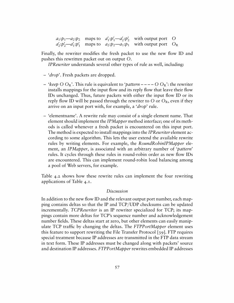
a1:p1—a2:p2 maps to a′1:p′1—a′2:p′2 with output port Oa′2:p′2—a′1:p′1 maps to a2:p2—a1:p1 with output port OR
Finally, the rewriter modifies the fresh packet to use the new flow ID andpushes this rewritten packet out on output O.
IPRewriter understands several other types of rule as well, including:
– ‘drop’. Fresh packets are dropped.
– ‘keep O OR’. This rule is equivalent to ‘pattern – – – – O OR’: the rewriterinstalls mappings for the input flow and its reply flow that leave their flowIDs unchanged. Thus, future packets with either the input flow ID or itsreply flow ID will be passed through the rewriter to O or OR, even if theyarrive on an input port with, for example, a ‘drop’ rule.
– ‘elementname’. A rewrite rule may consist of a single element name. Thatelement should implement the IPMapper method interface; one of its meth-ods is called whenever a fresh packet is encountered on this input port.The method is expected to install mappings into the IPRewriter element ac-cording to some algorithm. This lets the user extend the available rewriterules by writing elements. For example, the RoundRobinIPMapper ele-ment, an IPMapper, is associated with an arbitrary number of ‘pattern’rules. It cycles through these rules in round-robin order as new flow IDsare encountered. This can implement round-robin load balancing amonga pool of Web servers, for example.
Table 4.2 shows how these rewrite rules can implement the four rewritingapplications of Table 4.1.
Discussion
In addition to the new flow ID and the relevant output port number, each map-ping contains deltas so that the IP and TCP/UDP checksums can be updatedincrementally. TCPRewriter is an IP rewriter specialized for TCP; its map-pings contain more deltas for TCP’s sequence number and acknowledgementnumber fields. These deltas start at zero, but other elements can easily manip-ulate TCP traffic by changing the deltas. The FTPPortMapper element usesthis feature to support rewriting the File Transfer Protocol [39]. FTP requiresspecial treatment because IP addresses are transmitted in the FTP data streamin text form. These IP addresses must be changed along with packets’ sourceand destination IP addresses. FTPPortMapper rewrites embedded IP addresses
57
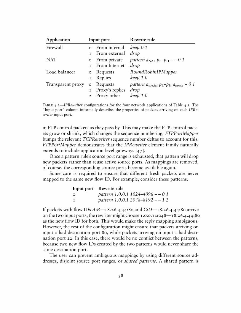
Application Input port Rewrite rule
Firewall 0 From internal keep 0 11 From external drop
NAT 0 From private pattern aNAT pL–pH – – 0 11 From Internet drop
Load balancer 0 Requests RoundRobinIPMapper1 Replies keep 1 0
Transparent proxy 0 Requests pattern aspecial pL–pH aproxy – 0 11 Proxy’s replies drop2 Proxy other keep 1 0
Table 4.2—IPRewriter configurations for the four network applications of Table 4.1. The“Input port” column informally describes the properties of packets arriving on each IPRe-writer input port.
in FTP control packets as they pass by. This may make the FTP control pack-ets grow or shrink, which changes the sequence numbering; FTPPortMapperbumps the relevant TCPRewriter sequence number deltas to account for this.FTPPortMapper demonstrates that the IPRewriter element family naturallyextends to include application-level gateways [47].
Once a pattern rule’s source port range is exhausted, that pattern will dropnew packets rather than reuse active source ports. As mappings are removed,of course, the corresponding source ports become available again.
Some care is required to ensure that different fresh packets are nevermapped to the same new flow ID. For example, consider these patterns:
Input port Rewrite rule0 pattern 1.0.0.1 1024–4096 – – 0 11 pattern 1.0.0.1 2048–8192 – – 1 2
If packets with flow IDs A:B—18.26.4.44:80 and C:D—18.26.4.44:80 arriveon the two input ports, the rewriter might choose 1.0.0.1:2048—18.26.4.44:80as the new flow ID for both. This would make the reply mapping ambiguous.However, the rest of the configuration might ensure that packets arriving oninput 0 had destination port 80, while packets arriving on input 1 had desti-nation port 22. In this case, there would be no conflict between the patterns,because two new flow IDs created by the two patterns would never share thesame destination port.
The user can prevent ambiguous mappings by using different source ad-dresses, disjoint source port ranges, or shared patterns. A shared pattern is
58
not tied to a particular rule; instead, multiple IPRewriter rules can refer to thesame shared pattern. Any two mappings created by using shared pattern willuse different source ports, even if the mappings are stored in different IPRe-writer elements. Shared patterns are specified with an information element,IPRewriterPatterns.
The network can generate ICMP errors, such as Destination Unreachable,Network Unreachable, and so forth, in response to any IP packet. If the ICMPerror packet was generated in response to a rewritten packet, then it willnot reach the original sender unaided. IPRewriter itself cannot help directlybecause the error packet is not TCP or UDP. The natural solution is to buildan application-level gateway for ICMP. The ICMPRewriter element rewritesICMP error packets based on the mappings stored in an existing IPRewriter.
This section has presented the IPRewriter element family in isolation.These elements shine most, however, when combined with other elementsto form router configurations. Click element characteristics and our elementdesign principles have led to uniquely flexible and modular components forIP network address translation. Users can create arbitrarily complex rewritingspecifications; because of Click’s input and output ports, their intentions arestill clear. IPRewriter and friends are more flexible than other network addresstranslators [21, 40]. For example, IPRewriter seems unique in its support formultiple translation tables and flexible placement of translation relative toother routing tasks. Section 5.5 presents an IPRewriter element in the contextof a transparent Web proxy configuration.
4.7 information elements
The elements described so far, like most of Click’s elements, participate ac-tively in packet forwarding. However, some elements do not naturally forwardpackets. For example, shared IPRewriter patterns do not concern packets atall. Other shared structures, such as certain routing or location tables, alsomight belong outside the flow of packets. Furthermore, most potential lan-guage extensions do not involve forwarding packets, as Click already hasgood support for forwarding.
Shared state and language extensions are implemented in Click by in-formation elements, which have no inputs or outputs. Information elementsare a general mechanism for representing router structure that is indepen-dent of packet flow. Click’s extensibility depends on decent support for non-forwarding tasks, so this section describes several information elements indepth, demonstrating the range of extensions they can implement.
Some information elements specify properties of other elements in the
59
configuration. Elements in this group are not active at runtime; they collectinformation from their configuration strings into a simple database that otherelements can easily access. The ScheduleInfo element, for example, storesinformation about scheduling parameters. Section 2.6 described the task queuethat schedules Click elements. Each scheduled element has a number of ticketsthat determines how often it will be scheduled in relation to other tasks; anelement with two tickets will be scheduled twice as often as an element withone. Users specify these ticket amounts with ScheduleInfo.
Each of ScheduleInfo’s configuration arguments contains an element nameand that element’s relative priority. The default priority is 1; a priority of 2says that an element should be scheduled twice as often as the default, 0.5says it should be scheduled half as often, and so forth. For example:
fd :: FromDevice(eth0); td :: ToDevice(eth0);ScheduleInfo(fd 0.1, td 1);
Elements like ScheduleInfo share a common problem: how should com-pound elements and information elements interact? This question is tricky toanswer well, but finding the right solution can enhance the compound elementabstraction. Consider the following configuration, where an element that mustbe scheduled (Unqueue) is buried inside a compound element (Delayer):
elementclass Delayer {input -> Queue -> u :: Unqueue -> output;
}... -> d :: Delayer -> ...
Who can provide scheduling parameters for the Unqueue—the compoundelement, the main configuration, or both? And if both can provide parameters,how should those parameters interact?
In Click, both the compound element and the main configuration canprovide scheduling parameters. For example:
elementclass Delayer {input -> Queue -> u :: Unqueue -> output;ScheduleInfo(u 2);
}... -> d :: Delayer -> ...ScheduleInfo(d 0.8);
This configuration will be flattened to something like the following.
60
d/Queue@1 :: Queue;d/u :: Unqueue;d/ScheduleInfo@3 :: ScheduleInfo(u 2);ScheduleInfo@10 :: ScheduleInfo(d 0.8);... -> d/Queue@1 -> d/u -> ...
Every element inside the compound, including the ScheduleInfo, has been as-signed a name prefixed with d/. The ScheduleInfo named d/ScheduleInfo@3takes note of this and adds its d/ prefix to each of its arguments; thus, itsargument is effectively d/u 2, not u 2. The user can also specify a schedul-ing parameter for a prefix, such as d 0.8 in the example. This parameteris multiplied with parameters specified inside the prefix. Therefore, in thisconfiguration, the d/u element will have scheduling priority 0.8 × 2 = 1.6.Compound element designers and users collaborate to set scheduling param-eters in this design. A compound element can suggest that it be scheduledmore or less often than the default; if the user does not specify a schedulingparameter, Click will follow the element’s suggestion.
In an alternative design, compound elements might specify how their partsshould be scheduled relative to one another, but only the main configurationcould say how the compound should be scheduled relative to other elements.The chosen design might be viewed as a breach of encapsulation when com-pared to this alternative. However, the chosen design is more flexible, thatflexibility is important in practice, and the alternative design breaches en-capsulation even more. With Click’s design, a compound element is trulyequivalent to the corresponding collection of simple elements; if two schedu-lable elements with priority 1 are included in a compound, their schedulingparameters are the same as before. In the alternative design, their effective pri-orities would drop to 0.5, since the compound as a whole would have priority1. To make the compound usable, then, every user would have to give everyuse of the compound twice the scheduling parameter they might expect.
Other information elements extend the language’s syntax. For example,Click configurations often refer to common IP addresses, Ethernet addresses,and IP network prefixes repeatedly. The AddressInfo element can provideshorthand names for these addresses, localizing the addresses and makingthe configuration easy to adapt as addresses change. Each of AddressInfo’sconfiguration arguments has a name and several addresses; for example,
AddressInfo(me 18.26.4.15 0:90:27:97:5a:76);
says that ‘me’ is shorthand for an IP address (18.26.4.15) and an Ethernetaddress (0:90:27:97:5a:76). The address type chosen for a particular use of‘me’ depends on the kind of address required there.
61
Some information elements monitor the router configuration at run timeor respond to user requests. For instance, PeekHandlers and PokeHandlerscall read and write handlers on specified elements at specified times; this isuseful for running repeatable tests. The ControlSocket element, available onlyin the user-level driver, opens a TCP/IP socket and listens for commands.Other programs may connect to this socket to query read handlers, call writehandlers, or find out other information about the current router. Still otherinformation elements stop the router when packet sources have completed,poll network interface status, or set up performance counter measurements.
Language extensions in general are well suited for implementation by infor-mation elements. When implemented as elements, extensions fit into the Clicklanguage without change, interact naturally with compound element classes,and, given anonymous element declarations, still provide convenient, read-able syntax. Some extensions do not fit well into this framework—compoundelement classes, for example, obviously could not be implemented by infor-mation elements alone. However, most extensions do not alter the elementabstraction, they merely augment it. Information elements are good for ex-tensions of this kind. They make the Click language and system extensiblewithout pain.
62
5Routers
Now that elements have been described, we explore how they combine to formrouters. This chapter presents several full Click router configurations, startingwith a standards-compliant IP router. The Click IP router is modular—it hassixteen elements on its forwarding path—and, therefore, easy to understandand easy to extend. The next sections present IP router extensions for differentqueueing and packet scheduling policies and for transparent proxying, aswell as simpler configurations that use subsets of the IP router’s elements.Of course, Click is suitable for many packet processing tasks other than IProuting, and the chapter closes with examples of non-IP configurations and IPnon-routers—specifically, an Ethernet switch, a simple firewall, and the trafficgenerator used in our tests.
5.1 IP router
Figure 5.1 shows a Click IP router that forwards unicast packets in nearlyfull compliance with the standards [3, 37, 38]. The version in the figure hastwo network interfaces, but easily generalizes to three or more. The rest ofthis section describes this configuration in more detail; Chapter 8 evaluates itsperformance with eight network interfaces, and Appendix A contains quickdescriptions of every element class it uses.
IP forwarding tasks that involve only local information fit naturally intothe Click framework. For example, DecIPTTL decides if a packet’s time-to-live field (TTL) has expired. If the TTL is still valid, DecIPTTL decrementsit, incrementally updates the packet’s checksum, and emits the packet on itsfirst output; if the TTL has expired, DecIPTTL emits the packet on its secondoutput, which is usually connected to an element that generates ICMP errors.These actions depend only on the packet’s contents, and do not interact withdecisions made elsewhere except as expressed in the packet’s path throughthe element graph. Self-contained elements like DecIPTTL can be easily com-
63
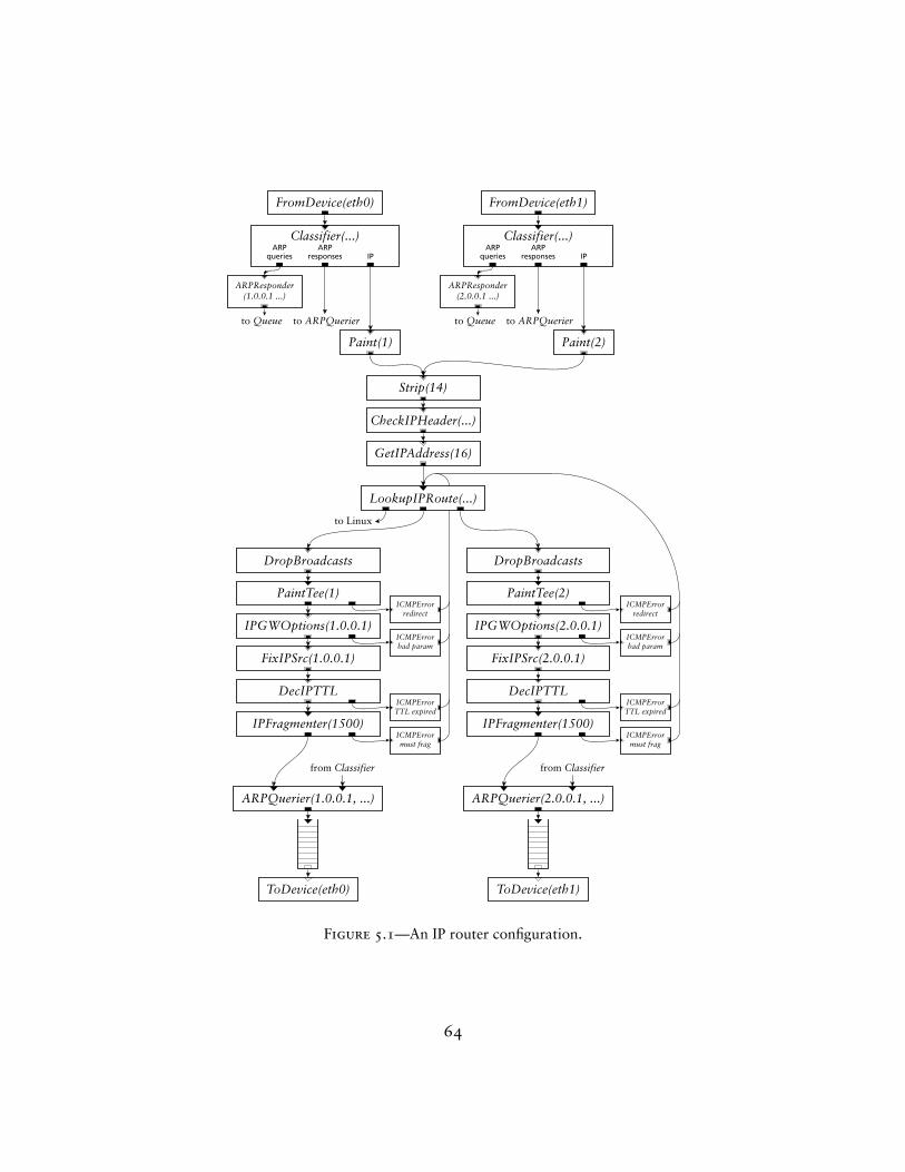
FromDevice(eth0) FromDevice(eth1)
Classifier(...) Classifier(...)
ARPQuerier(1.0.0.1, ...)
ToDevice(eth0)
ARPQuerier(2.0.0.1, ...)
ToDevice(eth1)
ARPResponder(1.0.0.1 ...)
ARPResponder(2.0.0.1 ...)
IPGWOptions(1.0.0.1)
IPFragmenter(1500)
DecIPTTL
FixIPSrc(1.0.0.1)
PaintTee(1)
DropBroadcasts
ICMPErrorredirect
ICMPErrorbad param
ICMPErrorTTL expired
ICMPErrormust frag
IPGWOptions(2.0.0.1)
IPFragmenter(1500)
DecIPTTL
FixIPSrc(2.0.0.1)
PaintTee(2)
DropBroadcasts
ICMPErrorredirect
ICMPErrorbad param
ICMPErrorTTL expired
ICMPErrormust frag
Paint(1) Paint(2)
Strip(14)
CheckIPHeader(...)
GetIPAddress(16)
LookupIPRoute(...)
ARPqueries
ARPresponses IP
ARPqueries
ARPresponses IP
to Queue to Queueto ARPQuerier to ARPQuerier
from Classifier from Classifier
to Linux
Figure 5.1—An IP router configuration.
64
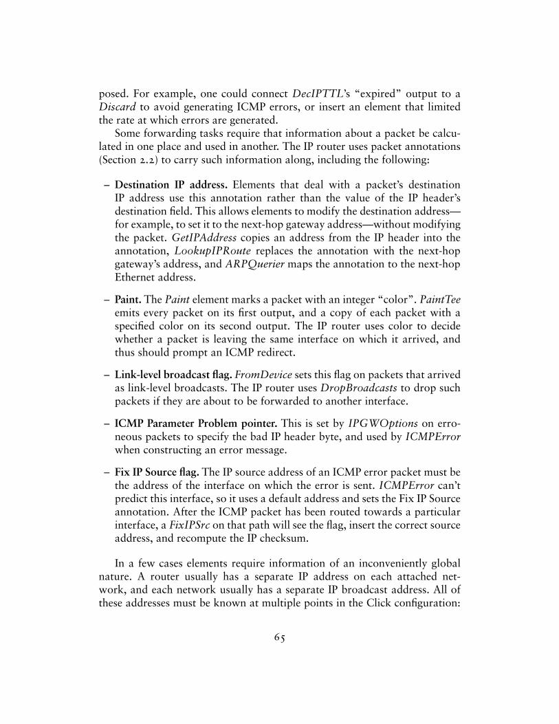
posed. For example, one could connect DecIPTTL’s “expired” output to aDiscard to avoid generating ICMP errors, or insert an element that limitedthe rate at which errors are generated.
Some forwarding tasks require that information about a packet be calcu-lated in one place and used in another. The IP router uses packet annotations(Section 2.2) to carry such information along, including the following:
– Destination IP address. Elements that deal with a packet’s destinationIP address use this annotation rather than the value of the IP header’sdestination field. This allows elements to modify the destination address—for example, to set it to the next-hop gateway address—without modifyingthe packet. GetIPAddress copies an address from the IP header into theannotation, LookupIPRoute replaces the annotation with the next-hopgateway’s address, and ARPQuerier maps the annotation to the next-hopEthernet address.
– Paint. The Paint element marks a packet with an integer “color”. PaintTeeemits every packet on its first output, and a copy of each packet with aspecified color on its second output. The IP router uses color to decidewhether a packet is leaving the same interface on which it arrived, andthus should prompt an ICMP redirect.
– Link-level broadcast flag. FromDevice sets this flag on packets that arrivedas link-level broadcasts. The IP router uses DropBroadcasts to drop suchpackets if they are about to be forwarded to another interface.
– ICMP Parameter Problem pointer. This is set by IPGWOptions on erro-neous packets to specify the bad IP header byte, and used by ICMPErrorwhen constructing an error message.
– Fix IP Source flag. The IP source address of an ICMP error packet must bethe address of the interface on which the error is sent. ICMPError can’tpredict this interface, so it uses a default address and sets the Fix IP Sourceannotation. After the ICMP packet has been routed towards a particularinterface, a FixIPSrc on that path will see the flag, insert the correct sourceaddress, and recompute the IP checksum.
In a few cases elements require information of an inconveniently globalnature. A router usually has a separate IP address on each attached net-work, and each network usually has a separate IP broadcast address. All ofthese addresses must be known at multiple points in the Click configuration:
65
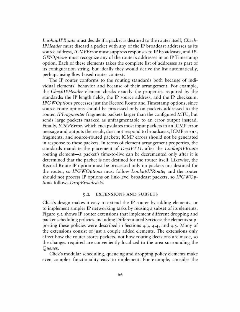
LookupIPRoute must decide if a packet is destined to the router itself, Check-IPHeader must discard a packet with any of the IP broadcast addresses as itssource address, ICMPError must suppress responses to IP broadcasts, and IP-GWOptions must recognize any of the router’s addresses in an IP Timestampoption. Each of these elements takes the complete list of addresses as part ofits configuration string, but ideally they would derive the list automatically,perhaps using flow-based router context.
The IP router conforms to the routing standards both because of indi-vidual elements’ behavior and because of their arrangement. For example,the CheckIPHeader element checks exactly the properties required by thestandards: the IP length fields, the IP source address, and the IP checksum.IPGWOptions processes just the Record Route and Timestamp options, sincesource route options should be processed only on packets addressed to therouter. IPFragmenter fragments packets larger than the configured MTU, butsends large packets marked as unfragmentable to an error output instead.Finally, ICMPError, which encapsulates most input packets in an ICMP errormessage and outputs the result, does not respond to broadcasts, ICMP errors,fragments, and source-routed packets; ICMP errors should not be generatedin response to these packets. In terms of element arrangement properties, thestandards mandate the placement of DecIPTTL after the LookupIPRouterouting element—a packet’s time-to-live can be decremented only after it isdetermined that the packet is not destined for the router itself. Likewise, theRecord Route IP option must be processed only on packets not destined forthe router, so IPGWOptions must follow LookupIPRoute; and the routershould not process IP options on link-level broadcast packets, so IPGWOp-tions follows DropBroadcasts.
5.2 extensions and subsets
Click’s design makes it easy to extend the IP router by adding elements, orto implement simpler IP networking tasks by reusing a subset of its elements.Figure 5.2 shows IP router extensions that implement different dropping andpacket scheduling policies, including Differentiated Services; the elements sup-porting these policies were described in Sections 4.3, 4.4, and 4.5. Many ofthe extensions consist of just a couple added elements. The extensions onlyaffect how the router stores packets, not how routing decisions are made, sothe changes required are conveniently localized to the area surrounding theQueues.
Click’s modular scheduling, queueing and dropping policy elements makeeven complex functionality easy to implement. For example, consider the
66
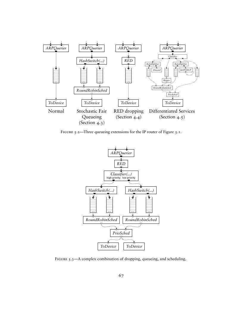
ARPQuerier
ToDevice
ARPQuerier
HashSwitch(...)
RoundRobinSched
ToDevice
ARPQuerier
RED
ToDevice
ARPQuerier
ToDevice
Classifier
RatedSplitter
Discard
Shaper
RatedSplitter
SetIPDSCP
RoundRobinSched
PrioSched
Normal Stochastic Fair RED dropping Differentiated ServicesQueueing (Section 4.4) (Section 4.5)
(Section 4.3)
Figure 5.2—Three queueing extensions for the IP router of Figure 5.1.
ARPQuerier
RED
Classifier(...)
RoundRobinSched RoundRobinSched
HashSwitch(...) HashSwitch(...)
PrioSched
ToDevice ToDevice
high priority low priority
Figure 5.3—A complex combination of dropping, queueing, and scheduling.
67
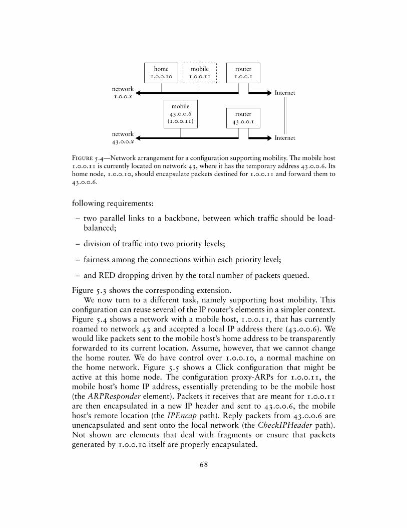
home1.0.0.10
mobile43.0.0.6
(1.0.0.11)router
43.0.0.1
router1.0.0.1
mobile1.0.0.11
network1.0.0.x
network43.0.0.x
Internet
Internet
Figure 5.4—Network arrangement for a configuration supporting mobility. The mobile host1.0.0.11 is currently located on network 43, where it has the temporary address 43.0.0.6. Itshome node, 1.0.0.10, should encapsulate packets destined for 1.0.0.11 and forward them to43.0.0.6.
following requirements:
– two parallel links to a backbone, between which traffic should be load-balanced;
– division of traffic into two priority levels;
– fairness among the connections within each priority level;
– and RED dropping driven by the total number of packets queued.
Figure 5.3 shows the corresponding extension.We now turn to a different task, namely supporting host mobility. This
configuration can reuse several of the IP router’s elements in a simpler context.Figure 5.4 shows a network with a mobile host, 1.0.0.11, that has currentlyroamed to network 43 and accepted a local IP address there (43.0.0.6). Wewould like packets sent to the mobile host’s home address to be transparentlyforwarded to its current location. Assume, however, that we cannot changethe home router. We do have control over 1.0.0.10, a normal machine onthe home network. Figure 5.5 shows a Click configuration that might beactive at this home node. The configuration proxy-ARPs for 1.0.0.11, themobile host’s home IP address, essentially pretending to be the mobile host(the ARPResponder element). Packets it receives that are meant for 1.0.0.11are then encapsulated in a new IP header and sent to 43.0.0.6, the mobilehost’s remote location (the IPEncap path). Reply packets from 43.0.0.6 areunencapsulated and sent onto the local network (the CheckIPHeader path).Not shown are elements that deal with fragments or ensure that packetsgenerated by 1.0.0.10 itself are properly encapsulated.
68
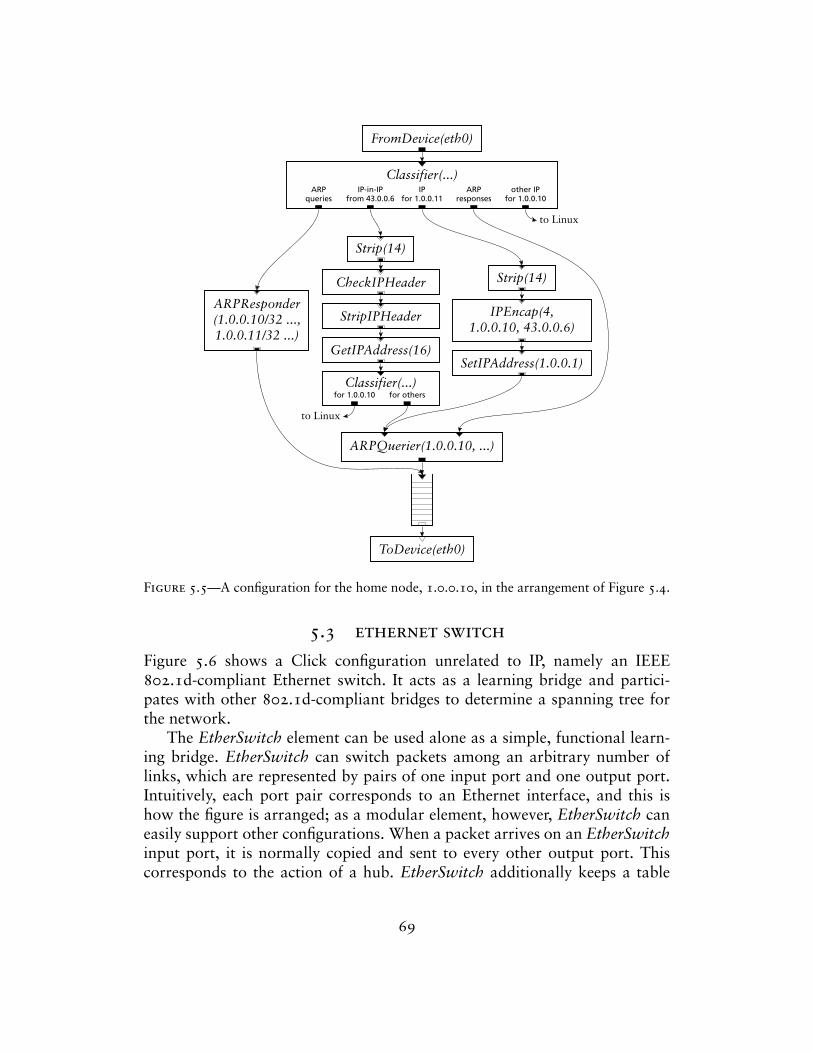
FromDevice(eth0)
ToDevice(eth0)
Classifier(...)
ARPQuerier(1.0.0.10, ...)
ARPResponder(1.0.0.10/32 ...,1.0.0.11/32 ...)
GetIPAddress(16)
StripIPHeader
CheckIPHeader
Strip(14)
Classifier(...)
SetIPAddress(1.0.0.1)
IPEncap(4,1.0.0.10, 43.0.0.6)
Strip(14)
ARPqueries
IP-in-IPfrom 43.0.0.6
IPfor 1.0.0.11
ARPresponses
other IPfor 1.0.0.10
for 1.0.0.10 for others
to Linux
to Linux
Figure 5.5—A configuration for the home node, 1.0.0.10, in the arrangement of Figure 5.4.
5.3 ethernet switch
Figure 5.6 shows a Click configuration unrelated to IP, namely an IEEE802.1d-compliant Ethernet switch. It acts as a learning bridge and partici-pates with other 802.1d-compliant bridges to determine a spanning tree forthe network.
The EtherSwitch element can be used alone as a simple, functional learn-ing bridge. EtherSwitch can switch packets among an arbitrary number oflinks, which are represented by pairs of one input port and one output port.Intuitively, each port pair corresponds to an Ethernet interface, and this ishow the figure is arranged; as a modular element, however, EtherSwitch caneasily support other configurations. When a packet arrives on an EtherSwitchinput port, it is normally copied and sent to every other output port. Thiscorresponds to the action of a hub. EtherSwitch additionally keeps a table
69
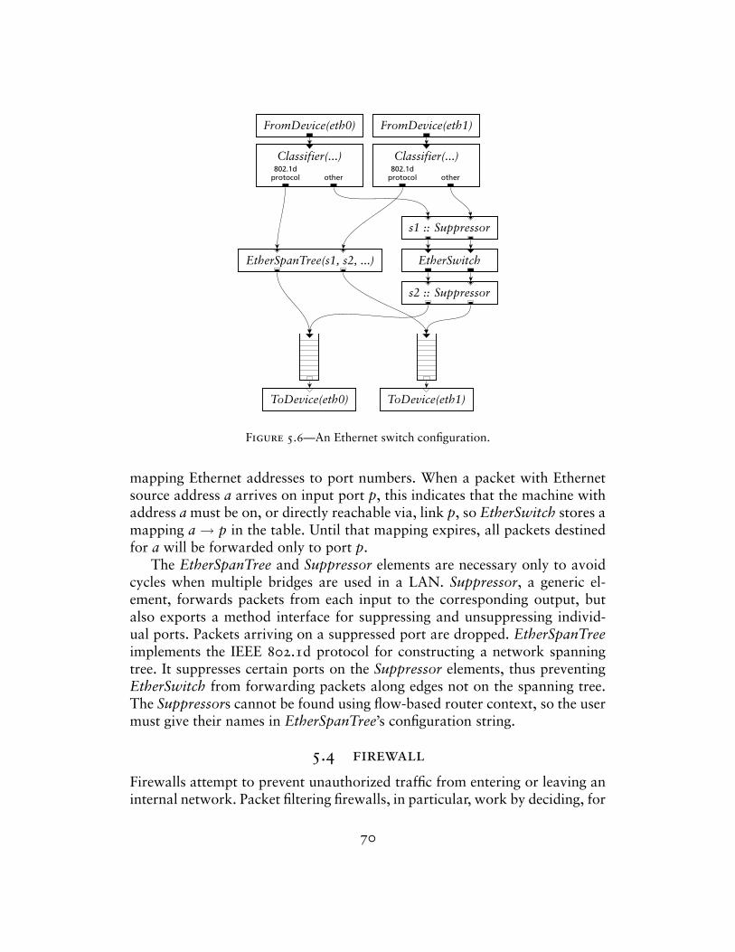
FromDevice(eth0) FromDevice(eth1)
Classifier(...) Classifier(...)
EtherSwitchEtherSpanTree(s1, s2, ...)
s1 :: Suppressor
s2 :: Suppressor
ToDevice(eth0) ToDevice(eth1)
802.1dprotocol other
802.1dprotocol other
Figure 5.6—An Ethernet switch configuration.
mapping Ethernet addresses to port numbers. When a packet with Ethernetsource address a arrives on input port p, this indicates that the machine withaddress a must be on, or directly reachable via, link p, so EtherSwitch stores amapping a → p in the table. Until that mapping expires, all packets destinedfor a will be forwarded only to port p.
The EtherSpanTree and Suppressor elements are necessary only to avoidcycles when multiple bridges are used in a LAN. Suppressor, a generic el-ement, forwards packets from each input to the corresponding output, butalso exports a method interface for suppressing and unsuppressing individ-ual ports. Packets arriving on a suppressed port are dropped. EtherSpanTreeimplements the IEEE 802.1d protocol for constructing a network spanningtree. It suppresses certain ports on the Suppressor elements, thus preventingEtherSwitch from forwarding packets along edges not on the spanning tree.The Suppressors cannot be found using flow-based router context, so the usermust give their names in EtherSpanTree’s configuration string.
5.4 firewall
Firewalls attempt to prevent unauthorized traffic from entering or leaving aninternal network. Packet filtering firewalls, in particular, work by deciding, for
70
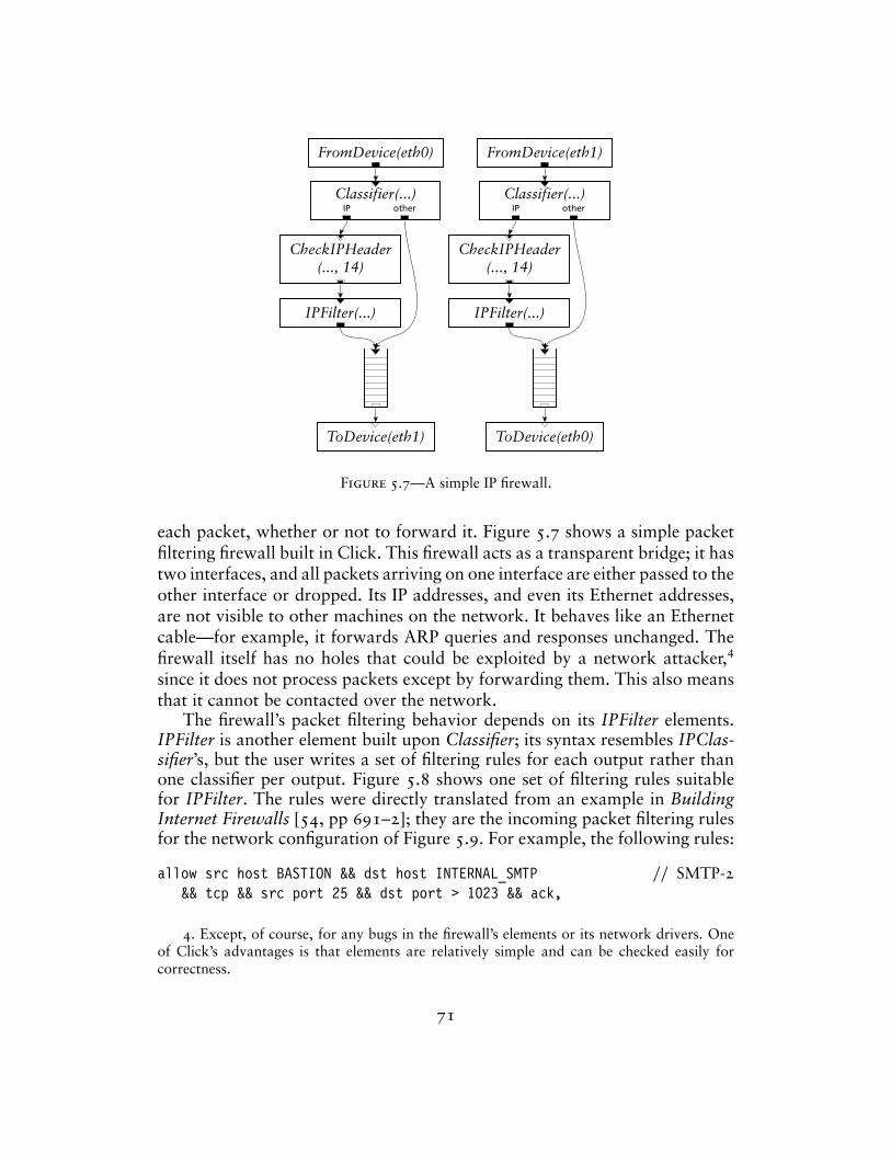
FromDevice(eth0) FromDevice(eth1)
ToDevice(eth0)ToDevice(eth1)
Classifier(...) Classifier(...)
CheckIPHeader(..., 14)
CheckIPHeader(..., 14)
IPFilter(...) IPFilter(...)
IP other IP other
Figure 5.7—A simple IP firewall.
each packet, whether or not to forward it. Figure 5.7 shows a simple packetfiltering firewall built in Click. This firewall acts as a transparent bridge; it hastwo interfaces, and all packets arriving on one interface are either passed to theother interface or dropped. Its IP addresses, and even its Ethernet addresses,are not visible to other machines on the network. It behaves like an Ethernetcable—for example, it forwards ARP queries and responses unchanged. Thefirewall itself has no holes that could be exploited by a network attacker,4
since it does not process packets except by forwarding them. This also meansthat it cannot be contacted over the network.
The firewall’s packet filtering behavior depends on its IPFilter elements.IPFilter is another element built upon Classifier; its syntax resembles IPClas-sifier’s, but the user writes a set of filtering rules for each output rather thanone classifier per output. Figure 5.8 shows one set of filtering rules suitablefor IPFilter. The rules were directly translated from an example in BuildingInternet Firewalls [54, pp 691–2]; they are the incoming packet filtering rulesfor the network configuration of Figure 5.9. For example, the following rules:
allow src host BASTION && dst host INTERNAL_SMTP // SMTP-2&& tcp && src port 25 && dst port > 1023 && ack,
4. Except, of course, for any bugs in the firewall’s elements or its network drivers. Oneof Click’s advantages is that elements are relatively simple and can be checked easily forcorrectness.
71
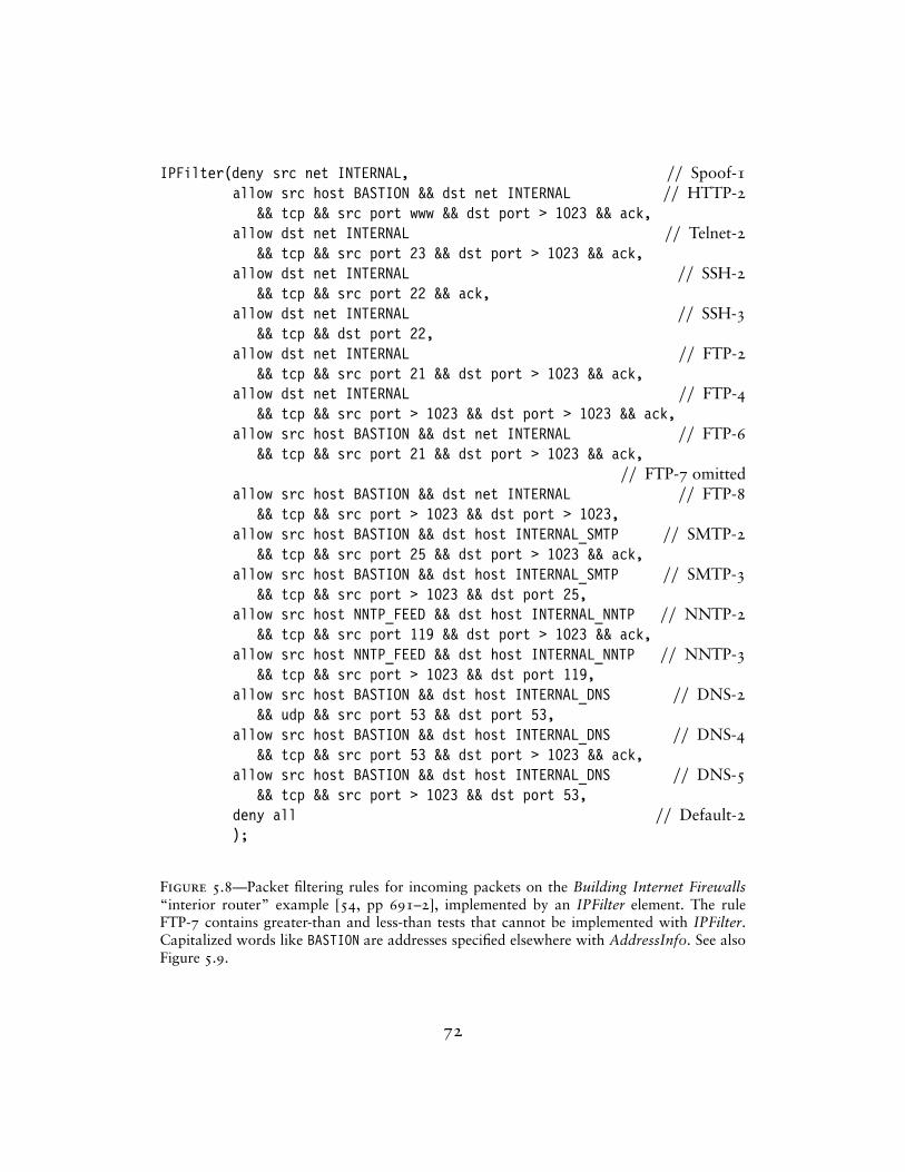
IPFilter(deny src net INTERNAL, // Spoof-1allow src host BASTION && dst net INTERNAL // HTTP-2
&& tcp && src port www && dst port > 1023 && ack,allow dst net INTERNAL // Telnet-2
&& tcp && src port 23 && dst port > 1023 && ack,allow dst net INTERNAL // SSH-2
&& tcp && src port 22 && ack,allow dst net INTERNAL // SSH-3
&& tcp && dst port 22,allow dst net INTERNAL // FTP-2
&& tcp && src port 21 && dst port > 1023 && ack,allow dst net INTERNAL // FTP-4
&& tcp && src port > 1023 && dst port > 1023 && ack,allow src host BASTION && dst net INTERNAL // FTP-6
&& tcp && src port 21 && dst port > 1023 && ack,// FTP-7 omitted
allow src host BASTION && dst net INTERNAL // FTP-8&& tcp && src port > 1023 && dst port > 1023,
allow src host BASTION && dst host INTERNAL_SMTP // SMTP-2&& tcp && src port 25 && dst port > 1023 && ack,
allow src host BASTION && dst host INTERNAL_SMTP // SMTP-3&& tcp && src port > 1023 && dst port 25,
allow src host NNTP_FEED && dst host INTERNAL_NNTP // NNTP-2&& tcp && src port 119 && dst port > 1023 && ack,
allow src host NNTP_FEED && dst host INTERNAL_NNTP // NNTP-3&& tcp && src port > 1023 && dst port 119,
allow src host BASTION && dst host INTERNAL_DNS // DNS-2&& udp && src port 53 && dst port 53,
allow src host BASTION && dst host INTERNAL_DNS // DNS-4&& tcp && src port 53 && dst port > 1023 && ack,
allow src host BASTION && dst host INTERNAL_DNS // DNS-5&& tcp && src port > 1023 && dst port 53,
deny all // Default-2);
Figure 5.8—Packet filtering rules for incoming packets on the Building Internet Firewalls“interior router” example [54, pp 691–2], implemented by an IPFilter element. The ruleFTP-7 contains greater-than and less-than tests that cannot be implemented with IPFilter.Capitalized words like BASTION are addresses specified elsewhere with AddressInfo. See alsoFigure 5.9.
72
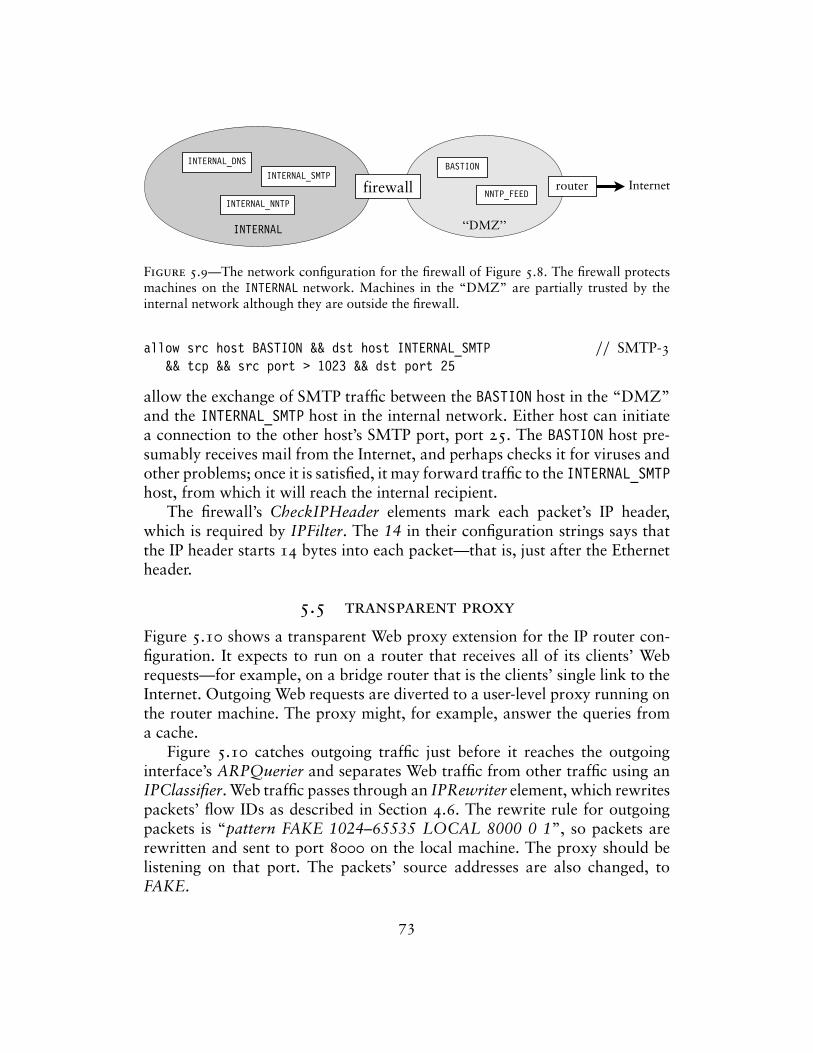
INTERNAL_DNS
INTERNAL_SMTP
INTERNAL_NNTP
INTERNAL
Internetrouterfirewall
BASTION
NNTP_FEED
‘‘DMZ’’
Figure 5.9—The network configuration for the firewall of Figure 5.8. The firewall protectsmachines on the INTERNAL network. Machines in the “DMZ” are partially trusted by theinternal network although they are outside the firewall.
allow src host BASTION && dst host INTERNAL_SMTP // SMTP-3&& tcp && src port > 1023 && dst port 25
allow the exchange of SMTP traffic between the BASTION host in the “DMZ”and the INTERNAL_SMTP host in the internal network. Either host can initiatea connection to the other host’s SMTP port, port 25. The BASTION host pre-sumably receives mail from the Internet, and perhaps checks it for viruses andother problems; once it is satisfied, it may forward traffic to the INTERNAL_SMTPhost, from which it will reach the internal recipient.
The firewall’s CheckIPHeader elements mark each packet’s IP header,which is required by IPFilter. The 14 in their configuration strings says thatthe IP header starts 14 bytes into each packet—that is, just after the Ethernetheader.
5.5 transparent proxy
Figure 5.10 shows a transparent Web proxy extension for the IP router con-figuration. It expects to run on a router that receives all of its clients’ Webrequests—for example, on a bridge router that is the clients’ single link to theInternet. Outgoing Web requests are diverted to a user-level proxy running onthe router machine. The proxy might, for example, answer the queries froma cache.
Figure 5.10 catches outgoing traffic just before it reaches the outgoinginterface’s ARPQuerier and separates Web traffic from other traffic using anIPClassifier. Web traffic passes through an IPRewriter element, which rewritespackets’ flow IDs as described in Section 4.6. The rewrite rule for outgoingpackets is “pattern FAKE 1024–65535 LOCAL 8000 0 1”, so packets arerewritten and sent to port 8000 on the local machine. The proxy should belistening on that port. The packets’ source addresses are also changed, toFAKE.
73
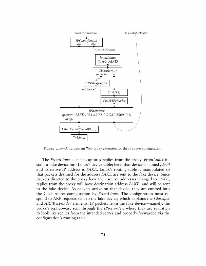
IPClassifier(...)
IPRewriter(pattern FAKE 1024-65535 LOCAL 8000 0 1,
drop)
ToLinux
FromLinux(fdev0, FAKE)
Classifier(...)
ARPResponder
CheckIPHeader
Strip(14)
EtherEncap(0x0800, ...)
Web other
ARP queries IP
to ARPQuerier
from IPFragmenter
to Linux
to LookupIPRoute
Figure 5.10—A transparent Web proxy extension for the IP router configuration.
The FromLinux element captures replies from the proxy. FromLinux in-stalls a fake device into Linux’s device table; here, that device is named fdev0and its native IP address is FAKE. Linux’s routing table is manipulated sothat packets destined for the address FAKE are sent to the fake device. Sincepackets directed to the proxy have their source addresses changed to FAKE,replies from the proxy will have destination address FAKE, and will be sentto the fake device. As packets arrive on that device, they are emitted intothe Click router configuration by FromLinux. The configuration must re-spond to ARP requests sent to the fake device, which explains the Classifierand ARPResponder elements. IP packets from the fake device—namely, theproxy’s replies—are sent through the IPRewriter, where they are rewrittento look like replies from the intended server and properly forwarded via theconfiguration’s routing table.
74
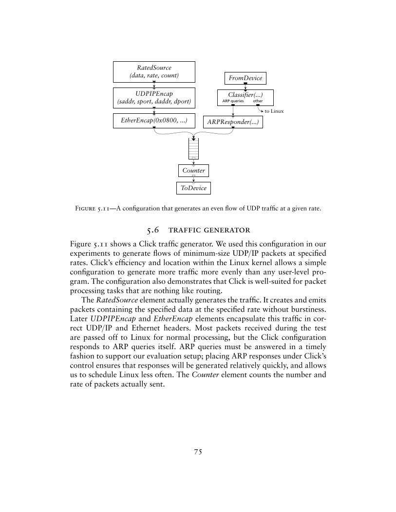
FromDevice
Classifier(...)
ARPResponder(...)
UDPIPEncap(saddr, sport, daddr, dport)
RatedSource(data, rate, count)
EtherEncap(0x0800, ...)
Counter
ToDevice
ARP queries other
to Linux
Figure 5.11—A configuration that generates an even flow of UDP traffic at a given rate.
5.6 traffic generator
Figure 5.11 shows a Click traffic generator. We used this configuration in ourexperiments to generate flows of minimum-size UDP/IP packets at specifiedrates. Click’s efficiency and location within the Linux kernel allows a simpleconfiguration to generate more traffic more evenly than any user-level pro-gram. The configuration also demonstrates that Click is well-suited for packetprocessing tasks that are nothing like routing.
The RatedSource element actually generates the traffic. It creates and emitspackets containing the specified data at the specified rate without burstiness.Later UDPIPEncap and EtherEncap elements encapsulate this traffic in cor-rect UDP/IP and Ethernet headers. Most packets received during the testare passed off to Linux for normal processing, but the Click configurationresponds to ARP queries itself. ARP queries must be answered in a timelyfashion to support our evaluation setup; placing ARP responses under Click’scontrol ensures that responses will be generated relatively quickly, and allowsus to schedule Linux less often. The Counter element counts the number andrate of packets actually sent.
75
6Language tools
This chapter explores the router manipulation tools made possible by Click’sprogramming language. Tools in general can optimize router configurations,transform them, and check whether they satisfy simple properties. We discuss,in particular, a tool for transforming a configuration based on user-specifiedpatterns; two optimization tools that generate specialized C++ source code; atool that eliminates dead code from a configuration; a tool that ensures thatrouters satisfy a global property, namely that packet data is always correctlyaligned; and a tool that combines two or more router definitions into oneconfiguration, enabling global optimizations and analyses on a collection ofrouters. We built these tools to make routers faster—for many of them, wereport how much they speed up the Click IP router in Figure 5.1—and toallow Click to run on non-x86 machines. More fundamentally, though, theydemonstrate how powerful programming language techniques can be whenapplied at the level of system components.
Again, the tools depend on several important properties of the language.First, every router configuration can be expressed in the language, so a lan-guage file is effectively equivalent to a router configuration. Furthermore,because the language is wholly declarative, a configuration can be consid-ered apart from its eventual execution environment. Without this property,it would be difficult to manipulate router descriptions outside of a runningrouter.
Each tool reads a configuration, analyzes and manipulates that configu-ration, reports errors, and writes out the (possibly modified) configuration.Being a language file, the output of one tool is suitable as input for another,so tools can be composed in any order. We categorize the tools according tothree properties:
1. Language-only or language plus source code? Some tools work entirely atthe configuration language level, while others additionally generate C++
76
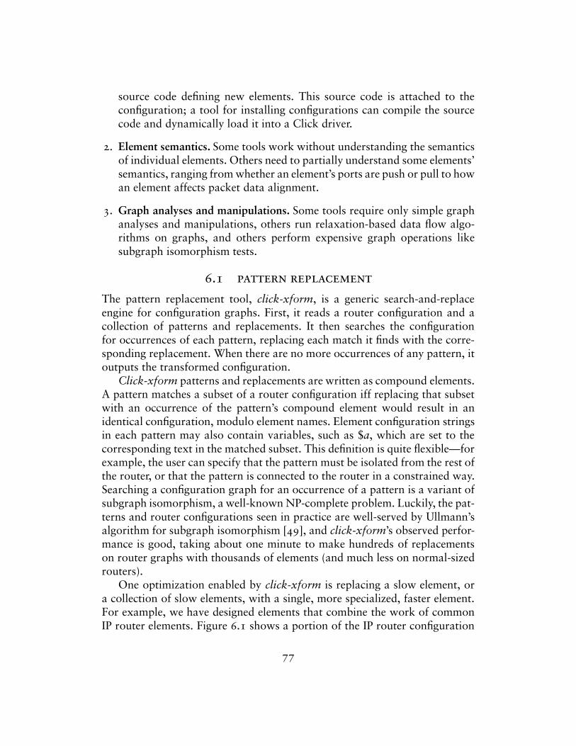
source code defining new elements. This source code is attached to theconfiguration; a tool for installing configurations can compile the sourcecode and dynamically load it into a Click driver.
2. Element semantics. Some tools work without understanding the semanticsof individual elements. Others need to partially understand some elements’semantics, ranging from whether an element’s ports are push or pull to howan element affects packet data alignment.
3. Graph analyses and manipulations. Some tools require only simple graphanalyses and manipulations, others run relaxation-based data flow algo-rithms on graphs, and others perform expensive graph operations likesubgraph isomorphism tests.
6.1 pattern replacement
The pattern replacement tool, click-xform, is a generic search-and-replaceengine for configuration graphs. First, it reads a router configuration and acollection of patterns and replacements. It then searches the configurationfor occurrences of each pattern, replacing each match it finds with the corre-sponding replacement. When there are no more occurrences of any pattern, itoutputs the transformed configuration.
Click-xform patterns and replacements are written as compound elements.A pattern matches a subset of a router configuration iff replacing that subsetwith an occurrence of the pattern’s compound element would result in anidentical configuration, modulo element names. Element configuration stringsin each pattern may also contain variables, such as $a, which are set to thecorresponding text in the matched subset. This definition is quite flexible—forexample, the user can specify that the pattern must be isolated from the rest ofthe router, or that the pattern is connected to the router in a constrained way.Searching a configuration graph for an occurrence of a pattern is a variant ofsubgraph isomorphism, a well-known NP-complete problem. Luckily, the pat-terns and router configurations seen in practice are well-served by Ullmann’salgorithm for subgraph isomorphism [49], and click-xform’s observed perfor-mance is good, taking about one minute to make hundreds of replacementson router graphs with thousands of elements (and much less on normal-sizedrouters).
One optimization enabled by click-xform is replacing a slow element, ora collection of slow elements, with a single, more specialized, faster element.For example, we have designed elements that combine the work of commonIP router elements. Figure 6.1 shows a portion of the IP router configuration
77
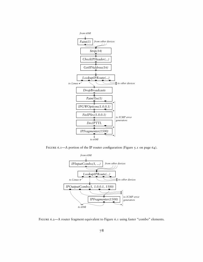
Paint(1)
CheckIPHeader(...)
Strip(14)
GetIPAddress(16)
LookupIPRoute(...)
IPGWOptions(1.0.0.1)
DropBroadcasts
PaintTee(1)
FixIPSrc(1.0.0.1)
DecIPTTL
IPFragmenter(1500)
from eth0
to eth0
from other devices
to Linux to other devices
to ICMP errorgenerators
Figure 6.1—A portion of the IP router configuration (Figure 5.1 on page 64).
IPInputCombo(1, ...)
LookupIPRoute(...)
IPOutputCombo(1, 1.0.0.1, 1500)
IPFragmenter(1500)
from eth0
from other devices
to Linux to other devices
to ICMP errorgenerators
to eth0
Figure 6.2—A router fragment equivalent to Figure 6.1 using faster “combo” elements.
78
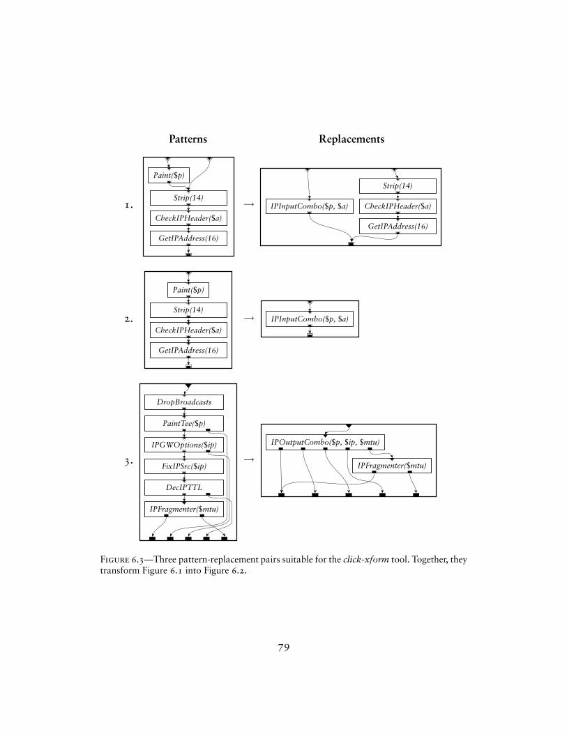
Patterns Replacements
1.
Paint($p)
CheckIPHeader($a)
Strip(14)
GetIPAddress(16)
→ IPInputCombo($p, $a) CheckIPHeader($a)
Strip(14)
GetIPAddress(16)
2.
Paint($p)
CheckIPHeader($a)
Strip(14)
GetIPAddress(16)
→ IPInputCombo($p, $a)
3.
IPFragmenter($mtu)
DropBroadcasts
PaintTee($p)
IPGWOptions($ip)
FixIPSrc($ip)
DecIPTTL
→IPOutputCombo($p, $ip, $mtu)
IPFragmenter($mtu)
Figure 6.3—Three pattern-replacement pairs suitable for the click-xform tool. Together, theytransform Figure 6.1 into Figure 6.2.
79
(Figure 5.1 on page 64) corresponding to one network interface. The frag-ment in Figure 6.2 behaves equivalently, but uses the combination elements.This combination-element configuration takes 29% less CPU time to processa single packet than the original. With the simple pattern set shown in Fig-ure 6.3, click-xform can automatically transform the original fragment intothe combination-element version.
Every element class mentioned in a replacement must already exist. Clickusers, for example, wrote the combination element classes in Figure 6.2 byhand. Click-xform simply changed configurations to use the combination el-ements wherever possible. A single set of patterns can apply to an infinitenumber of configurations, freeing the user from having to update all routersby hand. Furthermore, click-xform lets users work with the original, moremodular configurations, which tend to be more flexible and easier to under-stand, without sacrificing the performance of the specialized versions. Theseare the conventional arguments for any optimizer: a high-level language plusoptimizations is often preferable to a low-level language. In Click, however,programs in the high-level and low-level languages are distinguished not bytheir syntax, but by the element classes they use, and the user can mix high-and low-level languages at will.
Click-xform is also suitable for general-purpose transformations. It could,for example, insert extensions into existing configurations. Well-written pat-terns could upgrade configurations to use new elements or fix bugs.
Click-xform works entirely at the language level and without any knowl-edge of element semantics. Semantic knowledge is encoded in the patternsand replacements, but these are written by users. It performs extensive, andexpensive, graph analysis and manipulation.
Pattern replacement has been implemented in several systems—for exam-ple, Scout [36] has a rule-based global optimizer, and instruction selectors likeBURG [19] attack similar problems for tree structures. Click-xform’s patternlanguage is more powerful than any of these.
6.2 fast classifiers
The fast classifier tool, click-fastclassifier, optimizes configurations that con-tain Classifier, IPClassifier, and IPFilter elements. As described in Section 4.2,these elements traverse a decision tree whose intermediate nodes check packetdata against fixed values, and whose leaves represent particular output ports.Click-fastclassifier makes each such element faster by compiling its decisiontree into C++ code, inlining constants and making branches explicit. DifferentClassifiers are compiled into different C++ classes.
80
Click-fastclassifier also combines adjacent Classifier elements when possi-ble, creating a single fast classifier that does the work of both. This reduces thenumber of elements a packet must travel through, and is particularly useful inthe presence of compound elements, where a user may create adjacent Classi-fiers without realizing it by connecting two compound elements together.
For example, the generated code for Classifier(12/0800, –), a particularlysimple classifier, contains the following function:
inline voidFastClassifier_a_ac::length_unchecked_push(Packet *p){
const unsigned *data = (const unsigned *)(p->data() - 0);step_0:if ((data[3] & 65535U) == 8U) {
output(0).push(p);return;
}output(1).push(p);return;
}
The corresponding function in an unmodified Classifier contains a loop andmany operations involving the decision tree structure:
voidClassifier::push(int, Packet *p){
const unsigned char *packet_data = p->data() - _align_offset;Expr *ex = &_exprs[0]; // avoid bounds checkingint pos = 0;// ...do {
if ((*((unsigned *)(packet_data + ex[pos].offset)) & ex[pos].mask.u)== ex[pos].value.u)
pos = ex[pos].yes;else
pos = ex[pos].no;} while (pos > 0);checked_push_output(-pos, p);
}
The click-fastclassifier tool relies on Click itself to produce the decisiontrees. It starts a user-level Click driver, passes it a stripped-down version of
81
the router configuration, and calls Classifier read handlers that output theoptimized decision trees in text form. This avoids a possibly buggy reimple-mentation of Classifier’s configuration string parsing and decision tree opti-mizations.
Click-fastclassifier both changes the configuration program and compilesnew element classes. It depends intimately on the semantics of Classifier, butrequires little graph analysis or manipulation.
Similar optimization strategies have been developed for BPF [4], DPF [17],and other packet filters. The Click language provides a generic context for thisfilter optimization work, showing that it exemplifies a class of optimizations—where a faster element is swapped in for a slower one. For example, a toolthat generated specialized code for some other element class could share muchof click-fastclassifier’s graph manipulation code.
An IP router configuration with fast classifiers takes 3% less CPU timeto process a single packet than the original. The IP router’s Classifier is verysimple; click-fastclassifier is particularly effective on more complex classifiers.For example, consider the complex IPFilter of Figure 5.8 (page 72). This ele-ment takes 388 nanoseconds to process a packet matching rule DNS-5, morethan five times the cost of many of the IP router’s elements (see Table 8.2 onpage 103). Click-fastclassifier speeds this up to 188 nanoseconds per packet.This 200 nanosecond-per-packet improvement is large enough to have impacton end-to-end performance metrics.
6.3 devirtualization
The click-devirtualize tool optimizes configurations by removing virtual func-tion calls from their elements’ source code. Virtual function calls, or dynamicdispatches, are made through a table of function pointers; on a Pentium III,a mispredicted virtual function call takes dozens of cycles. Packet transferbetween elements is implemented in Click with virtual function calls, whichmakes C++ element classes independent of how their elements are used. How-ever, once the router configuration is known, every packet transfer virtualfunction call could conceivably be replaced by the relevant direct function call,since each element’s position in the configuration is known. Click-devirtualizeimplements this optimization.
The tool reads a configuration program, then reads and partially parsesthe C++ source code for each element class used in that configuration. Finally,it generates one new C++ class per element in the configuration. This code isbased on that element’s original code, but direct function calls replace eachvirtual function call for packet transfer. For example, consider an element
82
whose first output port is connected to the first input port of a Counterelement. Then code like this in the element’s normal class definition:
Element *next = output(0).element();// call goes through virtual function tablenext->push(output(0).port(), packet_ptr);
is transformed by click-devirtualize into code like this:
Counter *next = (Counter *)output(0).element();// call is resolved at compile timenext->Counter::push(0, packet_ptr);
Besides removing the virtual function call, click-devirtualize has inlined thenext input port number. That is, the reference to ‘output(0).port()’ has beenchanged to ‘0’. Click-devirtualize inlines other method calls as well, such asthose that return how many inputs or outputs an element has.
While click-devirtualize can generate a new element class for every ele-ment, it usually does not, because even specialized elements can often sharecode. For example, all Discard elements can share code, since Discard throwsaway every packet it receives: there are no virtual function calls to remove.Because of this, two elements can share code if they have the same class—say,Counter—and they are each connected to a single Discard element. (The twoDiscard elements share a C++ implementation, so the Counters’ push virtualfunction calls both resolve to the same function, Discard::push.) Similarly,two elements with the same class, each connected to one of the two Counters,can also share code, and so forth. Two elements cannot share code if any ofthe following properties is true:
1. The elements have different classes.
2. The elements have different numbers of input or output ports.
3. There exists an input or output port number where that port is push onone element, but pull on the other.
4. There exists an input port number where the corresponding ports are bothpull, but the two elements connected to those ports cannot share code.(For example, the port is connected to a Counter on one element, but aStrip on the other.)
5. There exists an output port number where the corresponding ports areboth push, but the two elements connected to those ports cannot sharecode.
83
A simple data flow algorithm based on the above rules calculates the elementsfor which code sharing is allowed. In our IP router configurations, such asFigure 5.1, analogous elements in different interface paths can always sharecode.
Virtual function calls do have some advantages. For example, infrequentlyexecuted paths may not be important enough to devirtualize—the i-cache costof expanded source code may outweigh the performance savings of removingvirtual functions. To address this, the user can tell click-devirtualize not todevirtualize certain elements.
Click-devirtualize can inline function calls as well as devirtualizing them.This can improve performance significantly, but it currently requires somehand intervention.
The devirtualization tool both changes the configuration program andcompiles new element classes. It depends only on the push/pull propertiesof each element, not on more complex semantic properties; although it re-quires that every element’s source code be available, it does not analyze orunderstand that source code in depth. It requires configuration graph analy-sis, both to discover the push/pull properties of the graph and to determinewhether elements can share code. Both analyses use relatively simple data flowalgorithms. It does not require substantial graph manipulation.
Devirtualization is a well-known technique in object-oriented program-ming languages such as Java. Mosberger et al. [31] demonstrate that pathinlining, essentially devirtualization with inlining, is useful for decreasing pro-tocol latency in a modular networking system (the x-kernel [22]), but theyimplement it by hand. To our knowledge, neither the x-kernel nor Scout [36]can implement devirtualization automatically.5
A devirtualized IP router configuration takes 23% less CPU time to processa single packet than the original.
6.4 dead code elimination
The click-undead tool removes dead code from a router configuration. Deadcode, such as unused or useless elements, rarely occurs in configurationswritten entirely by hand. Configurations containing compound elements willsometimes contain dead code, however, as the user will tend to connect un-needed compound element inputs and outputs to Discard or Idle elements.This might, for example, connect one of a Tee’s branches to an Idle. This
5. Scout paths are automatically “specialized”, but this optimization largely consists ofremoving unneeded queues. Click avoids unneeded queues a priori.
84
branch obviously serves no purpose except to slow down the configuration:it is dead code.
Click-undead first removes all Null, StaticSwitch, and StaticPullSwitchelements from the configuration. Null never occurs in real configurations, butStaticSwitch and StaticPullSwitch are useful for creating conditional branchesin compound elements, as described in Section 3.4. Click-undead redirectsconnections around StaticSwitch, sending packets to the specified output portdirectly. This eliminates one packet transfer on the corresponding path andmay create opportunities for further optimization.
Click-undead next decides which elements are live. An element is live ifit is reachable from both a packet source element and a packet sink ele-ment. Sources and sinks are explicitly marked as such by element designers;sources include InfiniteSource, FromDevice, and FromDump, while sinks in-clude TimedSink, ToDevice, and Discard (when used as a pull element). Dis-covering liveness requires a simple data flow analysis to spread reachabilitydownstream from sources and upstream from sinks. When this is complete,any dead elements are removed. Elements can be explicitly marked as live.Information elements, for example, are always live, so they are not removedeven though they are never reachable.
Next, the tool removes unused ports on scheduler elements and tees. Thissaves the time that would be spent copying a packet only to throw it away,or checking upstream for a packet that could never exist. A port is consideredunused if everything connected to it was dead. Click-undead also removesredundant scheduler elements and tees—that is, schedulers or tees with onlyone input and one output.
Dead code elimination works entirely at the language level. It does re-quire some knowledge of element semantics—namely, source, sink, and live-ness information for some elements, and more detailed knowledge about theswitches, schedulers, and tees specifically mentioned above. It relies on rela-tively simple data flow analysis and graph manipulations.
None of the configurations described in this thesis contain dead code, so wedo not measure click-undead’s effect on performance. Click-undead becomesuseful only for configurations with large numbers of compound elements.
6.5 packet data alignment
The data contained in a Click packet is stored in a flat array of bytes. However,many elements require that data to be aligned on a word boundary. Forexample, elements such as CheckIPHeader expect the IP header to be word-aligned. Other elements, such as Classifier, can adapt to any single alignment,
85
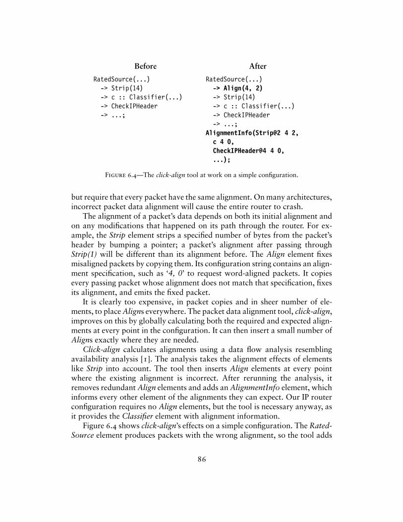
Before
RatedSource(...)-> Strip(14)-> c :: Classifier(...)-> CheckIPHeader-> ...;
After
RatedSource(...)-> Align(4, 2)-> Strip(14)-> c :: Classifier(...)-> CheckIPHeader-> ...;
AlignmentInfo(Strip@2 4 2,c 4 0,CheckIPHeader@4 4 0,...);
Figure 6.4—The click-align tool at work on a simple configuration.
but require that every packet have the same alignment. On many architectures,incorrect packet data alignment will cause the entire router to crash.
The alignment of a packet’s data depends on both its initial alignment andon any modifications that happened on its path through the router. For ex-ample, the Strip element strips a specified number of bytes from the packet’sheader by bumping a pointer; a packet’s alignment after passing throughStrip(1) will be different than its alignment before. The Align element fixesmisaligned packets by copying them. Its configuration string contains an align-ment specification, such as ‘4, 0’ to request word-aligned packets. It copiesevery passing packet whose alignment does not match that specification, fixesits alignment, and emits the fixed packet.
It is clearly too expensive, in packet copies and in sheer number of ele-ments, to place Aligns everywhere. The packet data alignment tool, click-align,improves on this by globally calculating both the required and expected align-ments at every point in the configuration. It can then insert a small number ofAligns exactly where they are needed.
Click-align calculates alignments using a data flow analysis resemblingavailability analysis [1]. The analysis takes the alignment effects of elementslike Strip into account. The tool then inserts Align elements at every pointwhere the existing alignment is incorrect. After rerunning the analysis, itremoves redundant Align elements and adds an AlignmentInfo element, whichinforms every other element of the alignments they can expect. Our IP routerconfiguration requires no Align elements, but the tool is necessary anyway, asit provides the Classifier element with alignment information.
Figure 6.4 shows click-align’s effects on a simple configuration. The Rated-Source element produces packets with the wrong alignment, so the tool adds
86
a single Align element. The AlignmentInfo element informs the Classifier cthat its received packets will be word-aligned (‘4 0’).
On x86-based machines, the click-align tool is optional—unaligned ac-cesses are legal, and not any slower than aligned accesses. (An unalignedaccess can cause two d-cache misses if it straddles two cache lines, but thisis not a problem in practice, as the packet data is always in the cache.) Onother architectures, however, configurations that have not been checked withclick-align cause Click to crash.
The alignment tool works entirely at the language level and requires knowl-edge of the alignment-related semantics of each element. Its data flow analysesare relatively complex—for example, two different analyses are required todiscover what alignments elements need and what alignments they can expect.However, its graph manipulations are simple. It has no effect on performanceunless you count that on some architectures, unaligned configurations do notwork at all.
6.6 multiple-router configurations
The click-combine tool can combine several router configurations into onelarger configuration that gives a detailed picture of the overall network. Forexample, if the output interface of one router is connected to the input interfaceof another by a point-to-point link, then the combined configuration will haveexplicit connections between the relevant interfaces. This unified Click graphcan be analyzed and manipulated using language techniques like the onesdescribed above, ensuring properties of the network—for instance, that theframe formats at either end of each link are compatible—or removing redun-dant computation performed by more than one router. The click-uncombinetool can then separate the combined configuration into its component routerparts. For example, Figure 6.5 shows part of a combined router generated byclick-combine. Router A’s ToDevice(eth0) was connected by a point-to-pointlink to router B’s PollDevice(eth1).
One optimization enabled by router combination is ARP elimination. Iftwo routers are connected by a point-to-point Ethernet link, there is no needto have a full ARP mechanism in place on that link; each router can bepreprogrammed with the Ethernet address of the other. The ARP elimina-tion optimization removes ARPQuerier and ARPResponder elements froma configuration, replacing them with the corresponding EtherEncap element.Another optimization might remove redundant IPFragmenter elements. Eachlink has a hard-wired maximum transmission length, or MTU; IPFragmenterbreaks packets larger than this length into fragments before sending them.
87
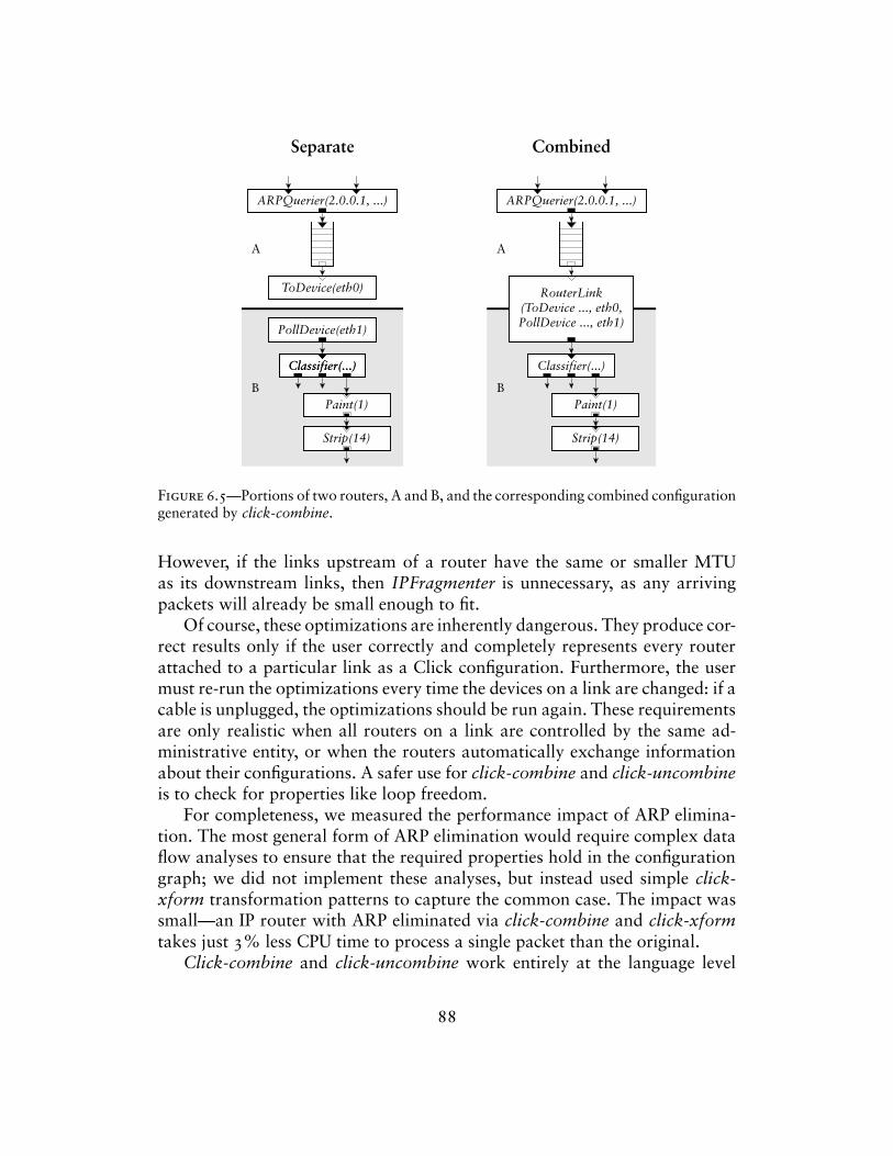
Separate
Classifier(...)
PollDevice(eth1)
Classifier(...)
Paint(1)
Strip(14)
ARPQuerier(2.0.0.1, ...)
ToDevice(eth0)
A
B
Combined
Classifier(...)
Paint(1)
Strip(14)
ARPQuerier(2.0.0.1, ...)
RouterLink(ToDevice ..., eth0,PollDevice ..., eth1)
A
B
Figure 6.5—Portions of two routers, A and B, and the corresponding combined configurationgenerated by click-combine.
However, if the links upstream of a router have the same or smaller MTUas its downstream links, then IPFragmenter is unnecessary, as any arrivingpackets will already be small enough to fit.
Of course, these optimizations are inherently dangerous. They produce cor-rect results only if the user correctly and completely represents every routerattached to a particular link as a Click configuration. Furthermore, the usermust re-run the optimizations every time the devices on a link are changed: if acable is unplugged, the optimizations should be run again. These requirementsare only realistic when all routers on a link are controlled by the same ad-ministrative entity, or when the routers automatically exchange informationabout their configurations. A safer use for click-combine and click-uncombineis to check for properties like loop freedom.
For completeness, we measured the performance impact of ARP elimina-tion. The most general form of ARP elimination would require complex dataflow analyses to ensure that the required properties hold in the configurationgraph; we did not implement these analyses, but instead used simple click-xform transformation patterns to capture the common case. The impact wassmall—an IP router with ARP eliminated via click-combine and click-xformtakes just 3% less CPU time to process a single packet than the original.
Click-combine and click-uncombine work entirely at the language level
88
and do not need to understand element semantics. Their graph manipulationsand analyses are extensive, but simple. Individual multiple-router optimiza-tions like ARP elimination resemble some kinds of programming languageoptimizations, such as interprocedural optimizations.
6.7 discussion
The partial information that some language tools need about element classesis often quite simple. For example, several tools only need to know whetherports are push or pull. Extracting this information from the C++ implemen-tation would be a difficult, if not impossible, task. Instead, we supply severalparallel definitions for each element class. For example, each element has aC++ definition and a push/pull definition; some elements have additional def-initions as required by the tools. In this approach, the user creates simple,high-level specifications for each element and each property required. Thesespecifications are focused and easy to write, and they facilitate incrementalspecification—the behavior of an element is specified as tools are built. How-ever, they force the user to write many specifications for each element, and asnew tools become available, old element classes may need to be updated withnew specification information. Furthermore, the additional specifications arenot required by the drivers, so element designers may tend to put off writingthem.
One could instead write element implementations in a language that facili-tated analysis, then extract all necessary information from those implementa-tions. For example, in the Ensemble system for composing network protocolstacks [25], components are written in Objective Caml. However, despite itsrelative convenience for analysis, Objective Caml is still so general that acomplex theorem prover and extensive human intervention are required toanalyze Ensemble components. Click’s design avoids these costs.
Tools are relatively simple to write, but certainly not as simple as ele-ments. A tool library has functions for reading configurations, flattening themto remove compound elements, searching configuration graphs for specificelements or connection patterns, and so forth. Writing a tool is nontrivialdespite this. After all, the Click language is still a programming language,however simple, and tools have some similarities to compiler passes. Ma-nipulating any program is a difficult task because of the exhaustive analysisrequired to handle all cases, and the compiler knowledge required to design atool is significantly greater than the system knowledge required to design anelement. A higher-level library that made it easier to develop new tools wouldbe useful.
89
7Implementation
This chapter describes how the Click kernel driver was implemented, includingthe changes to Linux required to achieve good performance.
The Click kernel driver runs as a kernel thread under Linux 2.2. Thekernel thread loops over the current router’s task queue and runs each task.Only interrupts can preempt this thread, but to keep the system responsive, itvoluntarily gives up the CPU to Linux from time to time; the user can specifyhow often with a ScheduleLinux information element. There is generally onlyone Click thread active at a time. However, during configuration installation,there may be two or more simultaneously active router configurations anddriver threads—the new router plus several old ones in the process of dying.
The Click kernel driver uses Linux’s /proc filesystem to communicatewith user processes. To bring a router on line, the user creates a configura-tion description in the Click language and writes it to /proc/click/config (or/proc/click/hotconfig for a hot-swap installation). Other files in the /proc/click directory export information about the current configuration, a list ofelement classes known to the driver, and so on. When installing a router con-figuration, Click creates a subdirectory under /proc/click for each element.This subdirectory contains that element’s handlers (Section 2.8). The code thathandles accesses to /proc runs outside the Click thread in the context of thereading or writing process.
Besides packets, important objects in a running Click router include:
– Elements. The system contains an element object for each element in thecurrent configuration, as well as prototype objects for every kind of prim-itive element that could be used. Element prototypes can be added to andremoved from the running driver.
– Router. The single router object collects general information relevant toa given router configuration. It configures the elements, checks that con-
90
nections are valid, and puts the router on line; it also manages the taskqueue.
– Timers. In the kernel driver, Click timers are implemented with Linux timerqueues. On Intel PCs, these have .01-second resolution.
7.1 polling and device handling
The original Click system [29] shared Linux’s interrupt structure and devicehandling; our goal was to change Linux as little as possible. However, in-terrupt overhead and device handling dominated that system’s performance,consuming about 4.8 and 6.7 µs respectively of the total of 13 µs required toforward a packet on a 700 MHz Pentium III PC. In addition, Click processedpackets at a lower priority than interrupts, leading to receive livelock [28]: asthe number of input packets increased, interrupt processing eventually starvedall other system tasks, leading to reduced throughput.
Click now eliminates interrupts in favor of polling. A new device-handlingelement, PollDevice, is the polling equivalent of FromDevice; it puts the rel-evant device into polling mode and puts itself on Click’s task queue to waitfor packets. When activated, PollDevice polls its device’s receive DMA queuefor newly arrived packets; if any are found, it pushes them through the con-figuration. ToDevice also places itself on the task queue. When activated, itexamines its device’s transmit DMA queue for empty slots, which it fills bypulling packets from its input. These elements also refill the receive DMA listwith empty buffers and remove transmitted buffers from the transmit DMAlist. The device never interrupts the processor; furthermore, Linux networkingcode never executes except as requested by the Click router configuration.6
Mogul and Ramakrishnan [28] also used polling to eliminate receive livelock.However, their system left interrupts enabled under light load, while Click is apure polling system—even infrequent PC interrupts are simply too expensive.
Polling required changes to Linux’s structure representing network devicesand to the drivers for our network devices. The new device structure includes,for example, methods to turn interrupts on and off, to poll for received pack-ets, and to clean the transmit DMA ring.
6. The FromDevice element still uses interrupts, however. With FromDevice, Click can usedevices whose drivers don’t support polling. On an interrupt, FromDevice stores packets in aninternal ring buffer. Like PollDevice, it places itself on the router’s task queue. It then outputspackets from that ring buffer as it is activated. This avoids race conditions in configurationscontaining both FromDevice and PollDevice, but does make FromDevice-only configurationsslower than they were before. Our test configurations all use PollDevice.
91
The introduction of polling let us eliminate all programmed I/O (PIO)interaction with the Ethernet controllers. One PIO reenabled receive interruptsafter an interrupt was processed, and was not necessary in a polling system.The second PIO was used in the send routine to tell the controller to lookfor a new packet to transmit. To eliminate it, we configured the network cardto periodically check the transmit DMA queue for new packets. As a result,all communication between Click and the controller takes place indirectlythrough the shared DMA queues in main memory, in the style of the Osirisnetwork controller [14]. This saved roughly two microseconds per packet, asa PIO takes about 1 µs to execute.
These improvements eliminated receive livelock, reduced the total timerequired to process a packet from 13 µs to 2.8 µs, and increased Click’s maxi-mum loss-free forwarding rate of minimum-sized packets more than fourfold.Mogul and Ramakrishnan [28] found that polling eliminated receive livelockbut did not increase peak forwarding rate. We hypothesize that interruptsare relatively much more expensive on PCs than on the Alpha hardware theyused.
92
8Evaluation
This chapter evaluates Click’s performance for IP routing and for severalextended configurations. We also describe and analyze sources of overhead inClick’s design and implementation, and demonstrate the practical effectivenessof the language tool optimizations.
Our goal is to understand the performance of a particular Click router,the performance limitations of the Click architecture, and the performancecharacteristics of our PC hardware. We will show that the Click architecture’sonly significant performance limitation is the cost of virtual function calls, andthat the language tool optimizations successfully address this cost. We alsoargue that our PC hardware is limited, by either the PCI bus or the memorysystem, to a sustained forwarding rate of about 400,000 64-byte packets persecond, and show that our optimized IP router configurations easily achievethis rate. Finally, we show that Click can enforce quality-of-service constraintsvery well under ordinary loads, and reasonably well even under overload.
An unoptimized Click IP router achieves a maximum loss-free forwardingrate of 357,000 64-byte packets per second. With language tool optimizations,this rate rises to 446,000 packets per second. For comparison, a common edgerouter, the Cisco 7200 series, can route 200,000 packets per second. The costof this router is about a factor of ten more than the cost of the hardwarewe used. (Of course, the two routers are not really comparable. Cisco routerhardware is presumably more reliable than PC hardware. Furthermore, theCisco router has functionality not currently available in Click—such as routingprotocol support—although most of this functionality is probably not on theforwarding path.)
8.1 experimental setup
The experimental setup consists of a total of nine Intel PCs running a modifiedversion of Linux 2.2.16. (We patched Linux to add support for Click’s polling
93
device drivers.) Of the nine PCs, one is the router host, four are source hosts,and four are destination hosts. The router host has eight 100 Mbit/s Ethernetcontrollers connected, by point-to-point links, to the source and destinationhosts. During a test, each source generates an even flow of UDP packetsaddressed to a corresponding destination; the router is expected to get themthere.
The router host has a 700 MHz Intel Pentium III CPU and an IntelL440GX+ motherboard. Its eight DEC 21140 Tulip 100 Mbit/s PCI Eth-ernet controllers [13] are on multi-port cards split across the motherboard’stwo independent PCI buses. The Pentium III has a 16 KB level-1 instructioncache, a 16 KB level-1 data cache, and a 256 KB level-2 unified cache. Thesource and destination hosts have 733 MHz Pentium III CPUs and 200 MHzPentium Pro CPUs, respectively. Each host has one DEC 21140 Ethernet con-troller. The source-to-router and router-to-destination links are point-to-pointfull-duplex 100 Mbit/s Ethernet.
The source hosts generate UDP packets at specified rates, and can gen-erate up to 147,900 64-byte packets per second; the destination hosts countand discard the forwarded UDP packets. Each 64-byte UDP packet includesEthernet, IP, and UDP headers as well as 14 bytes of data and the 4-byte Eth-ernet CRC. When the 64-bit preamble and 96-bit inter-frame gap are added,a 100 Mbit/s Ethernet link can carry up to 148,800 such packets per second.
This setup is easier on routers than a real network might be. The tests didnot involve fragmentation, IP options, or ICMP errors, though Figure 5.1 hasall the code needed to handle these. More destination hosts might slow Clickdown by increasing the number of ARP table entries. A larger routing tablemight also slow down Click’s simple routing table implementation; previouswork on fast lookup in large tables has addressed this problem [12, 51]. Thesetup is nevertheless sufficient to analyze the architectural aspects of Click’sperformance.
Click’s modularity is as convenient for measuring performance as it isfor building routers. Our source hosts generate packets using the Click con-figuration described in Section 5.6; the destination hosts use another Clickconfiguration to receive them. Particular measurements made use of Click el-ements that check Pentium III cycle counters and performance counters, andthat poll Tulip network interface status. All of these elements are distributedwith the Click software.
94
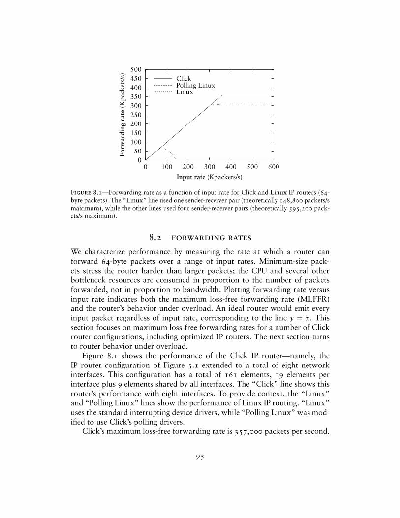
050
100150200250300350400450500
0 100 200 300 400 500 600
Forw
ardi
ng r
ate
(Kpa
cket
s/s)
Input rate (Kpackets/s)
ClickPolling LinuxLinux
Figure 8.1—Forwarding rate as a function of input rate for Click and Linux IP routers (64-byte packets). The “Linux” line used one sender-receiver pair (theoretically 148,800 packets/smaximum), while the other lines used four sender-receiver pairs (theoretically 595,200 pack-ets/s maximum).
8.2 forwarding rates
We characterize performance by measuring the rate at which a router canforward 64-byte packets over a range of input rates. Minimum-size pack-ets stress the router harder than larger packets; the CPU and several otherbottleneck resources are consumed in proportion to the number of packetsforwarded, not in proportion to bandwidth. Plotting forwarding rate versusinput rate indicates both the maximum loss-free forwarding rate (MLFFR)and the router’s behavior under overload. An ideal router would emit everyinput packet regardless of input rate, corresponding to the line y = x. Thissection focuses on maximum loss-free forwarding rates for a number of Clickrouter configurations, including optimized IP routers. The next section turnsto router behavior under overload.
Figure 8.1 shows the performance of the Click IP router—namely, theIP router configuration of Figure 5.1 extended to a total of eight networkinterfaces. This configuration has a total of 161 elements, 19 elements perinterface plus 9 elements shared by all interfaces. The “Click” line shows thisrouter’s performance with eight interfaces. To provide context, the “Linux”and “Polling Linux” lines show the performance of Linux IP routing. “Linux”uses the standard interrupting device drivers, while “Polling Linux” was mod-ified to use Click’s polling drivers.
Click’s maximum loss-free forwarding rate is 357,000 packets per second.
95
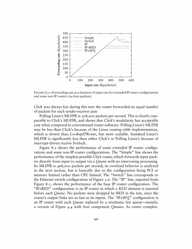
050
100150200250300350400450500
0 100 200 300 400 500 600
Forw
ardi
ng r
ate
(Kpa
cket
s/s)
Input rate (Kpackets/s)
SimpleSwitchIPIP+REDIP+SFQ
Figure 8.2—Forwarding rate as a function of input rate for extended IP router configurationsand some non-IP routers (64-byte packets).
Click was always fair during this test: the router forwarded an equal numberof packets for each sender-receiver pair.
Polling Linux’s MLFFR is 308,000 packets per second. This is clearly com-parable to Click’s MLFFR, and shows that Click’s modularity has acceptablecost when compared to conventional router software. Polling Linux’s MLFFRmay be less than Click’s because of the Linux routing table implementation,which is slower than LookupIPRoute, but more scalable. Standard Linux’sMLFFR is significantly less than either Click’s or Polling Linux’s because ofinterrupt-driven receive livelock.
Figure 8.2 shows the performance of some extended IP router configu-rations and some non-IP-router configurations. The “Simple” line shows theperformance of the simplest possible Click router, which forwards input pack-ets directly from input to output via a Queue with no intervening processing.Its MLFFR is 468,000 packets per second; its overload behavior is analyzedin the next section, but is basically due to the configuration being PCI ormemory limited rather than CPU limited. The “Switch” line corresponds tothe Ethernet switch configuration of Figure 5.6. The “IP” line, repeated fromFigure 8.1, shows the performance of the base IP router configuration. The“IP+RED” configuration is an IP router in which a RED element is insertedbefore each Queue. No packets were dropped by RED in the test, since therouter’s output links are as fast as its inputs. The “IP+SFQ” configuration isan IP router with each Queue replaced by a stochastic fair queue—namely,a version of Figure 4.4 with four component Queues. As router complex-
96
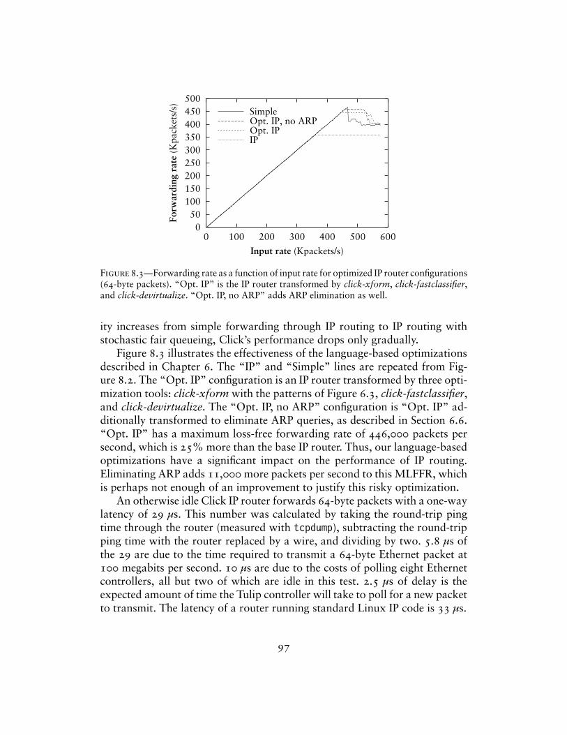
050
100150200250300350400450500
0 100 200 300 400 500 600
Forw
ardi
ng r
ate
(Kpa
cket
s/s)
Input rate (Kpackets/s)
SimpleOpt. IP, no ARPOpt. IPIP
Figure 8.3—Forwarding rate as a function of input rate for optimized IP router configurations(64-byte packets). “Opt. IP” is the IP router transformed by click-xform, click-fastclassifier,and click-devirtualize. “Opt. IP, no ARP” adds ARP elimination as well.
ity increases from simple forwarding through IP routing to IP routing withstochastic fair queueing, Click’s performance drops only gradually.
Figure 8.3 illustrates the effectiveness of the language-based optimizationsdescribed in Chapter 6. The “IP” and “Simple” lines are repeated from Fig-ure 8.2. The “Opt. IP” configuration is an IP router transformed by three opti-mization tools: click-xform with the patterns of Figure 6.3, click-fastclassifier,and click-devirtualize. The “Opt. IP, no ARP” configuration is “Opt. IP” ad-ditionally transformed to eliminate ARP queries, as described in Section 6.6.“Opt. IP” has a maximum loss-free forwarding rate of 446,000 packets persecond, which is 25% more than the base IP router. Thus, our language-basedoptimizations have a significant impact on the performance of IP routing.Eliminating ARP adds 11,000 more packets per second to this MLFFR, whichis perhaps not enough of an improvement to justify this risky optimization.
An otherwise idle Click IP router forwards 64-byte packets with a one-waylatency of 29 µs. This number was calculated by taking the round-trip pingtime through the router (measured with tcpdump), subtracting the round-tripping time with the router replaced by a wire, and dividing by two. 5.8 µs ofthe 29 are due to the time required to transmit a 64-byte Ethernet packet at100 megabits per second. 10 µs are due to the costs of polling eight Ethernetcontrollers, all but two of which are idle in this test. 2.5 µs of delay is theexpected amount of time the Tulip controller will take to poll for a new packetto transmit. The latency of a router running standard Linux IP code is 33 µs.
97
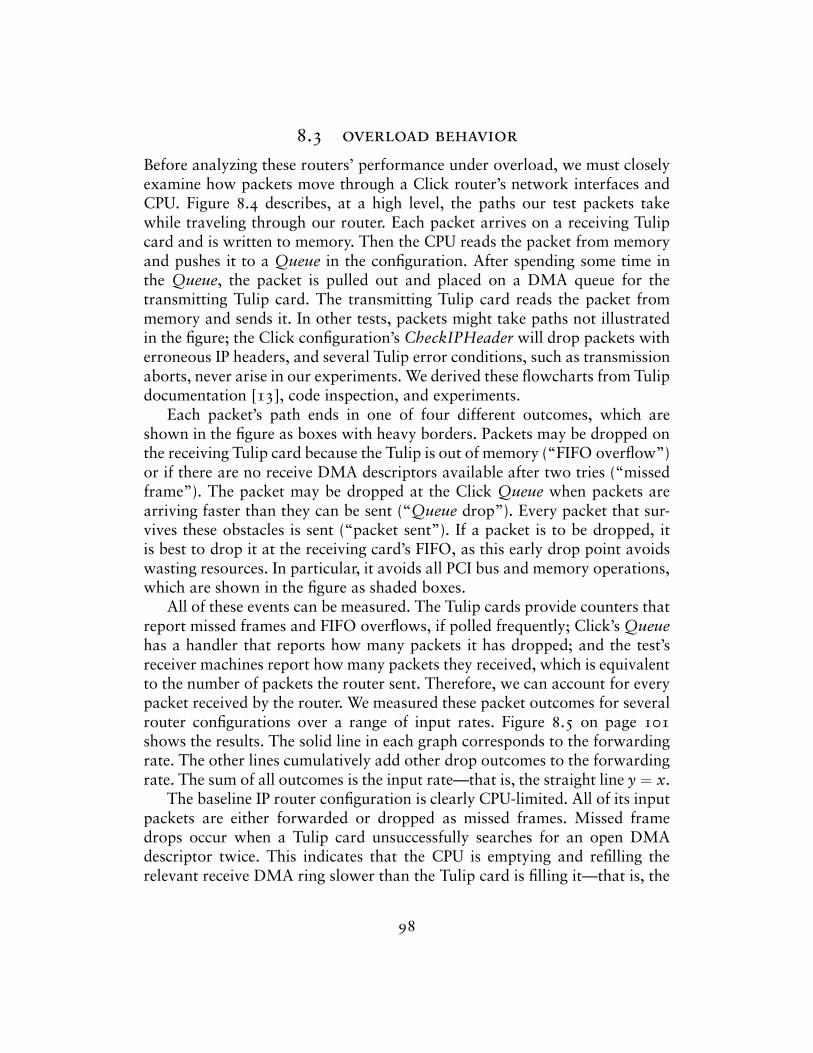
8.3 overload behavior
Before analyzing these routers’ performance under overload, we must closelyexamine how packets move through a Click router’s network interfaces andCPU. Figure 8.4 describes, at a high level, the paths our test packets takewhile traveling through our router. Each packet arrives on a receiving Tulipcard and is written to memory. Then the CPU reads the packet from memoryand pushes it to a Queue in the configuration. After spending some time inthe Queue, the packet is pulled out and placed on a DMA queue for thetransmitting Tulip card. The transmitting Tulip card reads the packet frommemory and sends it. In other tests, packets might take paths not illustratedin the figure; the Click configuration’s CheckIPHeader will drop packets witherroneous IP headers, and several Tulip error conditions, such as transmissionaborts, never arise in our experiments. We derived these flowcharts from Tulipdocumentation [13], code inspection, and experiments.
Each packet’s path ends in one of four different outcomes, which areshown in the figure as boxes with heavy borders. Packets may be dropped onthe receiving Tulip card because the Tulip is out of memory (“FIFO overflow”)or if there are no receive DMA descriptors available after two tries (“missedframe”). The packet may be dropped at the Click Queue when packets arearriving faster than they can be sent (“Queue drop”). Every packet that sur-vives these obstacles is sent (“packet sent”). If a packet is to be dropped, itis best to drop it at the receiving card’s FIFO, as this early drop point avoidswasting resources. In particular, it avoids all PCI bus and memory operations,which are shown in the figure as shaded boxes.
All of these events can be measured. The Tulip cards provide counters thatreport missed frames and FIFO overflows, if polled frequently; Click’s Queuehas a handler that reports how many packets it has dropped; and the test’sreceiver machines report how many packets they received, which is equivalentto the number of packets the router sent. Therefore, we can account for everypacket received by the router. We measured these packet outcomes for severalrouter configurations over a range of input rates. Figure 8.5 on page 101shows the results. The solid line in each graph corresponds to the forwardingrate. The other lines cumulatively add other drop outcomes to the forwardingrate. The sum of all outcomes is the input rate—that is, the straight line y = x.
The baseline IP router configuration is clearly CPU-limited. All of its inputpackets are either forwarded or dropped as missed frames. Missed framedrops occur when a Tulip card unsuccessfully searches for an open DMAdescriptor twice. This indicates that the CPU is emptying and refilling therelevant receive DMA ring slower than the Tulip card is filling it—that is, the
98
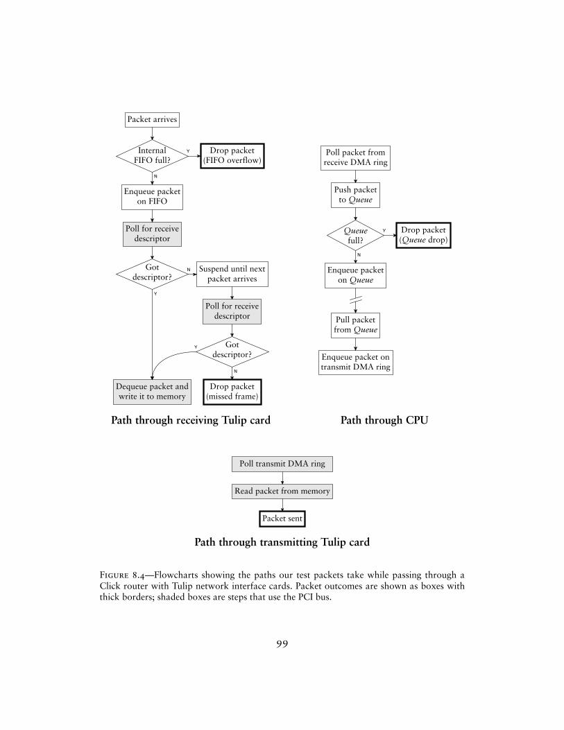
Packet arrives
InternalFIFO full?
Enqueue packeton FIFO
Poll for receivedescriptor
Gotdescriptor?
Suspend until nextpacket arrives
Poll for receivedescriptor
Gotdescriptor?
Drop packet(FIFO overflow)
Drop packet(missed frame)
Dequeue packet andwrite it to memory
N
Y
Y
N
Y
N
Poll packet fromreceive DMA ring
Queuefull?
Pull packetfrom Queue
Push packetto Queue
Enqueue packeton Queue
Enqueue packet ontransmit DMA ring
Drop packet(Queue drop)
N
Y
Path through receiving Tulip card Path through CPU
Read packet from memory
Poll transmit DMA ring
Packet sent
Path through transmitting Tulip card
Figure 8.4—Flowcharts showing the paths our test packets take while passing through aClick router with Tulip network interface cards. Packet outcomes are shown as boxes withthick borders; shaded boxes are steps that use the PCI bus.
99
CPU is overloaded, so the relevant PollDevice is running infrequently.The “Simple” configuration is not CPU-limited. None of the packets
dropped by “Simple” are missed frames; they are either FIFO overflows orQueue drops. Both of these outcomes indicate that the PCI bus or mem-ory system is overloaded. FIFO overflows occur when a receiving Tulip cardgets packets faster than it can request DMA descriptors and write packetsto memory. Queue drops occur when packets are added to a Queue fasterthan ToDevice removes them. Instrumenting the ToDevices revealed that theywere often idle—that is, they chose not to pull packets—because their devices’transmit DMA queues were full. Thus, the CPU wanted to send packets fasterthan the transmitting Tulip cards could process them. These possible bottle-neck tasks—reading packets from memory, writing packets to memory, andrequesting DMA descriptors—are limited not by the CPU, but by the PCI busor the memory system. Our analysis is not detailed enough to determine thebottleneck resource precisely. Other researchers have suggested in personalcommunication that the memory system is a likely candidate—in particular,that validating data received from the PCI bus against the CPU’s caches is anexpensive operation.
The “Simple” forwarding rate drops when Queues begin dropping packets.This happens soon after the ToDevice elements begin noticing full transmitDMA queues. The forwarding rate may drop, rather than holding steady,because each packet dropped at a Queue has already consumed some criticalresources—namely, the PCI or memory bandwidth required to fetch a receivedescriptor, write the packet into memory, and read it from memory into theCPU’s cache. Thus, dropping the packet at a Queue is worse than neverreceiving the packet at all. This waste causes livelock. The forwarding rateflattens out again when packets begin dropping due to FIFO overflows. Thesepackets have consumed no critical resources, so they don’t cause livelock.
The “Optimized IP, no ARP” configuration is CPU-limited over a rangeof input rates, but then becomes PCI- or memory-limited. At input rates upto 500,000 packets per second, all dropped packets are due to missed frames,indicating that the CPU is the bottleneck. The forwarding rate is flat for atime, but then begins to drop. Again, this may be due to livelock—whilemissed frames are not as wasteful as Queue drops, they do exhaust some PCIbandwidth by requesting useless receive descriptors. At 500,000 packets persecond, however, FIFO overflows start to occur. This indicates that the CPUis no longer the bottleneck. The Tulip card’s FIFO is filling up, so it must bereceiving a decent number of receive descriptors; otherwise, the FIFO wouldempty due to missed frames. Once the Tulip’s FIFO is full, the forwarding rateflattens out, again to around 400,000 packets per second. All four fast router
100
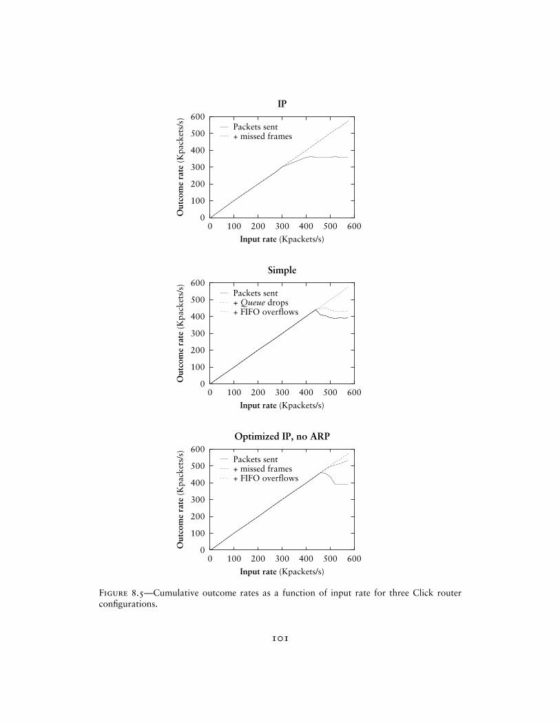
0
100
200
300
400
500
600
0 100 200 300 400 500 600
Out
com
e ra
te (
Kpa
cket
s/s)
Input rate (Kpackets/s)
IP
Packets sent+ missed frames
0
100
200
300
400
500
600
0 100 200 300 400 500 600
Out
com
e ra
te (
Kpa
cket
s/s)
Input rate (Kpackets/s)
Simple
Packets sent+ Queue drops+ FIFO overflows
0
100
200
300
400
500
600
0 100 200 300 400 500 600
Out
com
e ra
te (
Kpa
cket
s/s)
Input rate (Kpackets/s)
Optimized IP, no ARP
Packets sent+ missed frames+ FIFO overflows
Figure 8.5—Cumulative outcome rates as a function of input rate for three Click routerconfigurations.
101
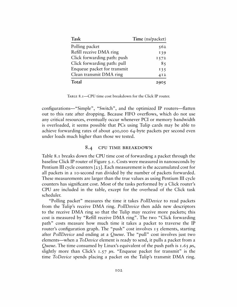
Task Time (ns/packet)
Polling packet 562Refill receive DMA ring 139Click forwarding path: push 1572Click forwarding path: pull 85Enqueue packet for transmit 135Clean transmit DMA ring 412
Total 2905
Table 8.1—CPU time cost breakdown for the Click IP router.
configurations—“Simple”, “Switch”, and the optimized IP routers—flattenout to this rate after dropping. Because FIFO overflows, which do not useany critical resources, eventually occur whenever PCI or memory bandwidthis overloaded, it seems possible that PCs using Tulip cards may be able toachieve forwarding rates of about 400,000 64-byte packets per second evenunder loads much higher than those we tested.
8.4 cpu time breakdown
Table 8.1 breaks down the CPU time cost of forwarding a packet through thebaseline Click IP router of Figure 5.1. Costs were measured in nanoseconds byPentium III cycle counters [23]. Each measurement is the accumulated cost forall packets in a 10-second run divided by the number of packets forwarded.These measurements are larger than the true values as using Pentium III cyclecounters has significant cost. Most of the tasks performed by a Click router’sCPU are included in the table, except for the overhead of the Click taskscheduler.
“Polling packet” measures the time it takes PollDevice to read packetsfrom the Tulip’s receive DMA ring. PollDevice then adds new descriptorsto the receive DMA ring so that the Tulip may receive more packets; thiscost is measured by “Refill receive DMA ring”. The two “Click forwardingpath” costs measure how much time it takes a packet to traverse the IProuter’s configuration graph. The “push” cost involves 15 elements, startingafter PollDevice and ending at a Queue. The “pull” cost involves just twoelements—when a ToDevice element is ready to send, it pulls a packet from aQueue. The time consumed by Linux’s equivalent of the push path is 1.65 µs,slightly more than Click’s 1.57 µs. “Enqueue packet for transmit” is thetime ToDevice spends placing a packet on the Tulip’s transmit DMA ring.
102
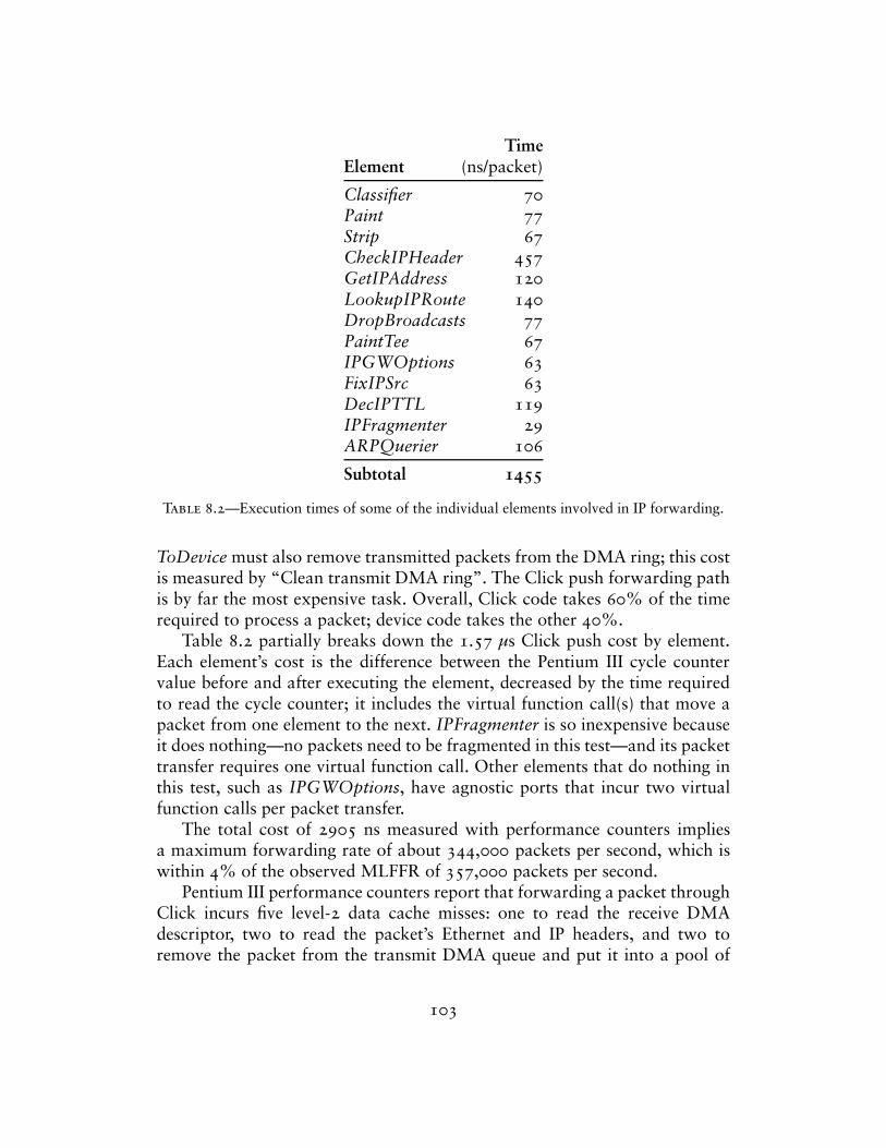
TimeElement (ns/packet)
Classifier 70Paint 77Strip 67CheckIPHeader 457GetIPAddress 120LookupIPRoute 140DropBroadcasts 77PaintTee 67IPGWOptions 63FixIPSrc 63DecIPTTL 119IPFragmenter 29ARPQuerier 106
Subtotal 1455
Table 8.2—Execution times of some of the individual elements involved in IP forwarding.
ToDevice must also remove transmitted packets from the DMA ring; this costis measured by “Clean transmit DMA ring”. The Click push forwarding pathis by far the most expensive task. Overall, Click code takes 60% of the timerequired to process a packet; device code takes the other 40%.
Table 8.2 partially breaks down the 1.57 µs Click push cost by element.Each element’s cost is the difference between the Pentium III cycle countervalue before and after executing the element, decreased by the time requiredto read the cycle counter; it includes the virtual function call(s) that move apacket from one element to the next. IPFragmenter is so inexpensive becauseit does nothing—no packets need to be fragmented in this test—and its packettransfer requires one virtual function call. Other elements that do nothing inthis test, such as IPGWOptions, have agnostic ports that incur two virtualfunction calls per packet transfer.
The total cost of 2905 ns measured with performance counters impliesa maximum forwarding rate of about 344,000 packets per second, which iswithin 4% of the observed MLFFR of 357,000 packets per second.
Pentium III performance counters report that forwarding a packet throughClick incurs five level-2 data cache misses: one to read the receive DMAdescriptor, two to read the packet’s Ethernet and IP headers, and two toremove the packet from the transmit DMA queue and put it into a pool of
103

Time (ns/packet) % of Total % ofConfiguration Push Pull Click IP Time IP
Simple 97 91 187 11% 1715 59%Switch 958 83 1040 63% 2324 80%Optimized IP, no ARP 991 69 1061 64% 2256 78%Optimized IP 1033 68 1101 66% 2414 83%IP + click-xform 1093 81 1174 71% 2480 85%IP + click-devirtualize 1207 67 1274 77% 2532 87%IP + ARP elimination 1516 84 1600 97% 2809 97%IP + click-fastclassifier 1536 75 1611 97% 2819 97%IP 1572 85 1657 — 2905 —IP + RED 1711 80 1792 108% 3091 106%IP + SFQ 1665 230 1895 114% 3102 107%
Table 8.3—CPU time costs per packet for several router configurations. “Optimized IP” is theIP router transformed by click-xform, click-fastclassifier, and click-devirtualize. “OptimizedIP, no ARP” adds ARP elimination as well.
reusable packets. Each of these loads takes about 112 nanoseconds. Clickruns without incurring any other level-2 data or instruction cache misses.1295 instructions are retired during the forwarding of a packet, implying thatsignificantly more complex Click configurations could be supported withoutexhausting the Pentium III’s 16K level-1 instruction cache.
Table 8.3 shows Click push and pull costs and total CPU time costs of theother router configurations mentioned in Section 8.2. The “Click” column isthe total Click cost, push and pull; the “Total Time” column is the total CPUtime cost, including both Click and the four device-related tasks.
When applied to the IP router configuration, the language tool optimiza-tions mostly reduce the cost of pushing a packet through the Click forward-ing path. Applying all router-local optimizations—click-fastclassifier, click-devirtualize, and click-xform—reduces this cost from 1657 ns to 1101 ns.The optimizations have significant effects even when device drivers are in-cluded, as shown by the table’s last columns.
Pattern replacement with combination elements (click-xform) is the mosteffective individual optimization, reducing the Click cost by 30%. Devirtual-ization is also quite effective on its own, reducing that cost by 23%. Theseoptimizations address the same problem, the number of packet transfers onthe path, so applying them together is not much more useful than applyingeither one alone.
Although the fast classifier optimization reduces the cost of the push pathonly slightly (to be precise, by 36 cycles), it improves the performance of the
104
IP router’s Classifier element by an average of 24%. This optimization is moreeffective on configurations with complex Classifiers, such as the IP firewall ofSection 5.4.
8.5 architectural overhead
Click’s modularity imposes performance costs in two ways: the overhead ofpassing packets between elements, and the overhead of unnecessarily generalelement code.
Passing a packet from one element to the next causes either one or twovirtual function calls, where a virtual function call includes loading the rele-vant function pointer from a virtual function table as well as an indirect jumpthrough that function pointer. Indirect jumps take about 10 nanoseconds ifthe Pentium III’s branch target buffer successfully predicts the target address,but can take dozens of nanoseconds if it fails. Most elements in the IP routeruse a simplified agnostic-port interface that causes two virtual function callsper packet transfer; the CPU usually predicts one call but doesn’t predict theother. As a result, the total cost of packet transfer is about 70 nanoseconds,adding an empty element to a configuration graph usually adds 70 nanosec-onds of overhead, and the IP router, with 16 elements on its forwarding path,has about 1 µs of overhead. This overhead can be avoided with the click-devirtualize tool.
Several elements in the IP router configuration, such as Classifier, areimplemented with more generality than the IP router requires. We used theclick-fastclassifier tool to analyze the cost of this generality; it produces anelement specialized for the IP router’s classification task, including straight-line code and compiled-in constants. The fast classifier element cost 24% lessCPU time per packet than Classifier, but even Classifier takes only 4% of theper-packet CPU time expended inside the Click configuration. Since the rest ofthe IP router’s elements offer less opportunity for specialization, we concludethat element generality has a relatively small effect on Click’s performance.
To analyze the combined effects of these overheads, we used the combina-tion elements described in Section 6.1. These elements reduce the number ofvirtual function calls on the forwarding path, specialize some of the more gen-eral elements, and offer the compiler better opportunities for optimization.Again, one element implements the functionality of Paint, Strip, CheckIP-Header, and GetIPAddress; the other, the functionality of DropBroadcasts,PaintTee, IPGWOptions, FixIPSrc, DecIPTTL, and IPFragmenter. The for-warding path of the transformed configuration has only eight elements insteadof sixteen. Its push path processes an IP packet in 1.03 µs instead of 1.57 µs.
105
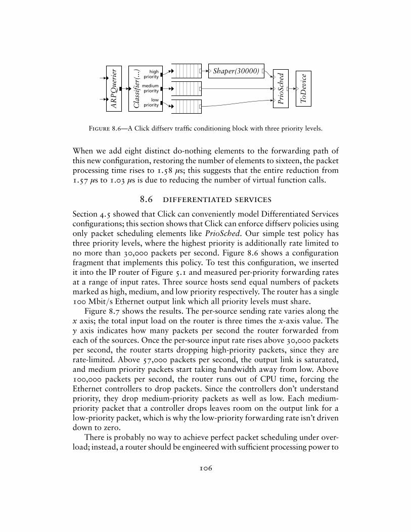
Cla
ssif
ier(
...)
AR
PQ
ueri
er Shaper(30000)
Pri
oSch
ed
ToD
evic
ehighpriority
mediumpriority
lowpriority
Figure 8.6—A Click diffserv traffic conditioning block with three priority levels.
When we add eight distinct do-nothing elements to the forwarding path ofthis new configuration, restoring the number of elements to sixteen, the packetprocessing time rises to 1.58 µs; this suggests that the entire reduction from1.57 µs to 1.03 µs is due to reducing the number of virtual function calls.
8.6 differentiated services
Section 4.5 showed that Click can conveniently model Differentiated Servicesconfigurations; this section shows that Click can enforce diffserv policies usingonly packet scheduling elements like PrioSched. Our simple test policy hasthree priority levels, where the highest priority is additionally rate limited tono more than 30,000 packets per second. Figure 8.6 shows a configurationfragment that implements this policy. To test this configuration, we insertedit into the IP router of Figure 5.1 and measured per-priority forwarding ratesat a range of input rates. Three source hosts send equal numbers of packetsmarked as high, medium, and low priority respectively. The router has a single100 Mbit/s Ethernet output link which all priority levels must share.
Figure 8.7 shows the results. The per-source sending rate varies along thex axis; the total input load on the router is three times the x-axis value. They axis indicates how many packets per second the router forwarded fromeach of the sources. Once the per-source input rate rises above 30,000 packetsper second, the router starts dropping high-priority packets, since they arerate-limited. Above 57,000 packets per second, the output link is saturated,and medium priority packets start taking bandwidth away from low. Above100,000 packets per second, the router runs out of CPU time, forcing theEthernet controllers to drop packets. Since the controllers don’t understandpriority, they drop medium-priority packets as well as low. Each medium-priority packet that a controller drops leaves room on the output link for alow-priority packet, which is why the low-priority forwarding rate isn’t drivendown to zero.
There is probably no way to achieve perfect packet scheduling under over-load; instead, a router should be engineered with sufficient processing power to
106
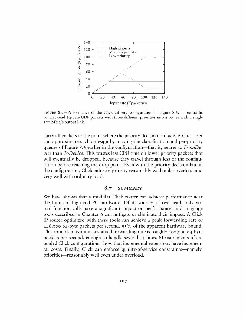
0
20
40
60
80
100
120
140
0 20 40 60 80 100 120 140
Forw
ardi
ng r
ate
(Kpa
cket
s/s)
Input rate (Kpackets/s)
High priorityMedium priorityLow priority
Figure 8.7—Performance of the Click diffserv configuration in Figure 8.6. Three trafficsources send 64-byte UDP packets with three different priorities into a router with a single100 Mbit/s output link.
carry all packets to the point where the priority decision is made. A Click usercan approximate such a design by moving the classification and per-priorityqueues of Figure 8.6 earlier in the configuration—that is, nearer to FromDe-vice than ToDevice. This wastes less CPU time on lower priority packets thatwill eventually be dropped, because they travel through less of the configu-ration before reaching the drop point. Even with the priority decision late inthe configuration, Click enforces priority reasonably well under overload andvery well with ordinary loads.
8.7 summary
We have shown that a modular Click router can achieve performance nearthe limits of high-end PC hardware. Of its sources of overhead, only vir-tual function calls have a significant impact on performance, and languagetools described in Chapter 6 can mitigate or eliminate their impact. A ClickIP router optimized with these tools can achieve a peak forwarding rate of446,000 64-byte packets per second, 95% of the apparent hardware bound.This router’s maximum sustained forwarding rate is roughly 400,000 64-bytepackets per second, enough to handle several t3 lines. Measurements of ex-tended Click configurations show that incremental extensions have incremen-tal costs. Finally, Click can enforce quality-of-service constraints—namely,priorities—reasonably well even under overload.
107
9Related work
The x-kernel [22] is a framework for implementing and composing networkprotocols. It is intended for use at end nodes, where packet motion is vertical(between the network and user level) rather than horizontal (between net-work interfaces). Like a Click router, an x-kernel configuration is a graph ofprocessing nodes, and packets are passed between nodes by virtual functioncalls. However, an x-kernel configuration graph is always acyclic and layered,as x-kernel nodes were intended to represent protocols in a protocol stack.This prevents cyclic configurations like our IP router. The x-kernel’s inter-node communication protocols are more complex than Click’s. Connectionsbetween nodes are bidirectional—packets travel up the graph to user level anddown the graph to the network. Packets pass alternately through “protocol”nodes and “session” nodes, where the session nodes correspond to end-to-endnetwork connections like TCP sessions. Bidirectional connections and sessionnodes are irrelevant to most routers.
Scout [30, 36] was designed for use as an operating system at end nodes,but it is better suited for routing than the x-kernel; for example, cyclic config-urations are partially supported, and session nodes are not mandatory. Execu-tion in Scout is centered on “paths”, sequences of packet processing functions.Each path has implicit queues on its inputs and outputs; it is not clear, there-fore, how many queues would appear in a complex configuration like the IProuter, which is not amenable to linearization. Each path is run by a singlethread and has a CPU priority, and packets are classified into the correct pathas early as possible. For example, TCP/IP packets containing MPEG data canbe routed immediately to the correct path, whose scheduling behavior mightbe specialized for MPEG. If desired, Click primitives can support some uses ofpaths: an early Classifier element could send MPEG-in-TCP-in-IP-in-Ethernettraffic into a special Queue, and the element that took packets off that Queue
108
could be scheduled appropriately for MPEG data. However, Scout supportsper-flow paths, where a path object is created for each individual networkflow. This allows its CPU scheduler to treat flows independently; Click’s CPUscheduler can only treat flow classes independently.
The UNIX System V STREAMS system [42] is also built from composablepacket processing modules. STREAMS modules include implicit queueing bydefault. Each module must be prepared for the next module’s queue to fillup, and to respond by queueing or discarding or deferring the processing ofincoming packets. Modules with multiple inputs or outputs must also makepacket scheduling decisions. STREAMS’ tendency to spread scheduling andqueueing logic throughout the configuration conflicts with a router’s need forprecise control over these functions.
FreeBSD contains a modular networking system called Netgraph [16]whose nodes resemble Click elements. Netgraph was designed for composingcoarse-grained modules such as PPP encapsulation and other framing proto-cols. Configurations are built up dynamically; there are commands that addand delete nodes, and that connect and disconnect “hooks” (the equivalentof ports), but no external specification for a configuration. This supportson-line configuration modification somewhat more naturally than Click, butthere is no way to analyze a Netgraph configuration off line or install a newconfiguration atomically.
ALTQ [6], a system for configurable traffic management, is also shippedwith FreeBSD. It contains several sophisticated queueing policies, but its con-figurability is limited to the specification of one queueing policy per outputinterface.
The router plugins system [10, 11] was designed to make IP routers moreextensible. A router plugin is a software module executed when a classifiermatches a particular flow. These classifiers can be installed at any of several“gates”. However, gates are fixed points in the IP forwarding path; there isno way to add new gates, or to control the path itself.
To the best of our knowledge, commercial routers are difficult to extend,either because they use specialized hardware [32, 35] or because their soft-ware is proprietary. However, open router software does not necessarily makea router easily extensible. A network administrator could, in principle, imple-ment new routing functions in Linux, but we expect few administrators havethe time or ability to modify the monolithic Linux kernel. Click’s modularitymakes it easy to take advantage of its extensibility.
The active networking research program allows anyone to write code thatwill affect a router [44, 48]. Click allows a trusted user to change any aspect
109

of a router; active networking allows untrusted packets to decide how theyshould be routed. The approaches are complementary, and Click may providea good platform for active network research.
Click’s polling implementation and device driver improvements were de-rived from previous work [14, 27, 28, 53].
110
10Conclusion
Click routers are modular, extensible, and flexible. Elements, the buildingblocks of router functionality, can support wide varieties of tasks through com-position. Click configurations for real routers, such as a standards-compliantIP router, are readable and extensible. We showed how adding support forscheduling and dropping policies, complex queueing, and transparent Webproxies can require simply adding a couple elements to the IP router, and howIP router elements are useful for other packet processing applications. Routerconfigurations are written in a simple, declarative language. Careful languagedesign means that router configurations are easy to process with tools, whichcan optimize configurations, check them for errors, or ensure they satisfysimple invariants. Our performance analysis shows that Click’s modularity iscompatible with good forwarding performance for PC hardware, and that ouroptimization tools are effective, reducing the Click IP router’s per-packet CPUtime by 34%. The optimized Click IP router’s steady-state forwarding rate is400,000 minimum-size packets per second; its peak forwarding rate is 95%the hardware’s apparent capacity. Last but not least, Click is fun to program.
Several universities are already using Click for research. At the Universityof Utah, researchers adopted it as a prototypical component-based systemagainst which they compared their own component architecture [41]. Studentsat Purdue University are modifying it to better support multicast and activenetworking [20]. The Mescal project at the University of California, Berkeleyused the Click IP router as the definition of IP routing, upon which they arebuilding their own modular router in a hardware-focused setting; they appearto have chosen Click because its high-level description of IP routing is so easyto understand [43]. At MIT, Click is in use as a mixed simulation/executionenvironment for the Grid ad-hoc routing system [9].
future work
Since the optimized Click IP router appears close to the performance limits ofour hardware, future performance work must focus on breaking these limits.
111
For instance, it might be a pleasant exercise to compile Click configurationsfor real router hardware—FPGAs or ASICs. Since elements tend to have com-pact specifications, they might correspond naturally to short definitions insome hardware description language. A Click-language tool might read inconfigurations and write out the corresponding hardware descriptions.
Of course, some configurations are still CPU-limited. Click currently runsin a single thread on a single processor. Taking advantage of a symmetric mul-tiprocessing platform might speed Click up dramatically. Its element structuremay facilitate dividing a configuration into regions, each of which could beactive on a different processor.
The tools described in Chapter 6 are relatively simple; they cannot, forexample, prove that every packet reaching a certain point in a configurationis an IP packet. Tools should be written that check configurations for suchhigh-level correctness properties. These properties are difficult to check andrequire more information about element semantics than the tools we havenow. The current system of writing tools based on informal element semanticshas many advantages, including that writing tools and elements is easy andrequires no theorem-proving expertise. Nevertheless, as tools are written thatestablish more complex properties, a parallel language for expressing elementsemantics in an integrated fashion may begin to make more sense.
summary
Click’s philosophy of components, a declarative language for combining com-ponents, and tools manipulating that language has been a success. The threeparts of the system—components, language, and tools—are in good balance.The system works well as a whole, with each part becoming more powerfulbecause of the others; for example, information elements are more useful be-cause tools can add them automatically, and compound elements are morepowerful because elements like ScheduleInfo were designed to support them.Click appears easy to learn, as witnessed by its use outside MIT. The mostimportant decision in its creation, I believe, was the initial division of thesystem into components and language. Without that early division, it wouldhave been tempting to make either the component architecture or the languagemore complicated than was necessary. With the early division, complexities inthe component architecture were resolved with help from the language, andvice versa, resulting in a simple, natural, and usable system. I would like tobuild more systems this way.
112
AElement glossary
This section lists 59 of the approximately 150 elements included with version1.1 of the Click software. Each entry follows this format:
ElementName(configuration arguments) Port types (push, pull, or agnostic).Port descriptions (packet types and numbers of ports). Description. (Op-tional reference to section with more detailed description.)
Some elements also have a reference to a section where more information canbe found. Detailed manuals for each element are accessible on line at http://www.pdos.lcs.mit.edu/click/doc/.
AddressInfo(name addrs, ...) No inputs or outputs. Creates shorthand namesfor IP and Ethernet addresses and IP network prefixes. (§4.7, p 61)
ARPQuerier(...) Push. First input takes IP packets, second input takes ARPresponses with Ethernet headers. Output emits ARP queries and IP-in-Ethernet packets. Uses ARP to find the Ethernet address corresponding toeach input IP packet’s destination IP address annotation; encapsulates thepacket in an Ethernet header with that destination Ethernet address.
ARPResponder(ip eth, ...) Agnostic. Input takes ARP queries, output emitsARP responses. Responds to ARP queries for IP address ip with the staticEthernet address eth.
CheckIPHeader(...) Agnostic. Input takes IP packets. Discards packets withinvalid IP length, source address, or checksum fields; forwards valid pack-ets unchanged.
CheckIPHeader2(...) Agnostic. Input takes IP packets. Discards packets withinvalid IP length or source address fields; forwards valid packets un-changed. Unlike CheckIPHeader, does not check the IP checksum.
113
Classifier(...) Push. Input takes any packet. Examines packet data accordingto a set of classifiers, one classifier per output port. Forwards packet tooutput port corresponding to the first classifier that matched. Exampleclassifier: “12/0800” checks that the packet’s data bytes 12 and 13 containsvalues 8 and 0, respectively. See also IPClassifier. (§4.2, p 45)
ControlSocket(type, addr) No inputs or outputs. Creates a socket and listensfor connections on that socket. Speaks a simple protocol allowing remotemachines to query read handlers and set write handlers. Only available atuser level.
Counter Agnostic. Input takes any packet; forwards packets unchanged. Itsread handlers provide information about the number of packets passedand their arrival rate.
DecIPTTL Agnostic, but second output is push. Input takes IP packets. Decre-ments input packets’ IP time-to-live field. If the packet is still live, incre-mentally updates IP checksum and sends modified packet to first output;if it has expired, sends unmodified packet to second output.
Discard Push. Discards all input packets.
DropBroadcasts Agnostic. Input takes any packet. Discards packets that ar-rived as link-level broadcasts; forwards others unchanged.
EtherEncap(p, ethersrc, etherdst) Agnostic. Input takes any packet, outputemits Ethernet packets. Encapsulates input packets in an Ethernet headerwith protocol p, source address ethersrc, and destination address etherdst.
EtherSpanTree Agnostic. Inputs take IEEE 802.1d messages. Implements theIEEE 802.1d spanning tree algorithm for Ethernet switches. (§5.3, p 70)
EtherSwitch Push. Inputs take Ethernet packets; one input and one outputper interface. Learning, forwarding Ethernet switch. Learns the interfacescorresponding to Ethernet addresses by examining input packets’ sourceaddresses; forwards packets to the correct output port, or broadcasts themif the destination Ethernet address is not yet known. (§5.3, p 69)
FixIPSrc(ip) Agnostic. Input takes IP packets. Sets the IP header’s source ad-dress field to the static IP address ip if the packet’s Fix IP Source annotationis set; forwards other packets unchanged.
114
FromDevice(devicename) Push. No inputs. Sends packets to its single outputas they arrive from a Linux device driver. Use FromDevice for devices thatdo not support polling. See also PollDevice.
FromLinux(devicename, ip/netmask) Push. No inputs. Installs into Linux afake Ethernet device devicename, and a routing table entry that sendspackets for ip/netmask to that fake device. The result is that packets gen-erated at the router host and destined for ip/netmask are emitted fromFromLinux’s single output as they arrive from Linux.
FrontDropQueue(n) Push input, pull output. Input takes any packet. Storespackets in a FIFO queue; maximum queue capacity is n. When a newpacket arrives on a full queue, the packet at the head of the queue isdropped rather than the new packet. See also Queue. (§2.5, p 21)
FTPPortMapper(...) Agnostic. Input takes TCP/IP packets representing anFTP control connection. Forwards most packets unchanged, but looksfor PORT commands embedded in passing packets. These commands arerewritten according to an IPRewriter pattern. (§4.6, p 57)
GetIPAddress(16) Agnostic. Input takes IP packets. Copies the IP header’sdestination address field (offset 16 in the IP header) into the destination IPaddress annotation; forwards packets unchanged.
HashSwitch(offset, length) Push. Input takes any packet; arbitrary numberof outputs. Forwards packet to one of its outputs, chosen by a hash of thepacket’s data—specifically, bytes [offset, offset + length).
ICMPError(ip, type, code) Agnostic. Input takes IP packets, output emitsICMP error packets. Encapsulates first part of input packet in ICMP errorheader with source address ip, error type type, and error code code. Setsthe Fix IP Source annotation on output packets.
Idle Agnostic. Any number of inputs and outputs. Discards all packets as theyarrive, and always returns a null pointer in response to pull requests.
IPClassifier(...) Push. Input takes IP packets. Examines packet data accordingto a set of classifiers, one classifier per output port. Forwards packet tooutput port corresponding to the first classifier that matched. Exampleclassifier: “ip src 1.0.0.1 and dst tcp port www” checks that the packet’ssource IP address is 1.0.0.1, its IP protocol is 6 (TCP), and its destinationTCP port is 80. See also Classifier and IPFilter. (§4.2, p 46)
115
IPEncap(p, ipsrc, ipdst) Agnostic. Input takes any packet, output emits IPpackets. Encapsulates input packets in an IP header with protocol p, sourceaddress ipsrc, and destination address ipdst.
IPFilter(...) Push. Input takes IP packets. Examines packet data according toa set of classifiers, where each classifier contains an action such as “allow”(meaning forward to first output port) or “drop”. Performs the actionof the first classifier that matched. Example action and classifier: “allowip src 1.0.0.1 and dst tcp port www” checks that the packet’s source IPaddress is 1.0.0.1, its IP protocol is 6 (TCP), and its destination TCP portis 80; if this is true, the packet is forwarded to the first output. See alsoIPClassifier. (§5.4, p 70)
IPFragmenter(mtu) Push. Input takes IP packets. Fragments IP packets largerthan mtu; sends fragments, and packets smaller than mtu, to first out-put. Too-large packets with the don’t-fragment IP header flag set are sentunmodified to the second output.
IPGWOptions Agnostic, but second output is push. Input takes IP packets.Processes IP Record Route and Timestamp options; packets with invalidoptions are sent to the second output.
IPRewriter(...) Push. Inputs take IP packets; any number of inputs and out-puts. Rewrites TCP/IP and UDP/IP packets according to specified rewriterules. See also TCPRewriter. (§4.6, p 54)
IPRewriterPatterns(...) No inputs or outputs. Stores shared IPRewriter pat-terns. (§4.6, p 58)
LookupIPRoute(table) Push. Input takes IP packets with valid destinationIP address annotations. Arbitrary number of outputs. Looks up inputpackets’ destination annotations in a static routing table specified in theconfiguration string. Forwards each packet to the output port specifiedin the resulting routing table entry; sets its destination annotation to thespecified gateway address, if any.
Meter(r) Push. Input takes any packet. Sends all packets to first output ifrecent input rate averages < r, second output otherwise. Multiple ratearguments are allowed. See also RatedSplitter.
Null Agnostic. Input takes any packet; forwards every input packet to itsoutput unchanged.
116
Paint(p) Agnostic. Input takes any packet. Sets each input packet’s paintannotation to p before forwarding it.
PaintTee(p) Agnostic, but second output is push. Input takes any packet.Forwards packets with paint annotation p to both outputs; otherwise justto first.
PollDevice(devicename) Push. No inputs. Sends packets to its single output asthey arrive from a Linux device driver. Uses polling. See also FromDevice.(§7.1, p 91)
PrioSched Pull. Inputs take any packet; one output port, arbitrary number ofinput ports. Responds to pull requests by trying inputs in numeric order,returning the first packet it receives. Thus, lower-numbered inputs havepriority. (§4.3, p 47)
Queue(n) Push input, pull output. Input takes any packet. Stores packets ina FIFO queue; maximum queue capacity is n. See also FrontDropQueue.(§2.5, p 21)
RandomBitErrors(prob, action) Agnostic. Input takes any packet. Changeseach bit on each input packet with probability prob. Action determinesthe kind of change: set sets bits to 1, clear sets bits to 0, and flip flips bits.
RatedSource(data, rate, count) Push. No inputs; output emits packets con-taining data as data. Sends rate packets per second up to a maximum ofcount packets.
RatedSplitter(rate) Push. Input takes any packet. Forwards up to rate inputpackets to its first output unchanged. Any remaining packets are forwardedto the second output. (§4.5, p 49)
RED(minthresh, maxthresh, maxp) Agnostic. Input takes any packet. Dropspackets probabilistically according to the Random Early Detection algo-rithm [18] with the given parameters; forwards other packets unchanged.Examines nearby router queue lengths when making its drop decision.(§4.4, p 48)
RoundRobinIPMapper(...) No inputs or outputs. A round-robin IPRewritermapper, useful, for example, for load balancing. (§4.6, p 57)
117
RoundRobinSched Pull. Inputs take any packet; one output port, arbitrarynumber of input ports. Responds to pull requests by trying inputs in round-robin order; returns the first packet it receives. It first tries the input portjust after the one that succeeded on the last pull request. (§4.3, p 47)
ScheduleInfo(elementname param, ...) No inputs or outputs. Specifies ele-ments’ initial task queue scheduling parameters by element name. Eachscheduling parameter is a real number; an element with parameter 2p willbe scheduled twice as often as an element with parameter p. (§4.7, p 59)
ScheduleLinux No inputs or outputs. Places itself on the task queue, andreturns to Linux’s scheduler every time it is run.
SetIPAddress(ip) Agnostic. Input takes IP packets. Sets each packet’s destina-tion IP address annotation to the static IP address ip. Forwards modifiedpackets to first output.
SetIPDSCP(c) Agnostic. Input takes IP packets. Sets each packet’s IP diff-serv code point field [33] to c and incrementally updates the IP headerchecksum. Forwards modified packets to first output.
Shaper(n) Pull. Input takes any packet. Simple pull traffic shaper: forwardsat most n pull requests per second to its input. Pull requests over that rateget a null pointer in response.
StaticPullSwitch(p) Pull. Input takes any packet; arbitrary number of inputs.Forwards each pull request to input port p. (§3.5, p 40)
StaticSwitch(p) Push. Input takes any packet; arbitrary number of outputs.Forwards each input packet to output port p. (§3.5, p 40)
Strip(n) Agnostic. Input takes any packet. Strips off each packet’s first n bytes;forwards modified packets to first output.
StripIPHeader Agnostic. Input takes IP packets. Strips off each packet’s IPheader, including any options; forwards modified packets to first output.
Suppressor Agnostic. Inputs take any packet; arbitrary number of input ports,same number of output ports. Normally forwards packets arriving on eachinput port to the corresponding output port. A method interface allowsother elements to ask Suppressor to drop packets arriving on particularinput ports. (§5.3, p 70)
118
TCPRewriter(...) Push. Inputs take TCP/IP packets; any number of inputs andoutputs. Rewrites TCP/IP packets according to specified rewrite rules. Thiselement supports sequence number rewriting as well as flow ID rewriting.See also IPRewriter. (§4.6, p 57)
Tee(n) Push. Input takes any packet; n output ports. Forwards each inputpacket to all n output ports.
ToDevice(device) Pull. Input takes Ethernet packets; no outputs. Hands pack-ets to a Linux device driver for transmission. Activates pull requests onlywhen the device is ready.
ToLinux Push. Input takes Ethernet packets; Linux will ignore the Ethernetheader except for the protocol field. No outputs. Hands input packets toLinux’s default network input software.
UDPIPEncap(ipsrc, srcport, ipdst, dstport) Agnostic. Input takes any packet,output emits UDP/IP packets. Encapsulates input packets in a UDP-in-IPheader with source address ipsrc, source port srcport, destination addressipdst, and destination port dstport.
Unqueue Pull input, push output. Input takes any packet. Places itself onthe task queue; whenever it is scheduled, pulls packets from its input andforwards them to its output.
119
BLanguage grammar
B.1 lexical issues
Click identifiers are nonempty sequences of letters, numbers, underscores ‘_’,at-signs ‘@’, and slashes ‘/’ that do not begin with a slash. The system uses‘@’ and ‘/’ for special purposes: ‘@’ in constructed names for anonymouselements and ‘/’ in names for components of compound elements. Users arediscouraged from using these characters in their own identifiers. Identifiersare case-sensitive.
The keywords ‘connectiontunnel’, ‘elementclass’ and ‘require’ may notbe used as identifiers. The normal identifiers ‘input’ and ‘output’ have specialmeaning inside compound element definitions.
The following characters and multi-character sequences are single Clicktokens: -> :: ; , ( ) [ ] { } | || ...
Whitespace and comments, as defined by C++, separate Click tokens. Ei-ther form of comment—from ‘//’ to the end of the line, or from ‘/*’ to thenext ‘*/’—terminates an identifier, so this Click fragment
an/identifier/with/slashes//too/many
has an identifier ‘an/identifier/with/slashes’ and a comment ‘//too/many’.No identifier contains two consecutive slashes.
Parameters look like Perl variables. A parameter consists of a dollar sign‘$’ followed by one or more letters, numbers, and underscores.
A configuration string (config-string in the grammar) starts immediatelyfollowing a left parenthesis ‘(’ and continues up to the next unbalanced rightparenthesis ‘)’. However, parentheses inside single or double quotes or com-ments do not affect balancing. Here are several examples; in each case, theconfiguration string consists of the underlined text.
120
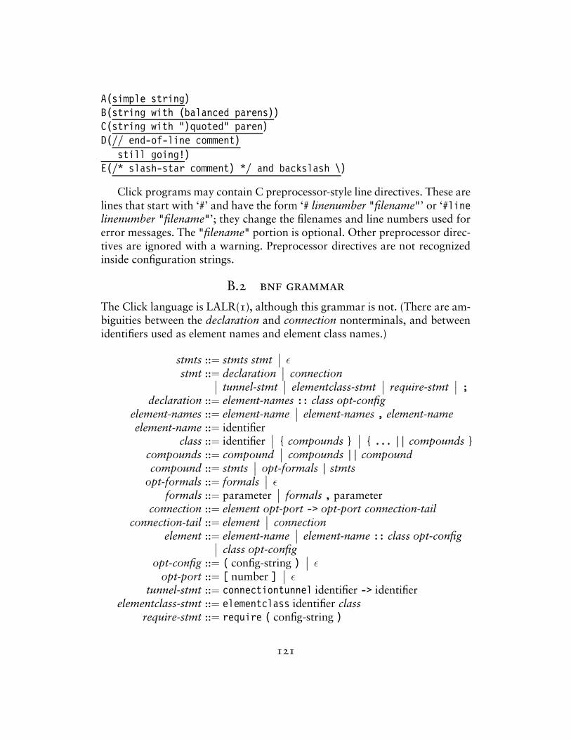
A(simple string)B(string with (balanced parens))C(string with ")quoted" paren)D(// end-of-line comment)
still going!)E(/* slash-star comment) */ and backslash \)
Click programs may contain C preprocessor-style line directives. These arelines that start with ‘#’ and have the form ‘# linenumber "filename"’ or ‘#linelinenumber "filename"’; they change the filenames and line numbers used forerror messages. The "filename" portion is optional. Other preprocessor direc-tives are ignored with a warning. Preprocessor directives are not recognizedinside configuration strings.
B.2 bnf grammar
The Click language is LALR(1), although this grammar is not. (There are am-biguities between the declaration and connection nonterminals, and betweenidentifiers used as element names and element class names.)
stmts ::= stmts stmt∣∣ ε
stmt ::= declaration∣∣ connection∣∣ tunnel-stmt∣∣ elementclass-stmt
∣∣ require-stmt∣∣ ;
declaration ::= element-names :: class opt-configelement-names ::= element-name
∣∣ element-names , element-nameelement-name ::= identifier
class ::= identifier∣∣ { compounds }
∣∣ { ... || compounds }compounds ::= compound
∣∣ compounds || compoundcompound ::= stmts
∣∣ opt-formals | stmtsopt-formals ::= formals
∣∣ εformals ::= parameter
∣∣ formals , parameterconnection ::= element opt-port -> opt-port connection-tail
connection-tail ::= element∣∣ connection
element ::= element-name∣∣ element-name :: class opt-config∣∣ class opt-config
opt-config ::= ( config-string )∣∣ ε
opt-port ::= [ number ]∣∣ ε
tunnel-stmt ::= connectiontunnel identifier -> identifierelementclass-stmt ::= elementclass identifier class
require-stmt ::= require ( config-string )
121
Bibliography
[1] A. V. Aho, R. Sethi, and J. D. Ullman. Compilers: Principles, Techniques,and Tools. Addison-Wesley, Reading, Massachusetts, 1986.
[2] Mary L. Bailey, Burra Gopal, Michael A. Pagels, and Larry L. Peterson.PathFinder: A pattern-based packet classifier. In Proc. 1st USENIXSymposium on Operating Systems Design and Implementation (OSDI’94), pages 115–123, October 1994.
[3] F. Baker. Requirements for IP Version 4 routers. RFC 1812, InternetEngineering Task Force, June 1995. ftp://ftp.ietf.org/rfc/rfc1812.txt.
[4] Andrew Begel, Steven McCanne, and Susan L. Graham. BPF+: Exploitingglobal data-flow optimization in a generalized packet filter architecture.In Proc. ACM SIGCOMM ’99 Conference on Applications, Technolo-gies, Architectures, and Protocols for Computer Communication, pages123–134, August 1999.
[5] S. Blake, D. Black, M. Carlson, E. Davies, Z. Wang, and W. Weiss. Anarchitecture for differentiated services. RFC 2475, Internet EngineeringTask Force, December 1998. ftp://ftp.ietf.org/rfc/rfc2475.txt.
[6] Kenjiro Cho. A framework for alternate queueing: towards traffic man-agement by PC-UNIX based routers. In Proc. USENIX 1998 AnnualTechnical Conference, pages 247–258, June 1998.
[7] Cisco Corporation. Distributed WRED. Technical report, 1999.http://www.cisco.com/univercd/cc/td/doc/product/software/ios111/cc111/wred.htm, as of January 2000.
122
[8] David Clark. The structuring of systems using upcalls. In Proc. of the10th ACM Symposium on Operating Systems Principles (SOSP), pages171–180, December 1985.
[9] Douglas S. J. De Couto and Robert Morris. Personal communication,2000.
[10] Dan Decasper, Zubin Dittia, Guru Parulkar, and Bernhard Plattner.Router plugins: A software architecture for next generation routers. InProc. ACM SIGCOMM ’98 Conference on Applications, Technologies,Architectures, and Protocols for Computer Communication, pages 229–240, October 1998.
[11] Daniel S. Decasper. A software architecture for next generation routers.PhD thesis, Swiss Federal Institute of Technology, Zurich, 1999.
[12] Mikael Degermark, Andrej Brodnik, Svante Carlsson, and Stephen Pink.Small forwarding tables for fast routing lookups. In Proc. ACM SIG-COMM ’97 Conference on Applications, Technologies, Architectures,and Protocols for Computer Communication, pages 3–14, October1997.
[13] Digital Equipment Corporation. DIGITAL Semiconductor 21140A PCIFast Ethernet LAN Controller Hardware Reference Manual, March1998. http://developer.intel.com/design/network/manuals.
[14] P. Druschel, L. Peterson, and B. Davie. Experiences with a high-speednetwork adaptor: A software perspective. In Proc. ACM SIGCOMM’94 Conference on Communications Architectures, Protocols and Appli-cations, pages 2–13, August 1994.
[15] K. Egevang and P. Francis. The IP Network Address Translator (NAT).RFC 1631, Internet Engineering Task Force, May 1994. ftp://ftp.ietf.org/rfc/rfc1631.txt.
[16] Julian Elischer and Archie Cobbs. The Netgraph networking system.Technical report, Whistle Communications, January 1998. http://www.elischer.com/netgraph/, as of July 2000.
[17] Dawson Engler and M. Frans Kaashoek. DPF: Fast, flexible message de-multiplexing using dynamic code generation. In Proc. ACM SIGCOMM’96 Conference on Applications, Technologies, Architectures, and Pro-tocols for Computer Communication, pages 53–59, August 1996.
123

[18] Sally Floyd and Van Jacobson. Random early detection gateways forcongestion avoidance. IEEE/ACM Transactions on Networking, 1(4):397–413, August 1993.
[19] Christopher W. Fraser, Robert R. Henry, and Todd A. Proebsting. Burg—fast optimal instruction selection and tree parsing. SIGPLAN Notices,27(4):68–76, April 1992.
[20] Prem Gopalan and Saurabh Sandhir. Personal communication, 2000.
[21] Michael Hasenstein. IP network address translation. Diplomarbeit,Technische Universitat Chemnitz, Chemnitz, Germany, 1997. Availableon line at http://www.suse.de/˜mha/linux-ip-nat/diplom/nat.htmlas of November 2000.
[22] Norman C. Hutchinson and Larry L. Peterson. The x-kernel: an ar-chitecture for implementing network protocols. IEEE Transactions onSoftware Engineering, 17(1):64–76, January 1991.
[23] Intel Corporation. Pentium Pro Family Developer’s Manual, Volume 3,1996. http://developer.intel.com/design/pro/manuals.
[24] T. V. Lakshman, Arnold Neidhardt, and Teunis J. Ott. The drop fromfront strategy in TCP and in TCP over ATM. In Proc. IEEE INFOCOM,volume 3, pages 1242–1250, March 1996.
[25] Xiaoming Liu, Christoph Kreitz, Robbert van Renesse, Jason Hickey,Mark Hayden, Kenneth Birman, and Robert Constable. Building reli-able, high-performance communication systems from components. InProc. 17th ACM Symposium on Operating Systems Principles (SOSP),pages 80–92, December 1999.
[26] P. E. McKenney. Stochastic fairness queueing. In Proc. IEEE INFO-COM, volume 2, pages 733–740, June 1990.
[27] David L. Mills. The Fuzzball. In SIGCOMM ’88, Proc. ACM Symposiumon Communications Architectures & Protocols, pages 115–122, August1988.
[28] Jeffrey C. Mogul and K. K. Ramakrishnan. Eliminating receive livelockin an interrupt-driven kernel. ACM Transactions on Computer Systems,15(3):217–252, August 1997.
124
[29] Robert Morris, Eddie Kohler, John Jannotti, and M. Frans Kaashoek.The Click modular router. In Proc. 17th ACM Symposium on OperatingSystems Principles (SOSP), pages 217–231, December 1999.
[30] David Mosberger and Larry L. Peterson. Making paths explicit in theScout operating system. In Proc. 2nd Symposium on Operating SystemsDesign and Implementation (OSDI ’96), pages 153–167, October 1996.
[31] David Mosberger, Larry L. Peterson, Patrick G. Bridges, and SeanO’Malley. Analysis of techniques to improve protocol processing latency.In Proc. ACM SIGCOMM ’96 Conference on Applications, Technolo-gies, Architectures, and Protocols for Computer Communication, pages73–84, August 1996.
[32] Peter Newman, Greg Minshall, and Thomas L. Lyon. IP switching—ATM under IP. IEEE/ACM Transactions on Networking, 6(2):117–129,April 1998.
[33] K. Nichols, S. Blake, F. Baker, and D. Black. Definition of the Differen-tiated Services field (DS field) in the IPv4 and IPv6 headers. RFC 2474,Internet Engineering Task Force, December 1998. ftp://ftp.ietf.org/rfc/rfc2474.txt.
[34] NS. UCB/LBNL/VINT network simulator NS homepage. Available fromhttp://www-mash.cs.berkeley.edu/ns/.
[35] Craig Partridge, Philip P. Carvey, Ed Burgess, Isidro Castineyra, TomClarke, Lise Graham, Michael Hathaway, Phil Herman, Allen King, SteveKohalmi, Tracy Ma, John Mcallen, Trevor Mendez, Walter C. Milliken,Ronald Pettyjohn, John Rokosz, Joshua Seeger, Michael Sollins, SteveStorch, Benjamin Tober, Gregory D. Troxel, David Waitzman, and ScottWinterble. A 50-Gb/s IP router. IEEE/ACM Transactions on Network-ing, 6(3):237–248, June 1998.
[36] Larry L. Peterson, Scott C. Karlin, and Kai Li. OS support for general-purpose routers. In Proc. 7th Workshop on Hot Topics in OperatingSystems (HotOS-VII), pages 38–43. IEEE Computer Society TechnicalCommittee on Operating Systems, March 1999.
[37] J. Postel. Internet Protocol. RFC 791, Internet Engineering Task Force,September 1981. ftp://ftp.ietf.org/rfc/rfc0791.txt.
125
[38] J. Postel. Internet Control Message Protocol. RFC 792, InternetEngineering Task Force, September 1981. ftp://ftp.ietf.org/rfc/rfc0792.txt.
[39] J. Postel and J. Reynolds. File Transfer Protocol (FTP). RFC 959,Internet Engineering Task Force, October 1985. ftp://ftp.ietf.org/rfc/rfc0959.txt.
[40] Darren Reed. IP Filter TCP/IP packet filtering package. Technical report,2000. http://coombs.anu.edu.au/˜avalon/, as of November 2000.
[41] Alastair Reid, Matthew Flatt, Leigh Stoller, Jay Lepreau, and Eric Eide.CpU: Component composition for systems software. In Proc. 4th Sym-posium on Operating Systems Design and Implementation (OSDI 2000),October 2000.
[42] D. M. Ritchie. A stream input-output system. AT&T Bell LaboratoriesTechnical Journal, 63(8):1897–1910, October 1984.
[43] Michael Shilman. Personal communication, 2000.
[44] Jonathan M. Smith, Kenneth L. Calvert, Sandra L. Murphy, Hilarie K.Orman, and Larry L. Peterson. Activating networks: a progress report.IEEE Computer, 32(4):32–41, April 1999.
[45] P. Srisuresh and D. Gan. Load sharing using IP Network Address Trans-lation (LSNAT). RFC 2391, Internet Engineering Task Force, August1998. ftp://ftp.ietf.org/rfc/rfc2391.txt.
[46] P. Srisuresh and M. Holdrege. IP Network Address Translator (NAT)terminology and considerations. RFC 2663, Internet Engineering TaskForce, August 1999. ftp://ftp.ietf.org/rfc/rfc2663.txt.
[47] P. Srisuresh, G. Tsirtsis, P. Akkiraju, and A. Hefferman. DNS exten-sions to Network Address Translators (DNS ALG). RFC 2694, InternetEngineering Task Force, September 1999. ftp://ftp.ietf.org/rfc/rfc2694.txt.
[48] David L. Tennenhouse, Jonathan M. Smith, W. David Sincoskie, David J.Wetherall, and Gary J. Minden. A survey of active network research.IEEE Communications Magazine, 35(1):80–86, January 1997.
[49] J. R. Ullmann. An algorithm for subgraph isomorphism. Journal of theACM, 23(1):31–42, January 1976.
126
[50] Carl A. Waldspurger and William E. Weihl. Stride scheduling: deter-ministic proportional-share resource management. Technical MemoMIT/LCS/TM-528, MIT Laboratory for Computer Science, June 1995.
[51] Marcel Waldvogel, George Varghese, Jon Turner, and Bernhard Plattner.Scalable high speed IP routing lookups. In Proc. ACM SIGCOMM ’97Conference on Applications, Technologies, Architectures, and Protocolsfor Computer Communication, pages 25–38, October 1997.
[52] Mark N. Wegman and Kenneth Zadeck. Constant propagation withconditional branches. ACM Transactions on Programming Languagesand Systems, 13(2):181–210, April 1991.
[53] John Wroclawski. Fast PC routers. Technical report, MIT LCS AdvancedNetwork Architecture Group, January 1997. http://mercury.lcs.mit.edu/PC-Routers/pcrouter.html, as of July 2000.
[54] Elizabeth D. Zwicky, Simon Cooper, and D. Brent Chapman. BuildingInternet Firewalls, Second Edition. O’Reilly and Associates, Sebastopol,California, 2000.
127