The Cherenkov Telescope Array Large Size Telescope 22, 28040 Madrid, Spain 5 Instituto de...
4
33 RD I NTERNATIONAL COSMIC RAY CONFERENCE,RIO DE JANEIRO 2013 THE ASTROPARTICLE PHYSICS CONFERENCE The Cherenkov Telescope Array Large Size Telescope G. AMBROSI 17 , Y. AWANE 12 , H. BABA 6 , A. BAMBA 1 , M. BARCEL ´ O 8 , U. BARRES DE ALMEIDA 3 , J.A. BARRIO 25 , O. BLANCH BIGAS 8 , J. BOIX 8 , L. BRUNETTI 13 , E. CARMONA 4 , E. CHABANNE 13 , M. CHIKAWA 10 , P. COLIN 14 , J.L. CONTERAS 25 , J. CORTINA 8 , F. DAZZI 32 , A. DEANGELIS 24 , G. DELEGLISE 13 , C. DELGADO 4 , C. D´ IAZ 4 , F. DUBOIS 25 , A. FIASSON 13 , D. FINK 14 , N. FOUQUE 13 , L. FREIXAS 4 , C. FRUCK 14 , A. GADOLA 29 , R. GARC´ IA 5 , D. GASCON 26 , N. GEFFROY 13 , N. GIGLIETTO 2 , F. GIORDANO 2 , F. GRA ˜ NENA 8 , S. GUNJI 31 , R. HAGIWARA 31 , N. HAMER 4 , Y. HANABATA 7 , T. HASSAN 25 , K. HATANAKA 12 , T. HAUBOLD 14 , M. HAYASHIDA 7 , R. HERMEL 13 , D. HERRANZ 25 , K. HIROTANI 7 , S. I NOUE 7 , Y. I NOUE 7 , K. I OKA 9 , C. JABLONSKI 14 , M. KAGAYA 6 , H. KATAGIRI 6 , T. KISHIMOTO 12 , K. KODANI 22 , K. KOHRI 9 , Y. KONNO 12 , S. KOYAMA 21 , H. KUBO 12 , J. KUSHIDA 22 , G. LAMANNA 13 , T. LE FLOUR 13 , M. L ´ OPEZ-MOYA 25 , R. L ´ OPEZ 8 , E. LORENZ 14 , P. MAJUMDAR 20 , A. MANALAYSAY 29 , M. MARIOTTI 16 , G. MART´ INEZ 4 , M. MART´ INEZ 8 , D. MAZIN 14 , J.M. MIRANDA 23 , R. MIRZOYAN 14 , I. MONTEIRO 13 , A. MORALEJO 8 , K. MURASE 7 , S. NAGATAKI 19 , D. NAKAJIMA 14 , T. NAKAMORI 30 , K. NISHIJIMA 22 , K. NODA 14 , A. NOZATO 10 , Y. OHIRA 9 , M. OHISHI 7 , H. OHOKA 7 , A. OKUMURA 15 , R. ORITO 27 , J.L. PANAZOL 13 , D. PANEQUE 14 , R. PAOLETTI 18 , J.M. PAREDES 26 , G. PAULETTA 24 , S. PODKLADKIN 14 , J. PRAST 13 , R. RANDO 16 , O. REIMANN 14 , M. RIB ´ O 26 , S. ROSIER-LEES 13 , K. SAITO 7 , T. SAITO 12 , Y. SAITO 22 , N. SAKAKI 7 , R. SAKONAKA 10 , A. SANUY 26 , H. SASAKI 11 , M. SAWADA 1 , V. SCALZOTTO 16 , S. SCHULTZ 16 , T. SCHWEIZER 14 , T. SHIBATA 1 , S. SHU 10 , J. SIEIRO 26 , V. STAMATESCU 8 , S. STEINER 29 , U. STRAUMANN 29 , R. SUGAWARA 27 , H. TAJIMA 15 , H. TAKAMI 9 , S. TANAKA 6 , M. TANAKA 9 , L.A. TEJEDOR 25 , Y. TERADA 21 , M. TESHIMA 7,14 , T. TOTANI 28 , H. UENO 21 , K. UMEHARA 6 , A. VOLLHARDT 29 , R. WAGNER 14 , H. WETTESKIND 14 , T. YAMAMOTO 11 , R. YAMAZAKI 1 , A. YOSHIDA 1 , T. YOSHIDA 6 , T. YOSHIKOSHI 7 FOR THE CHERENKOV TELESCOPE ARRAY CONSORTIUM. 1 Department of Physics and Mathematics, Aoyama Gakuin University, Fuchinobe, Sagamihara, Kanagawa, 229-8558, Japan 2 INFN Sezione di Bari, via Orabona 4, I-70126 Bari, Italy 3 Centro Brasileiro de Pesquisas Fisicas (CBPF/MCTI), Rua Xavier Sigaud 150, RJ 22290-180, Rio de Janeiro, Brazil 4 CIEMAT, Avda. Complutense 22, 28040 Madrid, Spain 5 Instituto de Astrof´ ısica de Canarias (IAC), Via Lactea, 38205 La Laguna, Tenerife, Spain 6 Faculty of Science, Ibaraki University, Mito, Ibaraki, 310-8512, Japan 7 Institute for Cosmic Ray Research (ICRR), University of Tokyo, 5-1-5, Kashi-wanoha, Kashiwa, Chiba 277-8582, Japan 8 Institut de F´ ısica d’Altes Energies (IFAE), Edifici Cn, Campus UAB, 08193 Bellaterra, Spain 9 Institute of Particle and Nuclear Studies, KEK, 1-1 Oho, Tsukuba, 305-0801, Japan 10 Department of Physics, Kinki University, Kowakae, Higashi-Osaka 577-8502, Japan 11 Department of Physics, Konan University, Kobe, Hyogo, 658-8501 Japan 12 Kyoto University, Sakyo-ku, Kyoto 606-8502, Japan 13 LAPP, Universit´ e de Savoie, CNRS/IN2P3, 9 Chemin de Bellevue - BP 110, 74941 Annecy-le-Vieux Cedex, France 14 Max-Planck-Institut f¨ ur Physik, F ¨ ohringer Ring 6, 80805 M¨ unchen, Germany 15 Nagoya University, Chikusa-ku, Nagoya 464-8602, Japan 16 Dipartimento di Fisica - Universit´ a degli Studi di Padova, Via Marzolo 8, 35131 Padova, Italy 17 INFN Sezione di Perugia, Via A. Pascoli, Perugia, Italy 18 Universit´ a di Siena & INFN Sezione di Pisa, Via Roma 56, 53100 Siena, Italy 19 RIKEN, Advanced Science Institute, 2-1 Hirosawa, Wako, Saitama 351-0198, Japan 20 Saha Institute of Nuclear Physics (SINP), Kolkata, India 21 Saitama University, 255 Simo-Ohkubo, Sakura-ku, Saitama city, Saitama 338-8570, Japan 22 Department of Physics, Tokai University, 1117 Kita-Kaname, Hiratsuka, Kanagawa 259-1292, Japan 23 Grupo de Electr ´ onica, Universidad Complutense de Madrid, Av. Complutense s/n, 28040 Madrid, Spain 24 University of Udine & INFN Sezione di Trieste, Via delle Scienze 208, 33100 Udine, Italy 25 Grupo de Altas Energ´ ıas, Universidad Complutense de Madrid, Av Complutense s/n, 28040 Madrid, Spain 26 Departament d’Astronomia i Meteorologia (ICC-UB), Universitat de Barcelona, Mart´ ı i Franqu` es, 1, 08028, Barcelona, Spain 27 Institute of Socio-Arts and Sciences, University of Tokushima, Tokushima 770-8502, Japan 28 Department of Physics, Graduate School of Science, University of Tokyo, 7-3-1 Hongo, Bunkyo-ku, Tokyo 113-0033, Japan 29 Physik-Institut, Universit¨ at Z¨ urich, Winterthurerstrasse 190, 8057 Z¨ urich, Switzerland 30 Faculty of Science and Engineering, Waseda University, Shinjuku, Tokyo 169-8555, Japan 31 Department of Physics, Yamagata University, Yamagata, Yamagata 990-8560, Japan 32 INFN Sezione di Padova, Via Marzolo 8, 35131 Padova, Italy. [email protected] Abstract: The two arrays of the Very High Energy gamma-ray observatory Cherenkov Telescope Array (CTA) will include four Large Size Telescopes (LSTs) each with a 23 m diameter dish and 28 m focal distance. These telescopes will enable CTA to achieve a low-energy threshold of 20 GeV, which is critical for important studies in astrophysics, astroparticle physics and cosmology. This work presents the key specifications and performance of the current LST design in the light of the CTA scientific objectives. Keywords: Gamma Ray, VHE Gamma Ray, Instruments arXiv:1307.4565v1 [astro-ph.IM] 17 Jul 2013
Transcript of The Cherenkov Telescope Array Large Size Telescope 22, 28040 Madrid, Spain 5 Instituto de...
33RD INTERNATIONAL COSMIC RAY CONFERENCE, RIO DE JANEIRO 2013THE ASTROPARTICLE PHYSICS CONFERENCE
The Cherenkov Telescope Array Large Size TelescopeG. AMBROSI17, Y. AWANE12, H. BABA6, A. BAMBA1 , M. BARCELO8 , U. BARRES DE ALMEIDA3 , J.A. BARRIO25,O. BLANCH BIGAS8 , J. BOIX8 , L. BRUNETTI13, E. CARMONA4 , E. CHABANNE13 , M. CHIKAWA10, P. COLIN14,J.L. CONTERAS25, J. CORTINA8, F. DAZZI32 , A. DEANGELIS24 , G. DELEGLISE13, C. DELGADO4, C. D IAZ4 ,F. DUBOIS25, A. FIASSON13, D. FINK14, N. FOUQUE13, L. FREIXAS4, C. FRUCK14 , A. GADOLA29 , R. GARCIA5,D. GASCON26, N. GEFFROY13, N. GIGLIETTO2 , F. GIORDANO2, F. GRANENA8, S. GUNJI31, R. HAGIWARA31 ,N. HAMER4, Y. HANABATA7, T. HASSAN25 , K. HATANAKA12, T. HAUBOLD14 , M. HAYASHIDA7, R. HERMEL13 ,D. HERRANZ25 , K. HIROTANI7, S. INOUE7 , Y. INOUE7 , K. IOKA9, C. JABLONSKI14 , M. KAGAYA6, H. KATAGIRI6 ,T. KISHIMOTO12 , K. KODANI22 , K. KOHRI9 , Y. KONNO12 , S. KOYAMA21 , H. KUBO12 , J. KUSHIDA22 , G. LAMANNA13 ,T. LE FLOUR13, M. LOPEZ-MOYA25, R. LOPEZ8, E. LORENZ14 , P. MAJUMDAR20 , A. MANALAYSAY29,M. MARIOTTI16 , G. MARTINEZ4 , M. MARTINEZ8 , D. MAZIN14 , J.M. MIRANDA23 , R. MIRZOYAN14 , I. MONTEIRO13 ,A. MORALEJO8 , K. MURASE7, S. NAGATAKI19 , D. NAKAJIMA14 , T. NAKAMORI30, K. NISHIJIMA22 , K. NODA14,A. NOZATO10 , Y. OHIRA9 , M. OHISHI7 , H. OHOKA7 , A. OKUMURA15 , R. ORITO27 , J.L. PANAZOL13 , D. PANEQUE14 ,R. PAOLETTI18, J.M. PAREDES26, G. PAULETTA24, S. PODKLADKIN14, J. PRAST13, R. RANDO16 , O. REIMANN14,M. RIBO26 , S. ROSIER-LEES13 , K. SAITO7 , T. SAITO12 , Y. SAITO22, N. SAKAKI7 , R. SAKONAKA10 , A. SANUY26,H. SASAKI11 , M. SAWADA1 , V. SCALZOTTO16 , S. SCHULTZ16 , T. SCHWEIZER14 , T. SHIBATA1 , S. SHU10 , J. SIEIRO26 ,V. STAMATESCU8 , S. STEINER29 , U. STRAUMANN29, R. SUGAWARA27 , H. TAJIMA15 , H. TAKAMI9, S. TANAKA6 ,M. TANAKA9, L.A. TEJEDOR25, Y. TERADA21 , M. TESHIMA7,14, T. TOTANI28 , H. UENO21, K. UMEHARA6 ,A. VOLLHARDT29, R. WAGNER14, H. WETTESKIND14 , T. YAMAMOTO11 , R. YAMAZAKI1 , A. YOSHIDA1,T. YOSHIDA6, T. YOSHIKOSHI7 FOR THE CHERENKOV TELESCOPE ARRAY CONSORTIUM.1 Department of Physics and Mathematics, Aoyama Gakuin University, Fuchinobe, Sagamihara, Kanagawa, 229-8558, Japan2 INFN Sezione di Bari, via Orabona 4, I-70126 Bari, Italy3 Centro Brasileiro de Pesquisas Fisicas (CBPF/MCTI), Rua Xavier Sigaud 150, RJ 22290-180, Rio de Janeiro, Brazil4 CIEMAT, Avda. Complutense 22, 28040 Madrid, Spain5 Instituto de Astrofısica de Canarias (IAC), Via Lactea, 38205 La Laguna, Tenerife, Spain6 Faculty of Science, Ibaraki University, Mito, Ibaraki, 310-8512, Japan7 Institute for Cosmic Ray Research (ICRR), University of Tokyo, 5-1-5, Kashi-wanoha, Kashiwa, Chiba 277-8582, Japan8 Institut de Fısica d’Altes Energies (IFAE), Edifici Cn, Campus UAB, 08193 Bellaterra, Spain9 Institute of Particle and Nuclear Studies, KEK, 1-1 Oho, Tsukuba, 305-0801, Japan10 Department of Physics, Kinki University, Kowakae, Higashi-Osaka 577-8502, Japan11 Department of Physics, Konan University, Kobe, Hyogo, 658-8501 Japan12 Kyoto University, Sakyo-ku, Kyoto 606-8502, Japan13 LAPP, Universite de Savoie, CNRS/IN2P3, 9 Chemin de Bellevue - BP 110, 74941 Annecy-le-Vieux Cedex, France14 Max-Planck-Institut fur Physik, Fohringer Ring 6, 80805 Munchen, Germany15 Nagoya University, Chikusa-ku, Nagoya 464-8602, Japan16 Dipartimento di Fisica - Universita degli Studi di Padova, Via Marzolo 8, 35131 Padova, Italy17 INFN Sezione di Perugia, Via A. Pascoli, Perugia, Italy18 Universita di Siena & INFN Sezione di Pisa, Via Roma 56, 53100 Siena, Italy19 RIKEN, Advanced Science Institute, 2-1 Hirosawa, Wako, Saitama 351-0198, Japan20 Saha Institute of Nuclear Physics (SINP), Kolkata, India21 Saitama University, 255 Simo-Ohkubo, Sakura-ku, Saitama city, Saitama 338-8570, Japan22 Department of Physics, Tokai University, 1117 Kita-Kaname, Hiratsuka, Kanagawa 259-1292, Japan23 Grupo de Electronica, Universidad Complutense de Madrid, Av. Complutense s/n, 28040 Madrid, Spain24 University of Udine & INFN Sezione di Trieste, Via delle Scienze 208, 33100 Udine, Italy25 Grupo de Altas Energıas, Universidad Complutense de Madrid, Av Complutense s/n, 28040 Madrid, Spain26 Departament d’Astronomia i Meteorologia (ICC-UB), Universitat de Barcelona, Martı i Franques, 1, 08028, Barcelona, Spain27 Institute of Socio-Arts and Sciences, University of Tokushima, Tokushima 770-8502, Japan28 Department of Physics, Graduate School of Science, University of Tokyo, 7-3-1 Hongo, Bunkyo-ku, Tokyo 113-0033, Japan29 Physik-Institut, Universitat Zurich, Winterthurerstrasse 190, 8057 Zurich, Switzerland30 Faculty of Science and Engineering, Waseda University, Shinjuku, Tokyo 169-8555, Japan31 Department of Physics, Yamagata University, Yamagata, Yamagata 990-8560, Japan32 INFN Sezione di Padova, Via Marzolo 8, 35131 Padova, Italy.
Abstract: The two arrays of the Very High Energy gamma-ray observatory Cherenkov Telescope Array (CTA)will include four Large Size Telescopes (LSTs) each with a 23 m diameter dish and 28 m focal distance. Thesetelescopes will enable CTA to achieve a low-energy threshold of 20 GeV, which is critical for important studies inastrophysics, astroparticle physics and cosmology. This work presents the key specifications and performance ofthe current LST design in the light of the CTA scientific objectives.
Keywords: Gamma Ray, VHE Gamma Ray, Instruments
arX
iv:1
307.
4565
v1 [
astr
o-ph
.IM
] 1
7 Ju
l 201
3

ICRC 2013 Template33RD INTERNATIONAL COSMIC RAY CONFERENCE, RIO DE JANEIRO 2013
1 CTA Large Size TelescopeDuring the past few years, Very High Energy (VHE) gammaray astronomy has made spectacular progress and has estab-lished itself as a vital branch of astrophysics. To advancethis field even further, we propose the Cherenkov TelescopeArray (CTA) [1], the next generation VHE gamma ray ob-servatory, in the framework of a worldwide, internationalcollaboration. CTA is the ultimate VHE gamma ray obser-vatory, whose sensitivity and broad energy coverage willattain an order of magnitude improvement above those ofcurrent Imaging Atmospheric Cherenkov Telescopes. Byobserving the highest energy photons known, CTA will clar-ify many aspects of the extreme Universe, including theorigin of the highest energy cosmic rays in our Galaxy andbeyond, the physics of energetic particle generation in neu-tron stars and black holes, as well as the star formation his-tory of the Universe. CTA will also address critical issuesin fundamental physics, such as the identity of dark matterparticles and the nature of quantum gravity.
CTA consists of three types of telescopes to cover abroader energy band, Large Size Telescopes (LSTs, 23mdiameter), Mid Size Telescopes (12 m), and Small SizeTelescopes (4-6 m). The purpose of LST is to enhance thesensitivity below 200-300GeV and to lower the effectivethreshold down to 20-30GeV. The science case of LST isthe observation of high redshift AGNs up to z ≤ 3, GRBsup to z ≤ 10, and pulsars and galactic transients. LST surelyexpands the domain of science to the cosmological distancesand fainter sources with soft energy spectra.
2 The Structure of the Large Size TelescopeThe telescope geometry is optimized to maximize the costperformance by Monte Carlo simulations and toy models.The baseline parameters are defined with the dish size of23 m and the focal length of 28m, leading then to f/d = 1.2.
2.1 Azimuth SystemThe main objective of LST azimuth system is to allow thetelescope to turn along its vertical axis. It has been designedby the CTA-Spain consortium. The telescope structure restson six bogies equally spaced in a hexagonal array. Eachbogie has two wheels that turn in a double rail system (figure1). The azimuth driving system is an inner spur gear (crown)of about 24 m diameter. The two bogies withstanding mostof the weight have two pinions powered by servomotors,turning the telescope. The spur gear assures that the azimuthsystem turns always, either if the bogie wheels are slidingor not. Bogies and rail are covered in order to extend theazimuth system lifespan.
2.2 The azimuth substructure of the telescopeThe azimuth substructure (lower part of figure 2) is a spaceframe structure with carbon fiber reinforced plastic (CFRP)tubes designed by the MPI Munich group together withMERO-TSK. It is basically a copy of the azimuth substruc-ture of the MAGIC telescope[2]. The main difference isthe use of large diameter CF tubes instead of steel tubesto lower considerably the weight of the telescope down to60-65 tons. The design comprises 134 tubes of which onlyeight are reinforced steel tubes. These tubes connect thebogies with each other and the central axis.
Figure 1: Design detail of the azimuth system.
Figure 2: Structure of the telescope mount (simplified,without bogies, mirrors and camera).
2.3 The mirror support dishThe mirror support dish is a double layer space frameand also follows closely the concept of the MAGICtelescopes[2]. The basic LST elements are CFRP tubes ofeither 80 or 100 mm diameter arranged in a tetrahedral struc-ture using the patented MERO construction principle. Theproposed tetrahedral structure is the stiffest basic element.Moreover, the tetrahedral configuration offers an ideal sup-port for the planned hexagonal mirror panels, which can befixed at the three corners of the tetrahedra of the top layerclose to the nodes. The nodes are made from aluminumspheres and each one machined with threads such that anearly parabolic profile can be approximated. In total thespace frame will comprise 2630 CF tubes and 950 nodes.The breaking strength of one tube is expected to be over 80tons at 35◦C, hence a single tube should be strong enoughto hold the entire telescope.
2.4 Elevation systemAcross the backside of the dish the space frame structureis extended to carry the semicircular drive ring. This spaceframe section is made in part by heavier steel tubes tohelp counterweight the telescope support structure. Thedeclination drive ring is formed by a bent I-beam actingas a support for a chain bolted ever 5 cm to the beam. TheI-beam has a machined surface to act as a rail for the box
ICRC 2013 Template33RD INTERNATIONAL COSMIC RAY CONFERENCE, RIO DE JANEIRO 2013
carrying the 10 kW declination drive motor and a disc braketo prevent the dish rotation in case of a motor failure.
2.5 Camera Support StructureThe Camera Support Structure [8], conceived and designedby the LAPP group, responds to well defined optical speci-fications of the telescope by minimizing the weight of themasts and the shadowing of the primary mirror. The archdesign consists on three curved sections for each of thearms using Carbon Fibre Plastic Reinforced, with a 310mm diameter circular cross section and a constant thicknessof 14 mm. There are 26 ropes used to stiffen the structure.The cables fixation devices on the arch are well-known bynaval designers and very commonly used to link masts tocables. The camera frame has an internal square space of3140x3140mm, allocated for the sliding and fixing of theoctagonal camera, and the square lids.
2.6 Drive system and slow control architectureThe requirements of fast and precise positioning of theLSTs will be fulfilled by driving the elevation and azimuthaxis of each single telescope by electric servo motors. Dueto heavy torque and the precision required, synchronousmotors type will be used on the LST telescope. A maximumtotal mechanical power of 190 Kw (145 Kw for the azimuthdrive and 45 Kw for the elevation drive) is needed. For theAzimuth Axis, since we use 4 synchronous motors with 4times overload capabilities, 12 Kw individual motors aresufficient to drive the LST.
The Slow Control architecture proposed is based on aset of devices (PLCs, industrial PCs and smart embeddeddevices (sensors/actuators). They will be able to providehomogeneous command and control data access througha standardized software layer for all telescope types. Ageneric description of each telescope system and subsystembehavior will enable a homogeneous Array Control for SlowControl dataflow.
3 Reflector system3.1 The MirrorsThe global mirror structure of the LST should be a parabolicshape to keep the isochronousity of the optics. The entirereflector with its diameter of 23 m consists of 198 hexagonalmirrors with a flat to flat dimension of 1.5 m. Individualmirrors have a spherical shape, but we may have two orthree groups with slightly different focal lengths. Shorterfocal length mirrors at the central area of the reflector andlonger ones at outer area can be arranged. The total area ofthe reflector is about 396 m2.
The segmented mirrors will be fabricated by the Japanesecompany Sanko with the cold slump technique. They havea sandwich structure consisting of glass sheet of 2.7 mmthickness aluminum honeycomb of 60 mm thickness - glasssheet. The reflective layer of the mirror is coated with Crand Al on the surface of the glass sheet with a protectivemulti-coat layer of SiO2, HfO2 and SiO2. These five layersare produced with the spattering technology. By adjustingthe thickness of individual layers with SiO2 and HfO2, wecan optimize the reflectivity to 90% or higher at 400 nm(figure 3).
Figure 3: The reflectivity of a mirror with five-layer coat(Cr, Al, SiO2, HfO2, SiO2) produced at Sanko.
3.2 Active mirror control systemThe telescope suffers deformations and bending due toseveral causes. All dish deformations, including a changeof the focal distance, can be corrected by the active mirrorcontrol system. Each hexagonal mirror panel for LST willbe fixed on three neighboring knots. Two of the points aremounted on actuators and one point is fixed. On each knotof the telescope dish a mounting plate is fixed such that eachmirror can be fixed on three points. This construction allowsan adjustment of each mirror panel in two directions. Theautomatic adjustment needs a feedback loop. The opticalaxis of the LST will be defined with two infra-red lasersat the center of the dish constantly shining two targetsleft and right of the imaging camera. Infrared lasers willalso be mounted on the edge of each mirror segment. Thedirectional offset of the mirror facets will be estimated bytaking pictures of the spots on the target near the Camerawith a high resolution IR CCD camera viewing from thecenter of the dish. The actuator consists of a stepper motorattached to a spindle and will move the segmented mirrorsto correct the deformations. The achievable positioningresolution is < 5 µm.
4 Imaging Camera with PMTsBased on simualtion studies, the LST camera will have afield of view of 4.5◦. It can conceptually be divided in threedifferent parts: the Focal Plane Instrumentation, the clusterelectronics and the global camera elements. All three partsgo inside a sealed structure with temperature control.
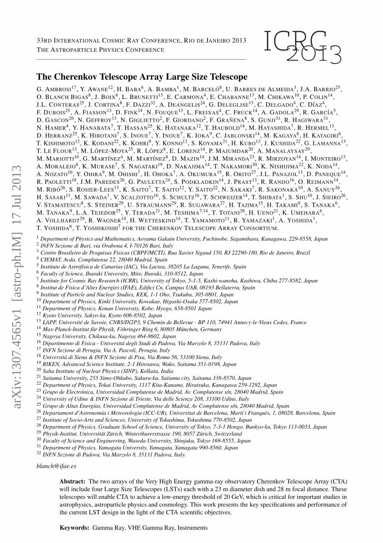
4.1 Camera mechanics and cooling systemThe camera mechanical structure [4] requirements are de-fined by the environmental working conditions, the speci-fications on the required environmental conditions insidethe camera, and on the positioning requirements of the cam-era pixels. Moreover, a strong constraint comes from thestructure of the LST which requires that the total cameraweight not exceed 2000 kg. It is attached to the mast framestructure using a rails system, which allows to modify thecamera position with respect to the mirror, and to unloadit for maintenance. In order to protect the photomultipli-ers and allow operations during daylight with high voltageswitched on, a motorized shutter completely closes the en-trance of light from the front of the camera when required(see figure 4).
ICRC 2013 Template33RD INTERNATIONAL COSMIC RAY CONFERENCE, RIO DE JANEIRO 2013
Figure 4: External view of LST camera design,
The power dissipation of the electronics inside the cam-era can reach 5kW, which results in a considerable amountof heat that has to be taken out from the camera body inorder to keep all elements within their working range in sta-ble temperature conditions. Two different cooling systemshave been considered and are being studied: a temperaturecontrolled air flow cooling system, and a water cooling sys-tem based on cold plates[4].
4.2 Focal Plane InstrumentationA photodetector module consists of a light guide, photomul-tiplier, Cockcroft Walton high voltage power supply andpreamplifier. These components make a module and workas a pixel on the focal plane.
The photo-detector modules are mounted with 50 mmspacing, while the sensitive area of the photomultiplier cath-ode is a circular area with a diameter of 30 mm. Thereforea light guide is essential to collect all Cherenkov light fo-cused on the camera plane. The entrance window of thelight guide is a regular hexagon with the size of 50 mm inflat to flat. The shape of the light guide and the reflectivematerial, 3M ESR film, are optimized to get the maximumefficiency up to 26.7 degrees, the maximum incidence anglegiven the F/D of the mirror and eld of view of the camera.
Hamamatsu R11920-100-20 is the photomultiplier devel-oped for the CTA project. This PMT has 8 Dynodes, a 40mm diameter window, and a Super Bialkali Cathode witha radius of curvature of 21 mm. Frosted entrance glass isused for the PMT surface window. These photomultiplierswere developed aiming at large Quantum Efficiency andlow after pulse rates. The former reaches values of 47% andthe latter goes below 0.02 % above 4 phe. The Cockcroft-Walton is also provided by Hamamatsu and can supply highvoltage from 850 V to 1500 V.
Finally, the signal goes through PACTA, developed byCTA-Spain, before reaching the cluster electronics. PACTAis a wide dynamic range preamplifier with low powerconsumption and low noise.
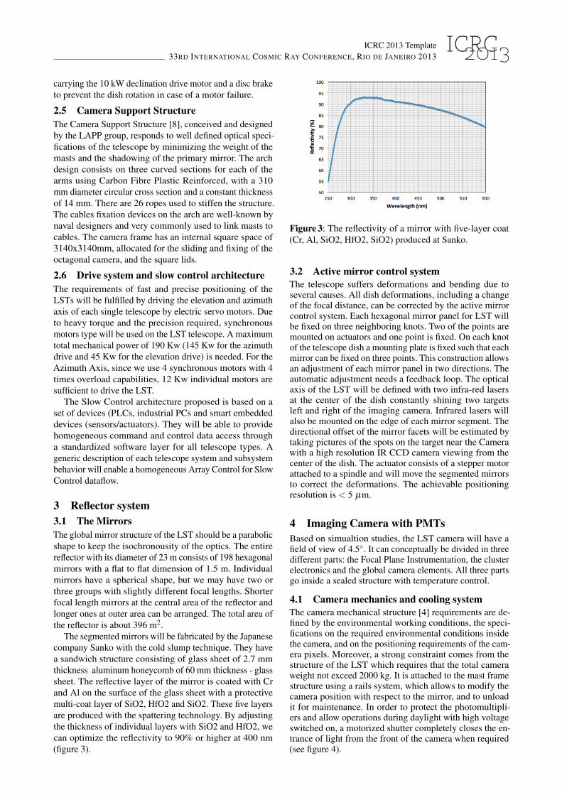
Figure 5: Three clusters including the photodetector mod-ules and electronics.
In order to fulfill the accessibility and weight require-ments, the camera body relies on a simple structural ele-ment, or load bearing structure, which provides the nec-essary stiffness and positioning accuracy for the photo-detectors, and holds all the camera elements.
4.3 Cluster electronicsThe photodetector modules are arranged on the focal planeof each telescope, with one readout system per 7-modulescluster [5] (figure 5). The readout system developed byCTA-Japan is based on the analogue memory DRS version4 (DRS4) [6]. On the readout board the signal is dividedinto three lines: a high gain channel, a low gain channel,and a trigger channel. The high and low gain channels areconnected to DRS4 chips. The signal is sampled at a rate ofthe order of GHz and the waveform is stored in the analoguememory. When a trigger is generated, the voltages stored inthe capacitor array are sequentially output and then digitizedby an external slow sampling ( 30 MHz) ADC.
Although several hardware developments are being de-veloped and will be tested with several clusters, the simula-tions show a superior performance of the Sum Trigger con-cept [7] at the lowest energies, which are the most criticalfor the LST. Hence, the implementation of the Sum Triggerconcept done by CTA-Spain is the baseline option[8].
Acknowledgment:We gratefully acknowledge financial sup-port from the agencies and organisations listed in this page:http://www.cta-observatory.org/?q=node/22.
References[1] http://www.cta-observatory.org/[2] http://magic.mppmu.mpg.de/index.en.html[3] G. Lamanna et al, contribution 535 these proceedings.[4] C. Delgado et al, contribution 371 these proceedings.[5] H. Kubo et al, contribution 206 these proceedings.[6] S. Ritt, R. Dinapoli and U. Hartmann, NIMA 623 (2010)
486-488 doi: 10.1016/j.nima.2010.03.045[7] M. Rissi, N. Otte, T. Schweizer and M. Shayduk, NSS’08
IEEE (2008) 1472 doi: 10.1109/NSSMIC.2008.4774693[8] M. Barcelo et al, contribution 396 these proceedings.