The changes to IEC 61508/Edition 2 implications for users ... · The changes to IEC 61508/Edition 2...
68
© Engineering Safety Consultants Limited Page 1 The changes to IEC 61508/Edition 2 & implications for users of the standard Ron Bell Engineering Safety Consultants Ltd [email protected] www.esc.uk.net
Transcript of The changes to IEC 61508/Edition 2 implications for users ... · The changes to IEC 61508/Edition 2...

© Engineering Safety Consultants Limited Page 1
The changes to IEC 61508/Edition 2
&
implications for users of the standard
Ron BellEngineering Safety Consultants Ltd
© Engineering Safety Consultants Limited Page 2
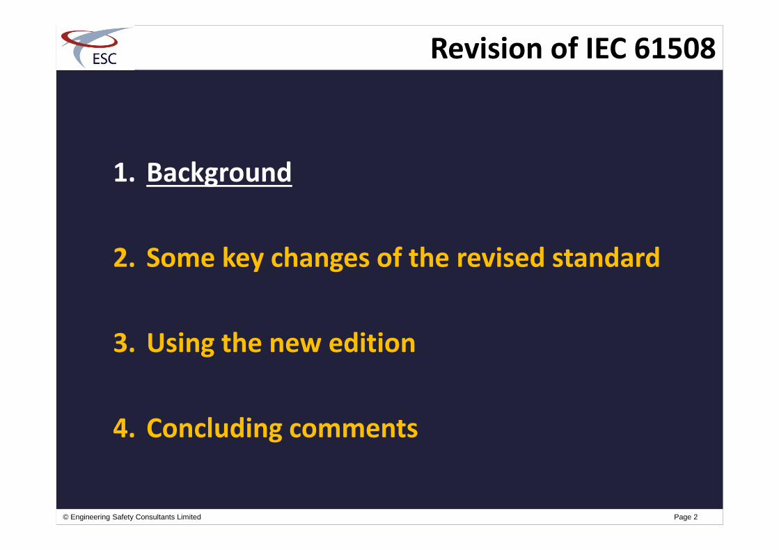
Revision of IEC 61508
1. Background
2. Some key changes of the revised standard
3. Using the new edition
4. Concluding comments

IEC 61508: Brief history
I985: Task Group set up to assess viability ofdeveloping a generic standard on PES’s
Two working groups collaborated on development ofIEC standard that was to become IEC 61508
1998 – 2000: The parts of IEC 61508 (1/2/3/4/5/6/7)Edition 1 were published
2005: PD IEC TR 61508-0 was published
“ENs” adopted in same year as the IEC publicationdates
2003: Revision of IEC 61508 / Edition started
2010: IEC 61508 / Edition 2 was published in April
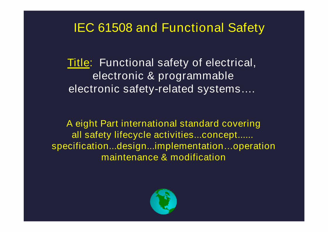
IEC 61508 and Functional Safety
Title: Functional safety of electrical,electronic & programmable
electronic safety-related systems….
A eight Part international standard coveringall safety lifecycle activities...concept......
specification...design...implementation…operationmaintenance & modification
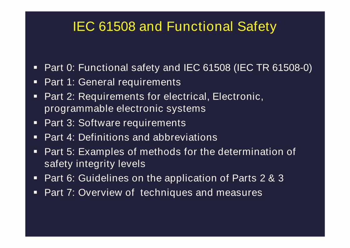
Part 0: Functional safety and IEC 61508 (IEC TR 61508-0)
Part 1: General requirements
Part 2: Requirements for electrical, Electronic,programmable electronic systems
Part 3: Software requirements
Part 4: Definitions and abbreviations
Part 5: Examples of methods for the determination ofsafety integrity levels
Part 6: Guidelines on the application of Parts 2 & 3
Part 7: Overview of techniques and measures
IEC 61508 and Functional Safety

IEC 61508 and Functional Safety
Part 0: Functional safety and IEC 61508 (IEC TR 61508-0)
Part 1: General requirements
Part 2: Requirements for electrical, Electronic, programmableelectronic systems
Part 3: Software requirements
Part 4: Definitions and abbreviations
Part 5: Examples of methods for the determination of safety integritylevels
Part 6: Guidelines on the application of Parts 2 & 3
Part 7: Overview of techniques and measures
Parts 1, 2 & 3 contain normative & informative requirements
Parts 0, 5, 6 & 7 contain only informative requirements
A “shall” is a normative requirement
A “should” is an informative requirement
Notes are informative
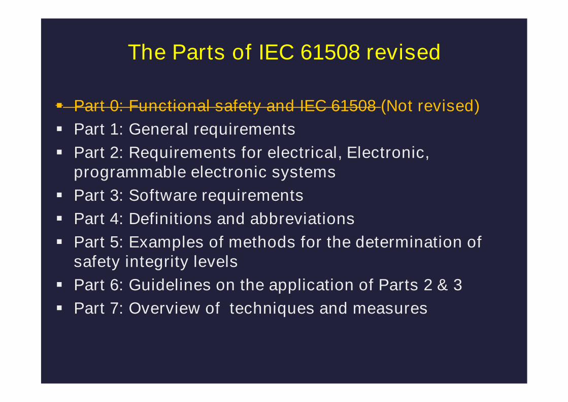
Part 0: Functional safety and IEC 61508 (Not revised)
Part 1: General requirements
Part 2: Requirements for electrical, Electronic,programmable electronic systems
Part 3: Software requirements
Part 4: Definitions and abbreviations
Part 5: Examples of methods for the determination ofsafety integrity levels
Part 6: Guidelines on the application of Parts 2 & 3
Part 7: Overview of techniques and measures
The Parts of IEC 61508 revised

© Engineering Safety Consultants Limited Page 8
Revision of IEC 61508
1. Background
2. Some key changes of the revised standard
3. Using the new edition
4. Concluding comments

© Engineering Safety Consultants Limited Page 9
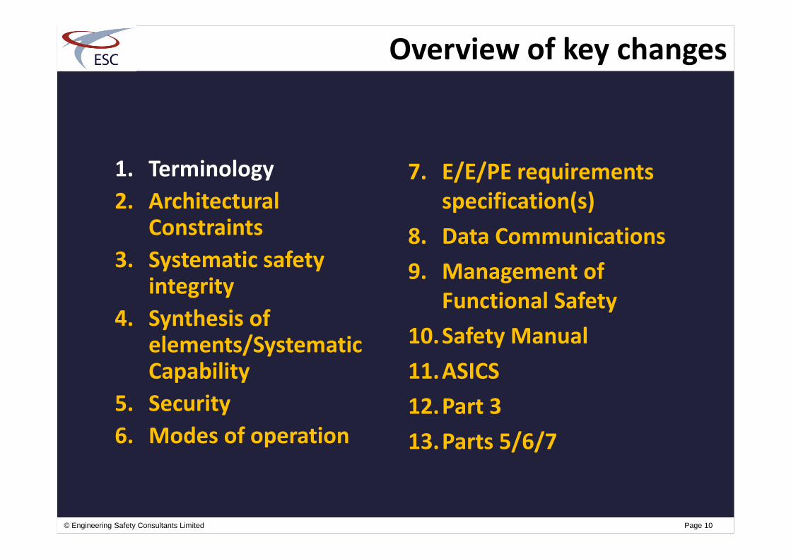
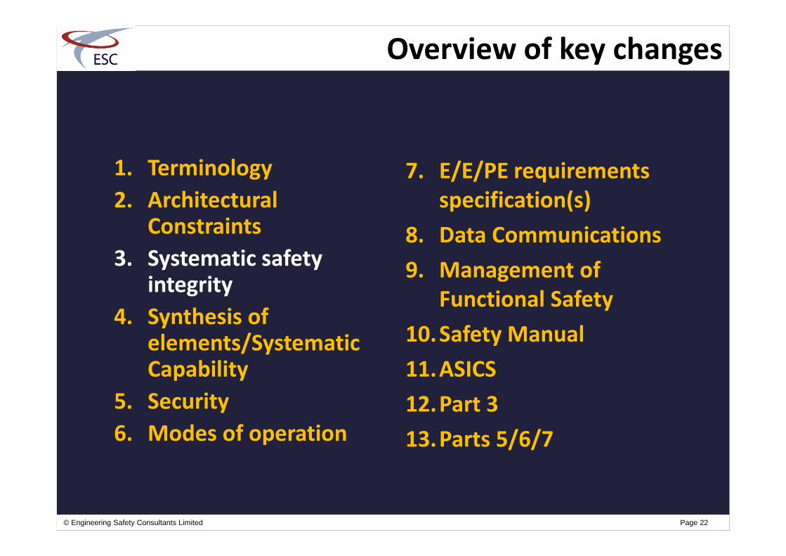
Overview of key changes
1. Terminology
2. ArchitecturalConstraints
3. Systematic safetyintegrity
4. Synthesis ofelements/SystematicCapability
5. Security
6. Modes of operation
7. E/E/PE requirementsspecification(s)
8. Data Communications
9. Management ofFunctional Safety
10.Safety Manual
11.ASICS
12.Part 3
13.Parts 5/6/7
© Engineering Safety Consultants Limited Page 10
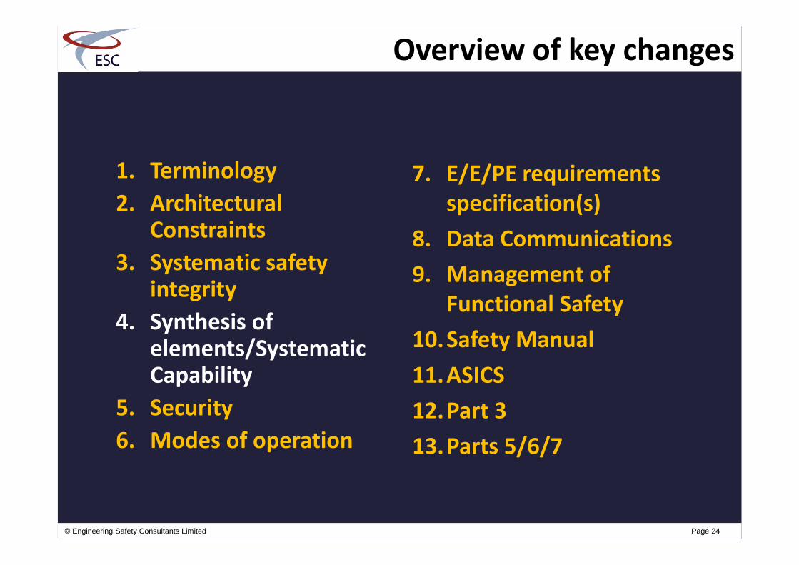
Overview of key changes
1. Terminology
2. ArchitecturalConstraints
3. Systematic safetyintegrity
4. Synthesis ofelements/SystematicCapability
5. Security
6. Modes of operation
7. E/E/PE requirementsspecification(s)
8. Data Communications
9. Management ofFunctional Safety
10.Safety Manual
11.ASICS
12.Part 3
13.Parts 5/6/7
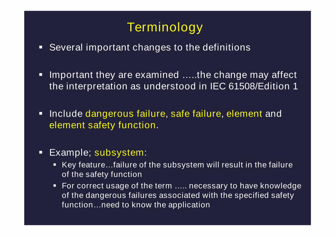
Terminology
Several important changes to the definitions
Important they are examined …..the change may affectthe interpretation as understood in IEC 61508/Edition 1
Include dangerous failure, safe failure, element andelement safety function.
Example; subsystem: Key feature…failure of the subsystem will result in the failure
of the safety function
For correct usage of the term ….. necessary to have knowledgeof the dangerous failures associated with the specified safetyfunction…need to know the application

Terminology: System & Subsystem
ControllerSensors Final elements
subsystems
Failure of the subsystem will resultin the failure of the safety function
system
elements

© Engineering Safety Consultants Limited Page 13
Overview of key changes
1. Terminology
2. ArchitecturalConstraints
3. Systematic safetyintegrity
4. Synthesis ofelements/SystematicCapability
5. Security
6. Modes of operation
7. E/E/PE requirementsspecification(s)
8. Data Communications
9. Management ofFunctional Safety
10.Safety Manual
11.ASICS
12.Part 3
13.Parts 5/6/7

Route 1H: based on hardware fault tolerance andsafe failure fraction concepts; or,
Route 2H: based on component reliability datafrom feedback from end users, increasedconfidence levels and hardware fault tolerance forspecified safety integrity levels.
Route 1H: based on hardware fault tolerance andsafe failure fraction concepts; or,
Route 2H: based on component reliability datafrom feedback from end users, increasedconfidence levels and hardware fault tolerance forspecified safety integrity levels.
Architectural Constraints
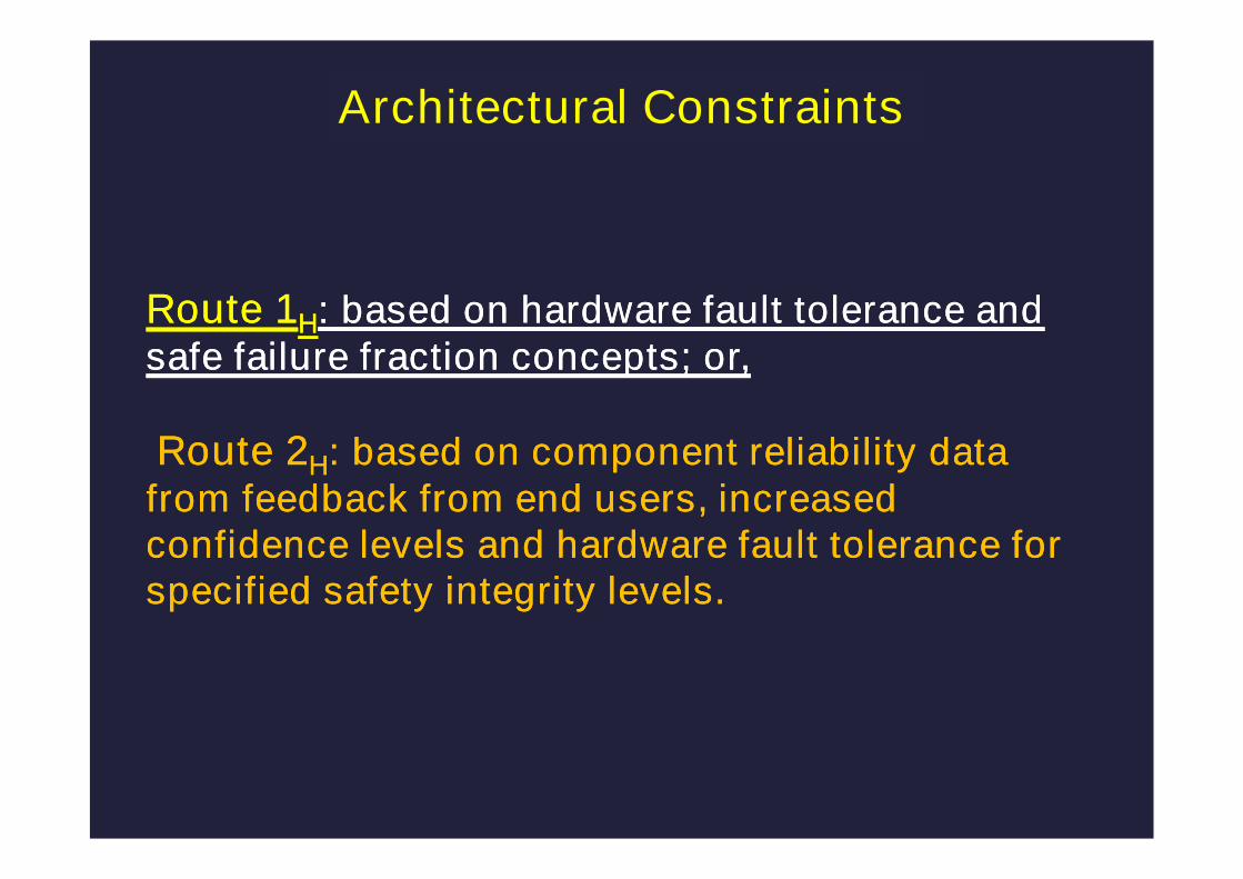
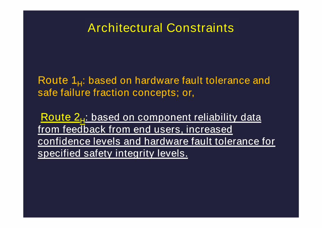
Route 1H: based on hardware fault tolerance andsafe failure fraction concepts; or,
Route 2H: based on component reliability datafrom feedback from end users, increasedconfidence levels and hardware fault tolerance forspecified safety integrity levels.
Route 1H: based on hardware fault tolerance andsafe failure fraction concepts; or,
Route 2H: based on component reliability datafrom feedback from end users, increasedconfidence levels and hardware fault tolerance forspecified safety integrity levels.
Architectural Constraints

Architectural 1H: Constraints Route 1H
Based on hardware fault tolerance and safefailure fraction concepts;
Some changes made to the method of calculatingthe maximum SIL that can be claimed;
new definitions of safe & dangerous failures willalso have an impact on maximum SIL that can beclaimed;
Important the clauses are read before applyingthe Tables!
Route 1H: based on hardware fault tolerance andsafe failure fraction concepts; or,
Route 2H: based on component reliability datafrom feedback from end users, increasedconfidence levels and hardware fault tolerance forspecified safety integrity levels.
Route 1H: based on hardware fault tolerance andsafe failure fraction concepts; or,
Route 2H: based on component reliability datafrom feedback from end users, increasedconfidence levels and hardware fault tolerance forspecified safety integrity levels.
Architectural Constraints

A hardware fault tolerance of 2 for a specified safety function ofSIL 4 unless the conditions in clause 7.4.4.3.2 apply.
A hardware fault tolerance of 1 for a specified safety function ofSIL 3 unless the conditions in clause 7.4.4.3.2 apply.
A hardware fault tolerance of 1 for a specified safety function ofSIL 2, operating in a high demand or continuous mode ofoperation, unless the conditions in clause 7.4.4.3.2 apply.
A hardware fault tolerance of 0 for a specified safety function ofSIL 2 operating in a low demand mode of operation.
A hardware fault tolerance of 0 for a specified safety function ofSIL 1.
Architectural Constraints: Route 2H
IEC 61508-2: Clause 7.4.4.3.1

For Type A elements only: HFT can be reduced to thosespecified in 7.4.4.3.1 providing there is evidence that:
by following the requirements in 7.4.4.3.1 would introduceadditional failures and would lead to a decrease in overall safetyof the EUC; and
if HFT is reduced to zero the failure modes, in the elementcarrying out the safety function, can be excluded because theassociated dangerous failure rates are very low compared to thetarget failure measure for the safety function
A note to 7.4.4.3.2 indicates that fault tolerance is the preferredsolution
Architectural Constraints: Route 2H
IEC 61508-2: Clause 7.4.4.3.2
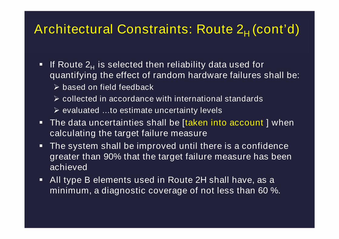
If Route 2H is selected then reliability data used forquantifying the effect of random hardware failures shall be:
based on field feedback
collected in accordance with international standards
evaluated …to estimate uncertainty levels
The data uncertainties shall be [taken into account ] whencalculating the target failure measure
The system shall be improved until there is a confidencegreater than 90% that the target failure measure has beenachieved
All type B elements used in Route 2H shall have, as aminimum, a diagnostic coverage of not less than 60 %.
Architectural Constraints: Route 2H (cont’d)
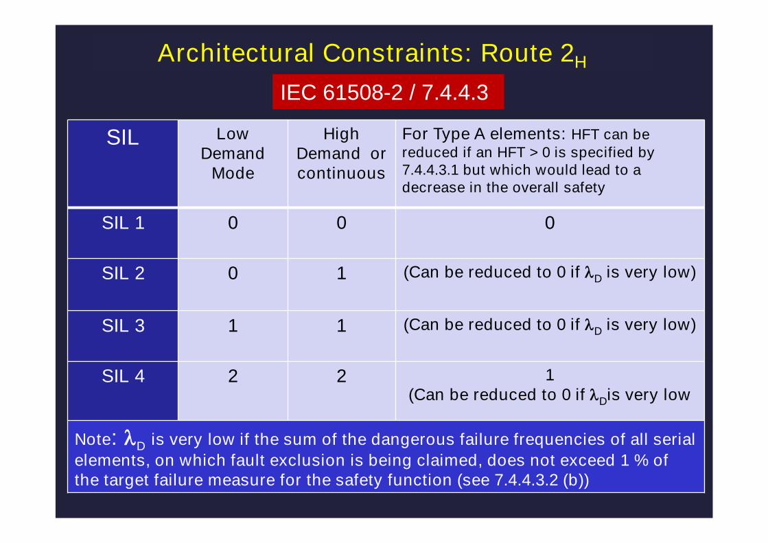
Architectural Constraints: Route 2H
SIL LowDemand
Mode
HighDemand orcontinuous
For Type A elements: HFT can bereduced if an HFT > 0 is specified by7.4.4.3.1 but which would lead to adecrease in the overall safety
SIL 1 0 0 0
SIL 2 0 1 (Can be reduced to 0 if lD is very low)
SIL 3 1 1 (Can be reduced to 0 if lD is very low)
SIL 4 2 2 1(Can be reduced to 0 if lDis very low
Note: lD is very low if the sum of the dangerous failure frequencies of all serial
elements, on which fault exclusion is being claimed, does not exceed 1 % ofthe target failure measure for the safety function (see 7.4.4.3.2 (b))
IEC 61508-2 / 7.4.4.3
© Engineering Safety Consultants Limited Page 22
Overview of key changes
1. Terminology
2. ArchitecturalConstraints
3. Systematic safetyintegrity
4. Synthesis ofelements/SystematicCapability
5. Security
6. Modes of operation
7. E/E/PE requirementsspecification(s)
8. Data Communications
9. Management ofFunctional Safety
10.Safety Manual
11.ASICS
12.Part 3
13.Parts 5/6/7
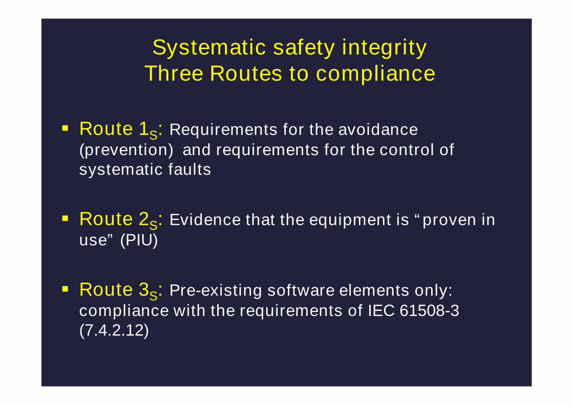
Systematic safety integrityThree Routes to compliance
Route 1S: Requirements for the avoidance(prevention) and requirements for the control ofsystematic faults
Route 2S: Evidence that the equipment is “proven inuse” (PIU)
Route 3S: Pre-existing software elements only:compliance with the requirements of IEC 61508-3(7.4.2.12)
© Engineering Safety Consultants Limited Page 24
Overview of key changes
1. Terminology
2. ArchitecturalConstraints
3. Systematic safetyintegrity
4. Synthesis ofelements/SystematicCapability
5. Security
6. Modes of operation
7. E/E/PE requirementsspecification(s)
8. Data Communications
9. Management ofFunctional Safety
10.Safety Manual
11.ASICS
12.Part 3
13.Parts 5/6/7

Measure (expressed on a scale of SC 1 to SC 4) of the
confidence that the systematic safety integrity of an
element meets the requirements of the specified SIL,
in respect of the specified element safety function…
Systematic Capability
Revision of IEC 61508: Overview
The concept of Systematic Capability is new to IEC 61508/Edition 2

IEC 61508-2: 7.4.3: Synthesis of elements toachieve the required systematic capability
A systematic fault of element 1 does not cause a failure of thespecified safety function but does so only in combination with asecond systematic fault of element 2
Elements 1 & 2 sufficiently independent of each other
SC 1
SC 1
1
2

IEC 61508-2: 7.4.3: Synthesis of elements toachieve the required systematic capability
SC 23
A systematic fault of element 1 does not cause a failure of thespecified safety function but does so only in combination with asecond systematic fault of element 2
Elements 1 & 2 sufficiently independent of each other
The combination of elements 1 & 2 leads to systematic capabilityof SC 2
SC 1
SC 1
1
2

Simplified Example:Systematic Safety Integrity / Systematic Capability
System limited to SIL 1 for specified safety function
ControllerSensors Final elements
SC 3SC 2
SC 2
SC 1
SC 1
SC 2 SC 1
SC 2 SC 3 SC 1
SC 1IEC 61508/Edition 1

System limited to SIL 1 for specified safety function
ControllerSensors Final elements
SC 3SC 2
SC 2
SC 1
SC 1
SC 2 SC 1
SC 2 SC 3 SC 1
SC 1
Sensors & Final elementsnot sufficientlyindependent!
IEC 61508/Edition 2
Simplified Example:Systematic Safety Integrity / Systematic Capability

System limited to SIL 2 for specified safety function
ControllerSensors Final elements
SC 3SC 2
SC 2
SC 1
SC 1
SC 3 SC 2
SC 3 SC 3 SC 2
SC 2
Sensors & Final elementssufficiently independent!
IEC 61508/Edition 2
Simplified Example:Systematic Safety Integrity / Systematic Capability
© Engineering Safety Consultants Limited Page 31
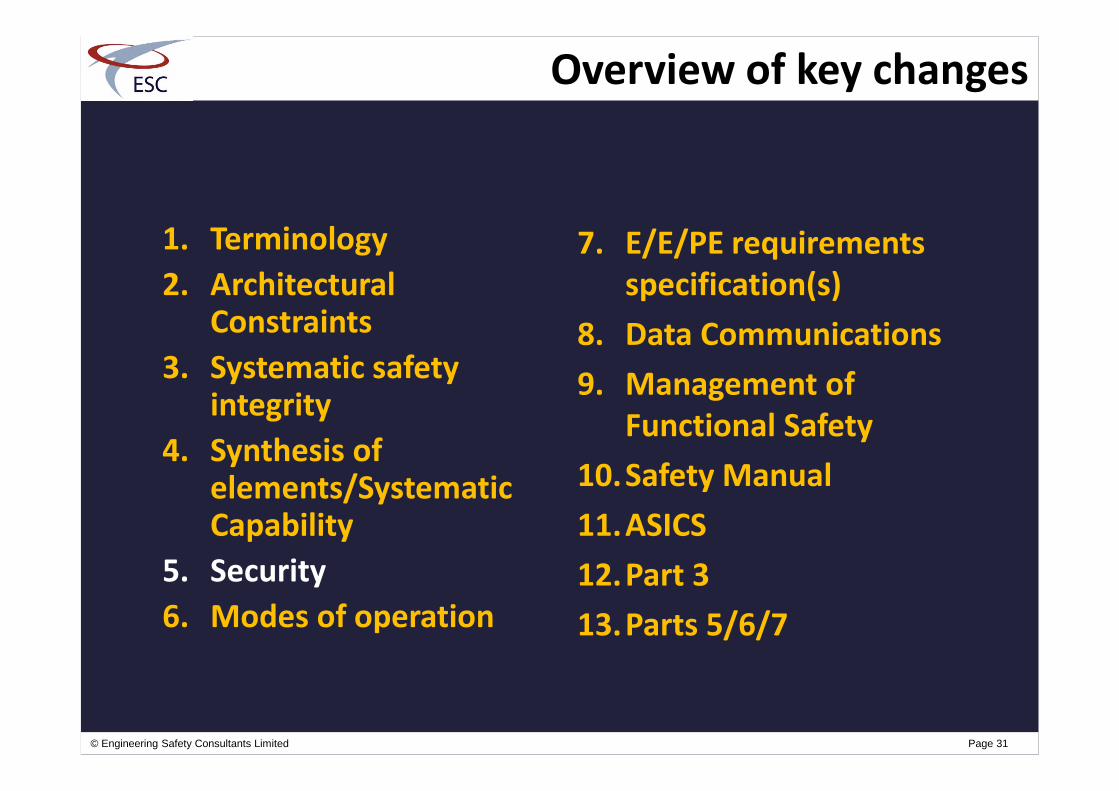
Overview of key changes
1. Terminology
2. ArchitecturalConstraints
3. Systematic safetyintegrity
4. Synthesis ofelements/SystematicCapability
5. Security
6. Modes of operation
7. E/E/PE requirementsspecification(s)
8. Data Communications
9. Management ofFunctional Safety
10.Safety Manual
11.ASICS
12.Part 3
13.Parts 5/6/7

Requires malevolent and unauthorised actions to beaddressed during hazard and risk analysis. If securitythreat is seen as being reasonably foreseeable, then:
a security threats analysis should be carried out
if security threats have been identified then avulnerability analysis should be undertaken in order tospecify security requirements.
Rationale for the policy: Other IEC/ISO standards will be referencedthat address this subject in depth
Security aspects
© Engineering Safety Consultants Limited Page 33
Overview of key changes
1. Terminology
2. ArchitecturalConstraints
3. Systematic safetyintegrity
4. Synthesis ofelements/SystematicCapability
5. Security
6. Modes of operation
7. E/E/PE requirementsspecification(s)
8. Data Communications
9. Management ofFunctional Safety
10.Safety Manual
11.ASICS
12.Part 3
13.Parts 5/6/7

34
SafetyIntegrity
Level(SIL)
1
2
3
4
Low demand modeof operation
High demand/continuousmode of operation
Average probabilityof failure/demand
Dangerous failure rate[per hour]
Target Failure Measures for a safety function allocated to anE/E/PE safety-related system
See IEC 61508-4; 3.5.12
Low demand mode:Where the frequency ofdemands for operationmade on an SRS is nogreater than:• one per year; and,• no greater than twice theproof-test frequency
See IEC 61508-4; 3.5.12
High demand/continuousmode:Where the frequency ofdemands for operationmade on an SRS is greaterthan:• one per year; or,• greater than twice theproof-test frequency
Target Failure Measures: Edition 1

35
SafetyIntegrity
Level(SIL)
1
2
3
4
Low demand modeof operation
High demand/continuousmode of operation
Average probabilityof failure/demand
Dangerous failure rate[per hour]
Target Failure Measures for a safety function allocated to anE/E/PE safety-related system
See IEC 61508-4; 3.5.12
Low demand mode:Where the frequency ofdemands for operationmade on an SRS is nogreater than:• one per year; and,• no greater than twice theproof-test frequency
See IEC 61508-4; 3.5.12
High demand/continuousmode:Where the frequency ofdemands for operationmade on an SRS is greaterthan:• one per year; or,• greater than twice theproof-test frequency
Target Failure Measures: Edition 2
© Engineering Safety Consultants Limited Page 36
Overview of key changes
1. Terminology
2. ArchitecturalConstraints
3. Systematic safetyintegrity
4. Synthesis ofelements/SystematicCapability
5. Security
6. Modes of operation
7. E/E/PE requirementsspecification(s)
8. Data Communications
9. Management ofFunctional Safety
10.Safety Manual
11.ASICS
12.Part 3
13.Parts 5/6/7
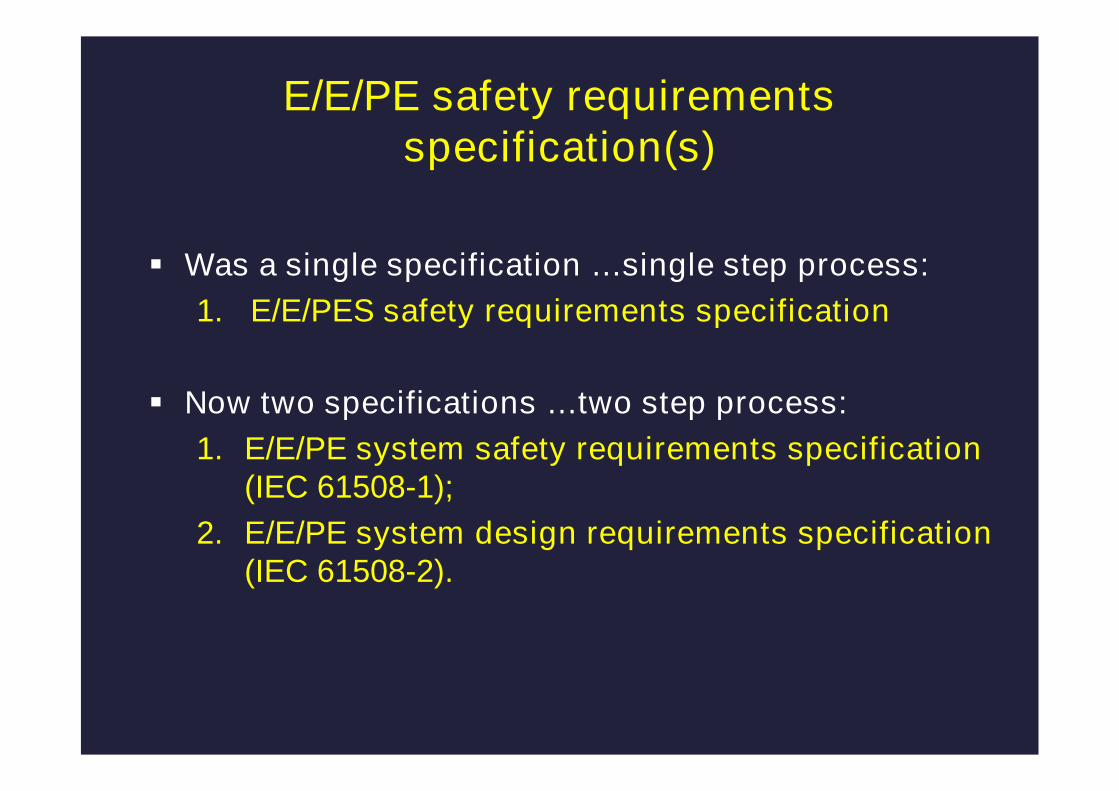
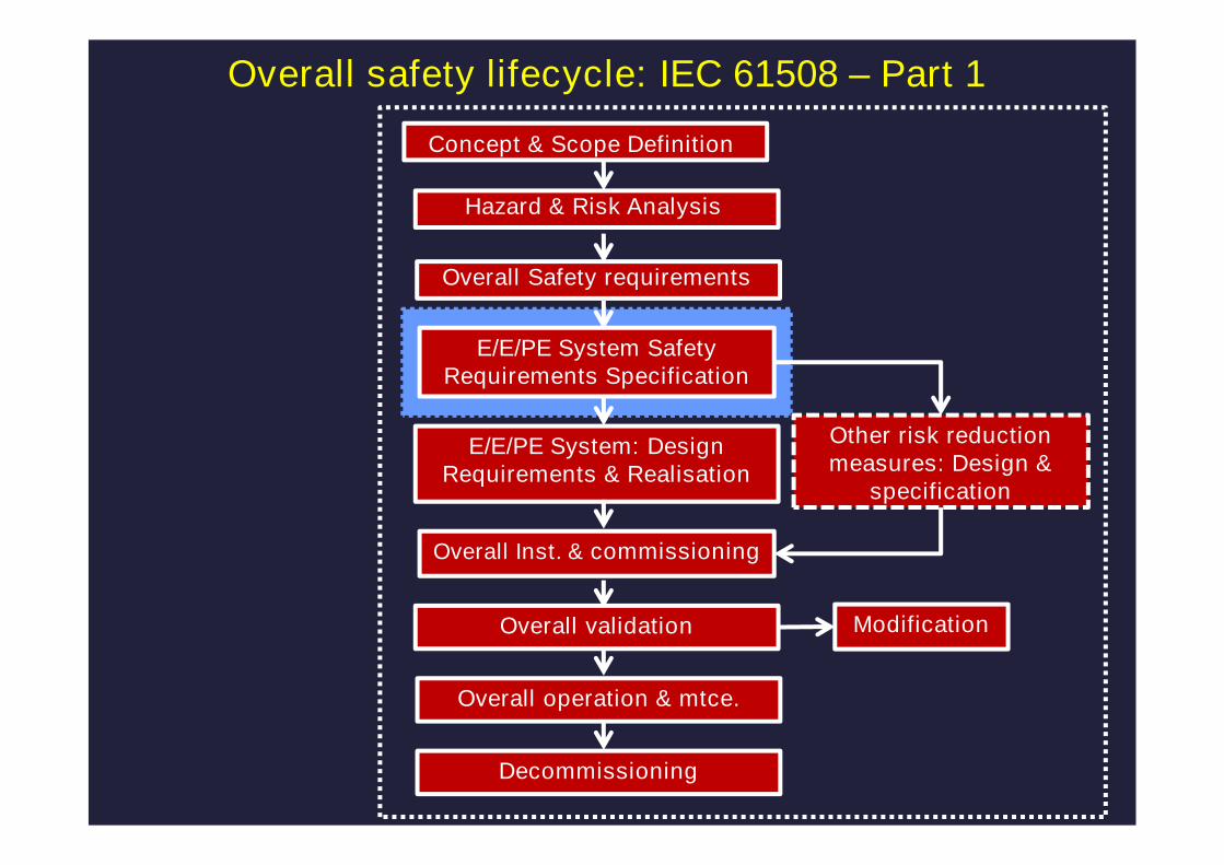
E/E/PE safety requirementsspecification(s)
Was a single specification …single step process:
1. E/E/PES safety requirements specification
Now two specifications …two step process:
1. E/E/PE system safety requirements specification(IEC 61508-1);
2. E/E/PE system design requirements specification(IEC 61508-2).
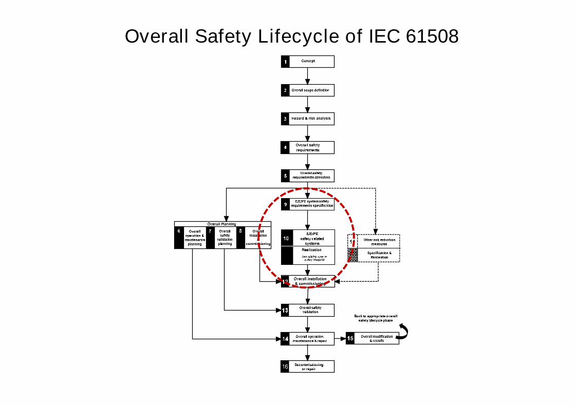
Overall Safety Lifecycle of IEC 61508
Other risk reductionmeasures: Design &
specification
E/E/PE System: DesignRequirements & Realisation
Overall validation
Overall operation & mtce.
Decommissioning
Hazard & Risk Analysis
Concept & Scope Definition
Modification
E/E/PE System SafetyRequirements Specification
Overall Safety requirements
Overall Inst. & commissioning
Overall safety lifecycle: IEC 61508 – Part 1

Other risk reductionmeasures: Design &
specification
E/E/PE System: DesignRequirements & Realisation
Overall safety lifecycle: IEC 61508 – Part 1
Overall validation
Overall operation & mtce.
Decommissioning
Hazard & Risk Analysis
Concept & Scope Definition
E/E/PE System SafetyRequirements Specification
Overall Safety requirements
Overall Inst. & commissioning
IEC 61508-2
Modification
© Engineering Safety Consultants Limited Page 41
Overview of key changes
1. Terminology
2. ArchitecturalConstraints
3. Systematic safetyintegrity
4. Synthesis ofelements/SystematicCapability
5. Security
6. Modes of operation
7. E/E/PE requirementsspecification(s)
8. Data Communications
9. Management ofFunctional Safety
10.Safety Manual
11.ASICS
12.Part 3
13.Parts 5/6/7
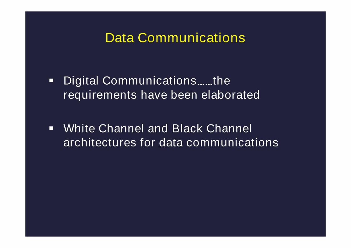
Data Communications
Digital Communications……therequirements have been elaborated
White Channel and Black Channelarchitectures for data communications

© Engineering Safety Consultants Limited Page 43
Data Communications
Entire communication channel (including protocol, services & network components)comply with IEC 61508 & (IEC 61784-3 or IEC 62280)
WHITE CHANNEL
Element complieswith IEC 61508
Element complieswith IEC 61508
Subsystem/element complies
with IEC 61508
Subsystem/element complies
with IEC 61508
BLACK CHANNEL
Parts of the communication channelbetween the interfaces are not
designed or validated to IEC 61508
Interfaces comply with IEC 61784-3 or IEC 62280 (including services & protocols)
Element complieswith IEC 61508
Element complieswith IEC 61508
Subsystem/element complies
with IEC 61508
Subsystem/element complies
with IEC 61508

Data Communications
IEC 61784-3: Industrial communication networks -Profiles – Part 3: Functional safety fieldbuses -General rules and profile definition
IEC 62280: Railway applications -Communication, signalling and processingsystems - Part 2: Safety-related communication inopen transmission systems
© Engineering Safety Consultants Limited Page 45
Overview of key changes
1. Terminology
2. ArchitecturalConstraints
3. Systematic safetyintegrity
4. Synthesis ofelements/SystematicCapability
5. Security
6. Modes of operation
7. E/E/PE requirementsspecification(s)
8. Data Communications
9. Management ofFunctional Safety
10.Safety Manual
11.ASICS
12.Part 3
13.Parts 5/6/7

Other risk reductionmeasures: Design &
specification
E/E/PE System: DesignRequirements & Realisation
Overall safety lifecycle: IEC 61508
Man
ag
em
en
to
ffu
ncti
on
alsafe
ty(i
nclu
din
gco
mp
ete
nce)
Fu
ncti
on
alS
afe
tyA
sse
ssm
en
t
Overall validation
Overall operation & mtce.
Decommissioning
Veri
ficati
on
Hazard & Risk Analysis
Concept & Scope Definition
E/E/PE System SafetyRequirements Specification
Overall Safety requirements
Overall Inst. & commissioning
Modification
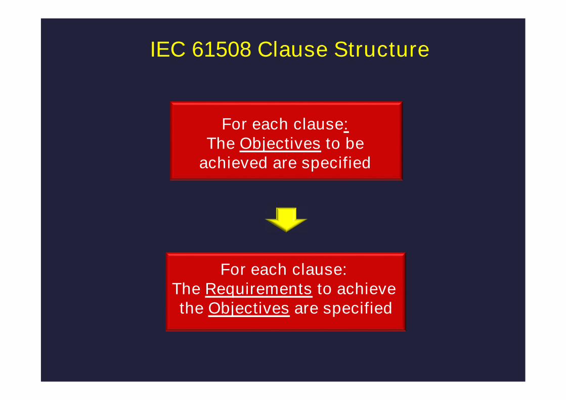
IEC 61508 Clause Structure
For each clause:The Requirements to achievethe Objectives are specified
For each clause:The Objectives to be
achieved are specified
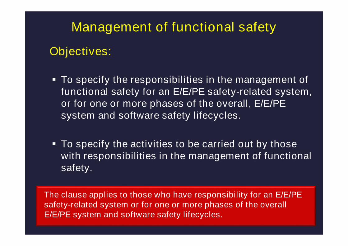
Management of functional safety
Objectives:
To specify the responsibilities in the management offunctional safety for an E/E/PE safety-related system,or for one or more phases of the overall, E/E/PEsystem and software safety lifecycles.
To specify the activities to be carried out by thosewith responsibilities in the management of functionalsafety.
The clause applies to those who have responsibility for an E/E/PEsafety-related system or for one or more phases of the overallE/E/PE system and software safety lifecycles.

Management of Functional SafetyIEC 61508-1; Clause 6
Key requirements forthe Management ofFunctional Safety
Suppliers of products etc toresponsible organisation
Management &technical activities
Responsibilities:organisational
& personal
Training & information toemergency services
Procedures to bedeveloped
Functional safetyaudits
Policy & strategyCompetence of
responsible persons

Management of functional safety
Completely restructured….more comprehensivenormative requirements including: Appointment of one or more persons by an organisation with
responsibility for one or more phases……………
Identification of all persons undertaking defined activities
All those persons undertaking defined activities shall becompetent for the duties they have to perform.
The competence of those with defined responsibilities shall bedocumented
Important change …in IEC 61508/Edition 1, the normativerequirement was restricted to the Functional SafetyAssessment activity.

© Engineering Safety Consultants Limited Page 51
Overview of key changes
1. Terminology
2. ArchitecturalConstraints
3. Systematic safetyintegrity
4. Synthesis ofelements/SystematicCapability
5. Security
6. Modes of operation
7. E/E/PE requirementsspecification(s)
8. Data Communications
9. Management ofFunctional Safety
10.Safety Manual
11.ASICS
12.Part 3
13.Parts 5/6/7
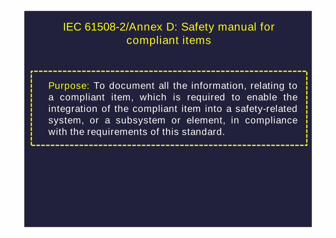
Purpose: To document all the information, relating toa compliant item, which is required to enable theintegration of the compliant item into a safety-relatedsystem, or a subsystem or element, in compliancewith the requirements of this standard.
IEC 61508-2/Annex D: Safety manual forcompliant items

IEC 61508-2/ 7.4.9: Requirements for E/E/PE systemimplementation
7.4.9.6 Suppliers shall provide a safety manual forcompliant items, in accordance with Annex D, for eachcompliant item that they supply and for which they claimcompliance with IEC 61508 series.
7.4.9.7 The supplier shall document a justification for allthe information that is provided in each safety manual forcompliant items.
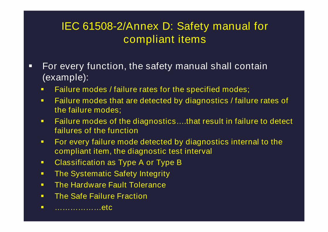
For every function, the safety manual shall contain(example): Failure modes / failure rates for the specified modes;
Failure modes that are detected by diagnostics / failure rates ofthe failure modes;
Failure modes of the diagnostics….that result in failure to detectfailures of the function
For every failure mode detected by diagnostics internal to thecompliant item, the diagnostic test interval
Classification as Type A or Type B
The Systematic Safety Integrity
The Hardware Fault Tolerance
The Safe Failure Fraction
………………etc
IEC 61508-2/Annex D: Safety manual forcompliant items
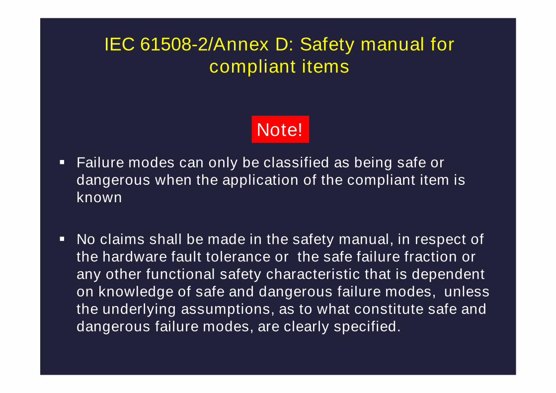
Failure modes can only be classified as being safe ordangerous when the application of the compliant item isknown
No claims shall be made in the safety manual, in respect ofthe hardware fault tolerance or the safe failure fraction orany other functional safety characteristic that is dependenton knowledge of safe and dangerous failure modes, unlessthe underlying assumptions, as to what constitute safe anddangerous failure modes, are clearly specified.
Note!
IEC 61508-2/Annex D: Safety manual forcompliant items
© Engineering Safety Consultants Limited Page 56
Overview of key changes
1. Terminology
2. ArchitecturalConstraints
3. Systematic safetyintegrity
4. Synthesis ofelements/SystematicCapability
5. Security
6. Modes of operation
7. E/E/PE requirementsspecification(s)
8. Data Communications
9. Management ofFunctional Safety
10.Safety Manual
11.ASICS
12.Part 3
13.Parts 5/6/7

ASICS & ICs
An appropriate group of techniques and measuresshall be used that are essential to prevent theintroduction of faults during the design anddevelopment of ASICs
Note: The definition of ASIC covers a range of devicesFPGAs, PLDs…...
Techniques and measures that support theachievement of relevant properties are given ininformative Annex F.
Special architecture requirements for integratedcircuits (ICs) with on-chip redundancy are given innormative Annex E.

© Engineering Safety Consultants Limited Page 58
Overview of key changes
1. Terminology
2. ArchitecturalConstraints
3. Systematic safetyintegrity
4. Synthesis ofelements/SystematicCapability
5. Security
6. Modes of operation
7. E/E/PE requirementsspecification(s)
8. Data Communications
9. Management ofFunctional Safety
10.Safety Manual
11.ASICS
12.Part 3
13.Parts 5/6/7

Software
Properties have been introduced(such as completeness,correctness and predictability) for the output of eachlifecycle phase to assist in the selection of thetechniques & measures
Given the large number of factors that affect softwaresystematic capability it is not possible to give analgorithm for combining the techniques and measuresthat will be correct for any given application.
The purpose of Annex C is: to give guidance on selecting specific techniques from Annexes
A and B to achieve software systematic capability;
to outline a rationale for justifying the use of techniques that arenot explicitly listed in Annexes A and B.

Software
Extended requirements for the selection and justificationof software development tools.
Allowing software elements not originally developedwith safety in mind to be re-used in safety relatedapplications by the provision of suitable evidenceincluding evidence of successful use in otherapplications.
Revision to the set of technique and measures inAnnexes A and B, to remove obsolete or little-usedtechniques and introduce current methods.
© Engineering Safety Consultants Limited Page 61
Overview of key changes
1. Terminology
2. ArchitecturalConstraints
3. Systematic safetyintegrity
4. Synthesis ofelements/SystematicCapability
5. Security
6. Modes of operation
7. E/E/PE requirementsspecification(s)
8. Data Communications
9. Management ofFunctional Safety
10.Safety Manual
11.ASICS
12.Part 3
13.Parts 5/6/7
© Engineering Safety Consultants Limited Page 62
Revision of IEC 61508
1. Background
2. Some key changes of the revised standard
3. Using the new edition
4. Concluding comments
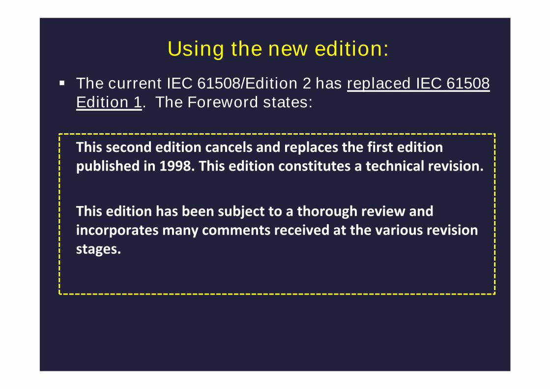
Using the new edition:
The current IEC 61508/Edition 2 has replaced IEC 61508Edition 1. The Foreword states:
This second edition cancels and replaces the first editionpublished in 1998. This edition constitutes a technical revision.
This edition has been subject to a thorough review andincorporates many comments received at the various revisionstages.

Using the new edition
New projects: Taking into account the to paragraph in the Foreword it
would be sensible to use IEC 61508/Edition 2 for newprojects
Existing systems:
There are no specified rules for conformance requirementsfor systems comprising elements conforming to IEC61508/Edition 1 and elements conforming to IEC61508/Edition 2. Is this an issue?
Migration to the new edition: With respect to health and safety legislation the concept of
“reasonable practicability” applies and that would need tobe taken into account in the decision-making process.
© Engineering Safety Consultants Limited Page 65
Revision of IEC 61508
1. Background
2. Some key changes of the revised standard
3. Using the new edition
4. Concluding comments
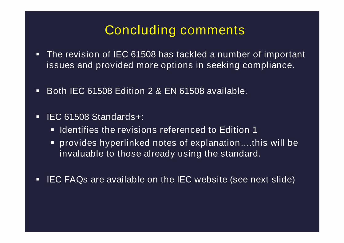
Concluding comments
The revision of IEC 61508 has tackled a number of importantissues and provided more options in seeking compliance.
Both IEC 61508 Edition 2 & EN 61508 available.
IEC 61508 Standards+:
Identifies the revisions referenced to Edition 1
provides hyperlinked notes of explanation….this will beinvaluable to those already using the standard.
IEC FAQs are available on the IEC website (see next slide)
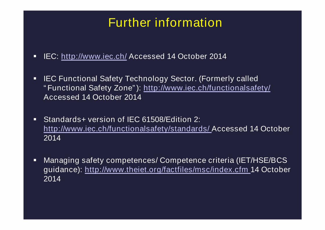
Further information
IEC: http://www.iec.ch/ Accessed 14 October 2014
IEC Functional Safety Technology Sector. (Formerly called“Functional Safety Zone”): http://www.iec.ch/functionalsafety/Accessed 14 October 2014
Standards+ version of IEC 61508/Edition 2:http://www.iec.ch/functionalsafety/standards/ Accessed 14 October2014
Managing safety competences/ Competence criteria (IET/HSE/BCSguidance): http://www.theiet.org/factfiles/msc/index.cfm 14 October2014
The changes to IEC 61508/Edition 2
&
implications for users of the standard
Thank you
Version 14 10 2014


![Comparison of software safety standards IEC 61508 …...specifically targets selected IEC I&C software safety standards IEC 61508-3 [8] and IEC 62138, which are introduced more extensively](https://static.fdocuments.us/doc/165x107/5ede2b4fad6a402d6669785a/comparison-of-software-safety-standards-iec-61508-specifically-targets-selected.jpg)