The Challenges of mmWave Measurements - Cambridge Wireless€¦ · 802.11ad • Allows devices to...
34
Image Size W195 x H530 px The Challenges of mmWave Measurements Paul Holes RFuWave Field Applications Engineer Engineering & Technology Group Anritsu EMEA Ltd May 2019
Transcript of The Challenges of mmWave Measurements - Cambridge Wireless€¦ · 802.11ad • Allows devices to...

Image SizeW195 x H530 px
The Challenges of mmWaveMeasurements
Paul HolesRFuWave Field Applications EngineerEngineering & Technology Group Anritsu EMEA Ltd
May 2019

2 Copyright© ANRITSU
Agenda
• The mmWave boom
• mmWave applications
• Challenges of mmWave measurements
• Addressing the challenges
• New, innovative solutions
3 Copyright© ANRITSU
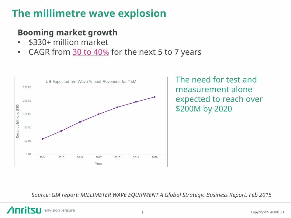
The millimetre wave explosion
Booming market growth• $330+ million market• CAGR from 30 to 40% for the next 5 to 7 years
The need for test and measurement alone expected to reach over $200M by 2020
Source: GIA report: MILLIMETER WAVE EQUIPMENT A Global Strategic Business Report, Feb 2015

4 Copyright© ANRITSU
Why mmWave?
UNLICENSED SPECTRUM
More available bandwidth
Higher data rates

5 Copyright© ANRITSU
What’s driving the boom?
➢ 5G: 28, 39, 60 GHz
➢ Microwave Radios: 70/80 GHz, 90 GHz
➢ IEEE 802.11ad (WiGig): 57 - 66 GHz
➢ Automotive Radar: 76 - 81 GHz
➢ Satellite: 27 - 40 GHz (Ka band), 40 - 75 GHz, (V band)
➢ SRW and ISM Devices: 45, 60, 75, 92 GHz
➢ TSCM: Any frequency

6 Copyright© ANRITSU
• Demand for mobile data spectrum keeps growing• Increasing number of smart phone users• Users finding new applications that require
very high data rates. • 5G is still evolving but it appears initial use will
be for last mile residential service. (USA)• Longer term, mobile devices and base stations
will have beam formed antennas • Compensate for the higher path losses at
millimeter wave frequencies • Millimetre wave applications will be more
and more common.

7 Copyright© ANRITSU
802.11ad
• Allows devices to communicate without wires at multi-gigabit speeds.
• It enables high performance wireless data, display and audio applications that supplement the capabilities of previous wireless LAN devices.
• WiGig tri-band enabled devices, which operate in the 2.4, 5 and 60 GHz bands, deliver data transfer rates up to 7 Gbit/s and more than 11 times faster than the highest 802.11n rate.• Maintains compatibility with existing Wi-Fi
devices. • The 60 GHz millimeter wave signal cannot
typically penetrate walls but can propagate off reflections from walls, ceilings, floors and objects using beamforming built into the WiGig system.
• When roaming away from the main room, the protocol can switch to make use of the other lower bands at a much lower rate, both of which can propagate through walls

8 Copyright© ANRITSU
AUTOMOTIVE RADAR
A cornerstone in the ability to achieve self-driving vehicles is the ability to detect and avoid obstacles.
Millimeter wave radar technology is advancing rapidly to support the array of sensors needed. Automotive Radar Frequency Bands are 24, 77, and 79 GHz

9 Copyright© ANRITSU
Point-to Point Links
• While fiber probably dominates the backhaul space because of its high-speed capacity, microwave and millimeter-wave backhaul are becoming more widespread.
• Millimeter-wave backhaul is particularly attractive for the new smaller base stations (picocells, microcells, and metro cells). • Millimeter-wave links were widespread in
supporting LTE 4G cellular services in high-density areas.
• The typical microwave backhaul bands are 6, 11, 18, 23, and 38 GHz. • Unlicensed 60-GHz backhaul equipment is
inexpensive but offers limited range due to its high oxygen absorption levels. (more later)
• Some 80-GHz backhaul units are also available. • The most popular millimeter band has been E-
band, which covers 71 to 76 GHz, 81 to 86 GHz, and 92 to 95 GHz.

10 Copyright© ANRITSU
Security and Defence Applications
• Advanced imaging technology allows detection for both metallic and nonmetallic threats• including weapons and
explosives, without any physical contact.
• Detection of these items even when they are concealed under the person’s clothes.
• These are now common in airports.• Radar and satellite communication
are the main military applications for millimetre wave systems.

11 Copyright© ANRITSUSlide Title
C h a l l e n g e s o f m m W a v em e a s u r e m e n t s

12 Copyright© ANRITSU
Challenges of mmWave measurements

13 Copyright© ANRITSU
Propagation loss
From Totoku TCF cable specification www.totoku.com
14 Copyright© ANRITSU
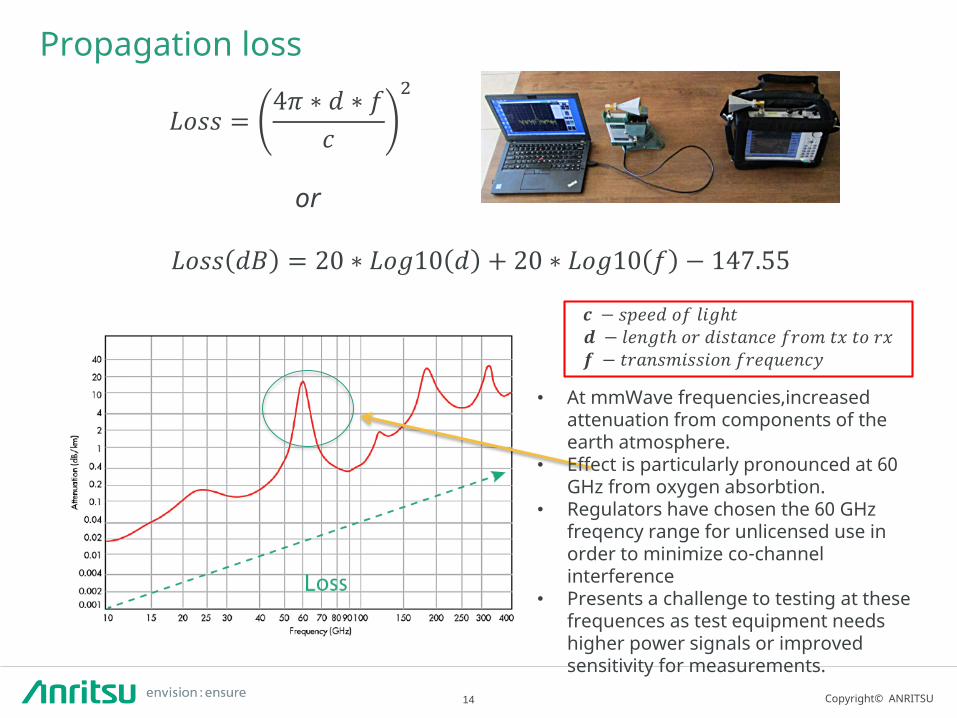
Propagation loss
𝐿𝑜𝑠𝑠 =4𝜋 ∗ 𝑑 ∗ 𝑓
𝑐
2
𝒄 − 𝑠𝑝𝑒𝑒𝑑 𝑜𝑓 𝑙𝑖𝑔ℎ𝑡𝒅 − 𝑙𝑒𝑛𝑔𝑡ℎ 𝑜𝑟 𝑑𝑖𝑠𝑡𝑎𝑛𝑐𝑒 𝑓𝑟𝑜𝑚 𝑡𝑥 𝑡𝑜 𝑟𝑥𝒇 − 𝑡𝑟𝑎𝑛𝑠𝑚𝑖𝑠𝑠𝑖𝑜𝑛 𝑓𝑟𝑒𝑞𝑢𝑒𝑛𝑐𝑦
or
𝐿𝑜𝑠𝑠 𝑑𝐵 = 20 ∗ 𝐿𝑜𝑔10 𝑑 + 20 ∗ 𝐿𝑜𝑔10 𝑓 − 147.55
• At mmWave frequencies,increasedattenuation from components of the earth atmosphere.
• Effect is particularly pronounced at 60 GHz from oxygen absorbtion.
• Regulators have chosen the 60 GHz freqency range for unlicensed use in order to minimize co-channel interference
• Presents a challenge to testing at these frequences as test equipment needs higher power signals or improved sensitivity for measurements.

15 Copyright© ANRITSU
Repeatability
PIN GAP PIN DAMAGE
• Misalignment• Dust and dirt• Non-precision connections
Connector Max Frequency Pin sizeK connector ® 40 GHz 2.92 mmV connector ® 70 GHz 1.8 mmW1 connector ® 110 GHz 1.0 mm

16 Copyright© ANRITSU
Field test challenges
• Antenna arrays• Beamforming
Field testing will change with 5G mobile networks

17 Copyright© ANRITSUSlide Title
O v e r c o m i n g m m W a v e t e s t c h a l l e n g e s

18 Copyright© ANRITSU
Overcoming mmWave test challenges

19 Copyright© ANRITSU
Reduce connections / measure close to DUT
A profile of mismatch uncertainty (dB) values resulting from two reflection coefficients.

20 Copyright© ANRITSU
Reduce connections / measure close to DUT

Photo Image
RF Drone measurementsin mW
Copyright© Anritsu Corporation
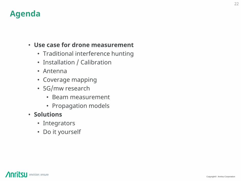
Agenda
• Use case for drone measurement• Traditional interference hunting• Installation / Calibration• Antenna • Coverage mapping• 5G/mw research
• Beam measurement• Propagation models
• Solutions• Integrators• Do it yourself
22

Copyright© Anritsu Corporation
Use case for Drone measurement
• Use case for drone measurement
• Interference hunting
• Coverage mapping / Network planning
• Propagation models
• Antenna Beam characterisation
• Antenna installation : calibration of beams / Backhaul mW
23

Copyright© Anritsu Corporation
Operators coverage
❑ Traditional cellular coverage : drive test in 2D❑ Urban scenario requires 3D : Measurement in buildings.
How about :❑ Non paved road ? ❑ Drone coverage ?
24
Coverage at 200 meters height ?
Traditional 2D drive test.
3D Coverage in Buildings
Copyright© Anritsu Corporation
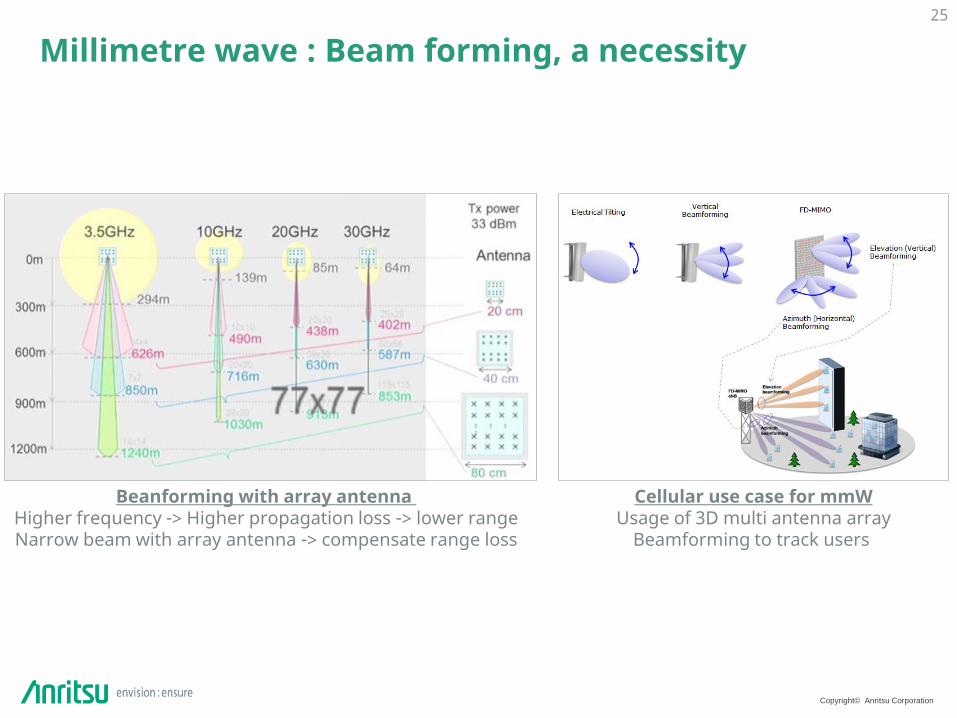
Millimetre wave : Beam forming, a necessity25
Beanforming with array antenna Higher frequency -> Higher propagation loss -> lower rangeNarrow beam with array antenna -> compensate range loss
Cellular use case for mmWUsage of 3D multi antenna array
Beamforming to track users
Copyright© Anritsu Corporation
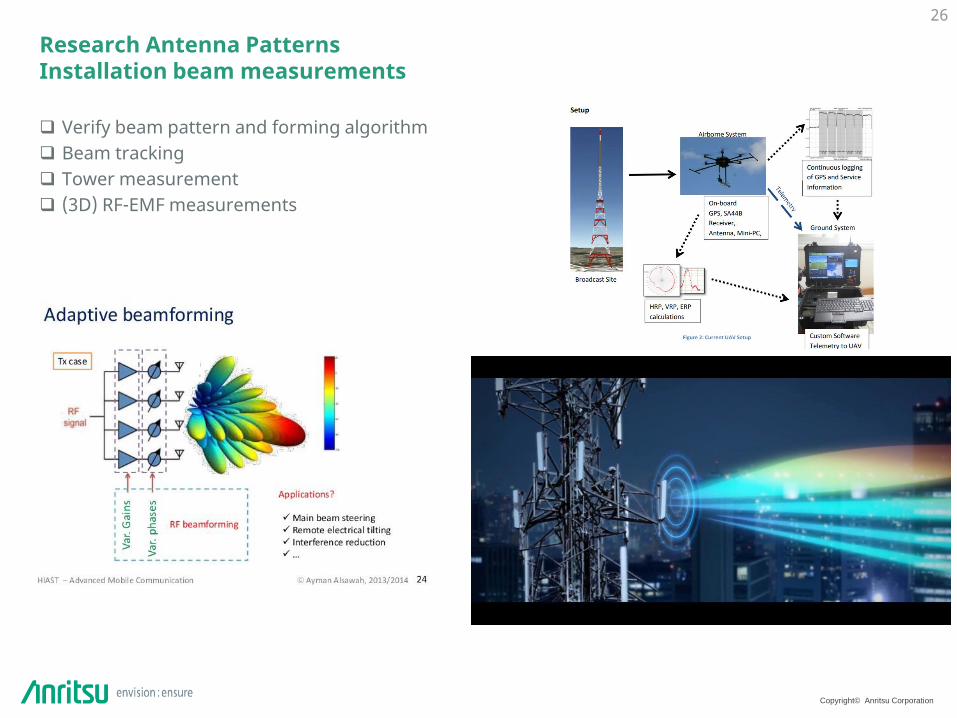
Research Antenna PatternsInstallation beam measurements
❑ Verify beam pattern and forming algorithm❑ Beam tracking ❑ Tower measurement ❑ (3D) RF-EMF measurements
26

Copyright© Anritsu Corporation
Research in Propagation model
❑ Operators need to define theoretical coverage using planning tools.
❑ Planning tools use different propagation models to define coverage
❑ Propagation model are based on real physical measurement campaigns.
❑ Research institute run measurement campaign using drive test which give results in 2D and some measurement in buildings.
27
➔SPA Drones allow a maximum degree of liberty in 3D, ideal for Propagation research.
➔Our solution is good for measuring power, however we cannot get the phase.
Propagation modelVerified with real measurement
Copyright© Anritsu Corporation
Drone Do it yourself
Examples
28

Copyright© Anritsu Corporation
Proof of concepts
❑ Amateur drone based on DJI Phantom 3❑ Kept a camera, mount equipment on the legs.
29
➔Piloting drones commercially usually requires a license.
➔Flying drones require good weather condition : limited wind / no rain.
Copyright© Anritsu Corporation
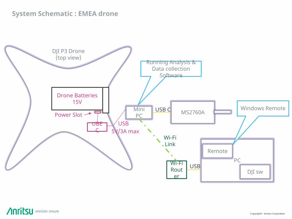
DJI P3 Drone(top view)
System Schematic : EMEA drone
Drone Batteries15V
Power SlotUBE
C 5V/3A max
Mini PC MS2760A
PCWi-Fi Rout
er
USB
USB C
USB
Wi-FiLink
Running Analysis & Data collection
Software
Windows Remote
Remote
DJI sw
Copyright© Anritsu Corporation
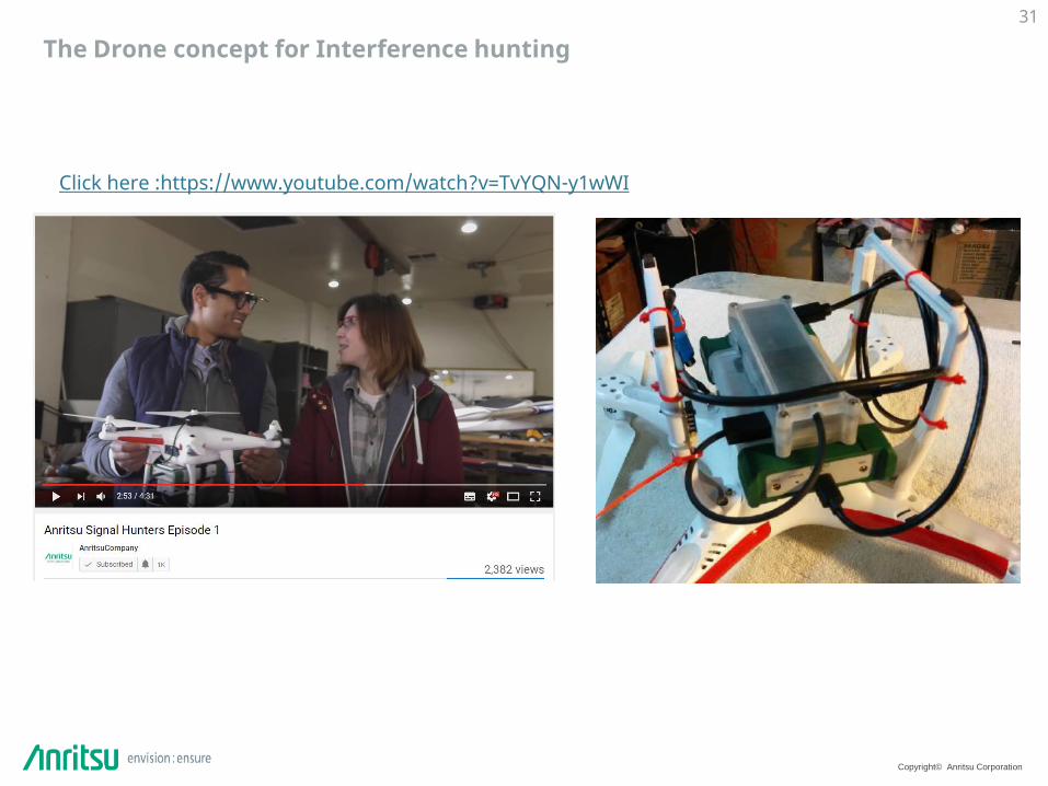
The Drone concept for Interference hunting 31
Click here :https://www.youtube.com/watch?v=TvYQN-y1wWI

Copyright© Anritsu Corporation
Drone challenges
❑ Target Measurements▪ Antenna frequency and pattern▪ Measurement duration
❑ Flight time▪ How long the drone can fly with power drained and the weight.▪ How often do we have to replace batteries
❑ Power consideration▪ How much power they can deliver. Can they provide at least 3A@5V
❑ Mounting & Weight consideration▪ How much the Drone can lift▪ How to fix our instrument to the drone safely without interferce
❑ Control▪ How to control the Drone with accuracy:
✓ Manually in line of Sight (Wi-Fi backhaul)✓ Semi-manual in line of sight with Pre-recorded flight path (Wi-Fi backhaul)✓ Automatic with non Line of Sight ( Cellular backhaul) -> Precise positioning ?
▪ Who is going to pilot the drone▪ Line Of Sight or NOS
❑ Data collection▪ Which operating system▪ What type of control libraries
32
Measurements
Flight time
Weight & Batteries
ControlBackhau
ls
Copyright© Anritsu Corporation
Drone RF measurement up to 110GHz is now possible
33


![Edinburgh Research Explorer · such as the IEEE 802.11ad for local area networking [9] have already considered the mmWave band ranging from 30 GHz to 300 GHz, where field measurements](https://static.fdocuments.us/doc/165x107/5f02260c7e708231d402d005/edinburgh-research-explorer-such-as-the-ieee-80211ad-for-local-area-networking.jpg)