THE CATHODE OSCILLOGRAPH FOR THE STUDY OF M~D … · THE CATHODE OSCILLOGRAPH FOR THE STUDY OF ......
20
TECHNICAL MEMORANDUMS NATIONAL ADVISORY CONtMITTEE FOR AERONAUTICS. No. 255 THE CATHODE OSCILLOGRAPH FOR THE STUDY OF LOV!, IUM AND HI GR FREQUENC IES. By A. Dufour. From \I L ' Ond e E1 ectr iqu e , 11 Nos. 11, Nov. '.922; 12, Dec. 1922.; 13, Jan. 1923. April, 1924. https://ntrs.nasa.gov/search.jsp?R=19930085018 2019-02-03T06:05:41+00:00Z
Transcript of THE CATHODE OSCILLOGRAPH FOR THE STUDY OF M~D … · THE CATHODE OSCILLOGRAPH FOR THE STUDY OF ......
TECHNICAL MEMORANDUMS
NATIONAL ADVISORY CONtMITTEE FOR AERONAUTICS.
No. 255
THE CATHODE OSCILLOGRAPH FOR THE STUDY OF
LOV!, M~D IUM AND HI GR FREQUENC IES.
By A. Dufour.
From \I L ' Ond e E1 ectr iqu e , 11
Nos. 11, Nov. '.922; 12, Dec. 1922.; 13, Jan. 1923.
April, 1924.
https://ntrs.nasa.gov/search.jsp?R=19930085018 2019-02-03T06:05:41+00:00Z

NATIO NA L ADVISORY COMMI TTEE FOR AERONAUTICS .
TECHNICAL MEMORA1~UM NO. 255 .
THE CATHODE OSCI110GRA?H FOR THE STUDY OF
LO YJ , MEDIUM AND HI GE FREQUENCIES. * By A. Dufour .
The obj ect of this wo r k has been to construct an apparatus
for obta ining oscillograms of voltages and currents wh ich are
variable 1[r i t Il res-pect to t i me a nd of the frequency which is con-
stantly met in radio.
The nrinci-ple of the method has been published previously
(in C. R. t 158, p .1339) . My first apparatus was mad e before the
war and gave good resul ts between 10,000 and 750,000 cycles but
vras not very easy to handle. The second apparatus, wh ich VIaS
more easily handled and capable of use fro~TI low frequency to
high frequency by the adgition of the class ical recording cylin-
der for the low frequency , wa s described in the Journal de Phy--
sique, (November, 1920) and in the Bulletin des Inventions (1922) .
*The above translation of an article on the lIoscillograph cathodique ll wa s t aken from Nos. 11, Nov . 1922 , 12, Dec . 1922, 13, J an . 1923 , of 111'0nde Elect rique . !I The translation given is not comnlete. The ori ginal article contains considerable information on t h e nroduction of electr ica l oscilla tions , and is of part i cular value to those engaged in high frequency electrical investi gations. Only the portions of the a rticle deal ing with the construction and use of the apparatus have been translated , the author ' s s tyle and arr angement being retained as far as possible . The translation was made by Mr . H. E. Miller , of the technical staff of the Langley Memorial Aeronautical Laboratory, as the article is of particular interest because of the possibility of emplo ying the anparatus descr ibed as Em indicator for use on high- speed internal combustion engines .
.'
- 2 -
The apparatus descr ib ed in this memo is the resuit of a
long study which was delayed by the war and lack of means despi te
the a id of the Serv i ce d.es Inventions ~'hich desired to use the
apparatus .
Principle .
In order to rrake clear the use of the oscillo graph ~ I will
revi ew in a few words the principle of the Braun tube from :;Thi ch
it has been derived:
A stre2.m of ca thode rays emi tted normally by a cathode trav
els in a st rai ght line in the tube~ go ing further as the vacuum
i s increaset. A metallic shi eld containing a small hole allowing
only a srrall port ion of the electrons to pas s through~ produces
a brilli ant spot on a fluorescent scr een p laced in their path.
An electrostatic or magnetic fie ld p l aced between shi eld and
scr een will cause this spot to be disp lac ed due to the dev iation
produced by these forces acting on the moving electron. If these
fields vary in strength a nd direction with time~ a bright line
will be seen on the scr een. If uni f orm transverse mot ion is
given to the snot, there ~ ill be seen the cyc le of events, which
can also be photographed .
Let 8 .= deviation, H = intensity of magnetic or electr ic
field~ e = charge on electron~ m = its mass , L = length
throu gh ~hich the action occurs and v = velocity of the electron.
Then the dev iations are :

,-'
- 3 -
8 He 1 i n an electrostatic field. = V
2 m
8 = He L in a magnetic field. m v
Because of the negli~ible mass of the ~ectron, the devia-
t ions giv en~ as f a r a s can be observed, are exactly the varia-
tions in the f ields s tudied, even in the high frequencies where
the inertia of mechanical system causes failure in the ordinary
oscillograph. Be s ides its use as an oscillograph it can be em
ployed to determine a difference of phase of two systems having
the same frequency by having two fields opera te directly at
right angles to each other on the tube, one tube fed by the
first system or circuit and the other by the second circuit .
Several methods of spreading out the oscillations in a
transverse direction a re used to suit the frequencies studied .
These 7ill be explained as they are reached. Since the emission
of electrons is discontinuous, a question mi ght be raised as to
the po ssibility of discontinuous effect on the screen . As a
matter of f a ct a little calculation sho s that about 300,000
el ectrons rea ch each square millimeter of the plate per second
so there is no visible discontinuity . While the value on
which the formulae are based does not remain constant as the
derivation requires, the change ~ith velocity is not apprecia-
ble until near the velocity of light . As this is never ap
proached even ~ith the hi gh velocities used here, this is not
s erious.
"
- 4 -
The osc:"llograph and accessories can be placed easily in a
room about 20 feet long by about 15 feet wide. The only require-
YTlents are that the temperature be fairly constant and that lt be
po ssible to rna kG the room dark. The room could be lighted by
lights cove=ed TIit~ a liquid screen of bichromate of potassium.
The apparatus has been des i gned for use in a room li ':.;htsd VIi th
white light but the other arrangement is preferable as it en-
a"bles the loading, exposing, developing, fixing and printing to
be done in the sa~G room without danger of fogging .
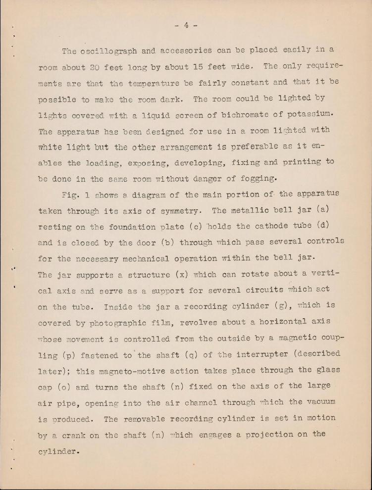
Fig. 1 sholVs a diagram of the main portion of the apparatus
t aken through its axis of syrr~etry. The metallic bell jar (a)
resting on the foundation u late (c) holds the cathode tube (d)
a nd is closed by the door (b) through 1~rhich pass several controls
for the necessary mechanical operation within the bell jar.
The jar supports a structure (x) which can rotate about a verti -
cal axis and serve as a suuport for several circuits lrTh ich a ct " -
on the tube . Inside the jar a recording cylinder ( g), ~hich is
covered by photographic f ilm, revolves about a horizontal axis
"Those movement i s controlled from the outs ide by a magnetic coup-
ling (p) fastened to the shaft (q) of the interrupter (described
later); this magneto-mot ive action takes place through the glass
cap (0) and turns the shaft (n) fixed on the axis of the large
a i r pipe, opening into the a i r chaI1..Dol through '7hich the vacuum
is nroduced. The rerrovable recording cylinder is set in motion
by a crank on the shaft (n) ":"Thich en?,ages a proj ection on the
cylinder .
\ '
- 5 -
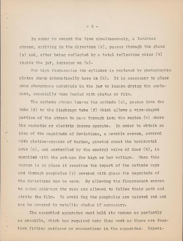
In order to record the time simultaneously, a lumir.ous
str eam , arri ving in t he direction (r), passes through the glas s
(s) and , after being r eflected by a tota l reflection prism (t)
inside the jar, i mpinges on (u).
For hi gh frequencies the cylinder is rep lac ed by photographic
p l a tes shown schematically here in (h). It is necessary to place
some phospho l'U s anhydride in the jar to insure drying the enclo
sur e , especially ',hen l oaded wi th plates or film.
The cathode s ream leaves the cathode (e), passes dovrn th e
t ube (d) to t he d iaphragm tube (f) qhich allows a wire-shaped
portion of · the stream to pa s s through into the region (v) where
the magnetic or electric forces opera te . In order to obta in an
i dea of the ma gnitude of deviations, a rrovable screen, covered
n ith platino-cyanide of ba rium, p ivot ed about the horizontal
axis (n ), and controlled by the central valve of door (b), is
s1,lpDl ied vIi t h the set-ups for high or low voltage . limen this
Gcreen is in p l ace it receives the impact of the cathode rays
and th rough peepholes (i) covered with glass the magni tude of
t he de i ations can be seen. By allowing t he fluorescent scr een
to S'7 inf:.' side'-'ays the r ays a re a llowed to follow their path and
s trike the film. To avoid fo g the peepholes a re Dainted red and
can be cover ed by metall i c shades if nec essary .
The assembled apparatus must hold it s vacuum as perfectly
as po ssi b le, nh ich has required very fine TIork as there a re four
t een fittin~ surfa c es or connections in the apparatus . Experi-

"
- 6 -
ence has sho n that the obtaining of a vacuum suitable for proper
oper at ion of the tube is more rapid at the end of a pe riod of op
eration than at the beginning , due to gases occluded in the metal
being purged little by little. The apparatus is therefore kept
under low pressure when not in use.
In operation ~reat care must be taken of the fitting sur
faces because a hard body co mpressed by a force of 700 kilograms
(1543 pounds) due to the a t mo sphere VJould ruin the fi tting sur
faces of the door (b). At each closing the surfaces are greased
n ith vaseline .
Ca thode Tubes.
Various forms of tubes that can be used are shown in Fig . 2.
Lower surface of tube A f it s on the upper su r faces of the other
tubes which in turn fit on the bell jar. Combination AB is
used t o study ma~netic fields . Deviations of 1 millimeter for a
f i eld of 30 gauss a cting through 5 centime ters are obtained .
AC i s used for volta~e curv es . A millime ter deviation is ob
t a in ed with 10 volts between plates 8 centimeters long and 5 milli
rn.eter s apart .
AD is used ,hen t wo electric fields a re caused to operate
on the stream . The condensers a re at ri ght angl es to each other.
Tubes E, F, G, each furnished with t wo A tub es are used to
r ecord s imultaneously t wo currents or volta es or one of each.
They can only be used in the low frequ encies. The branches must
be scr eened so that there is no reaction of one tube on the other.

- 7 -
There i s some irregularity of a ction due to the fac t that the
instantaneous pressures in the t wo t ubes a r e not th e same. A
precaution to be noted is that the bell j a r s~ould be heated
before re~ oving t ub es as they are liable to be broken.
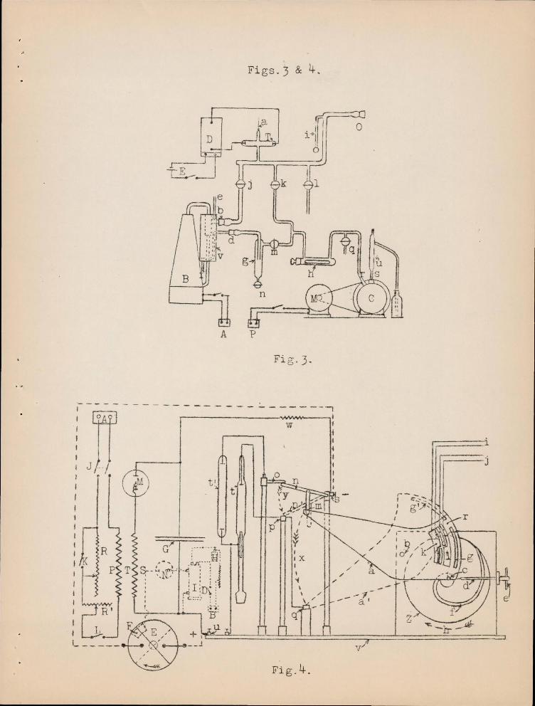
Apparatus for making the vacuum.
The vacuum must be renewed each time the appar atus is load
ed witt film, and a pump system to obta in this easily has been
devi sed . . The circuit is shown in Fig . 3 . The pr eparato r y vac
uum is made by the auxiliary pump C ith valve (k) open and
the remainder closed . The tube (h) i s drying tube . Af t e r the
manometer (v) shows the hi ghes t vacuum which C can give ,
valve (k) is closed and valves (m ) and (j) opened in succession .
" The mercury vapor-pur.lp B t hen p roduces the h i gh vacuum. Ob
ser va tion of the a rc T shoqs the extent of vacuum. Wh en 70 r k
is started valve (m) should be clo sed befo re s toppi ng the pre
par a tory pump . Air is let in by opening valve (1) . As it takes
t i me to get pump B to function well , it i s usually kept war m
and running, dischar ging into t ube (g) and through va l ve (n)
when wo r k is temporar ily stopped . The glass tubing used has
been ar ranged to avoid temperature stresses -
Recording cylinder fo r low and medium frequencies .
The dimensions of the c ylinder a re 150 millimeters (5 . 91
inches) i n diameter and 50 mi llimeter s (1 . 97 inches) in length .
A f luorescent scr een i s f it ting d irectly over the fi l m. The

- 8 -
film is, of course , held flat on the cylinder, which rotates
at the r ft te of 10 +,urns -per second. The curves would t angle up
due to operation during s6veral turns unless some method of lon
gitudinal di3p lacement VTere devised, such as a sinuso i dal field
V'TOLlld p:cod.uce. Another method is to have the tube li ght up
only during one re1701u tion of t he cylinder, which will now be
desc r ibed. .
InterTupter for 10'.7 a.nd med ium freql.1.encies.
Fig. 4 sho~s a schematic drawing of the set-up. The inter
rupter Z is a flywheel v.i th a helicoidal groove into !hich
the finger (c) can be inserted. The arm (a) i s pulled in the
direction of the arrow (x) . The rod (n), connected to (a) by
the friction~l connection (m) , travels from (0) to (p) breaking
the circuit of tube (t' ) and l i ghting tube (t), whi ch is the one
used for pictures . I n order to keep voltages and currents con
stan t i t i s necessary to use a tube (t') whOSE: resistance i s
the same a s that of (t).
The electric circuits a re of two kinds . One is an a rrange
ment to obtain hif?;h volta.ge by means of an electrostatic machine.
The other uses a transformer vrith a rectifier . The electro
s t a tic r:1ach i ne a l ':IaYs bui l d s up to the same polari ty, because
a negatively cha r ged plate is held opposite the upper end of
the cross piece of he machine . This plate is charged by a
transformer and rec t ifi er. The electro s tatic machi.ne gives best
results but has very small power . The transformer can give

- 9 -
voltages up to 60~OOO . A steadying condenser must of course
be used vli th the transformer, to give mOre constant voltage.
Sectors (k) and (1) , in a r m (a) Fig. 4, are used ~ith
bru sh contacts to operate, automati cally, switches starting the
phenomenc stu~ied . Slot (g) Fig. 4, i s used in connectio~
v! i th t he exact measurement of the speed of rota tion of th3 cyl -
indeT wh ich, as is seen in Fi g . 5, is on the same shaft with t he
. + ..!.. I n,,erIupver. Ref er ring to Fig. 5, the me thod of speed lY.easu re-
ment i s ve r y eas i 1 v seen . Light from a n i tro gen l amp S go es
through (f) a slot in th e prong of a t uning fork and is t hen
converged by a lens L th rough the slot (g) Fig . 4 . From there
it enters the bell jar and is reflect ed on to the recording
cylinde r. As it can only enter through the sli t (f) Fig. 4,
vibration of the tuning fork per mits onJ..y period.ic flashes on
to the fi l m. The period of the f ork is known so that the speed
can be obta ined . Thi s completes th~ description of t he method
used ordinarily for low and medium frequencies . In extending
the method to damp ed wav es of high frequency a special switch
i s added .
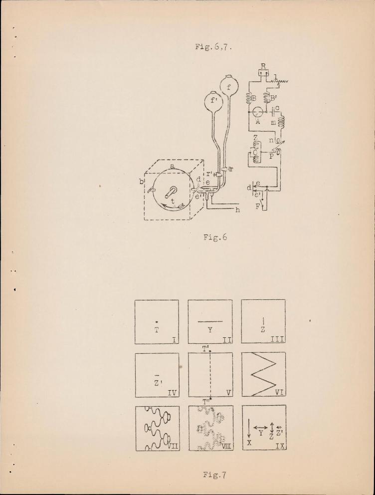
Mercury) f rom t ub es (f) and (f l ), (Fig. 6), floffs through
the nozzles (e) and (e') . ·.-Jhen the insula t ed metallic a r m on
t he disk (d) comes a round, it makes contact with ~he mercury ,
c l osing the circuit for the short period of time required .
Th e br eak is mad e v7i t hou t an a rc·
A th i rd me t hod for low f requency involves t he use of a
constantly decreas ing magnetic field, such as is obtained by

10 -
opening a current conta. ining iron, ,to cause a displacement of
the spot acro ss t he cylinder so tha t a helix is produced ' on the
f ilm. On thi s helix i s superuo sed the curve of phenomena stud
ied . It ca n be used up to f r equencies of 11, 000 per second .
Ecuipment fo r. h t gh f requencies.
For lligh f requeno ies a set of photo o::r a,phic p l a tes i s used
ins tead of the recording .cyl i nder and the interrupter . The
pIa tes, 6 i n number, l..'. r e 130 rom (5 . 12 in . ) long and 125 mm
(.4 . 92 in.) v!ide . By mean s of a control on the door of the bell
jar a plate wh i ch has been exposed can be dropped , 80 that it
is no longer exposed , to make way f or the next pla te.
Me tpod of r ecording .
As t he pho t ogr aph i c plates a re stationary , the displace
ments on t he p l a tes are obtained by t he acti on of elect r ostat i c
or electromagnetic forces . I n Fig . 7 (1) , t he letter T mar ks
t he mo tionless cathode sot . II sho'i!s the l ine drawn b y large
o sci 11a t i ons ) h ere ca lled Y. I I I shows t he line drawn by the
smal l er o scilla t i ons , here called Z. IV shows another l i ne
produce~ oy oscillations Z1. Finally V i llustrate s a l ine ob
ta i ned by a sweeping action X produ'ced by breaki ng a magnetic
c ircuit conta i n i ng i ron . ~ I shows a comb~nation of X and Y
act ions . VII shows a com~ inat i on of X, Y and Z acti ons. VIII
sho vrs a combina ti on of al l the a.ctions X, Y, Z and Z1. IX i s a
vector i a l pr esentation of the variou s a cti ons .
In t a king a record of h i gh frequency phenomena the sweep
ing action X and an osci 11a tory Y action a re us ed a s acces-

- 11 -
sories to the Z phenomena studied. The Y oscillations of
large ampl i tude serve ~o lengthen out the record. In th e high
est frequencies Z are also acce s sory oscillations and Zr
are those stuct.ied. Since the sweeping action is ve ry fast, the
tube need only be li ghted a very short time; which helps to
preserve the tub e and enables it to be used under the highest
vol tages >
The power required is too grea t for my electro stat ic ma
chine , cOffipelling the use of a transformer and rectifier. It
is n ecessary that the tube be used when the voltage supplied
is the right part of the cycle fo r operat ion of the tube. By
means of a synchronous motor this is accompl ished. All the
s"rli t ching op erations are done s a tisfactorily by an automatic
system sho v-m in Fig . 8.
The a r m (b) is held clear of swi tches 1 to 5 by the spring
(e) . At the ri ght moment, indicated by the rinf2;ing of a bell,
a tr i gger is pulled , releasing the a rm (b), "Th i ch opera tes all
the switches in the order I t o 5. Adjustments of the posi
tions of the switches allo",7 considerable control of the timing
of t he various circu its .
Both this circu i t a.nd the arrangement for low and medium
frequencies h av e ~iven very satisfactory resul ts. Several sam
ple oscillo gra~s of the wo r k done by the low frequency arrange-
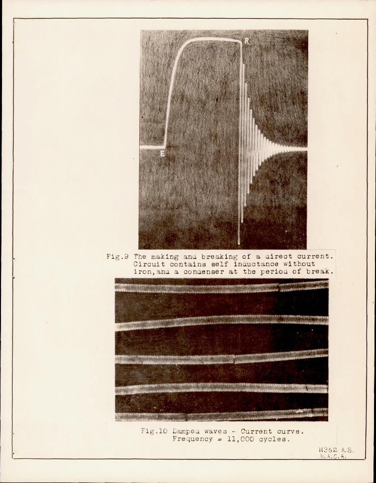
ment a re included at t he end of this report. Fig . 9 shows the
current tirre curve for open in and clo sing of an electric cir-

- 12 ...
cuit containing an air inductance, E to R is the shape of the
current time curve on clos i ng the circuit. The oscillatory por
tion beyond R. is the osci lla to l'y discharge Ylfh ich takes place
across the a ir gap at the point where the circuit is broken.
Fig. 10 shows a continuous wave alternating current whose
frequency i s 11,000 cycles per second. Fi:g . 11 is an oscillo
grar!l of dar.1ped waves with a frequency of 1,100,000, wh ile Fig.
12 shows the current time curve for an antenna tuned to receive
waves whose frequency i s 115 , 000 . The waves are damped oscil
lations from a spark transmitting set.
Y/hile no illustrations of the work done by the high fre
quency arrangement are included in this translation, the orig
inal article shows as good oscillograms for higher frequency .
The ran e of the low frequency arrangement is from ° to 50,000
for sustained oscillations and from ° to several million for
damped oscillations ".vhile the high frequency arrangement can be
used from 10,000 to 10,000 , 000 for continuous waves and for
damped waves has reached 220,000,000 cycl es per second .
In combination the o sc illograph can furnish oscillograms
of currents ani volta~e s fro m ° to 10,000,000 cycles per second
for sustained wav es and ° to 220,000,000 cycles per second for
damped waves, vTh ich includEs every frequency used from the lowest
to the h i ghest . It therefore has no practical limit.
Translated by Na tiona l ri.dvi so ry Commi ttee for Aeronautics .

Fi gs . l & 2 .
~: I
I
Fi g .l.
A c E F G I
" i~ " ~ • I
Y V yy
v Fi g . 2.
Figs.3 & 4.
A P
Fi g· 3·
,- - - - - - - - - - - - - - - - - - ~ - - - - --I
I j
I W ,
I :
o
p I
~ I IX I
\ ~
\ \ / \ /'
q
Fig.4 .
~
I
" / .
/ a
__ - -.:1,-0.

~ ~-,j I
1 ' I j
1 I I I I I I'
" ro I ... ~'-j
I' ,I II
Fig·5
, I ' , \ ..0 , I , 1 , I , I I I
H' I ;=t I ,
I ,
T I
ZI
IV
Fig r -, . 0, ( .
Fi g . 6
y
TI .
'J I I 1 I I I I V
Til
Fig·7
I Z
III
!y!~ Z ZI X IX

Fig .S
..
r
Fig.3 The making an breaking of a irect current . Circui t contains self inuuct a nce without iron, a na con eneer at the of break.
f i g .10 ampe u waves - Current curve. Fre ~uency = 11, 000 cycles .
11 2' !J2 1\ .5. N • . C. A.
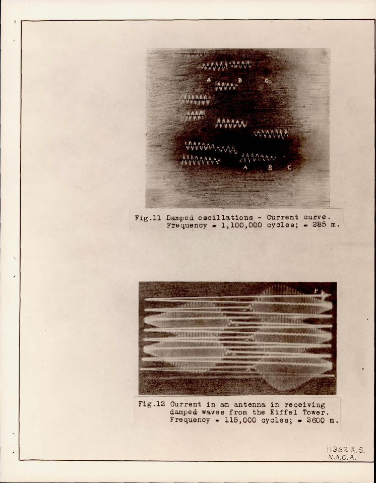
Fig.ll Damped o~cillations - Current curve. Frequency. 1,100,000 cycles; - 285 m.
Fig.12 Current in an antenna in receiving damped waves from the Eiffel Tower. Frequency - 115,000 cycles; - 2600 m.
1136:<' A.S. N.A..C . A.