The Carbonation Behaviors of Limestone Particle in …The Carbonation Behaviors of Limestone...
7
Journal of Power and Energy Engineering, 2013, 1, 1-7 http://dx.doi.org/10.4236/jpee.2013.12002 Published Online May 2013 (http://www.scirp.org/journal/jpee) 1 The Carbonation Behaviors of Limestone Particle in Oxygen-Fuel Circulating Fluidized Bed O 2 /CO 2 Flue Gas Jianyu Shang 1* , Zhongliang Liu 1 , Chunbo Wang 2 1 College of Environmental and Energy Engineering, Beijing University of Technology, Beijing, China; 2 School of Energy and Power Engineering, North China Electric Power University, Baoding, China. Email: * [email protected] Received April 12 th , 2013; revised May 12 th , 2013; accepted May 27 th , 2013 Copyright © 2013 Jianyu Shang et al. This is an open access article distributed under the Creative Commons Attribution License, which permits unrestricted use, distribution, and reproduction in any medium, provided the original work is properly cited. ABSTRACT Limestone powder is still applied as SO 2 sorbent in emerging oxygen-fuel circulating fluidized bed boiler, but its car- bonation in O 2 /CO 2 flue gas is an unclear problem. For a better understanding of carbonation behaviors, the tube fur- nace heating system was built for simulating circulating fluidized bed boiler flue gas by regulating the supply of O, CO 2 , N 2 , SO 2 and H 2 O, and Carbonation reaction was tested. Thermal gravimetric analysis and scanning electron microscopy were used. It was found that carbonation is closely related to temperature, CO 2 concentration, impurities, water vapor, and cycle times; high temperature can promote carbonation process; high concentration of CO 2 can inhibit the chemical reaction stage speed of carbonation process, but it has little effect on the final conversion rate; water vapor can increase the final conversion rate of carbonation; the cycle times will reduce the activity of carbonation. The presence of car- bonation turns the traditional boiler flue gas indirect desulfurization model into indirect desulfurization mechanism which does not have a negative impact on SO 2 removal efficiency. Keywords: Oxygen-Fuel; Circulating Fluidized Bed; Limestone Particle; Carbonation; Desulfurization; Production Layer 1. Introduction For many coal-fired power plants in China, limestone is widely used in dry desulfurization technology [1-4]. In traditional boilers, limestone (Figure 1) will be thermally decomposed into porous CaO particles (Figure 2) in high temperature flue gas, and then chemically react with SO 2 to produce CaSO 4 . This type of SO 2 removal is called indirect desulfurization reaction [5-7], and the chemical equations are 3 2 CaCO s CaO s CO g (1) 2 2 4 1 CaO s SO g O g CaSO s 2 (2) In fact, it may not be quite that simple for oxygen-fuel circulating fluidized bed (CFB) flue gas, because car- bonation will happen at that carbon-dioxide-rich atmos- phere. CaO carbonation is actually a reversible reaction about CaCO 3 calcinations [8] as shown in Figures 3 and 4. The phenomenon that limestone is partly calcined into Figure 1. Unreacted limestone particle. CaO does exist at the CFB oxygen-rich combustion zone where CO 2 concentration is lower and temperature is relatively higher, and when these CaO reach carbon- dioxide-rich zone it will present carbonation reaction [9]. In other words, these CaO will be finally reduced to CaCO 3 again at main flue zone where CO 2 concentration is >80% [10]. The chemical equation is 2 CaO s CO g CaCO s 3 (3) * Corresponding author. Copyright © 2013 SciRes. JPEE
Transcript of The Carbonation Behaviors of Limestone Particle in …The Carbonation Behaviors of Limestone...
Journal of Power and Energy Engineering, 2013, 1, 1-7 http://dx.doi.org/10.4236/jpee.2013.12002 Published Online May 2013 (http://www.scirp.org/journal/jpee)
1
The Carbonation Behaviors of Limestone Particle in Oxygen-Fuel Circulating Fluidized Bed O2/CO2 Flue Gas
Jianyu Shang1*, Zhongliang Liu1, Chunbo Wang2
1College of Environmental and Energy Engineering, Beijing University of Technology, Beijing, China; 2School of Energy and Power Engineering, North China Electric Power University, Baoding, China. Email: *[email protected] Received April 12th, 2013; revised May 12th, 2013; accepted May 27th, 2013 Copyright © 2013 Jianyu Shang et al. This is an open access article distributed under the Creative Commons Attribution License, which permits unrestricted use, distribution, and reproduction in any medium, provided the original work is properly cited.
ABSTRACT
Limestone powder is still applied as SO2 sorbent in emerging oxygen-fuel circulating fluidized bed boiler, but its car-bonation in O2/CO2 flue gas is an unclear problem. For a better understanding of carbonation behaviors, the tube fur-nace heating system was built for simulating circulating fluidized bed boiler flue gas by regulating the supply of O, CO2, N2, SO2 and H2O, and Carbonation reaction was tested. Thermal gravimetric analysis and scanning electron microscopy were used. It was found that carbonation is closely related to temperature, CO2 concentration, impurities, water vapor, and cycle times; high temperature can promote carbonation process; high concentration of CO2 can inhibit the chemical reaction stage speed of carbonation process, but it has little effect on the final conversion rate; water vapor can increase the final conversion rate of carbonation; the cycle times will reduce the activity of carbonation. The presence of car-bonation turns the traditional boiler flue gas indirect desulfurization model into indirect desulfurization mechanism which does not have a negative impact on SO2 removal efficiency. Keywords: Oxygen-Fuel; Circulating Fluidized Bed; Limestone Particle; Carbonation; Desulfurization; Production
Layer
1. Introduction
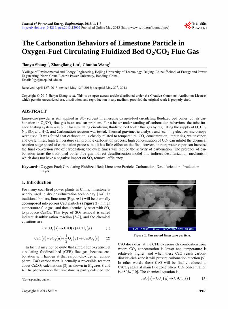
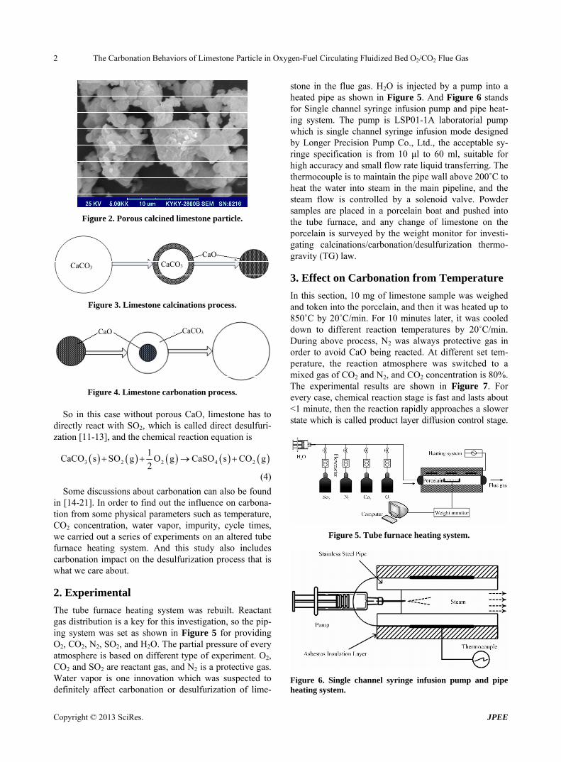
For many coal-fired power plants in China, limestone is widely used in dry desulfurization technology [1-4]. In traditional boilers, limestone (Figure 1) will be thermally decomposed into porous CaO particles (Figure 2) in high temperature flue gas, and then chemically react with SO2 to produce CaSO4. This type of SO2 removal is called indirect desulfurization reaction [5-7], and the chemical equations are
3 2CaCO s CaO s CO g (1)
2 2 4
1CaO s SO g O g CaSO s
2 (2)
In fact, it may not be quite that simple for oxygen-fuel circulating fluidized bed (CFB) flue gas, because car-bonation will happen at that carbon-dioxide-rich atmos-phere. CaO carbonation is actually a reversible reaction about CaCO3 calcinations [8] as shown in Figures 3 and 4. The phenomenon that limestone is partly calcined into
Figure 1. Unreacted limestone particle. CaO does exist at the CFB oxygen-rich combustion zone where CO2 concentration is lower and temperature is relatively higher, and when these CaO reach carbon- dioxide-rich zone it will present carbonation reaction [9]. In other words, these CaO will be finally reduced to CaCO3 again at main flue zone where CO2 concentration is >80% [10]. The chemical equation is
2CaO s CO g CaCO s 3 (3) *Corresponding author.
Copyright © 2013 SciRes. JPEE
The Carbonation Behaviors of Limestone Particle in Oxygen-Fuel Circulating Fluidized Bed O2/CO2 Flue Gas 2
Figure 2. Porous calcined limestone particle.
CaCO3 CaCO3 CaO
Figure 3. Limestone calcinations process.
CaCO3 CaO
Figure 4. Limestone carbonation process. So in this case without porous CaO, limestone has to
directly react with SO2, which is called direct desulfuri-zation [11-13], and the chemical reaction equation is
3 2 2 4 2
1CaCO s SO g O g CaSO s CO g
2
(4)
Some discussions about carbonation can also be found in [14-21]. In order to find out the influence on carbona- tion from some physical parameters such as temperature, CO2 concentration, water vapor, impurity, cycle times, we carried out a series of experiments on an altered tube furnace heating system. And this study also includes carbonation impact on the desulfurization process that is what we care about.
2. Experimental
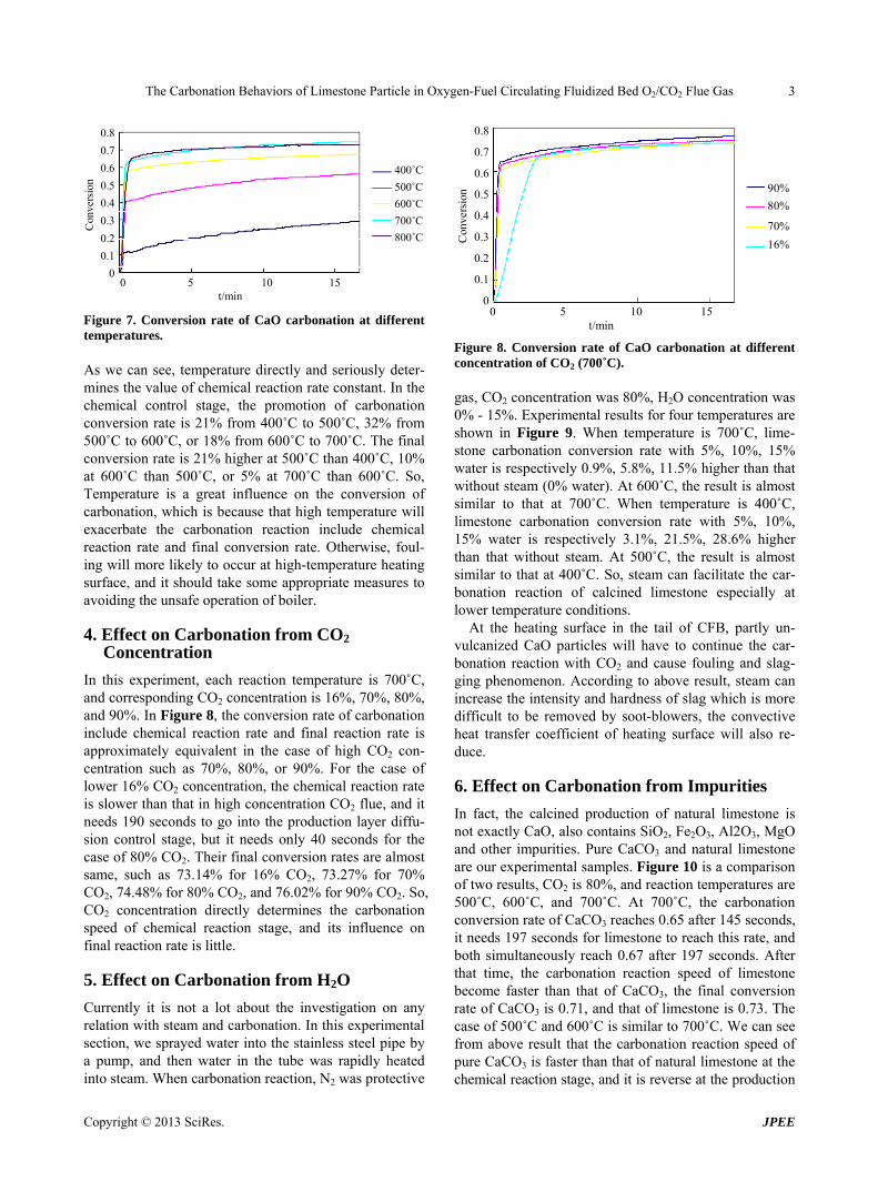
The tube furnace heating system was rebuilt. Reactant gas distribution is a key for this investigation, so the pip-ing system was set as shown in Figure 5 for providing O2, CO2, N2, SO2, and H2O. The partial pressure of every atmosphere is based on different type of experiment. O2, CO2 and SO2 are reactant gas, and N2 is a protective gas. Water vapor is one innovation which was suspected to definitely affect carbonation or desulfurization of lime-
stone in the flue gas. H2O is injected by a pump into a heated pipe as shown in Figure 5. And Figure 6 stands for Single channel syringe infusion pump and pipe heat-ing system. The pump is LSP01-1A laboratorial pump which is single channel syringe infusion mode designed by Longer Precision Pump Co., Ltd., the acceptable sy-ringe specification is from 10 μl to 60 ml, suitable for high accuracy and small flow rate liquid transferring. The thermocouple is to maintain the pipe wall above 200˚C to heat the water into steam in the main pipeline, and the steam flow is controlled by a solenoid valve. Powder samples are placed in a porcelain boat and pushed into the tube furnace, and any change of limestone on the porcelain is surveyed by the weight monitor for investi-gating calcinations/carbonation/desulfurization thermo- gravity (TG) law.
3. Effect on Carbonation from Temperature
In this section, 10 mg of limestone sample was weighed and token into the porcelain, and then it was heated up to 850˚C by 20˚C/min. For 10 minutes later, it was cooled down to different reaction temperatures by 20˚C/min. During above process, N2 was always protective gas in order to avoid CaO being reacted. At different set tem-perature, the reaction atmosphere was switched to a mixed gas of CO2 and N2, and CO2 concentration is 80%. The experimental results are shown in Figure 7. For every case, chemical reaction stage is fast and lasts about <1 minute, then the reaction rapidly approaches a slower state which is called product layer diffusion control stage.
Figure 5. Tube furnace heating system.
Figure 6. Single channel syringe infusion pump and pipe heating system.
Copyright © 2013 SciRes. JPEE
The Carbonation Behaviors of Limestone Particle in Oxygen-Fuel Circulating Fluidized Bed O2/CO2 Flue Gas 3
400˚C
500˚C
600˚C
700˚C
800˚C
0.8
0.7
0.6
0.5
0.4
0.3
0.2
0.1
0
Con
vers
ion
0 5 10 15 t/min
Figure 7. Conversion rate of CaO carbonation at different temperatures. As we can see, temperature directly and seriously deter-mines the value of chemical reaction rate constant. In the chemical control stage, the promotion of carbonation conversion rate is 21% from 400˚C to 500˚C, 32% from 500˚C to 600˚C, or 18% from 600˚C to 700˚C. The final conversion rate is 21% higher at 500˚C than 400˚C, 10% at 600˚C than 500˚C, or 5% at 700˚C than 600˚C. So, Temperature is a great influence on the conversion of carbonation, which is because that high temperature will exacerbate the carbonation reaction include chemical reaction rate and final conversion rate. Otherwise, foul-ing will more likely to occur at high-temperature heating surface, and it should take some appropriate measures to avoiding the unsafe operation of boiler.
4. Effect on Carbonation from CO2 Concentration
In this experiment, each reaction temperature is 700˚C, and corresponding CO2 concentration is 16%, 70%, 80%, and 90%. In Figure 8, the conversion rate of carbonation include chemical reaction rate and final reaction rate is approximately equivalent in the case of high CO2 con-centration such as 70%, 80%, or 90%. For the case of lower 16% CO2 concentration, the chemical reaction rate is slower than that in high concentration CO2 flue, and it needs 190 seconds to go into the production layer diffu-sion control stage, but it needs only 40 seconds for the case of 80% CO2. Their final conversion rates are almost same, such as 73.14% for 16% CO2, 73.27% for 70% CO2, 74.48% for 80% CO2, and 76.02% for 90% CO2. So, CO2 concentration directly determines the carbonation speed of chemical reaction stage, and its influence on final reaction rate is little.
5. Effect on Carbonation from H2O
Currently it is not a lot about the investigation on any relation with steam and carbonation. In this experimental section, we sprayed water into the stainless steel pipe by a pump, and then water in the tube was rapidly heated into steam. When carbonation reaction, N2 was protective
90%
80%
70%
16%
0 5 10 15 t/min
0.8
0.7
0.6
0.5
0.4
0.3
0.2
0.1
0
Con
vers
ion
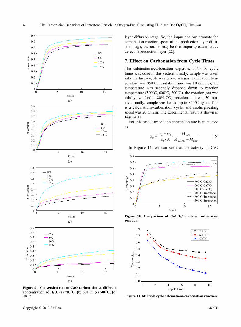
Figure 8. Conversion rate of CaO carbonation at different concentration of CO2 (700˚C). gas, CO2 concentration was 80%, H2O concentration was 0% - 15%. Experimental results for four temperatures are shown in Figure 9. When temperature is 700˚C, lime-stone carbonation conversion rate with 5%, 10%, 15% water is respectively 0.9%, 5.8%, 11.5% higher than that without steam (0% water). At 600˚C, the result is almost similar to that at 700˚C. When temperature is 400˚C, limestone carbonation conversion rate with 5%, 10%, 15% water is respectively 3.1%, 21.5%, 28.6% higher than that without steam. At 500˚C, the result is almost similar to that at 400˚C. So, steam can facilitate the car-bonation reaction of calcined limestone especially at lower temperature conditions.
At the heating surface in the tail of CFB, partly un- vulcanized CaO particles will have to continue the car-bonation reaction with CO2 and cause fouling and slag-ging phenomenon. According to above result, steam can increase the intensity and hardness of slag which is more difficult to be removed by soot-blowers, the convective heat transfer coefficient of heating surface will also re-duce.
6. Effect on Carbonation from Impurities
In fact, the calcined production of natural limestone is not exactly CaO, also contains SiO2, Fe2O3, Al2O3, MgO and other impurities. Pure CaCO3 and natural limestone are our experimental samples. Figure 10 is a comparison of two results, CO2 is 80%, and reaction temperatures are 500˚C, 600˚C, and 700˚C. At 700˚C, the carbonation conversion rate of CaCO3 reaches 0.65 after 145 seconds, it needs 197 seconds for limestone to reach this rate, and both simultaneously reach 0.67 after 197 seconds. After that time, the carbonation reaction speed of limestone become faster than that of CaCO3, the final conversion rate of CaCO3 is 0.71, and that of limestone is 0.73. The case of 500˚C and 600˚C is similar to 700˚C. We can see from above result that the carbonation reaction speed of pure CaCO3 is faster than that of natural limestone at the chemical reaction stage, and it is reverse at the production
Copyright © 2013 SciRes. JPEE
The Carbonation Behaviors of Limestone Particle in Oxygen-Fuel Circulating Fluidized Bed O2/CO2 Flue Gas 4
0%
5%
10%
15%
0.9
0.8
0.7
0.6
0.5
0.4
0.3
0.2
0.1
0
Con
vers
ion
0 5 10 15 t/min (a)
0% 5% 10% 15%
0.9
0.8
0.7
0.6
0.5
0.4
0.3
0.2
0.1
0
Con
vers
ion
0 5 10 15 t/min (b)
0% 5% 10% 15%
0.8
0.7
0.6
0.5
0.4
0.3
0.2
0.1
0
Con
vers
ion
0 5 10 15 t/min (c)
0.9
0.8
0.7
0.6
0.5
0.4
0.3
0.2
0.1
0
Con
vers
ion
0% 5% 10% 15%
0 5 10 15 t/min (d)
Figure 9.Conversion rate of CaO carbonation at different concentration of H2O. (a) 700˚C; (b) 600˚C; (c) 500˚C; (d) 400˚C.
layer diffusion stage. So, the impurities can promote the carbonation reaction speed at the production layer diffu-sion stage, the reason may be that impurity cause lattice defect in production layer [22].
7. Effect on Carbonation from Cycle Times
The calcinations/carbonation experiment for 10 cycle times was done in this section. Firstly, sample was taken into the furnace, N2 was protective gas, calcination tem-perature was 850˚C, insulation time was 10 minutes, the temperature was secondly dropped down to reaction temperature (500˚C, 600˚C, 700˚C), the reaction gas was thirdly switched to 80% CO2, reaction time was 30 min-utes, finally, sample was heated up to 850˚C again. This is a calcinations/carbonation cycle, and cooling/heating speed was 20˚C/min. The experimental result is shown in Figure 11.
For this case, carbonation conversion rate is calculated as
3
0 CaO
0 CaCO CaO
nn
m m M
m A M M
(5)
In Figure 11, we can see that the activity of CaO
700˚C CaCO3 600˚C CaCO3 500˚C CaCO3 700˚C limestone600˚C limestone500˚C limestone
0 5 10 15t/min
0.8
0.7
0.6
0.5
0.4
0.3
0.2
0.1
0
Con
vers
ion
Figure 10. Comparison of CaCO3/limestone carbonation reaction.
700˚C600˚C500˚C
0.8
0.7
0.6
0.5
0.4
0.3
0.2
0.1
0.0
Con
vers
ion
0 2 4 6 8 10Cycle time
Figure 11. Multiple cycle calcinations/carbonation reaction.
Copyright © 2013 SciRes. JPEE
The Carbonation Behaviors of Limestone Particle in Oxygen-Fuel Circulating Fluidized Bed O2/CO2 Flue Gas 5
reduces rapidly and the rate decreases by about 30% for the first 5 cycles, and then its curve becomes flat for the next several cycles especially at high temperature. This is mainly due to serious sintering of CaO after multiple cycles. So, in order to maintain a high efficiency, people had to increase the amount of fresh minerals, this will bring a series of problems, such as operating cost, in-creased wear, pollute. Its mechanism need to be further studied.
8. Effect on Desulfurization from Carbonation
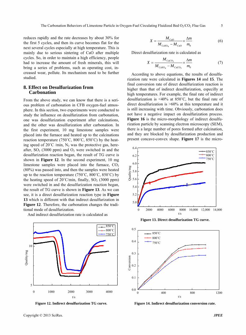
From the above study, we can know that there is a seri-ous problem of carbonation in CFB oxygen-fuel atmos-phere. In this section, two experiments were conducted to study the influence on desulfurization from carbonation, one was desulfurization experiment after calcinations, and the other was desulfurization after carbonation. In the first experiment, 10 mg limestone samples were placed into the furnace and heated up to the calcinations reaction temperature (750˚C, 800˚C, 850˚C) by the heat-ing speed of 20˚C /min, N2 was the protective gas, here-after, SO2 (3000 ppm) and O2 were switched in and the desulfurization reaction began, the result of TG curve is shown in Figure 12. In the second experiment, 10 mg limestone samples were placed into the furnace, CO2 (80%) was passed into, and then the samples were heated up to the reaction temperature (750˚C, 800˚C, 850˚C) by the heating speed of 20˚C/min, finally, SO2 (3000 ppm) were switched in and the desulfurization reaction began, the result of TG curve is shown in Figure 13. As we can see, it is a direct desulfurization reaction type in Figure 13 which is different with that indirect desulfurization in Figure 12. Therefore, the carbonation changes the tradi-tional mode of desulfurization.
And indirect desulfurization rate is calculated as
850˚C800˚C750˚C
10
5
Qua
lity/
mg
0 1000 2000 3000 4000
t/s
Figure 12. Indirect desulfurization TG curve.
4
CaO
CaSO CaO 0
M mX
M M m
(6)
Direct desulfurization rate is calculated as
3
4 3
CaCO
CaSO CaCO 0
M mX
M M m
(7)
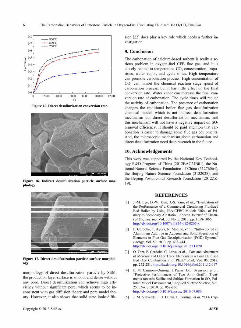
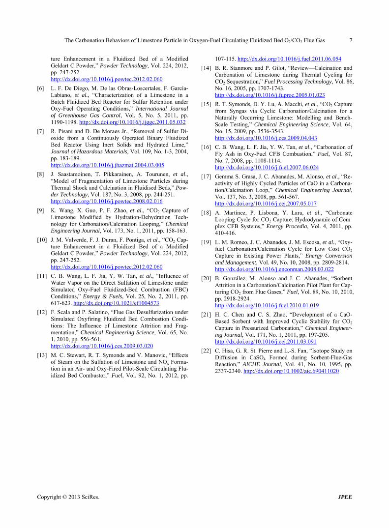
According to above equations, the results of desulfu-rization rate were calculated in Figures 14 and 15. The final conversion rate of direct desulfurization reaction is higher than that of indirect desulfurization, especilly at high temperatures. For example, the final rate of indirect desulfurization is <40% at 850˚C, but the final rate of direct desulfurization is >60% at this temperature and it is still increasing with time. Obviously, carbonation does not have a negative impact on desulfurization process. Figure 16 is the micro-morphology of indirect desulfu-rization particle by scanning electron microscopy (SEM), there is a large number of pores formed after calcination, and they are blocked by desulfurization production and present concave-convex shape. Figure 17 is the micro-
850˚C800˚C750˚C
6.4
6.2
6.0
5.8
5.6
5.4
5.2
5.0
Qua
lity/
mg
0 2000 4000 6000 8000 10,000 12,000 14,000t/s
Figure 13. Direct desulfurization TG curve.
850˚C
800˚C
750˚C
0.5
0.4
0.3
0.2
0.1
0.0
Con
vers
ion
0 400 800 1200t/s
Figure 14. Indirect desulfurization conversion rate.
Copyright © 2013 SciRes. JPEE
The Carbonation Behaviors of Limestone Particle in Oxygen-Fuel Circulating Fluidized Bed O2/CO2 Flue Gas 6
850˚C 800˚C 750˚C
0.8
0.7
0.6
0.5
0.4
0.3
0.2
0.1
0.0
Con
vers
ion
0 2000 4000 6000 8000 10,000 12,000t/s
Figure 15. Direct desulfurization conversion rate.
Figure 16. Indirect desulfurization particle surface mor- phology.
Figure 17. Direct desulfurization particle surface morphol- ogy.
morphology of direct desulfurization particle by SEM, the production layer surface is smooth and dense without any pore. Direct desulfurization can achieve high effi-ciency without significant pore, which seems to be in-consistent with gas diffusion theory and pore model the-ory. However, it also shows that solid state ionic diffu-
sion [22] does play a key role which needs a further in-vestigation.
9. Conclusion
The carbonation of calcium-based sorbent is really a se-rious problem in oxygen-fuel CFB flue gas, and it is closely related to temperature, CO2 concentration, impu-rities, water vapor, and cycle times. High temperature can promote carbonation process. High concentration of CO2 can inhibit the chemical reaction stage speed of carbonation process, but it has little effect on the final conversion rate. Water vapor can increase the final con-version rate of carbonation. The cycle times will reduce the activity of carbonation. The presence of carbonation changes the traditional boiler flue gas desulfurization chemical model, which is not indirect desulfurization mechanism but direct desulfurization mechanism, and this mechanism will not have a negative impact on SO2 removal efficiency. It should be paid attention that car- bonation is easier to damage some flue gas equipments. And, the microscopic mechanism about carbonation and direct desulfurization need deep research in the future.
10. Acknowledgements
This work was supported by the National Key Technol-ogy R&D Program of China (2012BAC24B01), the Na-tional Natural Science Foundation of China (51276064), the Beijing Nature Science Foundation (3132028), and the Beijing Postdoctoral Research Foundation (2012ZZ- 19).
REFERENCES [1] J.-M. Lee, D.-W. Kim, J.-S. Kim, et al., “Evaluation of
the Performance of a Commercial Circulating Fluidized Bed Boiler by Using IEA-CFBC Model: Effect of Pri- mary to Secondary Air Ratio,” Korean Journal of Chemi- cal Engineering, Vol. 30, No. 5, 2013, pp. 1058-1066. http://dx.doi.org/10.1007/s11814-012-0206-x
[2] P. Cordoba, C. Ayora, N. Moreno, et al., “Influence of an Aluminium Additive in Aqueous and Solid Speciation of Elements in Flue Gas Desulphurisation (FGD) System,” Energy, Vol. 50, 2013, pp. 438-444. http://dx.doi.org/10.1016/j.energy.2012.11.020
[3] O. Font, P. Cordoba, C. Leiva, et al., “Fate and Abatement of Mercury and Other Trace Elements in a Coal Fluidised Bed Oxy Combustion Pilot Plant,” Fuel, Vol. 95, 2012, pp. 272-281. http://dx.doi.org/10.1016/j.fuel.2011.12.017
[4] P. M. Carmona-Quiroga, I. Panas, J.-E. Svensson, et al., “Protective Performances of Two Anti- Graffiti Treat- ments towards Sulfite and Sulfate Formation in SO2 Pol- luted Model Environment,” Applied Surface Science, Vol. 257, No. 3, 2010, pp. 852-856. http://dx.doi.org/10.1016/j.apsusc.2010.07.080
[5] J. M. Valverde, F. J. Duran, F. Pontiga, et al. “CO2 Cap-
Copyright © 2013 SciRes. JPEE
The Carbonation Behaviors of Limestone Particle in Oxygen-Fuel Circulating Fluidized Bed O2/CO2 Flue Gas
Copyright © 2013 SciRes. JPEE
7
ture Enhancement in a Fluidized Bed of a Modified Geldart C Powder,” Powder Technology, Vol. 224, 2012, pp. 247-252. http://dx.doi.org/10.1016/j.powtec.2012.02.060
[6] L. F. De Diego, M. De las Obras-Loscertales, F. Garcia- Labiano, et al., “Characterization of a Limestone in a Batch Fluidized Bed Reactor for Sulfur Retention under Oxy-Fuel Operating Conditions,” International Journal of Greenhouse Gas Control, Vol. 5, No. 5, 2011, pp. 1190-1198. http://dx.doi.org/10.1016/j.ijggc.2011.05.032
[7] R. Pisani and D. De Moraes Jr., “Removal of Sulfur Di- oxide from a Continuously Operated Binary Fluidized Bed Reactor Using Inert Solids and Hydrated Lime,” Journal of Hazardous Materials, Vol. 109, No. 1-3, 2004, pp. 183-189. http://dx.doi.org/10.1016/j.jhazmat.2004.03.005
[8] J. Saastamoinen, T. Pikkarainen, A. Tourunen, et al., “Model of Fragmentation of Limestone Particles during Thermal Shock and Calcination in Fluidised Beds,” Pow- der Technology, Vol. 187, No. 3, 2008, pp. 244-251. http://dx.doi.org/10.1016/j.powtec.2008.02.016
[9] K. Wang, X. Guo, P. F. Zhao, et al., “CO2 Capture of Limestone Modified by Hydration-Dehydration Tech- nology for Carbonation/Calcination Looping,” Chemical Engineering Journal, Vol. 173, No. 1, 2011, pp. 158-163.
[10] J. M. Valverde, F. J. Duran, F. Pontiga, et al., “CO2 Cap- ture Enhancement in a Fluidized Bed of a Modified Geldart C Powder,” Powder Technology, Vol. 224, 2012, pp. 247-252. http://dx.doi.org/10.1016/j.powtec.2012.02.060
[11] C. B. Wang, L. F. Jia, Y. W. Tan, et al., “Influence of Water Vapor on the Direct Sulfation of Limestone under Simulated Oxy-Fuel Fluidized-Bed Combustion (FBC) Conditions,” Energy & Fuels, Vol. 25, No. 2, 2011, pp. 617-623. http://dx.doi.org/10.1021/ef1004573
[12] F. Scala and P. Salatino, “Flue Gas Desulfurization under Simulated Oxyfiring Fluidized Bed Combustion Condi- tions: The Influence of Limestone Attrition and Frag- mentation,” Chemical Engineering Science, Vol. 65, No. 1, 2010, pp. 556-561. http://dx.doi.org/10.1016/j.ces.2009.03.020
[13] M. C. Stewart, R. T. Symonds and V. Manovic, “Effects of Steam on the Sulfation of Limestone and NOx Forma- tion in an Air- and Oxy-Fired Pilot-Scale Circulating Flu- idized Bed Combustor,” Fuel, Vol. 92, No. 1, 2012, pp.
107-115. http://dx.doi.org/10.1016/j.fuel.2011.06.054
[14] B. R. Stanmore and P. Gilot, “Review—Calcination and Carbonation of Limestone during Thermal Cycling for CO2 Sequestration,” Fuel Processing Technology, Vol. 86, No. 16, 2005, pp. 1707-1743. http://dx.doi.org/10.1016/j.fuproc.2005.01.023
[15] R. T. Symonds, D. Y. Lu, A. Macchi, et al., “CO2 Capture from Syngas via Cyclic Carbonation/Calcination for a Naturally Occurring Limestone: Modelling and Bench- Scale Testing,” Chemical Engineering Science, Vol. 64, No. 15, 2009, pp. 3536-3543. http://dx.doi.org/10.1016/j.ces.2009.04.043
[16] C. B. Wang, L. F. Jia, Y. W. Tan, et al., “Carbonation of Fly Ash in Oxy-Fuel CFB Combustion,” Fuel, Vol. 87, No. 7, 2008, pp. 1108-1114. http://dx.doi.org/10.1016/j.fuel.2007.06.024
[17] Gemma S. Grasa, J. C. Abanades, M. Alonso, et al., “Re- activity of Highly Cycled Particles of CaO in a Carbona- tion/Calcination Loop,” Chemical Engineering Journal, Vol. 137, No. 3, 2008, pp. 561-567. http://dx.doi.org/10.1016/j.cej.2007.05.017
[18] A. Martínez, P. Lisbona, Y. Lara, et al., “Carbonate Looping Cycle for CO2 Capture: Hydrodynamic of Com- plex CFB Systems,” Energy Procedia, Vol. 4, 2011, pp. 410-416.
[19] L. M. Romeo, J. C. Abanades, J. M. Escosa, et al., “Oxy- fuel Carbonation/Calcination Cycle for Low Cost CO2 Capture in Existing Power Plants,” Energy Conversion and Management, Vol. 49, No. 10, 2008, pp. 2809-2814. http://dx.doi.org/10.1016/j.enconman.2008.03.022
[20] B. González, M. Alonso and J. C. Abanades, “Sorbent Attrition in a Carbonation/Calcination Pilot Plant for Cap- turing CO2 from Flue Gases,” Fuel, Vol. 89, No. 10, 2010, pp. 2918-2924. http://dx.doi.org/10.1016/j.fuel.2010.01.019
[21] H. C. Chen and C. S. Zhao, “Development of a CaO- Based Sorbent with Improved Cyclic Stability for CO2 Capture in Pressurized Carbonation,” Chemical Engineer- ing Journal, Vol. 171, No. 1, 2011, pp. 197-205. http://dx.doi.org/10.1016/j.cej.2011.03.091
[22] C. Hisa, G. R. St. Pierre and L.-S. Fan, “Isotope Study on Diffusion in CaSO4 Formed during Sorbent-Flue-Gas Reaction,” AICHE Journal, Vol. 41, No. 10, 1995, pp. 2337-2340. http://dx.doi.org/10.1002/aic.690411020