The Canadian and Australian F/A-18 International Follow-On ...
17
ICAS 2002 CONGRESS 06.1 The Canadian and Australian F/A-18 International Follow-On Structural Test Project D. L. Simpson Institute for Aerospace Research National Research Council of Canada Ottawa, Ontario, Canada N. Landry Directorate of Technical Airworthiness Department of National Defence Ottawa, Ontario, Canada Jean Roussel Military Aviation Services Bombardier Aerospace Defence Services Mirabel, Quebec, Canada L. Molent A. D. Graham Defence Science and Technology Organisation Aeronautical and Maritime Research Laboratory Airframe and Engines Division Melbourne, Australia N. Schmidt Directorate General of Technical Airworthiness RAAF Williams, Laverton, Australia Keywords: aircraft, structural testing, spectrum, F/A-18, IFOSTP Abstract Both the Royal Australian Air Force (RAAF) and Canadian Forces (CF) operate the Boeing F/A-18 in a non-aircraft carrier role. This has resulted in operational usage quite different to that specified by the United States Navy (USN) for airframe certification. Given similarities in operational usage, airframe configuration and airframe management philosophies, the RAAF and CF embarked on a significant collaborative project known as the International Follow-On Structural Test Project (IFOSTP). IFOSTP consists of three separate and major full-scale fatigue tests supported by flight trials and load development programs. This paper summarizes IFOSTP, indicating significant new developments in the art of fatigue testing and highlights the benefits of collaboration. 1 Introduction Between the Canadian Forces (CF) and the Royal Australian Air Force (RAAF), 210 F/A- 18 aircraft were purchased from McDonnell Douglas with deliveries between 1982 and 1990. Both countries operate the aircraft in similar roles that are very different to its intended role in the USN. The certification test was performed for a carrier based operation with a USN specified design usage spectrum that is significantly less severe for most primary structural elements, compared with that of the RAAF and CF. Additionally, there were significant configuration differences between the RAAF and CF fleets and the certification test article. These issues led to concerns over the useful life of the airframe. Given similar aircraft structural integrity management philosophies, both parties realized that major benefits could be realised through collaboration. In particular, as the basis for both countries’ structural integrity management, a fatigue test should be conducted under representative CF/RAAF loading, thus IFOSTP was born. This highly technical project fostered many initiatives in the field of full-scale fatigue testing. Many of these were only feasible due to the collaborative nature of IFOSTP. This paper summaries some of novel test developments and benefits derived from this collaborative project. 2 International Follow-On Structural Test Project The IFOSTP is a collaborative program between the RAAF and the CF and is the most
Transcript of The Canadian and Australian F/A-18 International Follow-On ...

ICAS 2002 CONGRESS
06.1
The Canadian and Australian F/A-18 International Follow-On Structural Test Project
D. L. Simpson
Institute for Aerospace Research National Research Council of Canada
Ottawa, Ontario, Canada
N. Landry Directorate of Technical Airworthiness
Department of National Defence Ottawa, Ontario, Canada
Jean Roussel
Military Aviation Services Bombardier Aerospace Defence Services Mirabel,
Quebec, Canada
L. Molent A. D. Graham
Defence Science and Technology Organisation
Aeronautical and Maritime Research Laboratory
Airframe and Engines Division Melbourne, Australia
N. Schmidt
Directorate General of Technical Airworthiness
RAAF Williams, Laverton, Australia
Keywords: aircraft, structural testing, spectrum, F/A-18, IFOSTP
Abstract Both the Royal Australian Air Force (RAAF) and Canadian Forces (CF) operate the Boeing F/A-18 in a non-aircraft carrier role. This has resulted in operational usage quite different to that specified by the United States Navy (USN) for airframe certification. Given similarities in operational usage, airframe configuration and airframe management philosophies, the RAAF and CF embarked on a significant collaborative project known as the International Follow-On Structural Test Project (IFOSTP). IFOSTP consists of three separate and major full-scale fatigue tests supported by flight trials and load development programs. This paper summarizes IFOSTP, indicating significant new developments in the art of fatigue testing and highlights the benefits of collaboration. 1 Introduction
Between the Canadian Forces (CF) and the Royal Australian Air Force (RAAF), 210 F/A-18 aircraft were purchased from McDonnell Douglas with deliveries between 1982 and 1990. Both countries operate the aircraft in similar roles that are very different to its intended role in the USN. The certification test
was performed for a carrier based operation with a USN specified design usage spectrum that is significantly less severe for most primary structural elements, compared with that of the RAAF and CF. Additionally, there were significant configuration differences between the RAAF and CF fleets and the certification test article. These issues led to concerns over the useful life of the airframe. Given similar aircraft structural integrity management philosophies, both parties realized that major benefits could be realised through collaboration. In particular, as the basis for both countries’ structural integrity management, a fatigue test should be conducted under representative CF/RAAF loading, thus IFOSTP was born. This highly technical project fostered many initiatives in the field of full-scale fatigue testing. Many of these were only feasible due to the collaborative nature of IFOSTP. This paper summaries some of novel test developments and benefits derived from this collaborative project.
2 International Follow-On Structural Test Project
The IFOSTP is a collaborative program between the RAAF and the CF and is the most

Simpson, Molent, Landry, Graham, Roussel, Schmidt
06.2
significant item related to the structural lifing policy and life cycle management of the two fleets. From the analysis of initial usage, it was determined that the aircraft were accumulating fatigue damage faster than predicted by the design assumptions. Consequently, it was determined that on average, only two thirds of the initial required life of the aircraft could be achieved without additional certification testing. This had immense operational and economic implications.
This common experience was initially discussed during meetings of The Technical Cooperation Program (TTCP) HTP-3 Structural Integrity Panel meetings from which came a decision in principle to proceed with a collaborative program of more representative testing. Discussions were held from which a bi-lateral agreement [1] between Australia and Canada was reached to perform a series of full-scale tests on the F/A-18 aircraft. This decision was based on operational, economic and technical considerations. Both air forces were keen to define the structural cost of ownership drivers and structural life of type so that informed decisions could be made on structural integrity management and capability replacement options.
The airframe had been the subject of several manufacturers’ fatigue tests but these were evaluated as being not fully representative for the following reasons: • both the CF and RAAF usage was
significantly different than that assumed for design;
• the differences in configuration between the original manufacturer’s test articles and the CF/RAAF aircraft are significant;
• many components had been re-designed and incorporated based on analysis without verification testing;
• the USN approach to certification testing using a severe spectrum derived from the worst “point-in-the-sky (PITS)” approach and a scatter factor of two, were not consistent with the CF and RAAF airworthiness policies;
• the manufacturer’s fatigue testing of the aft fuselage had considered the aerodynamic buffeting of the aft fuselage and empennage through the application of quasi-static loading;
• the manufacturer’s fatigue testing of the wing had not considered aerodynamic buffeting of the outer wing, aileron and trailing edge flap; and,
• damage tolerance and fail-safety (including residual strength) had not been considered in the manufacturer’s testing. The basis of IFOSTP was that a
representative test might allow increased service life and more cost effective maintenance and repair decisions through the elimination of conservative interpretations of the non-representative tests. IFOSTP consists of three major full-scale fatigue tests, and supporting stand alone centre fuselage wing carry-through bulkhead tests. The centre fuselage test (designated FT55) and the wing test (FT245) are being conducted in Canada whilst the aft fuselage and empennage test (FT46) is being conducted in Australia. The test spectra are a compromise between the two fleets and are considered realistic and representative of in-service usage. In support of these tests, both countries have conducted a series of comprehensive flight trials. These data were used, in conjunction with on-board recorded data from fleet aircraft, computational fluid dynamics and wind tunnel testing to develop the test loads. The agreed objectives of the program are: • determine the economic life, and in the
process, the safe life of the major structural components under a spectrum representative of CF/RAAF operations;
• where possible, obtain crack growth data to support management on a safety by inspection basis;
• validate modifications and repairs; and • establish an engineering database for life-
cycle management through to retirement.

The Canadian and Australian F/A-18 International Follow-On Structural Test Project
06.3
2.1 Partnership Arrangements
The work share of the IFOSTP was defined such that there is no financial obligation on either participant towards the other. The general principle was adopted that the results of the major tests performed by the two countries are of equal value in terms of the aircraft fleet management and economic life determination and results were to be shared without restrictions between the two countries. Within this concept, the RAAF is responsible for the testing of the aft fuselage and empennage of the aircraft and the CF is responsible for the testing of the forward/centre fuselage and wings. The project definition document [1] provided some guidelines that were used to define the detailed test plans and approach to spectrum development. Some highlights of these guidelines were as follows: • test project must be flexible such that each
country could use the results for determining the safe life, economic life and engineering data base relevant to its fleet;
• test structures should be representative of the majority of the RAAF/CF fleet;
• loading spectra representing RAAF and CF operational/training usage will be used with combined dynamic and manoeuvre loading where applicable;
• loads to be applied are to be supported by flight test data;
• airworthy repairs will be incorporated and validated by continued testing;
• for safety of flight structure, flaws will be allowed to grow naturally within pre-defined limits; and
• at the completion of the test, additional information will be obtained by residual strength/stiffness testing and a teardown.
National project managers were appointed from the CF and RAAF with responsibilities for the administration, supervision and technical coordination of the national projects as well as coordinating the international interactions.
In Australia, the test is being performed at the Aeronautical and Maritime Research Laboratory (AMRL), which is part of the Defence Science and Technology Organisation. In Canada, it was decided that two tests would be performed, one on the centre/forward fuselage and another on the wing. This was done primarily for schedule reasons as the immediate requirement was to obtain valid test information on the life limiting centre fuselage and by de-coupling the wing test from the fuselage, the test results would be available sooner. Table 1 identifies the test agencies and their responsibilities under IFOSTP.
National Research Council of Canada Institute for Aerospace Research NRC/IAR)
• Test Spectrum Development • Wing Testing • Advanced Repair Development
Bombardier Aerospace
Defence Services (BA-DS)
• Generation of Balanced Loads for Fuselage and Wing Tests
• Centre/Forward Fuselage Testing • Engineering and Maintenance Support
- Wing Test
Australian Aeronautical and Maritime Research Laboratories (AMRL)
• Generation of Aft Fuselage Loads • Aft Fuselage Testing • Bare Bulkhead Testing
Table 1: Test agency responsibilities
In addition to the test agencies, each country supported the loads development process through extensive flight testing, wind tunnel testing and CFD analyses. Flight tests were used judiciously to provide timely data to the loads development efforts required at the time regardless of the test agency. A total of 7 flight test programs have been performed with over

Simpson, Molent, Landry, Graham, Roussel, Schmidt
06.4
1200 parameters recorded during more than 160 missions [2, 3].
3 CF-RAAF Spectrum Selection
The development of the test spectra was a major challenge. Firstly, this was the first attempt at generating a spectrum based on in-service measured usage data for an aircraft with active control technology coupled with a digital flight control system. This added complexity to quantifying usage since there are additional sensitivities to secondary flight parameters used by the flight control algorithms. The local stress histories at critical areas of the aircraft are not only dependent on the actual manoeuvre flown but also on the speed and altitude (or PITS) of the manoeuvre. Secondly, although there were similarities in the higher order usage statistics, there were significant differences in the way the RAAF and CF operated the aircraft, particularly in the speed/altitude distributions and store configurations. These differences, because of the sensitivity of the flight control system, required careful consideration and judicious compromise to meet both air force’s objectives. Note that two spectra were required for the aft fuselage test due to a post-production configuration change that significantly altered the aft fuselage and empennage buffet damage severity. The general approach to the development of the spectrum was to bias its overall severity towards the most damaging usage in the fleets which in practice meant the spectrum would be based on the average usage of the harshest squadron. The use of an “average” spectrum was a significant departure from the USN design approach that strongly biased the design spectrum towards a severe spectrum. However, in comparison, the USN “severe” spectrum, was not as severe as the CF and RAAF “average” spectrum. Parallel usage data reduction programs were initiated to define the CF and RAAF usage. Canada analysed data from all operational and training squadrons (4 aircraft
each) to determine the spectral content on a squadron by squadron basis. Additional aircraft from the most severe squadron were selected for data reduction. The end result was a set of usage statistics that represented the average of the harshest CF squadron. This process was followed twice: once for the pre-LEX period and again for the post-LEX period. The RAAF produced similar statistics and then selected an aircraft matching their usage statistics to derive the spectra for the pre- and post-lex periods. In selecting the aircraft, attention was paid to the serviceability and response of the empennage strain gauges because their recorded readings were used directly by the Australian loads development process. The RAAF and CF spectra were compared analytically and by representative coupon testing and from this work, final test spectra were defined. Hewitt et al. [3] provides an excellent discussion of the issues involved in spectrum determination for the F/A-18 and Noll [4] discusses the impact of active control technology on structural integrity.
3.1 Usage Monitoring
All F/A-18 aircraft are fitted with a Maintenance Signal Data Recording System (MSDRS). The MSDRS was developed to provide fatigue usage, flight incident records, engine usage data and associated maintenance data. Components of the system comprise an on-board processor, strain gauges and a data recorder that writes to a magnetic tape cartridge. A ground station is used to strip the data from the cartridges and make it available for engineering use. The strain gauges were located to respond primarily to root bending moment for the wing root, wing fold, vertical fins and horizontal stabilators.
Various parameters are grouped together in MSDRS messages and identified by record codes. Each block of data containing a header is called an Air Data File (ADF). The ADF header contains pilot identification, mission type for each flight, aircraft tail number, date of ADF creation, mission computer load number,
The Canadian and Australian F/A-18 International Follow-On Structural Test Project
06.5
base ID and the airframe hours. Thus it was possible to choose representative missions to construct the required operational usage statistics.
3.2 Time History Characterisation
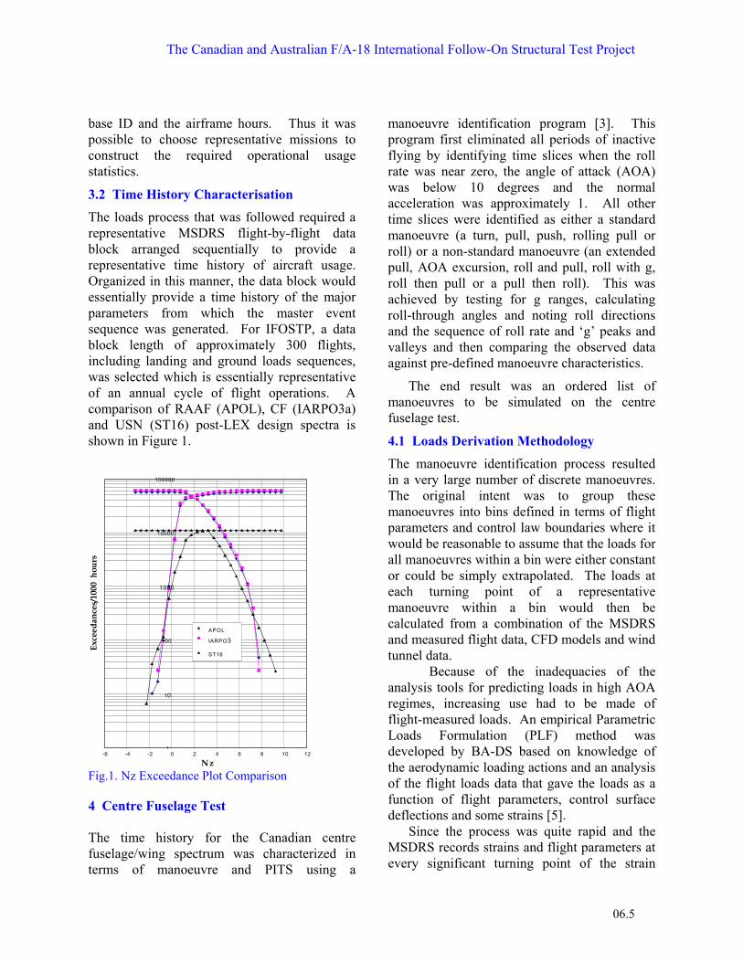
The loads process that was followed required a representative MSDRS flight-by-flight data block arranged sequentially to provide a representative time history of aircraft usage. Organized in this manner, the data block would essentially provide a time history of the major parameters from which the master event sequence was generated. For IFOSTP, a data block length of approximately 300 flights, including landing and ground loads sequences, was selected which is essentially representative of an annual cycle of flight operations. A comparison of RAAF (APOL), CF (IARPO3a) and USN (ST16) post-LEX design spectra is shown in Figure 1.
1
10
100
1000
10000
100000
-6 -4 -2 0 2 4 6 8 10 12
Nz
Exce
edan
ces/
1000
hou
rs
APOL
IARPO3aST16
Fig.1. Nz Exceedance Plot Comparison 4 Centre Fuselage Test The time history for the Canadian centre fuselage/wing spectrum was characterized in terms of manoeuvre and PITS using a
manoeuvre identification program [3]. This program first eliminated all periods of inactive flying by identifying time slices when the roll rate was near zero, the angle of attack (AOA) was below 10 degrees and the normal acceleration was approximately 1. All other time slices were identified as either a standard manoeuvre (a turn, pull, push, rolling pull or roll) or a non-standard manoeuvre (an extended pull, AOA excursion, roll and pull, roll with g, roll then pull or a pull then roll). This was achieved by testing for g ranges, calculating roll-through angles and noting roll directions and the sequence of roll rate and ‘g’ peaks and valleys and then comparing the observed data against pre-defined manoeuvre characteristics.
The end result was an ordered list of manoeuvres to be simulated on the centre fuselage test.
4.1 Loads Derivation Methodology
The manoeuvre identification process resulted in a very large number of discrete manoeuvres. The original intent was to group these manoeuvres into bins defined in terms of flight parameters and control law boundaries where it would be reasonable to assume that the loads for all manoeuvres within a bin were either constant or could be simply extrapolated. The loads at each turning point of a representative manoeuvre within a bin would then be calculated from a combination of the MSDRS and measured flight data, CFD models and wind tunnel data.
Because of the inadequacies of the analysis tools for predicting loads in high AOA regimes, increasing use had to be made of flight-measured loads. An empirical Parametric Loads Formulation (PLF) method was developed by BA-DS based on knowledge of the aerodynamic loading actions and an analysis of the flight loads data that gave the loads as a function of flight parameters, control surface deflections and some strains [5].
Since the process was quite rapid and the MSDRS records strains and flight parameters at every significant turning point of the strain

Simpson, Molent, Landry, Graham, Roussel, Schmidt
06.6
gauges and ‘g’, the option existed of calculating loads for every significant turning point for the centre fuselage spectrum. The only exception to this was for some symmetric, high wing torque, low wing root bending moment cases where the torque peak was not quite coincident with any strain trigger. Binning was therefore not required and the manoeuvre identification was only used to eliminate periods of inactive flying.
4.2 Ground Loads Sequences
Based on a comparative damage approach, it was determined that the only significant ground based loads that needed to be considered for the IFOSTP test spectrum were the landing events and main landing gear maintenance cycling.
4.3 Landing Events
The USN design spectrum was based on unflared landings on an aircraft carrier. Both the CF and RAAF fleets are land based and used flared landings which are significantly less damaging. However, since the MSDRS system only records the maximum descent velocity in the two seconds prior to touchdown, a representative sink speed spectrum needed to be derived. A landing loads spectrum was developed by first obtaining a relationship between the actual sink speed at touchdown, as recorded by a photogrammetric survey, and the MSDRS recorded sink speed [6]. The MSDRS sink speed data for the selected squadron and the above relationship were used to define a distribution of sink speeds for the spectrum. Typical sequences, obtained from a landing loads survey conducted by the CF, which corresponded to selected ranges of sink speeds were then used to develop the landing load sequences.
4.4 Gear Cycle Frequencies
Cycling of the MLG during maintenance was determined to be the only other ground load event of significance to the fatigue life of the centre fuselage. The fleet statistics were matched in the block.
4.5 Centre Fuselage Test System
The centre fuselage test is shown in Figure 2. A total of 64 hydraulic actuators, the two production Main Landing Gear (MLG) retract actuators and six static reaction points are used to load and restrain the aircraft. For each of the load conditions included in the spectrum, actuator loads were derived through an optimisation process to best match the calculated loads over the test section. Typically, wing root shear, bending moments and torque and fuselage vertical bending moments are matched to within 1.5%. Fig. 2. CF-18 IFOSTP Centre Fuselage Full Scale Fatigue Test (FT55) at Bombardier Aerospace Defence Services
4.6 Centre Fuselage Results
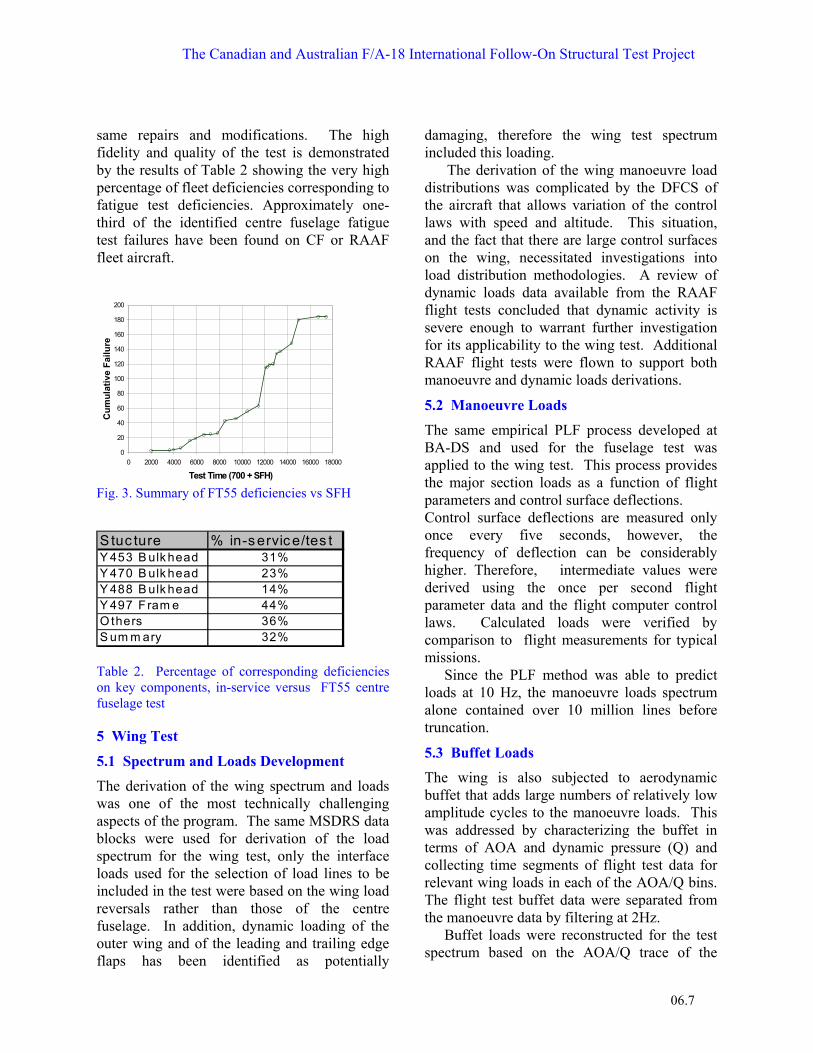
Active cycling was completed when the test specimen had accumulated 17,335 test hours. The specimen is being prepared for residual strength testing and teardown. Accumulation of structural deficiencies against test hours is summarized in Figure 3. A total of 184 deficiencies were recorded during the test. Fifty-two of these were found at the 12,000 spectrum flight hours (SFH) inspection and 32 at the 15,100 SFH inspection [7].
To fulfil project objectives, airworthy repairs were developed and installed whenever this was possible. As a result, over 35 repairs or modifications from FT55 were used directly in the development of fleet modifications within the CF-18 Fleet Structural Life Extension Program. Similarly, the RAAF developed a Structural Refurbishment Program based on the results obtained, taking into consideration the
The Canadian and Australian F/A-18 International Follow-On Structural Test Project
06.7
same repairs and modifications. The high fidelity and quality of the test is demonstrated by the results of Table 2 showing the very high percentage of fleet deficiencies corresponding to fatigue test deficiencies. Approximately one-third of the identified centre fuselage fatigue test failures have been found on CF or RAAF fleet aircraft.
Fig. 3. Summary of FT55 deficiencies vs SFH
Table 2. Percentage of corresponding deficiencies on key components, in-service versus FT55 centre fuselage test 5 Wing Test
5.1 Spectrum and Loads Development
The derivation of the wing spectrum and loads was one of the most technically challenging aspects of the program. The same MSDRS data blocks were used for derivation of the load spectrum for the wing test, only the interface loads used for the selection of load lines to be included in the test were based on the wing load reversals rather than those of the centre fuselage. In addition, dynamic loading of the outer wing and of the leading and trailing edge flaps has been identified as potentially
damaging, therefore the wing test spectrum included this loading.
The derivation of the wing manoeuvre load distributions was complicated by the DFCS of the aircraft that allows variation of the control laws with speed and altitude. This situation, and the fact that there are large control surfaces on the wing, necessitated investigations into load distribution methodologies. A review of dynamic loads data available from the RAAF flight tests concluded that dynamic activity is severe enough to warrant further investigation for its applicability to the wing test. Additional RAAF flight tests were flown to support both manoeuvre and dynamic loads derivations.
5.2 Manoeuvre Loads
The same empirical PLF process developed at BA-DS and used for the fuselage test was applied to the wing test. This process provides the major section loads as a function of flight parameters and control surface deflections. Control surface deflections are measured only once every five seconds, however, the frequency of deflection can be considerably higher. Therefore, intermediate values were derived using the once per second flight parameter data and the flight computer control laws. Calculated loads were verified by comparison to flight measurements for typical missions.
Since the PLF method was able to predict loads at 10 Hz, the manoeuvre loads spectrum alone contained over 10 million lines before truncation.
5.3 Buffet Loads
The wing is also subjected to aerodynamic buffet that adds large numbers of relatively low amplitude cycles to the manoeuvre loads. This was addressed by characterizing the buffet in terms of AOA and dynamic pressure (Q) and collecting time segments of flight test data for relevant wing loads in each of the AOA/Q bins. The flight test buffet data were separated from the manoeuvre data by filtering at 2Hz.
Buffet loads were reconstructed for the test spectrum based on the AOA/Q trace of the
0
20
40
60
80
100
120
140
160
180
200
0 2000 4000 6000 8000 10000 12000 14000 16000 18000
Test Time (700 + SFH)
Cum
ulat
ive
Failu
re
Stuc ture % in-s ervic e/tes tY 453 B ulk head 31%Y 470 B ulk head 23%Y 488 B ulk head 14%Y 497 F ram e 44%O thers 36%S um m ary 32%

Simpson, Molent, Landry, Graham, Roussel, Schmidt
06.8
spectrum flights by selecting a length of buffet data from the database for the appropriate AOA/Q bin and adding it to the previously developed manoeuvre loads. The dynamic loads were captured at 483 Hz, so the addition of buffet to the spectrum increased the number of lines in the spectrum by an order of magnitude. Turbulence loads were developed in a similar manner to buffet loads except that they were limited to very low AOA and low altitude.
5.4 Truncation
This exceeding large load history (approx 8,000,000 lines) had to be truncated. Typically, this process involves the calculation of a stress history at a critical location based on the applied loads followed by both analytical and coupon studies to eliminate non-damaging cycles [8]. For the wing test, there were a number of control points for which there was no way of deriving a stress sequence. Instead, the NRC developed a methodology to truncate on section loads [9].
The NRC used this method to perform a relatively aggressive truncation to the raw spectrum that resulted in a final test spectrum of approximately 154,500 unique load conditions. Because of control system limitations and the time required to optimise and check the actuator loads for so many load conditions, a binning process was used to reduce the number of unique load conditions to less than 50,000. This process grouped similar load conditions into bins and then used one of the load conditions in the bin to represent all the loads in that bin. The full spectrum of 154,500 lines was then re-built using the 50,000 unique conditions. Note that all truncations were evaluated systematically by analysis and by representative test coupon programs to ensure that significant damage was not missed.
5.5 Distributed Loads
For this wing, with large independently controlled control surfaces, it was imperative that the spanwise and chordwise loads distributions be representative. Distributed loads for the full 154,500 load conditions were
developed by BA-DS based on the aircraft weight distribution for the inertia loads, wind tunnel distributions for the aerodynamic loads and optimised force distributions for the dynamic loads. The latter were optimised to give the correct dynamic control point loads and were checked against a number of measured strains and accelerations from the flight test data.
The aerodynamic distribution process used an optimisation process to define the best set of distributed panel loads that matched the wind tunnel distributions and, when integrated, matched the twelve target interface loads (control point loads). Since these target interface loads were predicted from flight parameters and had an associated level of uncertainty, they were allowed to vary within their level of uncertainty during the optimisation process to ensure realistic distributions. The final control point loads for the distributed loads set were therefore slightly different from the original control point loads. Fatigue calculations were performed for the distributed loads sequence to quantify the effects of these changes. Generally, the changes were small, particularly for the most important interface loads. However, there were significant changes for the wing fold and wing root torque load sequences.
When the wing fold and wing root torques were constrained, the optimisation produced unrealistic panel loads on the inner wing box. The major drivers for these torques are the control surface hinge moments, and these were considered to be more reliable than the torques (wing torque is notoriously difficult to measure in a flight test). The decision was therefore made not to constrain the torques during the optimisation process. This decision was subsequently proved correct, when comparisons to flight test strains were made during the initial strain survey.
5.6 Wing Test System
An overall view of the wing test at NRC is shown in Figure 4. The primary test article is the right hand inner and outer wing box.

The Canadian and Australian F/A-18 International Follow-On Structural Test Project
06.9
However, to ensure that loads are introduced into this structure in a representative manner, all loading other than direct loads on the wing surfaces are introduced through representative structure. Thus the wing is mounted on an F/A-18 fuselage and all control surfaces and pylons are representative F/A-18 structure. Loads are introduced via 63 servo-hydraulic actuators. There are 10 on the fuselage, 12 on the three sets of stores, 6 on the left hand stub wing, 2 horizontally and 33 vertically on the right wing and control surfaces. Fig. 4. IFOSTP Wing Test (FT245) at NRC
The actuator loads calculation process for the test wing broke new ground. The conventional process of matching section loads and spanwise distributions resulted in unrealistic test distributions which necessitated the development of a more robust optimisation process that accounted for chordwise distributions (Figures 5, 6 and 7).
The intent of the optimisation was to find a set of actuator loads that result in panel loads that are closest to the input panel loads, thereby minimising differences. The process allowed for a higher weighting of selected panels and also for the fact that, because of the fixed whiffletree geometry, panel loads attached to the same actuator have a fixed load ratio. Each panel was weighted proportionally to the number of pads that attach to a specific actuator. In that way, the larger panel loads are matched most accurately. The panel loads were calculated from the actuator loads and a set of influence coefficients that related the load fraction of each actuator for each panel based on the whiffletree geometry. This new process
resulted in an excellent match to section loads while providing a more realistic pressure distribution.
Fig.5. Aerodynamic panel input load distribution from BA-DS
Fig. 6. Output pressure distribution using conventional section loads optimisation (note unrealistic chordwise distribution)
Fig. 7. Output Pressure Distribution using Panel Loads Optimisation (note fidelity with aerodynamic panel input distribution)
5.7 Control and Data Acquisition System
Test loads are controlled by an MTS Aero-90TM system using digital servo controllers and a Windows based operator interface. The system includes continual end point checking so that

Simpson, Molent, Landry, Graham, Roussel, Schmidt
06.10
the operator is notified if any end points are outside of a defined error limit. Data from 512 strain gauges are recorded and monitored via a high level multiplexed system, while an additional 60 strain gauges and 12 displacements are recorded on a high speed system integral with the controllers. The data acquisition and control systems are fully integrated and allow sophisticated on-line trend monitoring [10].
5.8 Wing Test Status
Active testing initiated in February 2001 and a total of 7498 SFH have been completed as of May 2002. The test goal is 18,700 SFH. Accumulation of test deficiencies against test hours is summarized in Figure 8. A total of 168 deficiencies have been identified. Seventy-one were found during the pre-test inspection. All of these were of a minor nature. At the 3977 SFH major inspection, an additional 39 relatively minor deficiencies were reported for the wing specimen.
0 20 40 60 80
100 120
140
160
180
0 1000 2000 3000 4000 5000 6000 7000 8000Test Time (SFH)
Cum
ulat
ive
Dam
ages
Fou
nd
Fig. 8. Summary of FT245 deficiencies vs SFH.
At 3977 SFH the front spar of the wing was modified with a proposed fleet modification that involved cold working of holes and installation of oversize fasteners in the front spar.
Repairs to the transition structures are a major schedule influence. On the transition structures, which include the control surfaces, fuselage, stub wing, pylons and AIM 9 launcher, there have been 347 deficiencies reported including significant cracking. To mitigate this schedule risk and to reduce repair costs, the centre fuselage transition structure will be replaced after approximately 10,000
hours. Transition control surfaces have also been replaced.
Active testing is to be completed by mid-2005 followed by a residual strength test and a teardown inspection. 6 Aft Fuselage Test The F/A-18 is an extremely manoeuvrable, versatile, high performance fighter/attack aircraft. The inner wing LEX provides fuselage and inner wing lift enabling it to achieve AOA in excess of 60 degrees. The twin vertical tails canted slightly outward exploit the high-energy vortices generated by each LEX to provide good directional stability at these high AOA conditions (Figure 9). Unfortunately, these vortices break down at AOA> 10 degrees, buffeting the structure and exciting the resonant frequencies of the empennage, producing high acceleration levels (Table 3) resulting in high stress levels in key structural components. The problem was so severe that the manufacturer retroactively strengthened the fin attachments by fitting steel cleats and also fitted aerodynamic fences (known as “LEX fences”) to the leading edge extensions to reduce buffet severity.
There is a synergistic interaction between the quasi-static manoeuvre loading and the higher frequency buffet loading with respect to fatigue damage. The general effect is that the buffet cycles are applied at high mean loads, which increases their contribution to fatigue damage. This phenomenon is well understood and the manufacturer attempted to apply representative (i.e. correct mean plus buffet) loads during the aft fuselage structural fatigue compliance tests. Separate dynamic fin tests were performed in which dynamic loads alone were applied to test the upper half of the fins. However, the loads were not applied realistically in terms of frequency and count but rather as calculated resultant loads at the normal quasi-static fatigue test rates. The primary objective of the Australian IFOSTP loading development process was to ensure that FT46 was loaded such that its dynamic response

The Canadian and Australian F/A-18 International Follow-On Structural Test Project
06.11
matched as closely as possible that of an aircraft in flight. To accomplish this, a manoeuvre loading system was required that would not significantly affect the dynamic characteristics of the structure.
Fig.9. Empennage Buffet at High AOA Dynamic Mode AOA
(deg) for Peak Levels
Q (psf) Range for Peak Levels
Approx Freq. (Hz)
Approx Aft Tip Peak Accel.
VT 1st Bending Mode 1
32-36 175-225 16 ± 170 g
VT 1st Torsion Mode 2
24-28 400-500 45 ± 500 g
Stab. 1st Bending 36-39 225-300 12 ± 100 g Stab. 2nd Bending & 1st Torsion1
16-20 350-400 38/46 ± 350 g
Table 3. Empennage Peak Modal Response Characteristics (Note1: Modes are closely coupled and thus the peak response represents the superposition of both.)
Actual modal vibrations were generated at the correct frequencies and simultaneously applied with the corresponding manoeuvre loading [11,12,13,14,15,16]. Australia entered into major programs to develop the test rig and unique loading system, the test loading sequence of manoeuvre and buffet loads, and
equally important, the control systems. A new airframe (less wings, forward fuselage and auxiliaries) was purchased for the test.
6.1 Manoeuvre Load Development
The load sequence was developed to represent actual flight conditions encountered during 250 operational flights [17]. Real manoeuvres are replicated rather than a small set of ideal manoeuvres under a limited range of conditions, as is typically used in the development of a full scale fatigue test design loading spectrum.
The manoeuvre loads comprise aerodynamic and inertia loads. Determination of aerodynamic loads involved flight testing, CFD analyses and an extensive wind tunnel testing program to provide aerodynamic pressure distributions over the aft fuselage and empennage.
At each strain turning point recorded by the on-board MSDRS system in the 250 flight sequence, the primary bending moment of each vertical fin and horizontal stabilator was determined. Flight parameters at each turning point were also determined from the MSDRS data and a 6 DOF flight reconstruction program. An appropriate manoeuvre load distribution was then calculated by a Fatigue Loads Program (FLP) specially developed by AMRL, using measured wind tunnel pressure distributions, inertial mass distributions provided by Boeing and accelerations derived from the enhanced flight parameter data. Other applied loads include engine loads (inertia and thrust), rudder hinge moments, speed brake and ground loads.
6.2 Dynamic Load Development
The strategy behind the development of the buffet loads was to ensure that the test article modal response matched as closely as possible the dynamic behaviour of a service aircraft in flight [13]. If the mode shapes were correctly matched and the response levels at control accelerometers located at the tip of each fin and stabilator matched flight measured accelerations, then representative dynamic load distributions are assumed to exist. Extensive Ground Vibration Testing (GVT) of CF and RAAF fleet aircraft, and of the test article

Simpson, Molent, Landry, Graham, Roussel, Schmidt
06.12
achieved structural dynamic similarity. The test article has been dynamically tuned to respond in the same manner as a fleet aircraft, taking into account the slight effect that the manoeuvre loading system has on modal response. The other crucial requirement was to duplicate the acceleration response levels characteristic of a fleet aircraft for the full 250 flight test sequence. This was achieved by matching the AOA/Q statistics from the fleet MSDRS records since acceleration response levels are a function of AOA and Q.
Over 110 hours of flight testing were undertaken by the CF at AETE (Aircraft Engineering and Test Establishment, Alberta) and by the RAAF at ARDU (Aircraft Research and Development Unit, South Australia), with and without the LEX fence installed, to measure typical vibration response data (strain and acceleration) for the aft fuselage and empennage. Pre LEX fence data from Boeing for the aft fuselage and empennage response were also used. The data from all flight testing was filtered to obtain the response of the critical modes in the 10-20 and 32-52 Hz bands. An aggregate time weighted data base of RMS acceleration levels for the test article dynamic response control points for each AOA/Q region was then developed from the various flight test data sets. This database was then used to develop the FT46 buffet sequences [16].
For every period of flying in the 250 flight test sequence where the AOA exceeded 10 degrees, the AOA and Q were noted and the appropriate number of seconds of buffet in each AOA and Q region were assembled to produce segments of buffet accelerations for each dynamic control point. These acceleration segments were converted into individual shaker drive signals using a process termed ‘system dynamic characterization’. This process links acceleration response to shaker load and yields amplifier drive voltages to produce the dynamic test loading sequences that are necessary to achieve the desired test sequence. A total of 894 separate buffet segments were generated, representing 31,000 seconds of flying with AOA>10 degrees.
6.3 Test System
The test system was developed during a five- year development program utilising ST01, an early centre/aft static test fuselage provided by the USN. The availability of this test article was crucial to the development program, since it enabled the loading and control systems to be developed without risking the FT46 test article.
The essence of the load application system is a unique rolling sleeve pneumatic actuator that has soft spring stiffness and low mass. Using this system, the distributed manoeuvre loads can be applied without affecting the effective stiffness of the empennage components.
Fig. 10. Rolling Sleeve Airbags (Red) and Electromagnetic Shaker (Blue) in Place on the Horizontal Tail
Concurrently, electromagnetic shakers
apply the dynamic loading, while an active reaction control system maintains almost zero displacement of the test article to minimise shaker stroke requirements during high manoeuvre loading. In this manner the significant number of dynamic cycles occurring over the service life of an aircraft can be economically applied to a test article in real time (Figure 10).
Combined closed loop operation of the air springs and hydraulic shakers has been successfully developed. The controller
The Canadian and Australian F/A-18 International Follow-On Structural Test Project
06.13
developed at AMRL controls 67 inter-dependant load channels such that the manoeuvre loads are controlled to within 2% of the required spectrum loads and the mode shapes and frequencies of the main control surfaces are maintained to approximately ±5% of those measured in flight.
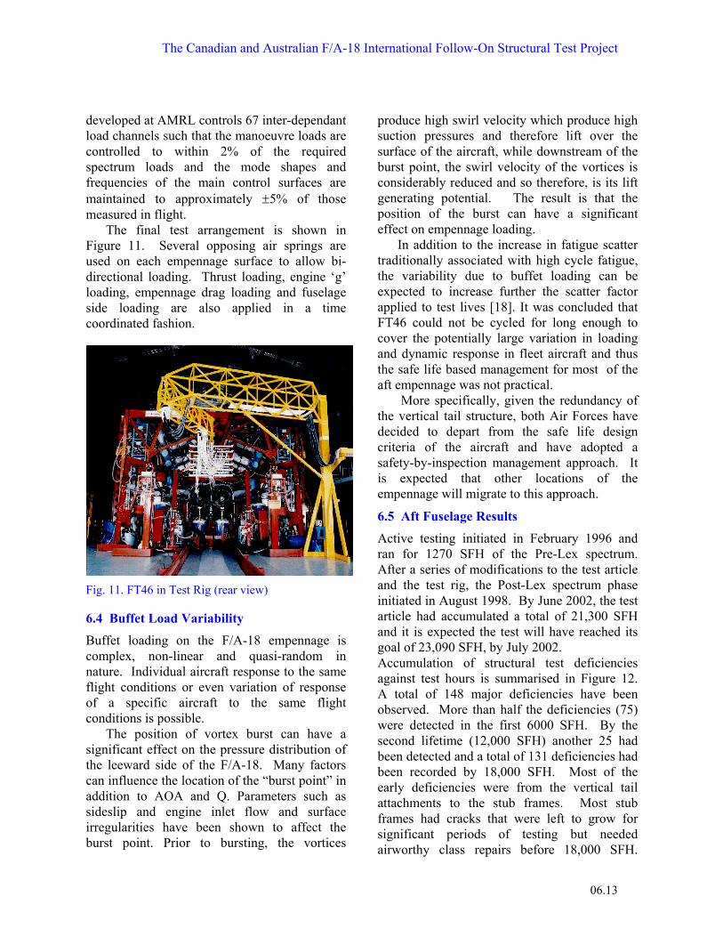
The final test arrangement is shown in Figure 11. Several opposing air springs are used on each empennage surface to allow bi-directional loading. Thrust loading, engine ‘g’ loading, empennage drag loading and fuselage side loading are also applied in a time coordinated fashion.
Fig. 11. FT46 in Test Rig (rear view)
6.4 Buffet Load Variability
Buffet loading on the F/A-18 empennage is complex, non-linear and quasi-random in nature. Individual aircraft response to the same flight conditions or even variation of response of a specific aircraft to the same flight conditions is possible.
The position of vortex burst can have a significant effect on the pressure distribution of the leeward side of the F/A-18. Many factors can influence the location of the “burst point” in addition to AOA and Q. Parameters such as sideslip and engine inlet flow and surface irregularities have been shown to affect the burst point. Prior to bursting, the vortices
produce high swirl velocity which produce high suction pressures and therefore lift over the surface of the aircraft, while downstream of the burst point, the swirl velocity of the vortices is considerably reduced and so therefore, is its lift generating potential. The result is that the position of the burst can have a significant effect on empennage loading.
In addition to the increase in fatigue scatter traditionally associated with high cycle fatigue, the variability due to buffet loading can be expected to increase further the scatter factor applied to test lives [18]. It was concluded that FT46 could not be cycled for long enough to cover the potentially large variation in loading and dynamic response in fleet aircraft and thus the safe life based management for most of the aft empennage was not practical.
More specifically, given the redundancy of the vertical tail structure, both Air Forces have decided to depart from the safe life design criteria of the aircraft and have adopted a safety-by-inspection management approach. It is expected that other locations of the empennage will migrate to this approach.
6.5 Aft Fuselage Results
Active testing initiated in February 1996 and ran for 1270 SFH of the Pre-Lex spectrum. After a series of modifications to the test article and the test rig, the Post-Lex spectrum phase initiated in August 1998. By June 2002, the test article had accumulated a total of 21,300 SFH and it is expected the test will have reached its goal of 23,090 SFH, by July 2002. Accumulation of structural test deficiencies against test hours is summarised in Figure 12. A total of 148 major deficiencies have been observed. More than half the deficiencies (75) were detected in the first 6000 SFH. By the second lifetime (12,000 SFH) another 25 had been detected and a total of 131 deficiencies had been recorded by 18,000 SFH. Most of the early deficiencies were from the vertical tail attachments to the stub frames. Most stub frames had cracks that were left to grow for significant periods of testing but needed airworthy class repairs before 18,000 SFH.

Simpson, Molent, Landry, Graham, Roussel, Schmidt
06.14
Two very significant failures on FT46 were the failure of the most aft support frame (Y598), which needed to be replaced at 17,374 SFH and the failure of both dorsal longerons which were completely severed at 20,997 SFH.
FT46 Structural Deficiencies
020406080
100120140160
020
0040
0060
0080
0010
00012
00014
00016
00018
00020
00022
000
SFH
Cum
ulat
ive
Stru
ctur
al
Def
icie
ncie
s
Figure 12 . Summary of FT46 Deficiencies vs test time
Although the whole of the empennage has not been subjected to a sampling inspection in the fleets, several of these defects have already been observed on some fleet aircraft. Several stub deficiencies have been detected correlating well with the test results. 7 Residual Strength Testing The CF and RAAF defined a residual strength testing (RST) requirement at the completion of fatigue cycling. Due to the maturity of the fleets, operational data were used to assess the maximum loads likely to be encountered by each structural component in the life of the fleet. Based on this determination, appropriate load cases were developed to demonstrate residual strength of the test article at the end of fatigue cycling. The nature of the tests required different approachs to RST for the centre fuselage/wing tests and the aft fuselage test.
For FT55, a review of respective fleet loads was performed. It was determined that the applied RST demonstration load would be 1.2 times the average of the maximum load experienced by each fleet aircraft in its service life to-date. To ensure an added degree of
conservatism, the lowest 10% of the aircraft population was excluded. The FT-245 Wing test will follow a similar process.
For FT46 components, the post-LEX load exceedance data from the test spectrum for each major component was extrapolated using a Gumbel distribution to predict the 1 in 6000 and 1 in 3000 hour values. Gumbel was used as it is an accurate fit for extreme value distributions. It was found that the ratio of loads between the 1 in 6000 and 1 in 3000 hours was approximately 1.2. As the 1.2 factor is commonly specified for use in RSTs, the 1 in 6,000 load case was considered acceptable for the FT46 RST.
8 IFOSTP Achievements
Significant technical innovations were achieved through IFOSTP including:
• the first use of test spectra and load sequences derived directly from operational aircraft with a DFCS employing variable control laws and care-free manoeuvring;
• development of parametric loads formulation (PLF) methodologies that allowed accurate prediction of major section loads for each flight manoeuvre in a very large spectrum. This is an advancement on traditional binning processes;
• development of test load distribution methods for the wing test that accounted for large control surface influences and optimised chordwise as well as the traditional spanwise distributions;
• the first successful simultaneous application of coordinated dynamic and manoeuvre loads representative of flight conditions on multiple components of a full aircraft test structure;
• development of a unique pneumatic “soft spring” manoeuvre loading system including accurate and rapid response controllers;
• design and development of the FT46 controller with 67 actuators of differing type (pneumatic, electromagnetic and hydraulic)

The Canadian and Australian F/A-18 International Follow-On Structural Test Project
06.15
with many channels where actuator interaction (dependency) is significant;
• implementation, on the FT-245 wing test, of a control and data acquisition system with new end point error checking and notification processes including sophisticated on-line trend monitoring;
• advanced the application of bonded composite patches for repair in the area of design development tools as well as the ability to repair highly loaded and cracked structure at geometrically complex components;
• advancement of the field of quantitative fractography that allowed these techniques, with knowledge of local stresses, to be used to accurately predict component time to failure from limited crack growth information;
• application of evolving technology and use of databases to store, retrieve and catalogue IFOSTP information. This has led to several useful fleet management tools;
• parametric load formulation methodologies were developed to accurately predict and recreate load distributions on a continuous time base using operational flight data.
9 Fleet Implications
The three IFOSTP tests and associated research and engineering activities have generated high quality structural integrity information. This information has been pivotal in defining major structural refurbishment activities in the both the RAAF and CF fleets, that will enable each fleet to achieve its respective service retirement date. The information has established life of type limits and has enabled accurate estimation of the cost of structural refurbishment. Whilst other factors also affect whether a weapon system should be replaced early, the IFOSTP information has facilitated the ability to make informed decisions on return on investment for the F-18 weapons system. Further analysis of the results offer the potential to defer new aircraft acquisition costs that are estimated to be worth many billions of dollars.
The results from IFOSTP have yielded unprecedented information to allow the fleet managers the ability to cost and effectively shape their life cycle management programs along with the associated infrastructures. Specifically, they have allowed both countries to change the basis of certification for the aircraft. Although use is still made of information obtained from the Original Equipment Manufacturer’s (OEM) original certification tests, IFOSTP tests are the cornerstone of the F/A-18 structural integrity management for the RAAF and the CF.
The following illustrates how the original IFOSTP objectives were satisfied and the implications for the fleet: • IFOSTP confirmed that the safe life of the
centre fuselage, under CF/RAAF usage and airworthiness policies, was of the order of two thirds of that specified by the OEM. More importantly, IFOSTP identified previously unknown locations subject to cracking;
• to maintain the fleet beyond the two-third safe life, a series of structural inspections, modifications, and repairs are required. These have been incorporated into the test article for performance assessment. In several cases, they were applied early enough to allow the repairs to be certified through testing;
• a clear path for management of the fleet and its associated costs for the next 15-20 years has resulted from IFOSTP. Both countries (with some differences) have developed a cost effective mid-life structural refurbishment programs that minimize the impact on the operational availability of the fleets. Furthermore, the structural modifications can be co-ordinated with the avionics upgrade programs planned for the aircraft. Also, it was determined that a number of centre fuselage replacements would be required. This has allowed the set-up of a centre barrel acquisition and replacement trial well in advance of the required fleet induction time.

Simpson, Molent, Landry, Graham, Roussel, Schmidt
06.16
10 Benefits Of Collaboration
The success of IFOSTP is largely due to the cooperative and collaborative nature of the project. The benefits of this collaboration can be observed on three levels:
Technical
• Free, independent and rigorous review of each country’s processes and results. Because of the nature of the agreement, the CF and RAAF have benefited from having access to a much larger pool of experts;
• As each country focused on a particular aspect of the structure, the testing was conducted with a higher level of fidelity than traditionally possible.
Economic
• Costs were shared between two countries thus making IFOSTP economically possible;
• Flight testing has been a significant aspect of this program and shared facilities has been a major economic benefit;
• Sharing went beyond the requirements for the actual tests. Both countries have shared laboratory testing facilities thus decongesting some laboratories and optimising their utilisation;
Fleet Management
• Linkages related to fleet management have been established between the RAAF and the CF as a result of IFOSTP. The program has allowed the development of robust structural integrity programs for the F/A-18. Fleet information and tools are being freely exchanged between the two countries. The cost of investigating problems and deriving solutions has been much reduced.
11 Collaboration Process
The success of a collaborative program depends mainly on one key factor: trust. This takes a long time to develop and a constant effort to
maintain. For IFOSTP, this was achieved in many ways: • Geography and time zones were a major
challenge to the team. To overcome this, bi-annual Technical Review Meetings (TRM) were held in alternating countries. These events were key to co-ordinating the project and to decision-making. Face-to-face meetings between people performing the work at the facility where the work was being performed built confidence and trust.
• The RAAF and CF placed a Technical Liaison Officer (TLO) in the other participating country with decision-making capability. This was a significant success factor. TLOs kept their respective nations fully briefed on events and ensured that the interest, views, approach of their country were fully considered during the technical discussions and decision-making.
• Key items for international concurrence were identified early in the project and built into the schedule as milestones. This clearly defined the items that each country expected to approve prior to proceeding any further. Video-conferencing used to discuss key points of international concurrence between TRMs.
• A clear damage disposition process was agreed to prior to test start with response time standards.
• To implement this process, Repair Action Teams were formed to ensure rapid decisions on damage disposition including approvals by the RAAF and CF.
12 Conclusion
The F/A-18 full-scale fatigue test project has generated important life cycle management information for the Royal Australian Air Force and the Canadian Forces. The project involved several organisations from each country and proceeded with a high level of cooperation. This enabled a high degree of fidelity to be achieved between the test articles loading environments and that experienced by aircraft in service.

The Canadian and Australian F/A-18 International Follow-On Structural Test Project
06.17
Acknowledgements
The authors gratefully acknowledge that the considerable successes in IFOSTP are due to the innovation, dedication and professionalism of numerous contributors from the following organisations: • Royal Australian Air Force; • Canadian Forces; • National Research Council of Canada; • Australian Defence Science and Technology
Organisation; • CF Aircraft Evaluation and Test
Establishment; • RAAF Aircraft Research and Development
Unit; and • Bombardier Aerospace Defence Services. References [1] The F/A 18 International Follow-On Structural Test
Project (IFOSTP) - Project Definition, 1989. [2] Dietz, AJ and Rider, CK. RAAF Hornet Flight Test
Program to obtain Flight loads Data. Proceedings Australian Aeronautical Conference, Melbourne, September, 1993.
[3] Hewitt, RL, Hiscocks, RJ, and Bernard, G. Loading Spectrum Determination for an Aircraft with a Digital Flight Control System - CF-18 Centre Fuselage Example. Canadian Aeronautics and Space Journal. Vol. 42, No. 1, March 1996.
[4] Noll, T et al., Impact of Active Controls Technology on Structural Integrity. 32nd AIAA Structures, Structural Dynamics and Materials Conference, Baltimore, April 1991.
[5] Simpson, D L. Canadian CF-18 Structural Life Management Program. AGARD-LS-206, 1996.
[6] Jackson, P. Ground Spectrum Definition for the FT-55 Test, National Research Council IAR LTR 0064, 1993.
[7] Davies, JL. IFOSTP FT55 Test Findings and the Way Ahead. 48th CASI Annual Conference, May 2001.
[8] Hewitt, RL and Rutledge, RS. Computer Applications in Full-Scale Aircraft Fatigue Tests. Automation in Fatigue and Fracture: Testing and Analysis, ASTM STP 1231, C. Amzallag, Ed., American Society for Testing and Materials, Philadelphia, 1994, pp.51-69.
[9] Hewitt, RL, Weiss, JP and Nor, PK. Spectrum Editing for a Full-Scale Fatigue Test of a Fighter Aircraft Wing with Buffet Loading. Fatigue Testing and Analysis under Variable Amplitude Loading Conditions, ASTM STP 1439.
[10] Hewitt, RL and Nelson, A. Data Trend Monitoring and End Level Verification – Tools to Reduce Data Storage in Full-Scale Aircraft Fatigue Tests. Applications of Automation Technology in Fatigue and Fracture Testing and Analysis, ASTM STP 1411.
[11] Graham, AD and Watters, KC. Full Scale Fatigue Testing of the F/A-18 Aft Fuselage and Empennage. Proceedings of the Australian Aeronautical Conference, Melbourne Oct. 1989.
[12] Graham, AD, Symons, D, Sherman, D and WGCDR. Eames, T. ARL F/A-18 IFOSTP Full Scale Fatigue Test. Proceedings of Australian Aeronautical Conference, Melbourne, Sep 1993.
[13] Graham, AD, Madley, WB, Rider, CK and Waldman, W. Fatigue Analysis and Testing of Aircraft Subjected to Manoeuvre and Buffet Loads of Comparable Magnitude. Proceedings of the 18th ICAF Symposium, EMAS Limited, Melbourne, Australia, May 1995.
[14] Conser, D, Graham, D, Smith, CJ and Yule, CL. The Application of Dynamic Loads to a Full Scale F/A-18 Fatigue Test Article, Proceedings of ICAS ’96, Sorrento, Italy, 1996.
[15] Graham, D and Madley, W. The Duplication of Flight Loading Conditions on a Full Scale F/A-18 Aft Fuselage and Empennage Test Article, Proceedings of the 19th ICAF Symposium, EMAS Limited, Edinburgh Scotland 1997.
[16] Conser, D, Mouser, C and Waldman, W. Dynamic Load Development and Results for Dynamic Excitation of a Full-Scale F/A-18 Fatigue Test Article. Proceedings of ICAS '98, Melbourne, Sept 98.
[17] Sherman, D and White, P. Development of a Load Sequence for a Fatigue Test of the F/A-18 Aft Fuselage and Empennage. Proc. 2nd ISASTI'96, Jakarta, 1996.
[18] Molent, L., White, P. and Harman, A., “Bounding Structural Durability Due to Buffet Induced Loading”, Proc. Of. 9th Aust. Aerospace Congress, Canberra, 4-8 March 2001.e Plot Comparison