THE CAMAQ PROJECT: A DESIGN-BUILD … CAMAQ PROJECT: A DESIGN-BUILD EXPERIENCE BASED ON ... learning...
13
1 2 nd International CDIO Conference Linköping University Linköping, Sweden 13-14 June 2006 THE CAMAQ PROJECT: A DESIGN-BUILD EXPERIENCE BASED ON A VIRTUAL IMMERSION IN AEROSPACE INDUSTRY PRACTICES C. Fortin, B. Sanschagrin, G. Huet, and S. Gagné Department of Mechanical Engineering, École Polytechnique, Montréal, Canada. ABSTRACT Initiated under the impulse of the Centre for Aerospace Manpower Activities in Quebec (CAMAQ), the Virtual Environment (VE) option represents a unique Conceive- Design-Implement-Operate (CDIO) learning experience for the training of aerospace engineers. This specialization involves coursework such as “Integration of Design and Manufacturing” and “Project Management in Aerospace Engineering”, tied together with a hands-on project and a coherent learning strategy. Each year since 1999, some fifteen students from the VE option participate in a large scale aerospace design effort, named the “CAMAQ project”. Under the guidance of experienced engineers from Bell Helicopter Textron Canada, Bombardier Aerospace, and Pratt & Whitney Canada, the team has to redesign a pylon to retrofit a Pratt & Whitney Canada engine to a Bombardier Aerospace aircraft fuselage. To accomplish their task, they dispose of a dedicated workspace – the CAMAQ laboratory – located at the École Polytechnique (Montreal), which offers a teaching laboratory, meeting rooms, and access to Digital Mock-Up and Product Lifecycle Management technologies. To reflect current practices in the aerospace industry, the information provided by the industrial partners includes: the necessary technical standards from both the airframe and engine partners, the existing CAD parts and assemblies which require modifications for the new engine retrofit, and the certification regulations to complete the proposals for qualification and test programs. This paper outlines how the CAMAQ project successfully trains systems integrators to use standard engineering and manufacturing practices typically deployed in the aerospace industry. The accomplishments of the teams who have participated over the years serve to illustrate the level of knowledge that can be gained by implementing such an ambitious training program. The reported comments made by the aerospace engineers strengthen the position of this high profile educational initiative as a major asset for the new CDIO curriculum implemented at École Polytechnique. 1. INTRODUCTION The defining of the 21 st century aerospace industry has triggered many challenges in terms of training and developing new skills and practices [1]. The emergence of a global competitive market has imposed new demands for aerospace engineering education. A report published by RAND Corporation also questions the industry’s future design capability: “We believe that a declining experience level has been a contributing factor to the problems we observe in many recent aircraft programs” [2]. In order to counter the negative effects of this new trade environment coupled with the aging of the workforce and the availability of new information systems, aerospace companies have singled out the need to implement “wise” teaching strategies. The “CAMAQ project” presented in this paper is one of the most innovative training schemes in the field of aerospace engineering. This hands-on project was developed with the Centre for Aerospace
Transcript of THE CAMAQ PROJECT: A DESIGN-BUILD … CAMAQ PROJECT: A DESIGN-BUILD EXPERIENCE BASED ON ... learning...

1
2nd International CDIO Conference Linköping University Linköping, Sweden
13-14 June 2006
THE CAMAQ PROJECT: A DESIGN-BUILD EXPERIENCE BASED ON A VIRTUAL IMMERSION IN AEROSPACE INDUSTRY PRACTICES
C. Fortin, B. Sanschagrin, G. Huet, and S. Gagné
Department of Mechanical Engineering, École Polytechnique, Montréal, Canada.
ABSTRACT
Initiated under the impulse of the Centre for Aerospace Manpower Activities in Quebec (CAMAQ), the Virtual Environment (VE) option represents a unique Conceive-Design-Implement-Operate (CDIO) learning experience for the training of aerospace engineers. This specialization involves coursework such as “Integration of Design and Manufacturing” and “Project Management in Aerospace Engineering”, tied together with a hands-on project and a coherent learning strategy.
Each year since 1999, some fifteen students from the VE option participate in a large scale aerospace design effort, named the “CAMAQ project”. Under the guidance of experienced engineers from Bell Helicopter Textron Canada, Bombardier Aerospace, and Pratt & Whitney Canada, the team has to redesign a pylon to retrofit a Pratt & Whitney Canada engine to a Bombardier Aerospace aircraft fuselage. To accomplish their task, they dispose of a dedicated workspace – the CAMAQ laboratory – located at the École Polytechnique (Montreal), which offers a teaching laboratory, meeting rooms, and access to Digital Mock-Up and Product Lifecycle Management technologies. To reflect current practices in the aerospace industry, the information provided by the industrial partners includes: the necessary technical standards from both the airframe and engine partners, the existing CAD parts and assemblies which require modifications for the new engine retrofit, and the certification regulations to complete the proposals for qualification and test programs.
This paper outlines how the CAMAQ project successfully trains systems integrators to use standard engineering and manufacturing practices typically deployed in the aerospace industry. The accomplishments of the teams who have participated over the years serve to illustrate the level of knowledge that can be gained by implementing such an ambitious training program. The reported comments made by the aerospace engineers strengthen the position of this high profile educational initiative as a major asset for the new CDIO curriculum implemented at École Polytechnique.
1. INTRODUCTION
The defining of the 21st century aerospace industry has triggered many challenges in terms of training and developing new skills and practices [1]. The emergence of a global competitive market has imposed new demands for aerospace engineering education. A report published by RAND Corporation also questions the industry’s future design capability: “We believe that a declining experience level has been a contributing factor to the problems we observe in many recent aircraft programs” [2].
In order to counter the negative effects of this new trade environment coupled with the aging of the workforce and the availability of new information systems, aerospace companies have singled out the need to implement “wise” teaching strategies. The “CAMAQ project” presented in this paper is one of the most innovative training schemes in the field of aerospace engineering. This hands-on project was developed with the Centre for Aerospace
2
Manpower Activities in Quebec (CAMAQ), IBM, and three large aerospace companies based in the region of Montreal (Canada): Bell Helicopter Textron Canada, Bombardier Aerospace, and Pratt & Whitney Canada. The CAMAQ project selects some fifteen students to redesign a pylon for the retrofit of a Pratt & Whitney Canada engine to a Bombardier Aerospace aircraft fuselage. To accomplish their task, the students dispose of a dedicated workspace, the “CAMAQ laboratory” located at the École Polytechnique (Montreal), which offers access to state of the art Digital Mock-Up (DMU) and Product Lifecycle Management (PLM) technologies.
The CAMAQ project answers at least two major preoccupations outlined by employers in the aerospace industry: it exposes the students to current industrial practices that are not usually experienced by engineers before several years of work in the trade, and it demonstrates the impact of attractive new technologies used by aerospace product development teams. This novel educational experience has become part of the Mechanical Engineering curriculum strategy at École Polytechnique – the Virtual Environment (VE) option – directed towards familiarizing students to virtual product development technologies and methodologies [3].
2. DESCRIPTION OF THE VIRTUAL ENVIRONMENT OPTION
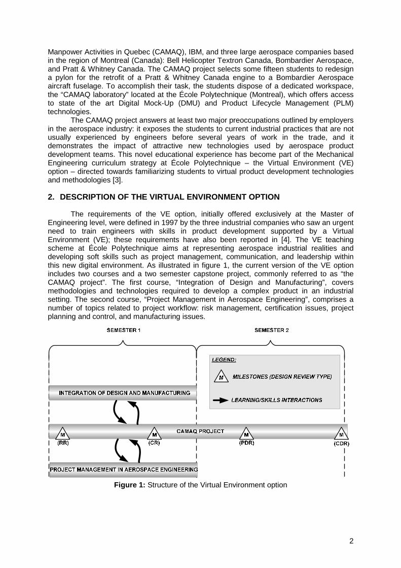
The requirements of the VE option, initially offered exclusively at the Master of Engineering level, were defined in 1997 by the three industrial companies who saw an urgent need to train engineers with skills in product development supported by a Virtual Environment (VE); these requirements have also been reported in [4]. The VE teaching scheme at École Polytechnique aims at representing aerospace industrial realities and developing soft skills such as project management, communication, and leadership within this new digital environment. As illustrated in figure 1, the current version of the VE option includes two courses and a two semester capstone project, commonly referred to as “the CAMAQ project”. The first course, “Integration of Design and Manufacturing”, covers methodologies and technologies required to develop a complex product in an industrial setting. The second course, “Project Management in Aerospace Engineering”, comprises a number of topics related to project workflow: risk management, certification issues, project planning and control, and manufacturing issues.
Figure 1: Structure of the Virtual Environment option

3
2.1. Integration of Design and Manufacturing In the “Integration of Design and Manufacturing” course, which is offered at both
graduate and undergraduate levels, the students learn how to use the VE to support the complete product development process from an Integrated Product Team (IPT) perspective. The course addresses particularly the “Designing (4.4)” and “Implementing (4.5)” criteria of the CDIO syllabus [5], and also the formal introduction of Concurrent Engineering principles and their associated tools [6]. Here, emphasis is placed on the development of technical and business process methodologies to support the development of a complex product with a large team of engineers. The change process and configuration management issues are key elements of the subject. The students learn about product and manufacturing systems, which contain all the data related to the development of a specific product. They also learn how to organise and verify this information using product structures; the engineering Bill Of Material (eBOM) and the manufacturing Bill Of Material (mBOM) are typical product structures used in industry to manage the engineering and manufacturing data on all parts of a product.
During laboratory sessions, the students discover how to build and manage a virtual product using a Computer Aided Design (CAD) system supported by a Product Data Management (PDM) system, in this case CATIA V5 and ENOVIA VPM. The PDM system is also linked to a unique Manufacturing Process Management (MPM) system, Polyplan, which allows students to define and manage the manufacturing plan of a complex product and the associated business rules until final release. The role of this VE course is essentially to create a realistic product development environment within an academic setting.
2.2. Project Management in Aerospace Engineering The “Project Management in Aerospace Engineering” course describes the general
workflow of a project and provides the students with a global insight of aerospace project activities: engineering methodologies used in the aerospace industry, technical inputs and outputs, cost and schedule tracking tools used to successfully plan and complete a project, and certification regulations and processes. One of the aims of these lectures, presented by practicing aerospace engineers, is to introduce the certification process, which is a major constraint in aerospace engineering activities. The students are guided through all the formal procedures that have to be followed in order to certify an aircraft, and pertinent industrial examples are provided for each product development phase. The principles and mechanisms taught during the lectures are then put into practice in the CAMAQ project.
2.3. The CAMAQ project The “CAMAQ project” is a design-build project where a single student group must
retrofit a Pratt & Whitney Canada engine on a Bombardier CRJ700 aircraft. The students involved in the project come from varied cultural and educational backgrounds. The participants are either senior undergraduate students who have registered for the aeronautic option in the Mechanical Engineering department of École Polytechnique, or graduate students enrolled in one of the aerospace engineering Master’s programs offered in the province of Quebec, i.e. Concordia University (Montreal), École Polytechnique (Montreal), École de Technologie Supérieure (Montreal), McGill University (Montreal), Université Laval (Quebec), and Université de Sherbrooke (Sherbrooke).
At the beginning of the first semester, the industrial experts representing each company dispatch all the necessary information required to complete the project: standards, company guidelines, design manuals, aircraft and engine geometries, CAD models, 2D layouts, certification regulations etc. They also present the Statement of Work (SoW) and the Technical Requirements Document (TRD), which define the requirements for the development of the flight ready prototypes including the expected deliverables for each design review.
The project is monitored by 4 formal design reviews (shown by the milestones in figure 1): the Requirements Review (RR), the Concept Review (CR), the Preliminary Design Review (PDR), and the Critical Design Review (CDR). This recalls the aerospace product development control process, composed of formal design reviews [7], which guides the

4
organisation of large engineering teams and verifies the quality of the work achieved. During these meetings, the students are required to submit a detailed report and to formally present the work to the industrial partners who will asses the progress and approve important issues, in collaboration with the teaching staff coaching the project team.
During the first three weeks, the students have to prepare the RR. This involves: reading the documentation, detecting missing or conflicting information and data, and deciding how to organize the team to produce the new pylon. At the RR, the students must present a schedule for the entire project, a detailed planning of the engineering activities up to the CR, the team organization to fulfil the tasks, and a draft of the cost management plan. For the CR, the students have to present the various concepts explored with their advantages and disadvantages, their concept selection process with a detail of the evaluation criteria, a risk assessment plan which identifies the major risks and their mitigation, and any adjustments made to the project schedule or budget.
In the second semester, the adopted solution is presented at the PDR. A first estimation of the product cost and weight is made and analyses of critical parts and systems are presented. A configuration methodology must also be discussed with the partners. At the end of the second semester, the final report and a prototype of the structural elements of the new pylon are presented at the CDR.
Over the last two years, the CDR presentation has taken place at one of the industrial sites. In the morning, the detailed design is reviewed for three hours. In the afternoon, an executive version of the project is presented to senior management staff of the participating aerospace companies. This new event has proven to be an ideal opportunity for the students to meet their future employers and for the CAMAQ project to expose its significant value as a new and successful training scheme for system integrators in aerospace engineering.
3. TECHNOLOGIES INVOLVED IN THE CAMAQ PROJECT
This section proposes an overview of the work environment that has been set up for the benefit of the students participating in the project. Most of the activities take place at the CAMAQ laboratory, which possesses state of the art product development technologies, but the students are also encouraged to use the latest communication technologies in order to gain experience in new collaborative environments. Prototyping facilities are also at their disposal so that they can produce and visualise the final design in a solid form.
3.1. Communication technologies used during the project Although the team disposes of a dedicated workspace (the CAMAQ laboratory),
effective communication strategies need to be sought by the students in order to manage the physical distribution of the participants who sometimes work remotely. Communication with the industrial experts (“external communication”) also needs to be regulated to avoid overload and redundancy of information transactions.
For the internal communication strategy, the students can typically use four channels: face-to-face meetings, phone calls, emails, and the project website. Meetings are usually organised on a regular basis to monitor the progress of the product development activities and phone calls or emails are used when the participants are not collocated. To facilitate the production and dissemination of documents, the students are advised to develop an internal web page (a secured space via the university server is provided). This page acts as a document repository and one of the team members needs to take on the role of web administrator in order maintain and update the information available.
For the external communications, the experts, employed full-time in one of the 3 aerospace partner companies, have agreed on a system in order to channel and limit the requests made by the students. This formal set-up implies that each student request is billed and taken out from the project’s budget. The project team must therefore nominate one of its members as the “official” external communications officer, responsible for all outgoing emails and phone calls. Finally, the students are encouraged to make use of a videoconferencing suite. Between the CR and PDR, the experts organise a couple of “questions and answers”

5
videoconference sessions as this setting is often used by distributed design teams in industry and in educational initiatives [8].
Overall, the CAMAQ project exposes the students to the realities of communication strategies employed by companies competing in a global market. The distribution of partners and resources across the globe calls for an efficient management of engineering information exchanges via secure and collaborative media.
3.2. The CAMAQ laboratory: state of the art product development technologies The CAMAQ laboratory (also known as the VE laboratory) is a high-tech learning
environment that has evolved over the years since its first implementation in 1998. The product development technologies available today at the laboratory enable the concurrent development of products and their manufacturing processes within an integrated and secure environment. Full DMU management, along with document and configuration management of the product definition are possible within this environment.
In its first implementation, strongly supported by a vast IBM grant, the laboratory consisted of a network of UNIX workstations running the CATIA V4 CAD package. An early version of the ENOVIA VPM PDM system was used to store CAD files produced on CATIA along with the DMU of the product. The systems used in this first implementation of the lab were limited to the management of design data.
In 2002, in order to provide students with an updated design environment reflecting the aerospace industry’s migration to CATIA V5, the UNIX workstations were replaced with PC-based CAD workstations running CATIA V5. The PDM system was also updated to the latest version of ENOVIA VPM.
In 2003, the Polyplan MPM system was added to the environment in order to allow students to work on an integrated platform from the design of the product to the definition of its manufacturing processes. With this tool, the students involved in the manufacturing process definition of the product have access to the evolving engineering information with the associated 3D mock-up as a basis for their work. This bridge also enables instant propagation of changes from design to manufacturing.
Figure 2 shows the current architecture of the CAMAQ laboratory. The link between the Polyplan server and the ENOVIA VPM database allows proper synchronization of manufacturing and engineering data. The 3DCOM web portal application was installed to allow communication between the PC-based CATIA V5 workstations and the UNIX-based ENOVIA VPM server. Workstation clients can access both systems through a network link while security processes from both systems restrict access to some data depending on user roles and data group. This setting is vital to protect the confidential and proprietary data (drawings and CAD files) provided by the industrial partners, which is made available only to students involved in this project.
Figure 2: CAMAQ laboratory architecture

6
This state of the art suite of technologies is identical to the ones used by many large aerospace companies, maybe with the exception of the MPM solution which is a new PLM feature and, hence, still not widely used in the industry. Figure 3 shows the systems and functions currently supported by the laboratory. The design of products and their related manufacturing processes are well covered within the integrated environment. The grey boxes in figure 3 represent the systems used in industry to plan and control the production of their products. It is foreseeable that such a system could soon be implemented in the laboratory environment to complete the digital PLM chain.
Figure 3: Overview of present and future systems used in the CAMAQ laboratory
The CAMAQ laboratory is a true representation of the digital environment in which aerospace engineers are working, and it even proposes an insight into what they might become in the near future. The students are therefore trained to develop a complex product with the latest product development technologies.
3.3. Rapid prototyping equipment As part of the deliverables for the project, the students are also asked to produce
scaled prototypes of major components of their design as it is often done in industry. To achieve this task, they have access to rapid prototyping facilities located at École Polytechnique. The rapid prototyping unit is a 3D printer that allows the production parts within an envelope of 8” x 10” x 8”. The 3D printer creates physical parts from CAD models by using an inkjet print-head to deposit a liquid binder that solidifies layers of plaster-like powder. Parts are built layer by layer at a rate of about 1” per hour. The resulting prototypes have properties similar to plastic parts and can be sanded and painted. The students are in charge of the complete production process of the prototypes. The physical prototypes produced help the industrial partners to gain a better understanding of the proposed solution during the CDR.
4. A REVIEW OF PAST STUDENT ACHIEVEMENTS
Past student achievements, fostered by the CAMAQ project, have been grouped into 3 essential learning objectives: team and project management, structure and systems design, and manufacturing planning and prototyping activities. The following paragraphs are conclusive illustrations of the skills and experience gained by the students during the life of the project.

7
4.1. Team and project management At the start of the CAMAQ project, the team needs to organise itself in order to
manage and accomplish the various tasks implied by the SoW and the TRD. This means that the participants must agree on a hierarchy of responsibilities, a decomposition of the problem into Domains of Competence (DoC), and a set of working practices.
The organisational structure of the CAMAQ project team can vary from one year to another, but the following roles and responsibilities are usually observed: a project leader, an assistant to the project leader, a communication manager, and a team leader for each DoC (structure design, systems design, certification/airworthiness, manufacturing, configuration management etc.). Because of the relatively small number of participants, a student can effectively shoulder several roles in the project; students undertaking project management responsibilities are also encouraged to take on a role in one of the DoC. Finally, the academic supervisors help to compose the DoC teams by submitting the students to a MBTI test [9].
The project management team must learn to master 4 management tools commonly deployed in industry: GANTT charts for planning activities, project roadmaps to monitor engineering processes, a risk management plan to evaluate and mitigate risks, and a budget evaluation sheet to monitor provisional costs. Figures 4 and 5 illustrate respectively the project roadmap and the risk management plan developed by the CAMAQ students during the 2004/2005 academic year. These two specific tools are new to most students and the figures display the level of professionalism with which they have performed.
Figure 4: Excerpt from the top level project roadmap for phases 1 & 2 (2004/2005 project)
Figure 5: Excerpt from the risk management plan (2004/2005 project)

8
Project planning is based on a formal decomposition of the product development process, where design reviews separate the project in 4 phases as mentioned in §2.3. Deadlines are set according to the various deliverables defined by the industrial supervisors in the SoW and TRD. The provisional budget must be revised and presented at each design review. Students must take into account the labour costs, the prototyping & tooling costs, and the costs of the expertise provided by the industrial experts (review time and emails). The SoW defines a limit for the overall budget, and the team must respect it throughout the project.
Project and team management are probably the most difficult aspects of the CAMAQ project because the students have little experience in this field which requires strong communication and “people” skills.
4.2. Structure and systems design The core engineering tasks involved in the redesign of the pylon, which links the Pratt
& Whitney Canada engine to the Bombardier Aerospace aircraft fuselage, are managed by two teams: the structure team and the systems team. These carry out the essential design and analysis activities related to the development of new parts of structural and system assemblies.
Since the notions of airworthiness and certification are new to most students, the group must also nominate a dedicated certification team to review airworthiness issues and produce the General Compliance Plan (GCP). This document, a standard industrial practice, compiles the list of applicable regulations which constrain the product development activities (design, manufacture, assembly and validation of parts and systems). The work of the certification team therefore consists in studying the applicable Federal Aviation Regulation (FAR) sections, compiling the rules required for the redesign of the pylon, and disseminating them to the structure and systems team.
Figure 6 illustrates the structure of a new pylon, while figure 7 outlines the essential systems involved in the redesign.
Figure 6: 3D view of the new pylon structure (2005/2006 project)

9
Figure 7: Systems design in the new pylon (2005/2006 project)
The structure team is hence in charge of designing and analysing the structural elements of the pylon. This task has 4 major constraints: the outer shape of the pylon cannot be modified (aerodynamic lines are fixed), the changes made to the existing structural elements must be minimized, and the weight must be kept to a minimum (an overall target weight is fixed for the entire pylon). The design is carried out on CATIA V5, but a number of analyses are also requested: loads, stress analyses for parts and fasteners, thermal analyses, the impact of rotor burst calculations, engine bearing seizure analysis, vibration and fatigue calculations etc. The analytical activities usually involve specialized calculation tools such as ANSYS, CATIA simulation modules, or company design manuals.
The systems team must redefine the routing of several major systems which pass through the pylon: fuel lines, bleed air ducts, electric wiring, hydraulic lines, and the deployment of a new firex system. The major constraints for the systems design tasks are: respecting safety regulations, the use of standard parts and assemblies, minimizing the overall weight of the systems, the use of existing connectors at both interfaces (engine and fuselage), and the accessibility for maintenance purposes. Just like the structural components, the systems are designed using CATIA V5 and a number of performance analyses are also requested: fuel and bleed air pressure loss analyses, bleed air thermal analysis, bleed air duct vibration analysis etc.
The whole virtual product is therefore composed of a vast amount of CAD models, analytical data etc., and the project team must develop and agree upon an effective configuration and change management plan. These guidelines and procedures reviewed by the supervisors are essential for the students to work collaboratively with large amounts of data. Version tracking, naming conventions, and definition of user roles are some of the configurations and change management aspects taught in the “Integration of Design and Manufacturing” course which the students can put into practice during the CAMAQ project.
The structure and systems teams also need to learn to work closely together, and a good communication process between both parties is essential to the project’s success. Indeed, the solutions proposed by the students must seek the best compromise between the structure’s stability and performance and the systems’ safety and accessibility. Of course, all the designs and choices of materials are also trade offs between minimal weight and minimal cost. Both teams are jointly responsible for the design of the firewall and the access panels. While the firewall acts as a major constraint for the systems routing, the access panels must
Electric Bleed Air Hydraulic
Firex
Fuel

10
be carefully placed to enable access inside the pylon to connect the systems, retrofit the new parts, or perform any necessary maintenance duties. Once the pylon and its systems are completely designed, the students are asked to demonstrate the overall accessibility using the DMU and a virtual dummy as shown in figure 8.
Figure 8: The use of a virtual dummy to demonstrate accessibility (2004/2005 project)
4.3. Manufacturing planning and prototyping activities The manufacturing concerns represent an important dimension of the project. The
student team must provide detailed retrofit and assembly process plans for their solution, and the manufacturing process for the machining of a major component of the new pylon must be defined. The fundamental manufacturing process, which can include forging, casting, or complete machining from a solid stock, must be justified along with its corresponding detailed instructions. Figure 9 provides an example of an assembly process sheet. The total retrofit and manufacturing cost is calculated from these detailed instructions.
Figure 9: Assembly process plan (2005/2006 project)

11
A prototype, shown in figure 10, is manufactured at the end of the project with the 3D printing technology presented in §3.3. This prototype is used at the CDR to discuss some of the design features of the final design with senior engineers. Even though the students do not build a complete prototype of the pylon, the detailed definition of the manufacturing processes brings the design-build dimension to a significant level.
Figure 10: Prototype of the pylon structure (2005/2006 project)
5. EVALUATION AND FEEDBACK FROM THE CAMAQ PROJECT
To complete the overview of the design-build experience offered by the CAMAQ project, this section presents the evaluation process chosen to monitor the progress made by the students. Finally, a selection of comments from the students and the industrial supervisors will illustrate the success of this educational initiative.
5.1. A formative evaluation process As mentioned in §2.3, the CAMAQ design reviews divide the product development
process into 4 discrete phases. These formal meetings are also ideal events for industrial and academic supervisors to evaluate the design achievements presented by the students and to monitor their progress. All the students are required to make at least one presentation during a design review before the completion of the project. The presentation marks are given to the whole team in order to encourage all the participants to readily take part in the preparation activities prior to the reviews. The team is also assessed on the contents of the report submitted for review, which details all the results and achievements presented during the meeting. The reports are evaluated separately by each industrial and academic supervisor. The final mark is an average of the individual marks given by the supervisors, but moderated by a peer assessment. The peer assessment process can be summarized as follows:
• Each student has to evaluate all his team mates. • Each mark is weighted depending on the role of the evaluator (project
manager, team manager etc.) and the work relationship with the student who is evaluated. This means that the marks given between students in the same DoC team are associated with a higher weight than marks given between students from different DoC teams.
• Then, for each student, the sum of all the weighted scores is compiled.

12
• The moderation of the final evaluation is achieved through a comparison between the peer assessment result and the final report evaluation result. If both results are equal, the student will receive the report mark. If the peer assessment result is higher or lower than the report evaluation result, then the student will receive a score higher or lower, proportional to the average group score for the peer assessment result.
The authors find that this formative evaluation process [10] motivates the students to progress in both oral and written communications. It also fosters self discipline and team awareness within a collaborative environment.
5.2. Feedback from the students and the industrial supervisors To conclude this paper, it now seems important to let past participants describe the
CAMAQ project with their own words; here are some of the comments made last year by the students who participated in the project:
“The CAMAQ Project is the most ambitious project I ever had during my studies at École Polytechnique. I discovered multiple aspects related to the development, validation, and certification of aerospace products. This experience will certainly be useful for my future profession.” (Philippe, CAMAQ structure team, April 2005).
“I think the project was a great experience. I learned a lot of new things. At the beginning of the project, I didn't know what the FAA or JAA were, and now I know how an aircraft is certified. With the group we had, I experienced working with many different cultures at the same time, and I also learned how important team communication can be.” (Sokthy, CAMAQ certification team leader, April 2005).
Finally, with the aim of continuously improving the CAMAQ project design-build experience, a survey was carried out in 2005 to gather feedback from the industrial supervisors and other professionals who observed the CAMAQ design reviews. Below are some of the comments received by the authors:
“Good luck with this program, I believe that for most engineers, this program is much more valuable than an MBA. I would like to see this sort of program an inherent part of engineering degrees. No MSc should be granted without having gone through a project along these lines. I guess I'm converted!!!” (Ron, Chief engineer with 39 years experience in the aerospace industry).
“Based on my experience to date I find this an exceptional learning process for those who participate, both from the industrial and academic point of view. The quality of students graduating from the CAMAQ program is very high.” (Warren, 10 years experience in the aerospace industry).
6. CONCLUSION
The Virtual Environment option developed at École Polytechnique in collaboration with the CAMAQ organization, three aerospace companies, software suppliers and four other universities has evolved over the years as a powerful training environment for system integrators in aerospace engineering. Significant efforts are required to develop and maintain the technologies and the academic syllabus of this specific option. However, the results of the last 8 years have conclusively demonstrated the viability and added-value of the program, which successfully trains engineers to develop complex products in a collaborative environment using modern Concurrent Engineering processes.
ACKNOWLEDGEMENTS
This initiative has been made possible with the financial support of the Centre for Aerospace Manpower Activities in Quebec (CAMAQ) which funded the Virtual Environment laboratory in collaboration with Bombardier Aerospace, Pratt & Whitney Canada, and Bell Helicopter Textron Canada. The strong financial support of IBM and also of Polyplan Technologies, now owned by PTC has also been important for the implementation of the various software

13
solutions in the laboratory. The authors would also like to acknowledge the internal support of the Fonds de Renouvellement des Approches Pédagogiques dans les Programmes (FRAPP) of École Polytechnique. This program provided major financial support to develop and adapt the various laboratory sessions in each of the three Virtual Environment courses mentioned in this paper.
REFERENCES
[1] Cutcher-Gershenfeld, J., Barrett, B., Rebentisch, E., Kochan, T., & Scott, R. “Developing a 21st Century Workforce: a Policy White Paper”, Labour Aerospace Research Agenda at the Massachusetts Institute of Technology (available from: https://hpds1.mit.edu/bitstream/1721.1/1858/2/21stCentWorkforce2.pdf), 2001.
[2] Drezner, J.A., Smith, G.K., Horgan, L.E, Rogers, J.C., & Schmidt, R. “Maintaining future military aircraft design capability”, RAND report no R-4199-AF, Santa Monica (CA): RAND Publications, 1992.
[3] Sanschagrin, B., Fortin, C., Vadéan, A., & Lakis, A. “Virtual Product Development within a Fourth Year Option in the Mechanical Engineering Curriculum”, proceedings of the 2nd CDEN Design Conference, 17-20 July, Kananaskis (AB), Canada, 2005.
[4] Wiebe, E.N. “Impact of Product Data Management (PDM) trends on engineering graphics instruction”, proceedings of the annual ASEE meeting, July, Seattle, WA, 1998.
[5] Crawley, E.F. “The CDIO syllabus: a statement of goals for undergraduate engineering education”, MIT department of Aeronautics and Astronautics, Cambridge, MA, 2001.
[6] Aguiar, A.F.S., de Oliveira, C.B.M, Rozenfeld, H., & Omokawa, R. “Teaching scenario development for Concurrent Engineering practices simulation”, proceedings of the International Conference on Engineering Education, 17-20 August, Rio de Janeiro, 1998.
[7] SAE AS9100 revision A: 2001. “Quality systems – Aerospace – Model for quality assurance in design, development, production, installation and servicing”, Society of Automotive Engineers, 2001.
[8] Gooch, S.D., & Medland, A.J. “Steps towards geographically dispersed collaborative student design projects”, proceedings of the ASME 2003 Design Engineering Technical Conferences and Computers and Information in Engineering Conference, 2-6 September, Chicago, 2003.
[9] Briggs Myers, I., & McCaulley, M.H. “Manual: a guide to the development and use of the Myers-Briggs Type Indicator”, Mountain View (CA): Consulting Psychologists Press, 1985.
[10] Biehler, R.F., Snowman, J., D’Amico, M., & Schmidt, R.F. “Psychology applied to teaching”, 1st Canadian ed., Scarborough, ON (Canada): International Thompson Publishing, 1999.