The best in RUD chain technology - Rives S.r.l · The best in RUD chain technology. 2 Continuous...
44
Edition 5 The best in RUD chain technology
Transcript of The best in RUD chain technology - Rives S.r.l · The best in RUD chain technology. 2 Continuous...

Edition 5
The best in RUD chain technology
2
Continuous innovation – of the highest quality!
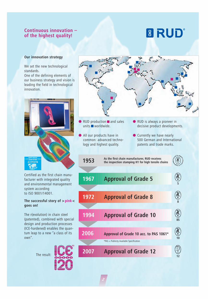
Our innovation strategy
We set the new technological
standards.
One of the defining elements of
our business strategy and vision is
leading the field in technological
innovation.
The successful story of > pink <
goes on!
The r(evolution) in chain steel
(patented), combined with special
design and production processes
(ICE-hardened) enables the quan-
tum leap to a new “a class of its
own”.
� RUD production and sales units worldwide.
� All our products have in common: advanced techno-
logy and highest quality.
� RUD is always a pioneer in decisive product developments.
� Currently we have nearly 500 German and International
patents and trade marks.
�
�
�
�
5
8
8S
10
12
1967 Approval of Grade 5
�
As the first chain manufacturer, RUD receivesthe inspection stamping H1 for high tensile chains
1972 Approval of Grade 8
1994 Approval of Grade 10
2006 Approval of Grade 10 acc. to PAS 1061*
2007 Approval of Grade 12
*PAS = Publicity Available Specification
®
1953
The result:
Certified as the first chain manu-
facturer with integrated quality
and environmental management
system according
to ISO 9001/14001.
�
�
�
�
�
�
�
�
�
� �
�
�
�
� �
�
�
�� �
�
3
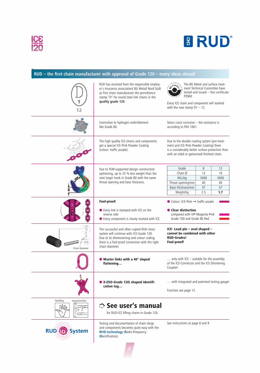
RUD – the first chain manufacturer with approval of Grade 120 – many ideas ahead!
RUD has received from the responsible employ-
er´s insurance association( BG Metall Nord Süd)
as first chain manufacturer the permittance
stamp “D” for round steel link chains in the
quality grade 120. Every ICE chain and component will marked
with the new stamp D1 – 12.
The high quality ICE-chains and components
get a special ICE-Pink-Powder Coating
(colour: traffic purple).
Due to FEM-supported design construction
optimizing, up to 25 % less weight than the
next larger hook in Grade 80 with the same
throat opening and base thickness.
The successful and often copied RUD clevis
system will continue with ICE-Grade 120.
Due to its dimensioning and colour coding,
there is a fool-proof connection with the right
chain diameter.
Testing and documentation of chain slings
and components becomes quite easy with the
RFID-technology (Radio Frequency
IDentification).
See instructions at page 8 and 9
See user’s manualfor RUD-ICE lifting chains in Grade 120.
… only with ICE – suitable for the assembly
of the ICE-Connector and the ICE-Shortening
Coupler!
… with integrated and patented testing gauge!
Function see page 12.
� Master links with a 40° sloped flattening…
� X-(ISO-Grade 120) shaped identifi- cation tag…
� Colour: ICE-Pink � traffic purple
� Clear distinctioncompared with VIP-Magenta-Pink
Grade 100 and Grade 80 Red
Fool-proof:
� Every link is stamped with ICE on the reverse side
� Every component is clearly marked with ICE
Due to the double coating system (pre-treat-
ment and ICE-Pink-Powder Coating) there
is a considerably better surface protection than
with an oiled or galvanized finished chain.
Stress crack corrosion – the resistance is
according to PAS 1061.
Insensitive to hydrogen embrittlement
like Grade 80.
12
Grade 8 12
Chain Ø 13 10
WLL/kg 5000 5000
Throat opening/mm 40 40
Base thickness/mm 37 37
Weight/kg 2.5 1.7
ICE- Load pin – oval shaped – cannot be combined with other RUD-Grades!Fool-proof!
Chain diameter
�Handling Inspection/Test
The BG Metal and surface treat-ment Technical Committee havetested and issued – Test certificatePZNM.
ICE

4
The best in chain technology!
Comparison: single leg chain sling terminating in a sling hook H1-V, EWL = 3000
12
= Innovative
= Chain
= Evolution
The r(evolution) in chain steel (patented) and in the production process (ICE-hardened)
enables the quantum leap to a new “class of its own”.
®
WLL 8 t 8 t
Chain diameter 13 mm 16 mm
IAK-SC-13 AK 1-16 + 3 links + VS-16 + 3 links + V16
ComponentICE-Chain 13 x 39 Chain 16 x 48 GK 8
Length 3.000 mm Length 3.000 mm
ICE-STAR-Hook 13 GSH 16
Weight 20.7 kg = 100 % 26.8 kg = 130 %
Price gross 100 % 130 %
RUD – RUD – Grade 80
DIN EN 818-4
12 8
5
Reduction of weight = extremely light construction
The decisive ICE-advantages – always one diameter thinner than Grade 8!
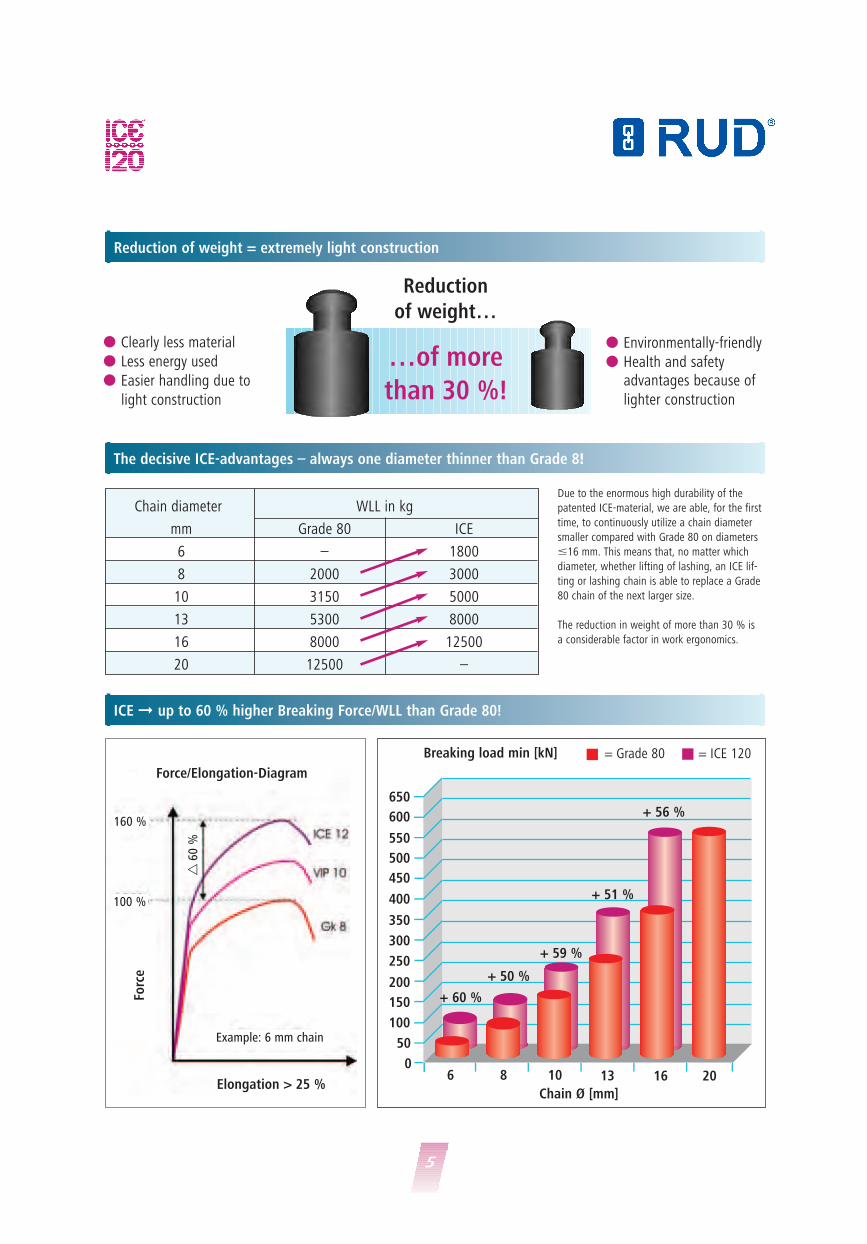
ICE � up to 60 % higher Breaking Force/WLL than Grade 80!
Reduction
of weight…
…of more
than 30 %!
� Environmentally-friendly
� Health and safety advantages because of
lighter construction
� Clearly less material
� Less energy used
� Easier handling due to
light construction
Chain diameter WLL in kg
mm Grade 80 ICE
6 – 1800
8 2000 3000
10 3150 5000
13 5300 8000
16 8000 12500
20 12500 –
Due to the enormous high durability of the
patented ICE-material, we are able, for the first
time, to continuously utilize a chain diameter
smaller compared with Grade 80 on diameters
�16 mm. This means that, no matter which
diameter, whether lifting of lashing, an ICE lif-
ting or lashing chain is able to replace a Grade
80 chain of the next larger size.
The reduction in weight of more than 30 % is
a considerable factor in work ergonomics.
6 8
350
400
450
500
550
600
650
300
250
200
150
100
50
010 13 16 20
+ 59 %
Breaking load min [kN]
Chain Ø [mm]
= Grade 80 = ICE 120
Force/Elongation-Diagram
Forc
e
Elongation > 25 %
+ 50 %
+ 60 %
+ 51 %
+ 56 %160 %
Example: 6 mm chain
100 %
�60
%
6
Quality class 12 – Grade 120 – Breaking strength = 1200 N/mm2
Temperature
Despite ICE having a considerably higher breaking strength =
1200 N/mm2 compared with Quality grade 80 – 800 N/mm2 the elonga-
tion at break remains the same!
The elongation at rupture is guaranteed with � 25 % in natural blackcondition. When pink powder coated, the elongation is � 20 %.
Dynamic test results guaranteeat least 20.000 load cycles withICE in 50 % over load!
In permanent operation, e.g. in connection
with hoist devices and cranes with high dyna-
mic applications - > 20.000 load cycles, the
WLL must be determined according to EN 818-
7 Mechanism group 1 Bm (M3), a mean stress
of 160 N/mm2 that means, for example, a lar-
ger chain diameter.��
Hot or cold – ICE is the best!
Ideal for Polar and
Arctic use;
Extremely tempera-
ture resistant-60°C up to +300°CResistance to brittle
fracture < -70°C.
��
+300°C
-60°C
Overheating indicator EP 677681 (European Patent)
The special ICE-Pink-PowderCoating shows the effects oftemperature in which thechain can be safely used. Itis prohibited to use the ICE-Pink chain in temperaturesof more than 300°C. This isclearly displayed by ICE-Pinkcolour turning brown-black.
The ICE-Chains must betaken out of service or sentthem back to the manufactu-rer for maintenance!225° C 250° C 275° C 300° C
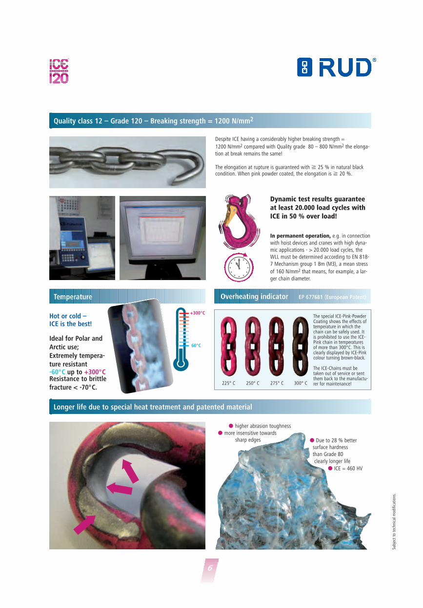
Longer life due to special heat treatment and patented material
�
�
�
� higher abrasion toughness
� more insensitive towards sharp edges � Due to 28 % better
surface hardness
than Grade 80
clearly longer life
� ICE = 460 HV
Subj
ect
to t
echn
ical
mod
ifica
tion
s.
7
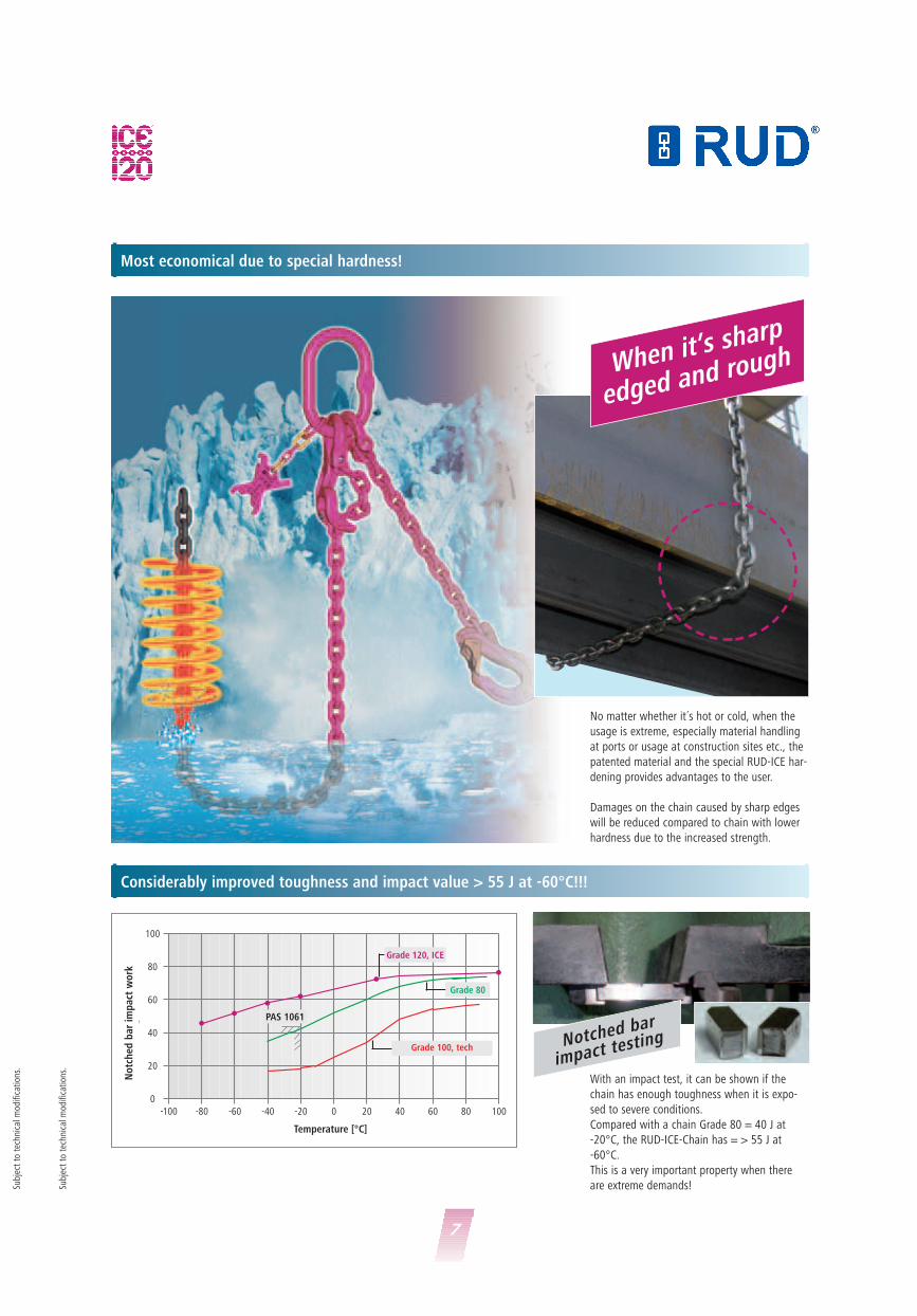
Most economical due to special hardness!
Considerably improved toughness and impact value > 55 J at -60°C!!!
When it’s sharp
edged and rough
No matter whether it´s hot or cold, when the
usage is extreme, especially material handling
at ports or usage at construction sites etc., the
patented material and the special RUD-ICE har-
dening provides advantages to the user.
Damages on the chain caused by sharp edges
will be reduced compared to chain with lower
hardness due to the increased strength.
With an impact test, it can be shown if the
chain has enough toughness when it is expo-
sed to severe conditions.
Compared with a chain Grade 80 = 40 J at
-20°C, the RUD-ICE-Chain has = > 55 J at
-60°C.
This is a very important property when there
are extreme demands!
-100
100
80
60
40
20
0-80 -60 -40 -20 0 20 40 60 80 100
Temperatur [°C]
Ker
bsch
laga
rbei
t K
v[J
]
�
�
��
��
Grad 12, ICE
PAS 1061
Grad 10, Low tech
Grad 8
Notched bar
impact testing
Subj
ect
to t
echn
ical
mod
ifica
tion
s.
Subj
ect
to t
echn
ical
mod
ifica
tion
s.
No
tch
ed b
ar
imp
act
wo
rk
Temperature [°C]
Grade 120, ICE
Grade 100, tech
Grade 80

8
Inspection and documentation made easy!
RUD-ID-EASY-CHECK®
Required, regularly inspections of lifting means are currently still timeconsuming and often sensible in regard of fault-prone.
But due to the RFID-technology(Radio-Frequenz-IDentifikation)these time consuming methods andhuge amount of paper work beco-me history.
Chain slings/components can nowcontactless, faultless and fast iden-tified and with the clearIdentification number they can beregistered and conducted.
The modern and digital times of documentation and administrationof work means reaches herby anew peak point.
The components can be marked by the RUD-ID-Point® (RFID chip)and with the clear identificationnumber distinguished.
The robust RUD-ID-EASY-CHECK®
readers capture the Identificationnumber of the RUD-ID-Point® andtransfer it to the RUD-ID-NET®
application (software), resp. optio-nally to your PC application likeWordPad, MS Word, MS Excel, SAP etc.
The extendable RUD-ID-NET®
application (software) will supportyour product administration anddocumentation
RUD-ID-POINT® RUD-ID-NET®
Subj
ect
to t
echn
ical
mod
ifica
tion
s.

9
RUD-ID-EASY-CHECK®
The exclusive and unbeatable RUD-ID-Point® persuades at difficult applications and ambient conditi-ons. Applicable between -80°C and+270°C. Extreme high resistanceagainst beats, water and pollution. No impairment of serviceability andcapability of components by the embedded RFID-Chip.
RUD-ID-Point® 8 mm(13.56 MHz HF):Press-fit transponder (in metal). Noglue necessary. Size: 8 mm x 3.25mm.
The RUD-ID-EASY-CHECK® readersare compatible with the RUD-ID-Points® as well as with commonhigh frequency transponders/chips(ISO 15693). The transfer of theidentification number is carried outeither by USB or Bluetooth and can be linked up with the RUD-ID-NET® application (software), almostall Office applications (WordPad,MS Word, MS Excel, Open Office)and also with SAP or other pro-grams.
The RUD-ID-NET® application(software) makes many thingseasier. This application supportsyou amongst others, like testinspection.
� Uncomplicated digital mainten-ance, analysis, administration of product datas, test reports, as well as documents (efficientcarry out of test, automatic testreminder in addition to the by law required test, automatic testreports).
� Digital connection to current product information and docu-ments (f.e. test reports) withaccess to the RUD web portal.
� Extendable software for differentwork equipment which has to be inspected regularly (f.e. workplatforms, roller shutter).
The usage of RFID-Chips embed-ded into a hole of a lifting and con-veying? Safety component is protec-ted by a patent.
RUD-ID-TAG® (13.56 MHz HF):Metal reinforced tag for chains,connecting links, wire ropes, alter-natively also for bolting. Size: 50 mm x 32 mm x 6 mm
RUD-ID-EASY-CHECK®
(13.56 MHz):USB-reader for reading out oftheRUD-ID-Point® identificationnumber.
RUD-ID-DISPLAY-CHECK®
(13.56 MHz):Bluetooth reader, reads out the uni-que RUD-ID-Point® identificationnumber, shows it on the integratedLCD display and transfoms it up to a distance of 15 mm to the PC(laptop).
RUD-ID-POINT®
RUD-ID-NET®
8 mm
50 m
m
Reference no.:7998881
Reference no.:7901288
Reference no.: 7901000
Reference no.: 7901524 (Bluetooth)
Subj
ect
to t
echn
ical
mod
ifica
tion
s.
Subj
ect
to t
echn
ical
mod
ifica
tion
s.

10
The Modular-Mecano System ICE Grade 120
Assembly
We do not assume liability for damage which in
respect of disregard of these norms and safety
information.
Handling:Chains and components of ICE-Grade 120 must
not be combined with chains and components
of other manufacturers or quality classes.
Attention:Incorrect handling and use of these lifting
chains can lead to material and/ or personal
damage!
Important safety information must beobserved:DIN-EN 818, DIN-EN 1677, BGR 500 chapter
2.8, EU-Directives 2006/42/EG and manufactu-
rer’s manual.
ICE-Master links
ICE-Connectingitems
Shortening elements
End fittings
Additional components
ICE-Shortening
Coupler
ICE-Shortening
hook
ICE-Curt
with spindle- or clevis
connection
*Clevis-shackle
ICE-Multi
Shortening Claw
ICE-Connector ICE-Connecting link
ICE-KZA ICE-IAK-1
ICE-C
ICE-IA
New!
Subj
ect
to t
echn
ical
mod
ifica
tion
s.
ICE-H-Chain-Connector
New!
New!
ICE-Star-Hook
(Star-Haken)
ICE-Dumper truck
suspenion-ring
IB IA
New!
ICE-Balancer
New!
ICE-oval-G-pin
Chain diameter
Chain Type Ref. No.
6 IOG-6/Retaining pin 6 7998740
8 IOG-8/Retaining pin 8 7995739
10 IOG-10/Retaining pin 10 7995740
13 IOG-13/Retaining pin 13 7995741
16 IOG-16/Retaining pin 16 7999102*
ICE-oval G-pin and retaining pin
Only available in packs of 10 (*packs of 4).
Only use original RUD-ICE parts. Design of load pin results in “Fool-proof”
system compared with other RUD Grades.
ICE
ICE-Automatic-
Clevis hook
ICE-Dump truck-
Automatic-Clevis hook

11
ICE Grade 120 WLL chart [t]
RUD ICE-120-Chains and components conform fully to the requirements of EN 818 and 1677 for dynamic applications of 20,000 load cycles, with
50 % over load.
The German employer’s liability assurance association requires: When there are dynamic applications with high load cycles (permanent operation) the
mean stress corresponding to the Mechanism group 1 Bm (M3 according to DIN EN 818-7) must be reduced, for example, by using a larger chain
diameter.
When requiring lower or higher WLL, up to 126 tons, please choose the corresponding chain from our VIP-Program (s. pages 36-37).
In connection with ICE-balancer up to 22.4 t (s. page 27/W).
1-leg 2-leg 3- and 4-leg endless
Nominal size of endless chainsling chain in mm in choke hitch
Inclination-� � 0° 0-45° > 45-60° 0-45° > 45-60° -
Load factor 1 1.4 1 2.1 1.5 1.6
Ø 6 1.8 2.5 1.8 3.75 2.7 2.88
Ø 8 3.0 4.25 3.0 6.3 4.5 4.8
Ø 10 5.0 7.1 5.0 10.6 7.5 8.0
Ø 13 8.0 11.2 8.0 17.0 11.8 12.8
Ø 16 12.5 17.0 12.5 26.5 19.0 20.0
In case of unsymmetrical loading, the WLLmust be reduced by 50 %.
In case of unsymmetrical loading, the WLLmust be reduced by 50 %.
Endless chain Choke hitch
Nominal size ofsling chain in mm
single double single double
Inclination-� � 0-45° > 45-60° 0-45° > 45-60° 0° 0-45° > 45-60°
Load factor 1.1 0.8 1.7 1.2 0.8 1.1 0.8
Ø 6 2.0 1.44 3.1 2.1 1.44 2.0 1.44
Ø 8 3.3 2.4 5.1 3.6 2.4 3.3 2.4
Ø 10 5.5 4.0 8.5 6.0 4.0 5.5 4.0
Ø 13 8.8 6.4 13.6 9.6 6.4 8.8 6.4
Ø 16 14.0 10.0 21.2 15.0 10.0 14.0 10.0
When using sling chains at temperatures beyond 200°C the permissible WLL has to be reduced.Working load in % at chain temperature of:
-60 up to +200° C
100 %über 200 up to 250° C
90 %
über 250 up to 300° C
60 %
Temperatur
°C
Subj
ect
to t
echn
ical
mod
ifica
tion
s.
Subj
ect
to t
echn
ical
mod
ifica
tion
s.

12
ICE-Round steel link chain in special quality 120
ICE identification tag with an integrated chain testing gauge – ICE-KZA
Size d 6 8 10 13 16in mm Ø
Pitch P 18 24 30 39 48mm
Inside, width 7.8 10.4 13 17 21W1 bi min. mm
WLL 1.8 3.0 5.0 8.0 12.5in t
Proof load 44.1 73.5 123 196 314MPF in kN
Breaking load 71 118 196 314 503BF min. kN
Weight 0.98 1.66 2.62 4.25 6.72kg/m
Surface pink powder coated ICE-Pink
Order no. 7998048 7996116 7996117 7996118 7998735
Surface phosphated in natural black
Order no. 7994424 7996122 7996123 7996124 7994428
Minimal ultimate elongation: natural black � 25 % ICE-PINK � 20 %Stamped: ICE identification on every chain link, manufacturing number and the BG approval stamp < 0.5 m
Testing
wear of nominal diameterTesting
of plastic elongation caused
by overload
Testing
for pitch elongation caused
by wear of nominal diameter
Engraving the next
testing date
Assembly – number of legs
(multiple-leg)Wear test of the nominal diameter
with indication of
the minimal
Ø (-10 % dm)
ICE WLL with indicati-on of inclination angle
Testing of plastic elongation
caused by overloading
Chain pitch gauge testing
for pitch elongation caused
by wear of nominal diameter
ICE-WLL
(single leg)
Identification number
Chain diameter Ø
Front Reverse
The patented idea!
Subj
ect
to t
echn
ical
mod
ifica
tion
s.
1213
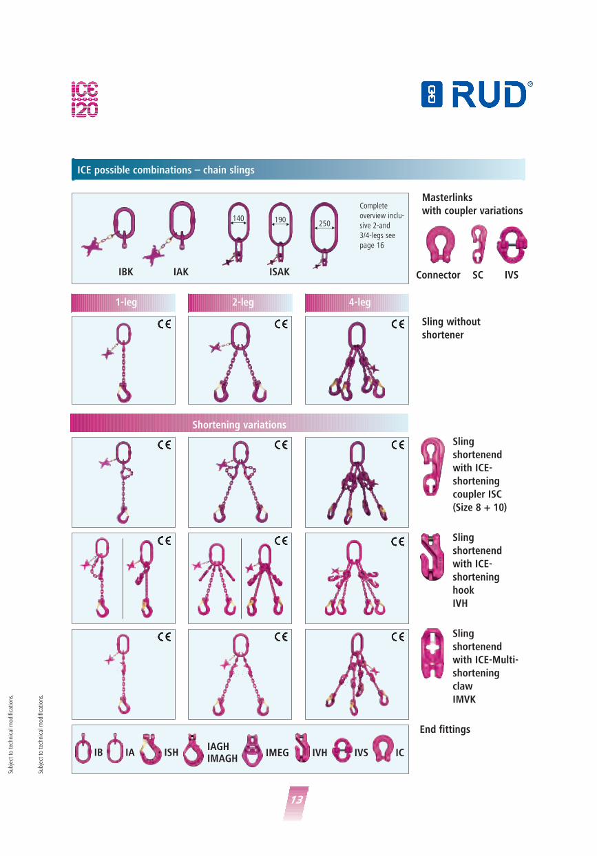
ICE possible combinations – chain slings
1-leg
Shortening variations
2-leg 4-leg
Masterlinks
with coupler variations
Sling without
shortener
Sling
shortenend
with ICE-
shortening
coupler ISC
(Size 8 + 10)
Sling
shortenend
with ICE-
shortening
hook
IVH
Complete
overview inclu-
sive 2-and
3/4-legs see
page 16
IBK IAK ISAK
��140
��190
��250
Sling
shortenend
with ICE-Multi-
shortening
claw
IMVK
End fittings
Connector SC IVS
Subj
ect
to t
echn
ical
mod
ifica
tion
s.
Subj
ect
to t
echn
ical
mod
ifica
tion
s.
IVHIMEG IVS ICIAGHIMAGH
ISHIAIB

Single Double endless
Masterlink variations
endless chain
unshortened
IH
Endless chain
shortened with
ICE-shortenig coupler
ISC
Endless chain
shortened with
ICE-shortenig coupler
IVH
Complete
overview inclu-
sive 2-and
3/4-legs see
page 16
IBK IAK ISAK
��140
��190
��250
Endless chain
shortened with
ICE-Multi-shortenig
coupler
IMVK
14
ICE combination variations – endless chains
Subj
ect
to t
echn
ical
mod
ifica
tion
s.
Subj
ect
to t
echn
ical
mod
ifica
tion
s.
�
�
L
New!

15
ICE-master links and ICE-end links – Variety example of ICE connector *end fitting
Subj
ect
to t
echn
ical
mod
ifica
tion
s.
Grade Endless Single (E)/ Without shortening (U)/ Shortening/ Chain Requested reachchain Double (D) shortened (V) Component diameter [mm] unshortened
ICE KR single = E shortened = V ISC 8 2000
ICE-KREV(ISC)-8-2000
Example:
Example:
�
�
L
Quality No. of Masterlink Shortening/ Shortening/ End fitting Chain Requested reachgrade strands strands component diameter [mm]
unshortened
ICE G1 (IBK) – – ISH 13 2000
ICE-G1(IBK)-ISH/13x2000
ICE-execution resp. calculation examples – complete sling resp. endless chain
1-leg 2-leg 3/4-leg
Alternativly the ICE
Connector can either be
replaced with the ICE-
Shortening coupler (1)
or with the
ICE-connector (2).
IBK/IB*
IAK/IA*
ISAK
140 140 140190 190 190250 250 250
IBK IB*
IAK IA* IAK IA* IAK IA*
IBK IB* IB*
*End fittings
(1) (2)
ICE Identification tag
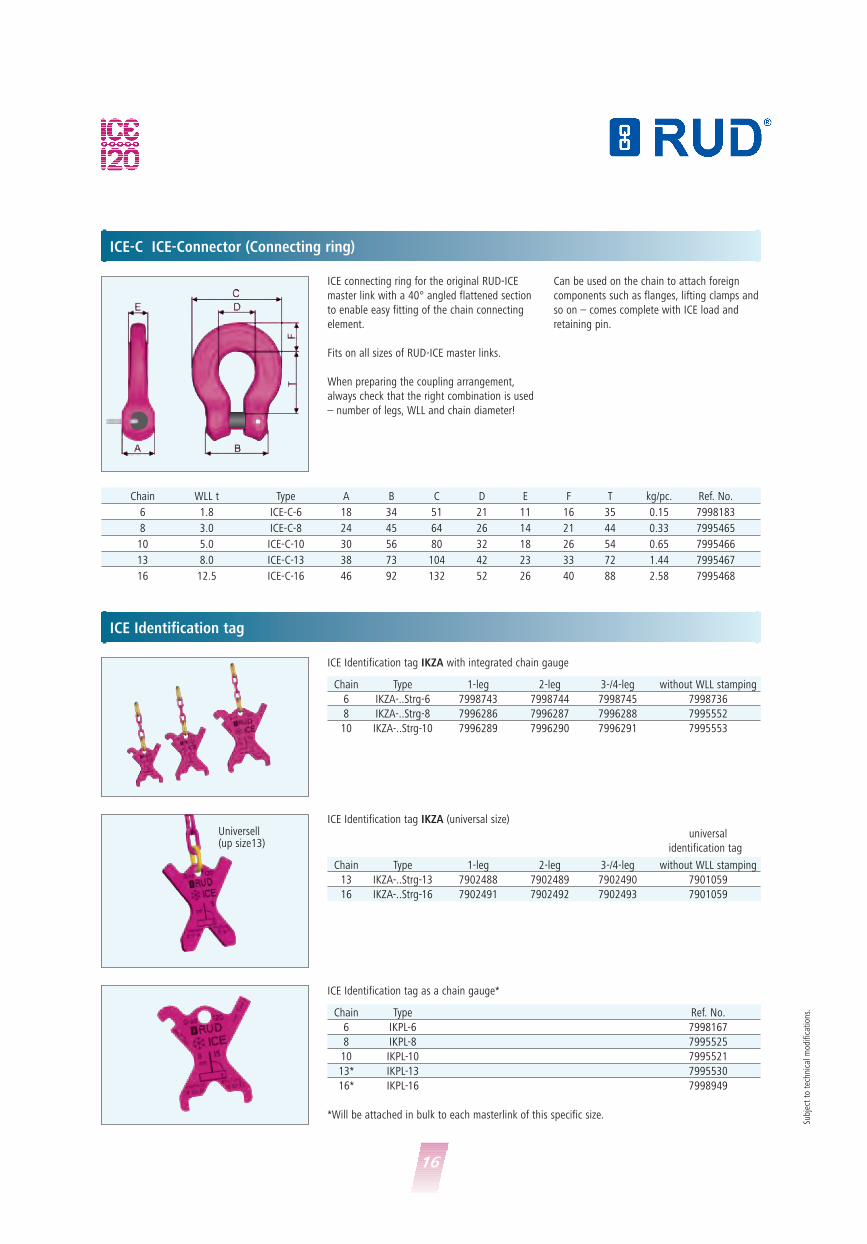
ICE-C ICE-Connector (Connecting ring)
Chain WLL t Type A B C D E F T kg/pc. Ref. No.
6 1.8 ICE-C-6 18 34 51 21 11 16 35 0.15 7998183
8 3.0 ICE-C-8 24 45 64 26 14 21 44 0.33 7995465
10 5.0 ICE-C-10 30 56 80 32 18 26 54 0.65 7995466
13 8.0 ICE-C-13 38 73 104 42 23 33 72 1.44 7995467
16 12.5 ICE-C-16 46 92 132 52 26 40 88 2.58 7995468
ICE connecting ring for the original RUD-ICE
master link with a 40° angled flattened section
to enable easy fitting of the chain connecting
element.
Fits on all sizes of RUD-ICE master links.
When preparing the coupling arrangement,
always check that the right combination is used
– number of legs, WLL and chain diameter!
Can be used on the chain to attach foreign
components such as flanges, lifting clamps and
so on – comes complete with ICE load and
retaining pin.
16
Subj
ect
to t
echn
ical
mod
ifica
tion
s.
Chain Type 1-leg 2-leg 3-/4-leg without WLL stamping
6 IKZA-..Strg-6 7998743 7998744 7998745 7998736
8 IKZA-..Strg-8 7996286 7996287 7996288 7995552
10 IKZA-..Strg-10 7996289 7996290 7996291 7995553
ICE Identification tag IKZA with integrated chain gauge
Chain Type Ref. No.
6 IKPL-6 7998167
8 IKPL-8 7995525
10 IKPL-10 7995521
13* IKPL-13 7995530
16* IKPL-16 7998949
ICE Identification tag as a chain gauge*
Chain Type 1-leg 2-leg 3-/4-leg without WLL stamping
13 IKZA-..Strg-13 7902488 7902489 7902490 7901059
16 IKZA-..Strg-16 7902491 7902492 7902493 7901059
ICE Identification tag IKZA (universal size)
universal
identification tag
*Will be attached in bulk to each masterlink of this specific size.
Universell(up size13)
17
Subj
ect
to t
echn
ical
mod
ifica
tion
s.
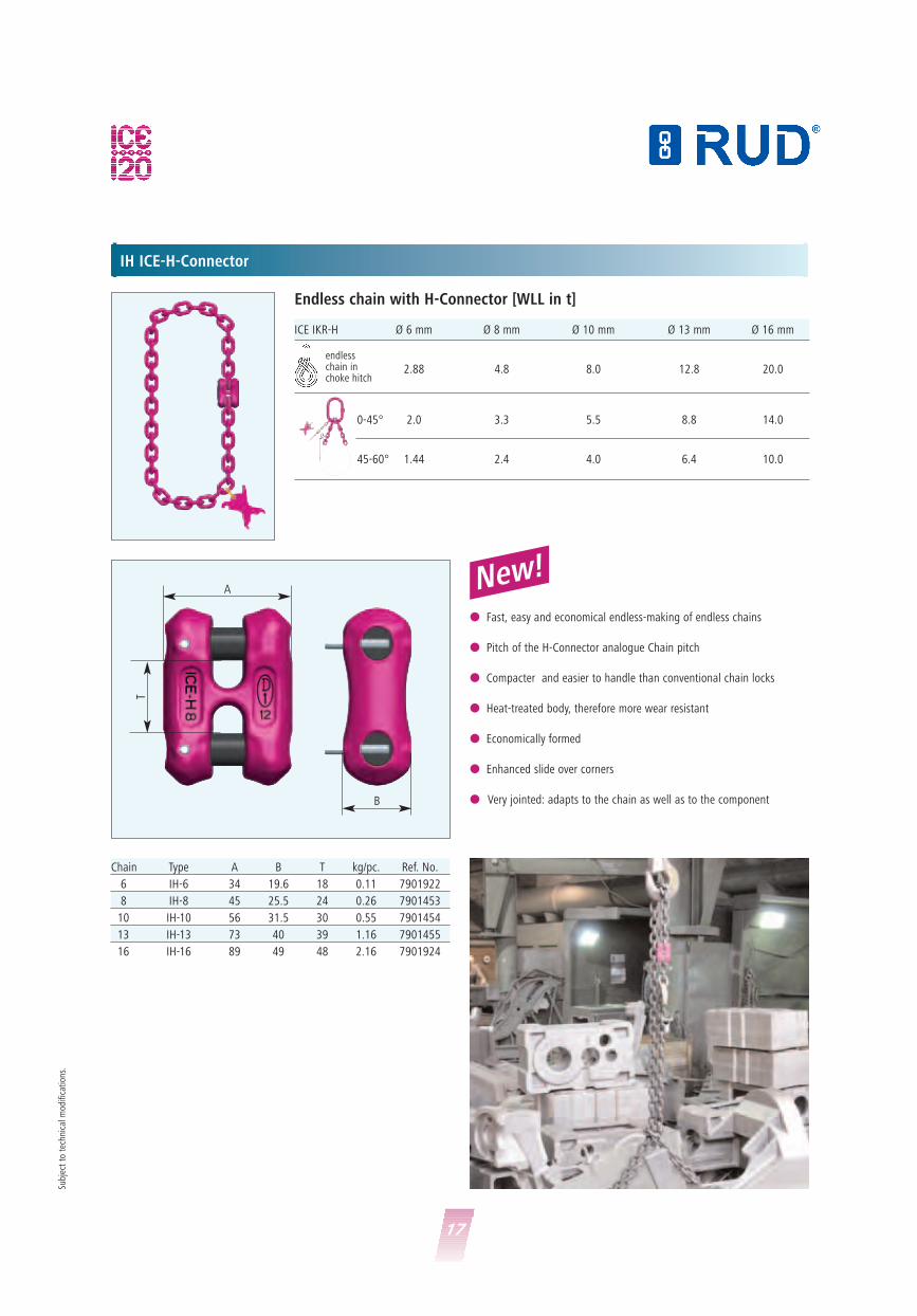
IH ICE-H-Connector
ICE IKR-H Ø 6 mm Ø 8 mm Ø 10 mm Ø 13 mm Ø 16 mm
2.88 4.8 8.0 12.8 20.0
2.0 3.3 5.5 8.8 14.0
1.44 2.4 4.0 6.4 10.0
endlesschain inchoke hitch
0-45°
45-60°
Endless chain with H-Connector [WLL in t]
New!A
B
T
� Fast, easy and economical endless-making of endless chains
� Pitch of the H-Connector analogue Chain pitch
� Compacter and easier to handle than conventional chain locks
� Heat-treated body, therefore more wear resistant
� Economically formed
� Enhanced slide over corners
� Very jointed: adapts to the chain as well as to the component
Chain Type A B T kg/pc. Ref. No.
6 IH-6 34 19.6 18 0.11 7901922
8 IH-8 45 25.5 24 0.26 7901453
10 IH-10 56 31.5 30 0.55 7901454
13 IH-13 73 40 39 1.16 7901455
16 IH-16 89 49 48 2.16 7901924

18
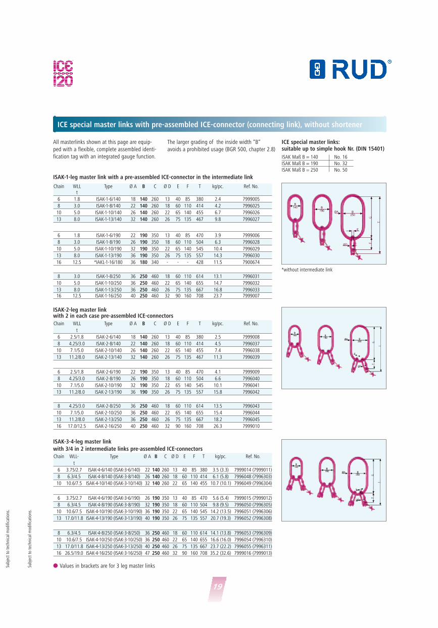
ICE masterlinks with pre-assembled ICE connector (connecting link), without shortening.
All masterlinks shown at this page are equip-
ped with a flexible, complete assembled identi-
fication tag with an integrated gauge function.
IAK master links
Dimensions comply to master link type A acc.
to DIN 5688, but one nominal size bigger.
IBK-master links
The inside width of the IBK master links is ade-
quate to fit high tensile load hooks of hoists.
IAK-1-and IBK-master links or end links with pre-assembled ICE-Connector
IAK-3-4 master link with 3 or 4 in 2 intermediate links pre-assembled ICE-connectors
IAK-master links:suitable up to crane hook size no. (DIN 15401)
Chain WLL Type Ø A B C Ø D E F T kg/pc. Ref. No.
t
6 3.75/2.7 IAK-4-6 (IAK-3-6) 18 90 160 13 40 85 280 3.1 (2.9) 7998216 (7999001)
8 6.3/4.5 IAK-4-8 (IAK-3-8) 26 100 180 18 60 110 334 5.4 (5.0) 7995568 (7996321)
10 10.6/7.5 IAK-4-10 (IAK-3-10) 32 110 200 22 65 140 394 9.7 (9.0) 7995569 (7996322)
13 17.0/11.8 IAK-4-13 (IAK-3-13) 36 140 260 26 75 135 467 16.6 (15.1) 7995570 (7996323)
16 26.5/19.0 IAK-4-16 (IAK-3-16) 46 190 350 32 90 160 598 31.3 (28.7) 7999003 (7999002)
Chain WLL Type Ø A B C T kg/pc. Ref. No.
t
6 1.8 IAK-1-6 (IA-1-6) 13 60 110 145 0.6 (0.5) 7998989 (7998991)
8 3.0 IAK-1-8 (IA-1-8) 18 75 135 179 1.4 (1.2) 7995561 (7996133)
10 5.0 IAK-1-10 (IA-1-10) 22 90 160 214 2.5 (2.2) 7995562 (7996134)
13 8.0 IAK-1-13 (IA-1-13) 26 100 180 252 4.2 (3.9) 7995563 (7996135)
16 12.5 IAK-1-16 (IA-1-16) 32 140 260 348 8.0 (7.5) 7998990 (7998992)
6 1.8 IBK-1-6 (IB-1-6) 13 40 85 120 0.6 (0.5) 7998987 (7998995)
8 3.0 IBK-1-8 (IB-1-8) 18 60 110 154 1.3 (1.1) 7995715 (7996139)
10 5.0 IBK-1-10 (IB-1-10) 22 65 140 194 2.2 (2.0) 7995716 (7996140)
13 8.0 IBK-1-13 (IB-1-13) 26 75 135 207 3.7 (3.3) 7995717 (7996141)
16 12.5 IBK-1-16 (IB-1-16) 32 90 160 248 6.5 (6.0) 7998988 (7998996)
IAK-2- and IBK-2-master link with two pre-assembled ICE-connectors
Chain WLL Type Ø A B C T kg/pc. Ref. No.
t
6 2.5/1.8 IAK-2-6 16 75 135 170 1.1 7998997
8 4.25/3.0 IAK-2-8 22 90 160 204 2.4 7995565
10 7.1/5.0 IAK-2-10 26 100 180 234 4.0 7995566
13 11.2/8.0 IAK-2-13 32 110 200 272 7.5 7995567
16 17.0/12.5 IAK-2-16 36 180 340 428 14.1 7998998
6 2.5/1.8 IBK-2-6 13 40 85 120 0.7 7998999
8 4.25/3.0 IBK-2-8 18 60 110 154 1.6 7995718
10 7.1/5.0 IBK-2-10 22 65 140 194 2.1 7995719
13 11.2/8.0 IBK-2-13 26 75 135 207 5.1 7995720
16 17.0/12.5 IBK-2-16 32 90 160 248 9.0 7999000
� ICE connecting bolts and securing sleeve pin pre-assembled� Also available as end link (IA-1), without identification tag
� Values in brackets are for 3 leg master links
Size 6 8 10 13 16
IAK 1 No. 2.5 No. 5 No. 6 No. 8 No. 16IAK 2 No. 5 No. 6 No. 8 No. 10 No. 25IAK 3/4 No. 6 No. 8 No. 10 No. 16 No. 32 Su
bjec
t to
tec
hnic
al m
odifi
cati
ons.
19
ICE special master links with pre-assembled ICE-connector (connecting link), without shortener
All masterlinks shown at this page are equip-
ped with a flexible, complete assembled identi-
fication tag with an integrated gauge function.
The larger grading of the inside width “B“
avoids a prohibited usage (BGR 500, chapter 2.8)
ISAK-1-leg master link with a pre-assembled ICE-connector in the intermediate link
ISAK-2-leg master linkwith 2 in each case pre-assembled ICE-connectors
ISAK-3-4-leg master link
with 3/4 in 2 intermediate links pre-assembled ICE-connectors
Chain WLL Type Ø A B C Ø D E F T kg/pc. Ref. No.t
6 1.8 ISAK-1-6/140 18 140 260 13 40 85 380 2.4 7999005
8 3.0 ISAK-1-8/140 22 140 260 18 60 110 414 4.2 7996025
10 5.0 ISAK-1-10/140 26 140 260 22 65 140 455 6.7 7996026
13 8.0 ISAK-1-13/140 32 140 260 26 75 135 467 9.8 7996027
6 1.8 ISAK-1-6/190 22 190 350 13 40 85 470 3.9 7999006
8 3.0 ISAK-1-8/190 26 190 350 18 60 110 504 6.3 7996028
10 5.0 ISAK-1-10/190 32 190 350 22 65 140 545 10.4 7996029
13 8.0 ISAK-1-13/190 36 190 350 26 75 135 557 14.3 7996030
16 12.5 *IAKL-1-16/180 36 180 340 - - - 428 11.5 7900674
8 3.0 ISAK-1-8/250 36 250 460 18 60 110 614 13.1 7996031
10 5.0 ISAK-1-10/250 36 250 460 22 65 140 655 14.7 7996032
13 8.0 ISAK-1-13/250 36 250 460 26 75 135 667 16.8 799603316 12.5 ISAK-1-16/250 40 250 460 32 90 160 708 23.7 7999007
Chain WLL- Type Ø A B C Ø D E F T kg/pc. Ref. No.
t
6 3.75/2.7 ISAK-4-6/140 (ISAK-3-6/140) 22 140 260 13 40 85 380 3.5 (3.3) 7999014 (7999011)
8 6.3/4.5 ISAK-4-8/140 (ISAK-3-8/140) 26 140 260 18 60 110 414 6.1 (5.8) 7996048 (7996303)
10 10.6/7.5 ISAK-4-10/140 (ISAK-3-10/140) 32 140 260 22 65 140 455 10.7 (10.1) 7996049 (7996304)
6 3.75/2.7 ISAK-4-6/190 (ISAK-3-6/190) 26 190 350 13 40 85 470 5.6 (5.4) 7999015 (7999012)
8 6.3/4.5 ISAK-4-8/190 (ISAK-3-8/190) 32 190 350 18 60 110 504 9.8 (9.5) 7996050 (7996305)
10 10.6/7.5 ISAK-4-10/190 (ISAK-3-10/190) 36 190 350 22 65 140 545 14.2 (13.5) 7996051 (7996306)
13 17.0/11.8 ISAK-4-13/190 (ISAK-3-13/190) 40 190 350 26 75 135 557 20.7 (19.3) 7996052 (7996308)
8 6.3/4.5 ISAK-4-8/250 (ISAK-3-8/250) 36 250 460 18 60 110 614 14.1 (13.8) 7996053 (7996309)
10 10.6/7.5 ISAK-4-10/250 (ISAK-3-10/250) 36 250 460 22 65 140 655 16.6 (16.0) 7996054 (7996310)
13 17.0/11.8 ISAK-4-13/250 (ISAK-3-13/250) 40 250 460 26 75 135 667 23.7 (22.2) 7996055 (7996311)
16 26.5/19.0 ISAK-4-16/250 (ISAK-3-16/250) 47 250 460 32 90 160 708 35.2 (32.6) 7999016 (7999013)
Chain WLL Type Ø A B C Ø D E F T kg/pc. Ref. No.
t
6 2.5/1.8 ISAK-2-6/140 18 140 260 13 40 85 380 2.5 7999008
8 4.25/3.0 ISAK-2-8/140 22 140 260 18 60 110 414 4.5 7996037
10 7.1/5.0 ISAK-2-10/140 26 140 260 22 65 140 455 7.4 7996038
13 11.2/8.0 ISAK-2-13/140 32 140 260 26 75 135 467 11.3 7996039
6 2.5/1.8 ISAK-2-6/190 22 190 350 13 40 85 470 4.1 7999009
8 4.25/3.0 ISAK-2-8/190 26 190 350 18 60 110 504 6.6 7996040
10 7.1/5.0 ISAK-2-10/190 32 190 350 22 65 140 545 10.1 7996041
13 11.2/8.0 ISAK-2-13/190 36 190 350 26 75 135 557 15.8 7996042
8 4.25/3.0 ISAK-2-8/250 36 250 460 18 60 110 614 13.5 7996043
10 7.1/5.0 ISAK-2-10/250 36 250 460 22 65 140 655 15.4 7996044
13 11.2/8.0 ISAK-2-13/250 36 250 460 26 75 135 667 18.2 7996045
16 17.0/12.5 ISAK-2-16/250 40 250 460 32 90 160 708 26.3 7999010
*without intermediate link
ICE special master links:suitable up to simple hook Nr. (DIN 15401)
ISAK Maß B = 140 No. 16
ISAK Maß B = 190 No. 32
ISAK Maß B = 250 No. 50
� Values in brackets are for 3 leg master linksSubj
ect
to t
echn
ical
mod
ifica
tion
s.
Subj
ect
to t
echn
ical
mod
ifica
tion
s.
20
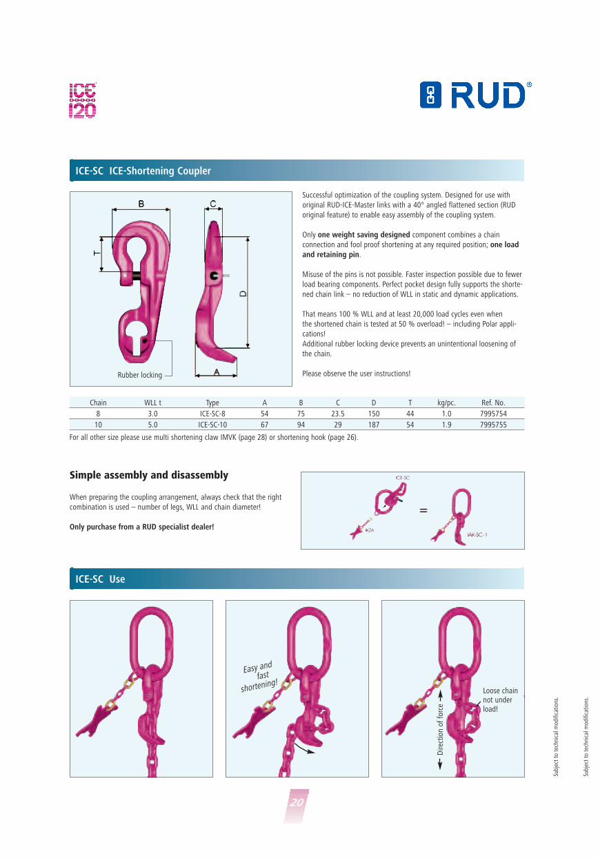
ICE-SC ICE-Shortening Coupler
ICE-SC Use
Chain WLL t Type A B C D T kg/pc. Ref. No.
8 3.0 ICE-SC-8 54 75 23.5 150 44 1.0 7995754
10 5.0 ICE-SC-10 67 94 29 187 54 1.9 7995755
Easy and
fast
shortening!
Successful optimization of the coupling system. Designed for use with
original RUD-ICE-Master links with a 40° angled flattened section (RUD
original feature) to enable easy assembly of the coupling system.
Only one weight saving designed component combines a chain
connection and fool proof shortening at any required position; one load
and retaining pin.
Misuse of the pins is not possible. Faster inspection possible due to fewer
load bearing components. Perfect pocket design fully supports the shorte-
ned chain link – no reduction of WLL in static and dynamic applications.
That means 100 % WLL and at least 20,000 load cycles even when
the shortened chain is tested at 50 % overload! – including Polar appli-
cations!
Additional rubber locking device prevents an unintentional loosening of
the chain.
Please observe the user instructions!
Simple assembly and disassembly
When preparing the coupling arrangement, always check that the right
combination is used – number of legs, WLL and chain diameter!
Only purchase from a RUD specialist dealer!
Rubber locking
Loose chainnot underload!
Dire
ctio
n of
for
ce
Subj
ect
to t
echn
ical
mod
ifica
tion
s.
Subj
ect
to t
echn
ical
mod
ifica
tion
s.
For all other size please use multi shortening claw IMVK (page 28) or shortening hook (page 26).
21
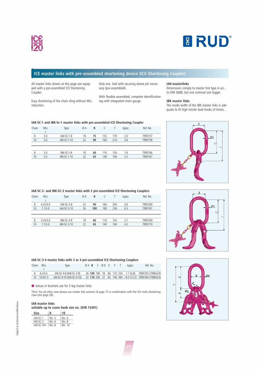
ICE master links with pre-assembled shortening device (ICE-Shortening Coupler)
All master links shown at this page are equip-
ped with a pre-assembled ICE-Shortening
Coupler.
Easy shortening of the chain sling without WLL
reduction.
IAK-masterlinks
Dimensions comply to master link type A acc.
to DIN 5688, but one nominal size bigger.
IBK master links
The inside width of the IBK master links is ade-
quate to fit high tensile load hooks of hoists..
Only one bolt with securing sleeve pin neces-
sary (pre-assembled).
With flexible assembled, complete identification
tag with integrated chain gauge.
Chain WLL Type Ø A B C Ø D E F T kg/pc. Ref. No.
t
8 6.3/4.5 IAK-SC-4-8 (IAK-SC-3-8) 26 100 180 18 60 110 334 7.7 (6.8) 7995763 (7996324)
10 10.6/7.5 IAK-SC-4-10 (IAK-SC-3-10) 32 110 200 22 65 140 394 14.3 (12.5) 7995764 (7996325)
Chain WLL Type Ø A B C T kg/pc. Ref. No.
t
8 3.0 IAK-SC-1-8 18 75 135 179 2.0 7995757
10 5.0 IAK-SC-1-10 22 90 160 214 3.6 7995758
8 3.0 IBK-SC-1-8 18 60 110 154 1.8 7995766
10 5.0 IBK-SC-1-10 22 65 140 194 3.3 7995767
IAK-SC-1 and IBK-Sc-1 master links with pre-assembled ICE-Shortening Coupler
Chain WLL Type Ø A B C T kg/pc. Ref. No.
t
8 4.25/3.0 IAK-SC-2-8 22 90 160 204 3.6 7995760
10 7.1/5.0 IAK-SC-2-10 26 100 180 234 6.3 7995761
8 4.25/3.0 IBK-SC-2-8 18 60 110 154 2.7 7995769
10 7.1/5.0 IBK-SC-2-10 22 65 140 194 4.5 7995770
IAK-SC-2- and IBK-SC-2 master links with 2 pre-assembled ICE-Shortening Couplers
IAK-SC-3-4 master links with 3 or 4 pre-assembled ICE-Shortening Couplers
*Hint: For all other sizes please use master link variants of page 15 in combination with the ICE multi shorteningclaw (see page 28).
IAK-master linkssuitable up to crane hook size no. (DIN 15401)
Size 8 10
IAK-SC-1 No. 5 No. 6IAK-SC-2 No. 6 No. 8IAK-SC-3/4 No. 8 No. 10
� Values in brackets are for 3 leg master links
Subj
ect
to t
echn
ical
mod
ifica
tion
s.

22
ICE Special-master links with pre-assembled shortener (ICE-Shortening Coupler)
ISAK-1-Master link with a preassembled ICE-
Shortening Coupler on the intermediate link.
Easy shortening of the sling chain, no reduction
of the WLL.
Additional rubber locking device prevents an
unintentional loosening of the chain.
Only one load and retaining pin necessary
(preassembled).
The larger grading of the inside width “B“
avoids a prohibited usage (BGR 500, chapter
2.8) and reduces wear at the crane hook.
ISAK-SC-1-leg master links
With ICE-Shortening Coupler pre-assembled in the intermediate link
Chain WLL Type Ø A B C Ø D E F T kg/pc. Ref. No.
8 3.0 ISAK-SC-1-8/140 22 140 260 18 60 110 414 4.7 799606310 5.0 ISAK-SC-1-10/140 26 140 260 22 65 140 455 7.8 7996064
8 3.0 ISAK-SC-1-8/190 26 190 350 18 60 110 504 6.9 799606610 5.0 ISAK-SC-1-10/190 32 190 350 22 65 140 545 11.5 7996067
8 3.0 ISAK-SC-1-8/250 36 250 460 18 60 110 614 13.7 799606910 5.0 ISAK-SC-1-10/250 36 250 460 22 65 140 655 15.8 7996070
ISAK-SC-2-leg master linkswith 2 in each case pre-assembled ICE-connectors
Chain WLL Type Ø A B C Ø D E F T kg/pc. Ref. No.
8 4.25/3.0 ISAK-SC-2-8/140 22 140 260 18 60 110 414 5.7 799607210 7.1/5.0 ISAK-SC-2-10/140 26 140 260 22 65 140 455 9.7 7996073
8 4.25/3.0 ISAK-SC-2-8/190 26 190 350 18 60 110 504 7.8 799607510 7.1/5.0 ISAK-SC-2-10/190 32 190 350 22 65 140 545 13.3 7996076
8 4.25/3.0 ISAK-SC-2-8/250 36 250 460 18 60 110 614 14.5 799607810 7.1/5.0 ISAK-SC-2-10/250 36 250 460 22 65 140 655 17.6 7996079
ISAK-SC-2-leg master linkswith 3/4 in 2 intermediate links pre-assembled ICE-connectors
Chain WLL Type Ø A B C Ø D E F T kg/pc. Ref. No.
8 6.3/4.5 ISAK-SC-4-8/140 (ISAK-SC-3-8/140) 26 140 260 18 60 110 414 8.4 (7.5) 7996081 (7996312)
10 10.6/7.5 ISAK-SC-4-10/140 (ISAK-SC-3-10/140) 32 140 260 22 65 140 455 15.3 (13.5) 7996082 (7996313)
8 6.3/4.5 ISAK-SC-4-8/190 (ISAK-SC-3-8/190) 32 190 350 18 60 110 504 12.1 (11.2) 7996083 (7996314)
10 10.6/7.5 ISAK-SC-4-10/190 (ISAK-SC-3-10/190) 36 190 350 22 65 140 545 18.8 (17.0) 7996084 (7996315)
8 6.3/4.5 ISAK-SC-4-8/250 (ISAK-SC-3-8/250) 36 250 460 18 60 110 614 14.1 (13.2) 7996086 (7996317)
10 10.6/7.5 ISAK-SC-4-10/250 (ISAK-SC-3-10/250) 36 250 460 22 65 140 655 21.2 (19.4) 7996087 (7996318)
ISAK-SC-special master links:suitable up to simple hook Nr. (DIN 15401)
ISAK-SC Maß B = 140 No. 16
ISAK-SC Maß B = 190 No. 32
ISAK-SC Maß B = 250 No. 50
Subj
ect
to t
echn
ical
mod
ifica
tion
s.
*Hint: For other sizes please use master link variants of page 15 in combination with the ICE multi shorteningclaw (see page 28).
� Values in brackets are for 3 leg master links
23
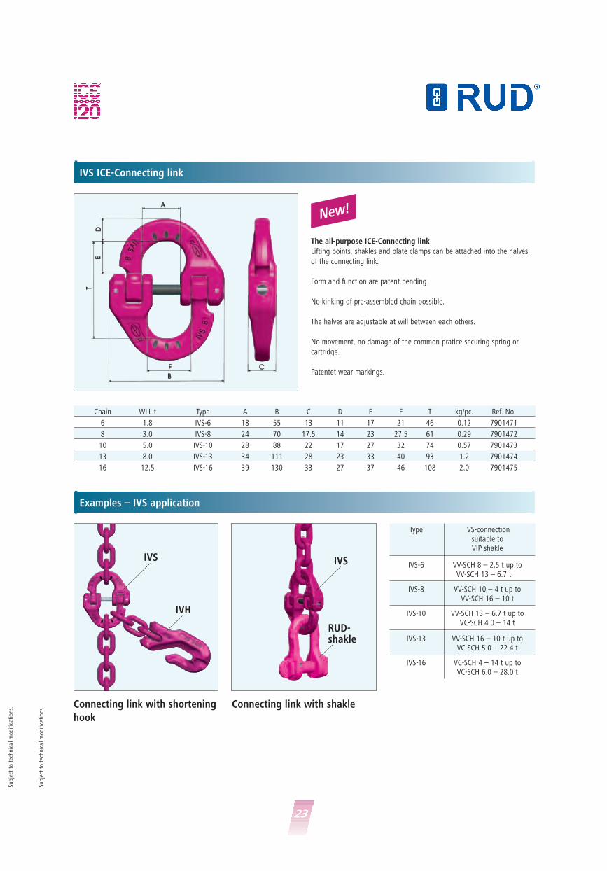
IVS ICE-Connecting link
Examples – IVS application
The all-purpose ICE-Connecting link
Lifting points, shakles and plate clamps can be attached into the halves
of the connecting link.
Form and function are patent pending
No kinking of pre-assembled chain possible.
The halves are adjustable at will between each others.
No movement, no damage of the common pratice securing spring or
cartridge.
Patentet wear markings.
Chain WLL t Type A B C D E F T kg/pc. Ref. No.
6 1.8 IVS-6 18 55 13 11 17 21 46 0.12 7901471
8 3.0 IVS-8 24 70 17.5 14 23 27.5 61 0.29 7901472
10 5.0 IVS-10 28 88 22 17 27 32 74 0.57 7901473
13 8.0 IVS-13 34 111 28 23 33 40 93 1.2 7901474
16 12.5 IVS-16 39 130 33 27 37 46 108 2.0 7901475
Connecting link with shortening
hook
Connecting link with shakle
IVS
RUD-shakle
Type IVS-connectionsuitable toVIP shakle
IVS-6 VV-SCH 8 – 2.5 t up toVV-SCH 13 – 6.7 t
IVS-8 VV-SCH 10 – 4 t up toVV-SCH 16 – 10 t
IVS-10 VV-SCH 13 – 6.7 t up toVC-SCH 4.0 – 14 t
IVS-13 VV-SCH 16 – 10 t up toVC-SCH 5.0 – 22.4 t
IVS-16 VC-SCH 4 – 14 t up toVC-SCH 6.0 – 28.0 t
New!
Subj
ect
to t
echn
ical
mod
ifica
tion
s.
Subj
ect
to t
echn
ical
mod
ifica
tion
s.
IVS
IVH
24
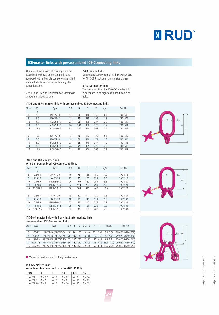
ICE-master links with pre-assembled ICE-Connecting links
All master links shown at this page are pre-
assembled with ICE-Connecting links and
equipped with a flexible complete assembled,
stamped identification tag with integrated
gauge function.
Size 13 and 16 with universal-KZA identificati-
on tag and added gauge.
ISAK master links
Dimensions comply to master link type A acc.
to DIN 5688, but one nominal size bigger.
ISAK-IVS master links
The inside width of the ISAK-SC master links
is adequate to fit high tensile load hooks of
hoists.
Chain WLL Type Ø A B C T kg/pc. Ref. No.
t
6 1.8 IAK-IVS-1-6 13 60 110 155 0.6 7901508
8 3.0 IAK-IVS-1-8 18 75 135 196 1.3 7901509
10 5.0 IAK-IVS-1-10 22 90 160 234 2.2 7901510
13 8.0 IAK-IVS-1-13 26 100 180 273 3.4 7901511
16 12.5 IAK-IVS-1-16 32 140 260 368 7.4 7901512
6 1.8 IBK-IVS-1-6 13 40 85 130 0.5 7901513
8 3.0 IBK-IVS-1-8 18 60 110 171 1.2 7901514
10 5.0 IBK-IVS-1-10 22 65 140 214 1.9 7901515
13 8.0 IBK-IVS-1-13 26 75 135 228 2.9 7901516
16 12.5 IBK-IVS-1-16 32 90 160 268 5.9 7901517
IAK-1 and IBK-1 master link with pre-assembled ICE-Connecting links
Chain WLL Type Ø A B C T kg/pc. Ref. No.
t
6 2.5/1.8 IAK-IVS-2-6 16 75 135 180 1.0 7901518
8 4.25/3.0 IAK-IVS-2-8 22 90 160 221 2.3 7901519
10 7.1/5.0 IAK-IVS-2-10 26 100 180 254 3.5 7901520
13 11.2/8.0 IAK-IVS-2-13 32 110 200 293 5.9 7901521
16 17.0/12.5 IAK-IVS-2-16 36 180 340 448 12.9 7901522
6 2.5/1.8 IBK-IVS-2-6 13 40 85 130 0.6 7901529
8 4.25/3.0 IBK-IVS-2-8 18 60 110 171 1.5 7901530
10 7.1/5.0 IBK-IVS-2-10 22 65 140 214 2.3 7901531
13 11.2/8.0 IBK-IVS-2-13 26 75 135 228 3.5 7901532
16 17.012.5 IBK-IVS-2-16 32 90 160 268 7.9 7901533
IAK-2 and IBK-2 master link
with 2 pre-assembled ICE-Connecting links
IAK-3-/-4 master link with 3 or 4 in 2 intermediate links
pre-assembled ICE-Connecting links
Chain WLL Type Ø A B C Ø D E F T kg/pc. Ref. No.
t
6 3.75/2.7 IAK-IVS-4-6 (IAK-IVS-3-6) 18 90 160 13 40 85 290 3.1 (3.0) 7901534 (7901539)
8 6.3/4.5 IAK-IVS-4-8 (IAK-IVS-3-8) 26 100 180 18 60 110 351 5.2 (4.9) 7901535 (7901540)
10 10.6/7.5 IAK-IVS-4-10 (IAK-IVS-3-10) 32 110 200 22 65 140 414 8.7 (8.3) 7901536 (7901541)
13 17.0/11.8 IAK-IVS-4-13 (IAK-IVS-3-13) 36 140 260 26 75 135 488 13.4 (12.7) 7901537 (7901542)
16 26.5/19.0 IAK-IVS-4-16 (IAK-IVS-3-16) 46 190 350 32 90 160 618 28.9 (26.9) 7901538 (7901543)
IAK-IVS-master linkssuitable up to crane hook size no. (DIN 15401)
� Values in brackets are for 3 leg master links
Size 6 8 10 13 16
IAK-IVS 1 No. 2.5 No. 5 No. 6 No. 8 No. 16IAK-IVS 2 No. 5 No. 6 No. 8 No. 10 No. 25IAK-IVS 3/4 No. 6 No. 8 No. 10 No. 16 No. 32 Su
bjec
t to
tec
hnic
al m
odifi
cati
ons.
Subj
ect
to t
echn
ical
mod
ifica
tion
s.
25
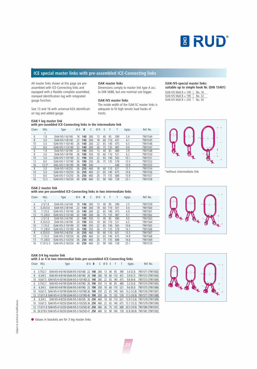
All master links shown at this page are pre-
assembled with ICE-Connecting links and
equipped with a flexible complete assembled,
stamped identification tag with integrated
gauge function.
Size 13 and 16 with universal-KZA identificati-
on tag and added gauge.
ISAK master links
Dimensions comply to master link type A acc.
to DIN 5688, but one nominal size bigger.
ISAK-IVS master links
The inside width of the ISAK-SC master links is
adequate to fit high tensile load hooks of
hoists.
ICE special master links with pre-assembled ICE-Connecting links
ISAK-IVS-special master links:suitable up to simple hook Nr. (DIN 15401)
ISAK-IVS Maß B = 140 No. 16
ISAK-IVS Maß B = 190 No. 32
ISAK-IVS Maß B = 250 No. 50
ISAK-1 leg master linkwith pre-assmbled ICE-Connecting links in the intermediate link
Chain WLL Type Ø A B C Ø D E F T kg/pc. Ref. No.t
6 1.8 ISAK-IVS-1-6/140 18 140 260 13 40 85 390 2.4 79015448 3.0 ISAK-IVS-1-8/140 22 140 260 18 60 110 431 4.1 790154510 5.0 ISAK-IVS-1-10/140 26 140 260 22 65 140 475 6.5 790154613 8.0 ISAK-IVS-1-13/140 32 140 260 26 75 135 487 9.0 79015476 1.8 ISAK-IVS-1-6/190 22 190 350 13 40 85 480 3.9 79015488 3.0 ISAK-IVS-1-8/190 26 190 350 18 60 110 521 6.2 790155010 5.0 ISAK-IVS-1-10/190 32 190 350 22 65 140 565 10.1 790155113 8.0 ISAK-IVS-1-13/190 36 190 350 26 75 135 578 13.5 790155216 12.5* IAKL-IVS-1-16/190 36 180 340 - - - 448 10.9 79015538 3.0 ISAK-IVS-1-8/250 36 250 460 18 60 110 631 13.1 790155410 5.0 ISAK-IVS-1-10/250 36 250 460 22 65 140 675 14.6 790155613 8.0 ISAK-IVS-1-13/250 36 250 460 26 75 135 688 15.9 790155716 12.5 ISAK-IVS-1-16/250 40 250 460 32 90 160 728 23.1 7901558
ISAK-2 master linkwith one pre-assembled ICE-Connecting links in two intermediate links
ISAK-3/4 leg master linkwith 3 or 4 in two intermediat links pre-assembled ICE-Connecting links
Chain WLL Type Ø A B C Ø D E F T kg/pc. Ref. No.
t
6 3.75/2.7 ISAK-IVS-4-6/140 (ISAK-IVS-3-6/140) 22 140 260 13 40 85 390 3.4 (3.3) 7901571 (7901582)
8 6.3/4.5 ISAK-IVS-4-8/140 (ISAK-IVS-3-8/140) 26 140 260 18 60 110 431 5.9 (5.7) 7901572 (7901583)
10 10.6/7.5 ISAK-IVS-4-10/140 (ISAK-IVS-3-10/140) 32 140 260 22 65 140 475 9.8 (9.4) 7901573 (7901584)
6 3.75/2.7 ISAK-IVS-4-6/190 (ISAK-IVS-3-6/190) 26 190 350 13 40 85 480 5.5 (5.4) 7901574 (7901585)
8 6.3/4.5 ISAK-IVS-4-8/190 (ISAK-IVS-3-8/190) 32 190 350 18 60 110 521 9.6 (9.3) 7901575 (7901586)
10 10.6/7.5 ISAK-IVS-4-10/190 (ISAK-IVS-3-10/190) 36 190 350 22 65 140 565 13.2 (12.8) 7901576 (7901587)
13 17.0/11.8 ISAK-IVS-4-13/190 (ISAK-IVS-3-13/190) 40 190 350 26 75 135 578 17.5 (16.9) 7901577 (7901588)
8 6.3/4.5 ISAK-IVS-4-8/250 (ISAK-IVS-3-8/250) 36 250 460 18 60 110 631 13.9 (13.6) 7901578 (7901589)
10 10.6/7.5 ISAK-IVS-4-10/250 (ISAK-IVS-3-10/250) 36 250 460 22 65 140 675 15.7 (15.3) 7901579 (7901590)
13 17.0/11.8 ISAK-IVS-4-13/250 (ISAK-IVS-3-13/250) 40 250 460 26 75 135 688 20.5 (19.9) 7901580 (7901591)
16 26.5/19.0 ISAK-IVS-4-16/250 (ISAK-IVS-3-16/250) 47 250 460 32 90 160 728 32.8 (30.8) 7901581 (7901592)
Chain WLL Type Ø A B C Ø D E F T kg/pc. Ref. No.t
6 2.5/1.8 ISAK-IVS-2-6/140 18 140 260 13 40 85 390 2.5 79015598 4.25/3.0 ISAK-IVS-2-8/140 22 140 260 18 60 110 431 4.4 790156010 7.1/5.0 ISAK-IVS-2-10/140 26 140 260 22 65 140 475 6.9 790156113 11.2/8.0 ISAK-IVS-2-13/140 32 140 260 26 75 135 487 9.7 79015626 2.5/1.8 ISAK-IVS-2-6/190 22 190 350 13 40 85 480 4.0 79015638 4.25/3.0 ISAK-IVS-2-8/190 26 190 350 18 60 110 521 6.5 790156410 7.1/5.0 ISAK-IVS-2-10/190 32 190 350 22 65 140 565 10.6 790156513 11.2/8.0 ISAK-IVS-2-13/190 36 190 350 26 75 135 578 14.1 79015668 4.25/3.0 ISAK-IVS-2-8/250 36 250 460 18 60 110 631 13.3 790156710 7.1/5.0 ISAK-IVS-2-10/250 36 250 460 22 65 140 675 14.9 790156813 11.2/8.0 ISAK-IVS-2-13/250 36 250 460 26 75 135 688 16.6 790156916 17.0/12.5 ISAK-IVS-2-16/250 40 250 460 32 90 160 728 25.1 7901570
� Values in brackets are for 3 leg master links
Subj
ect
to t
echn
ical
mod
ifica
tion
s.
*without intermediate link
26
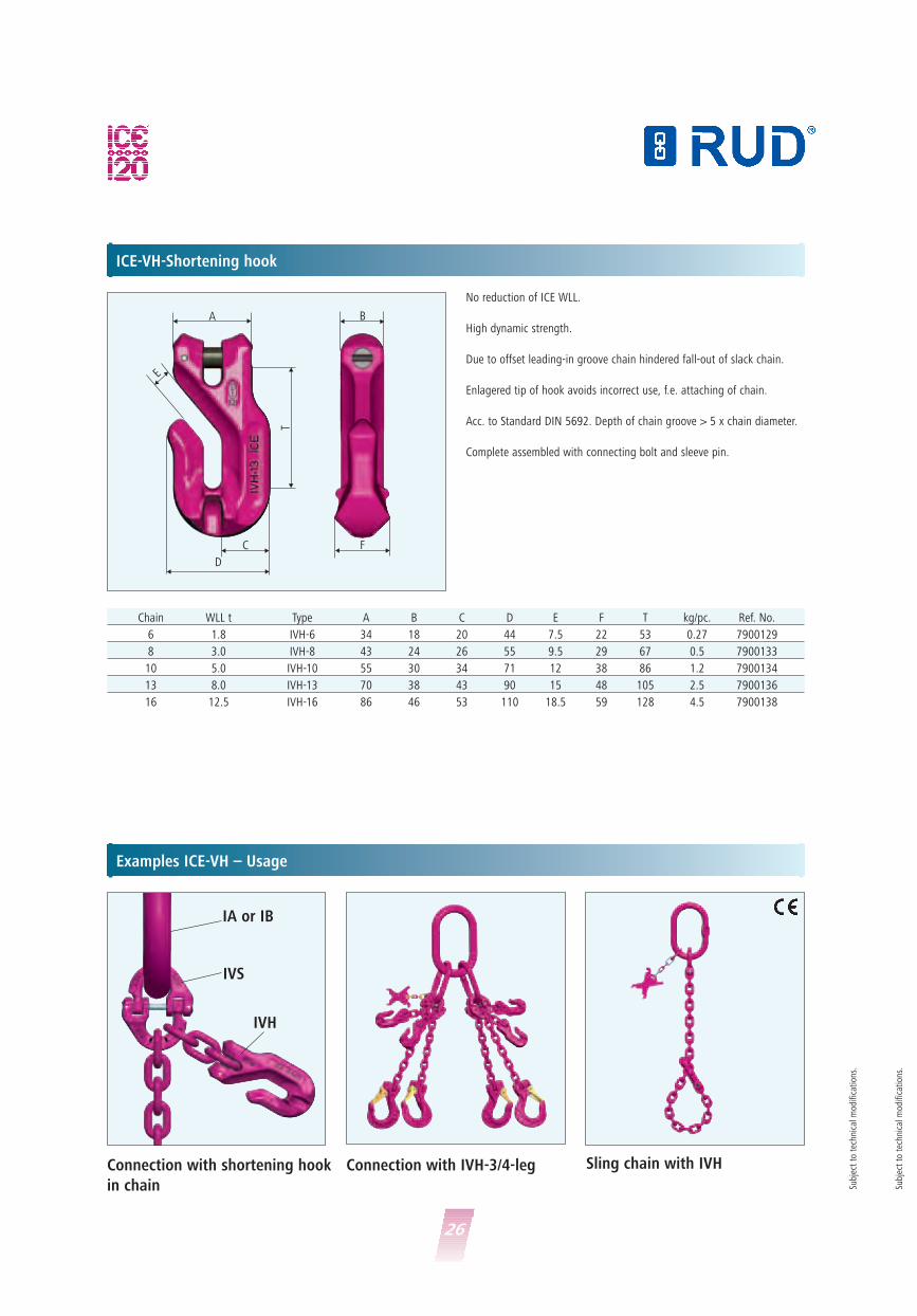
ICE-VH-Shortening hook
Examples ICE-VH – Usage
Chain WLL t Type A B C D E F T kg/pc. Ref. No.
6 1.8 IVH-6 34 18 20 44 7.5 22 53 0.27 7900129
8 3.0 IVH-8 43 24 26 55 9.5 29 67 0.5 7900133
10 5.0 IVH-10 55 30 34 71 12 38 86 1.2 7900134
13 8.0 IVH-13 70 38 43 90 15 48 105 2.5 7900136
16 12.5 IVH-16 86 46 53 110 18.5 59 128 4.5 7900138
No reduction of ICE WLL.
High dynamic strength.
Due to offset leading-in groove chain hindered fall-out of slack chain.
Enlagered tip of hook avoids incorrect use, f.e. attaching of chain.
Acc. to Standard DIN 5692. Depth of chain groove > 5 x chain diameter.
Complete assembled with connecting bolt and sleeve pin.
� �
�
�
��
�
��
�
�
�
C F
T
��BA
E
D
Subj
ect
to t
echn
ical
mod
ifica
tion
s.
Subj
ect
to t
echn
ical
mod
ifica
tion
s.
Sling chain with IVHConnection with shortening hook
in chain
Connection with IVH-3/4-leg
IVS
IA or IB
IVH
27
Subj
ect
to t
echn
ical
mod
ifica
tion
s.
�
�
�
�
�
�
�
�
�
�
�
�
�
��
�
��
T1
BT2
��
T
EF
A
B DC
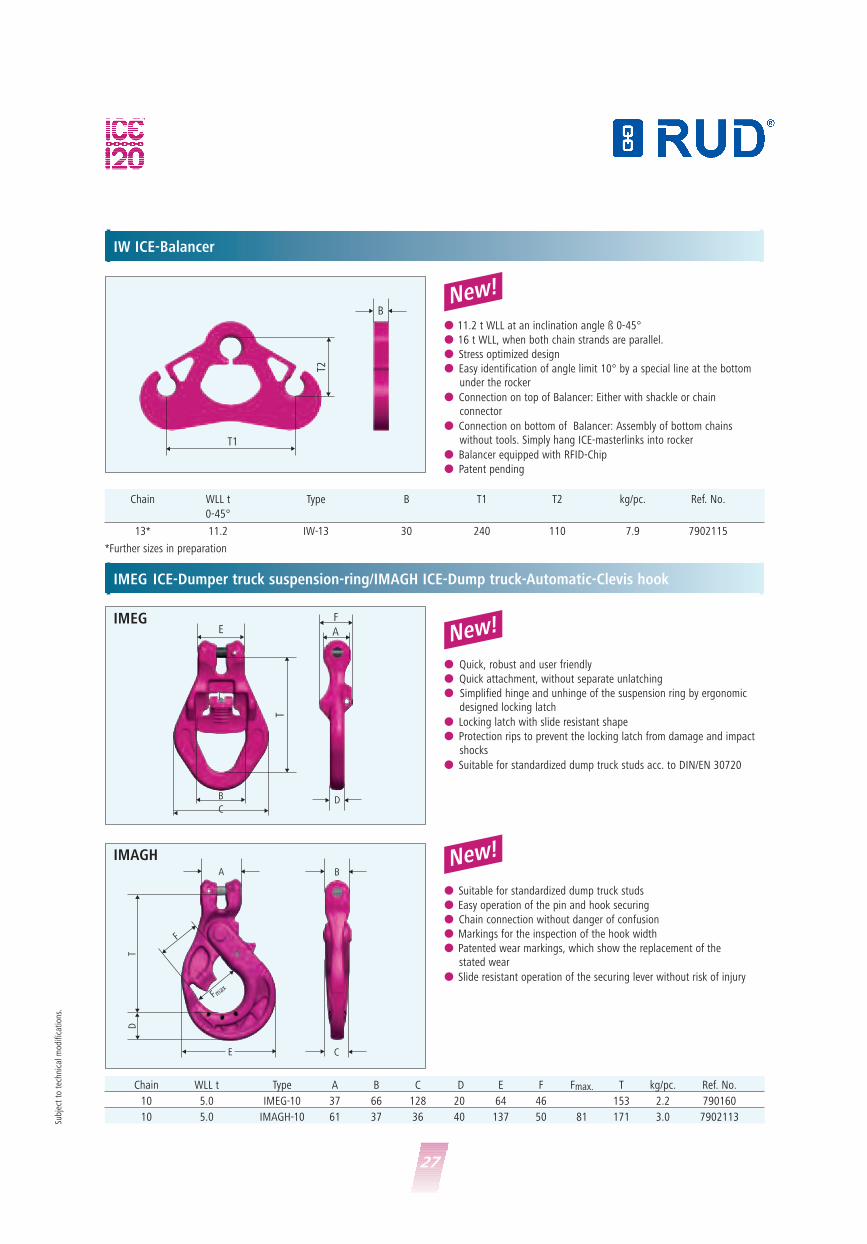
IW ICE-Balancer
IMEG ICE-Dumper truck suspension-ring/IMAGH ICE-Dump truck-Automatic-Clevis hook
New!
New!
� 11.2 t WLL at an inclination angle ß 0-45°
� 16 t WLL, when both chain strands are parallel.
� Stress optimized design
� Easy identification of angle limit 10° by a special line at the bottom under the rocker
� Connection on top of Balancer: Either with shackle or chain connector
� Connection on bottom of Balancer: Assembly of bottom chains without tools. Simply hang ICE-masterlinks into rocker
� Balancer equipped with RFID-Chip
� Patent pending
� Quick, robust and user friendly
� Quick attachment, without separate unlatching
� Simplified hinge and unhinge of the suspension ring by ergonomic designed locking latch
� Locking latch with slide resistant shape
� Protection rips to prevent the locking latch from damage and impactshocks
� Suitable for standardized dump truck studs acc. to DIN/EN 30720
New!
� Suitable for standardized dump truck studs
� Easy operation of the pin and hook securing
� Chain connection without danger of confusion
� Markings for the inspection of the hook width
� Patented wear markings, which show the replacement of the stated wear
� Slide resistant operation of the securing lever without risk of injury
Chain WLL t Type B T1 T2 kg/pc. Ref. No.
0-45°
13* 11.2 IW-13 30 240 110 7.9 7902115
*Further sizes in preparation
Chain WLL t Type A B C D E F Fmax. T kg/pc. Ref. No.
10 5.0 IMEG-10 37 66 128 20 64 46 153 2.2 790160
10 5.0 IMAGH-10 61 37 36 40 137 50 81 171 3.0 7902113
IMEG
��
��
�
�
��
��
�
�
BA
F
Fmax
��
��
CE
TD
IMAGH
28
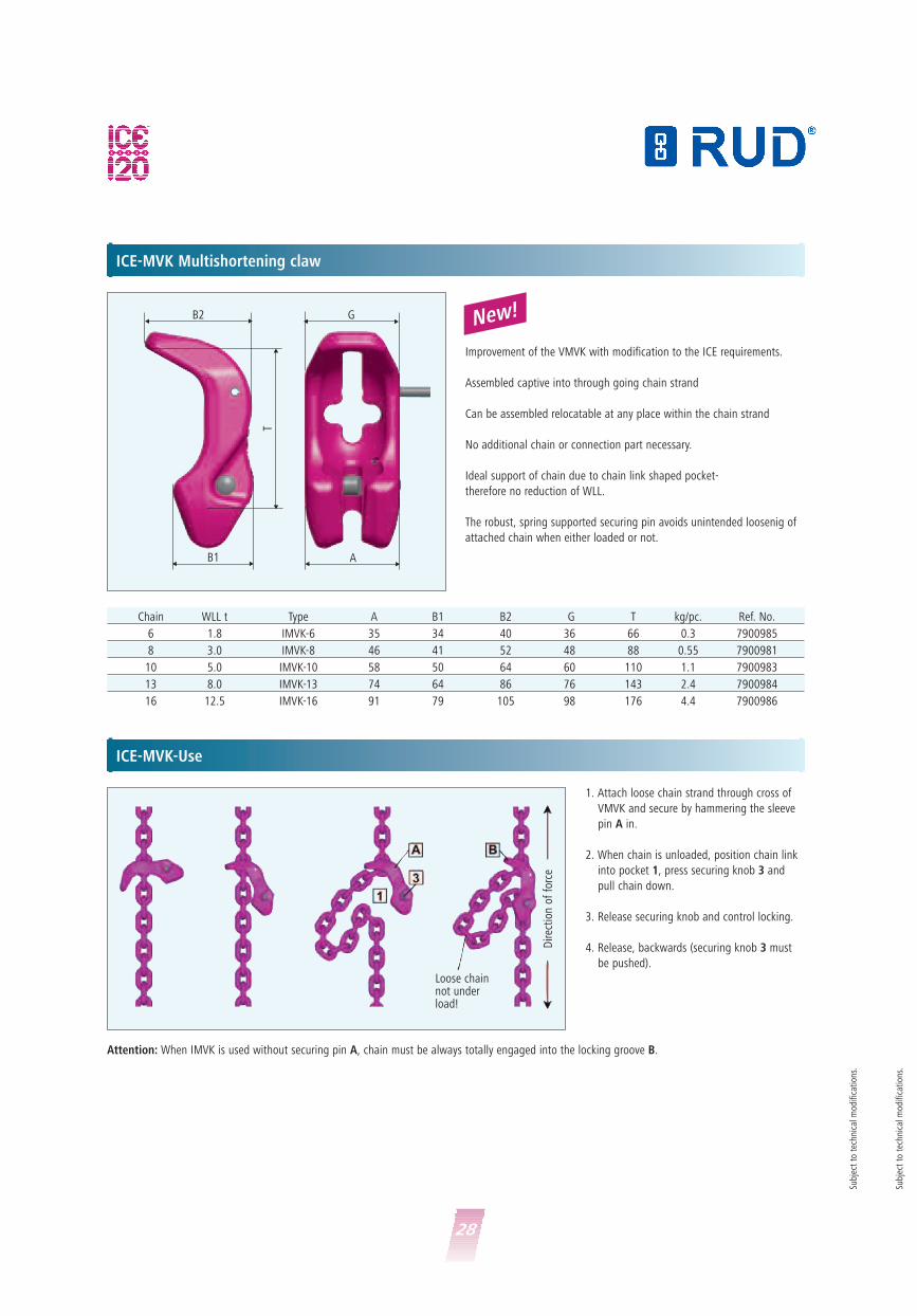
ICE-MVK Multishortening claw
ICE-MVK-Use
Improvement of the VMVK with modification to the ICE requirements.
Assembled captive into through going chain strand
Can be assembled relocatable at any place within the chain strand
No additional chain or connection part necessary.
Ideal support of chain due to chain link shaped pocket-
therefore no reduction of WLL.
The robust, spring supported securing pin avoids unintended loosenig of
attached chain when either loaded or not.
� �
�
��
�
��A
T
��B2 G
B1
Chain WLL t Type A B1 B2 G T kg/pc. Ref. No.
6 1.8 IMVK-6 35 34 40 36 66 0.3 7900985
8 3.0 IMVK-8 46 41 52 48 88 0.55 7900981
10 5.0 IMVK-10 58 50 64 60 110 1.1 7900983
13 8.0 IMVK-13 74 64 86 76 143 2.4 7900984
16 12.5 IMVK-16 91 79 105 98 176 4.4 7900986
1. Attach loose chain strand through cross of
VMVK and secure by hammering the sleeve
pin A in.
2. When chain is unloaded, position chain link
into pocket 1, press securing knob 3 and
pull chain down.
3. Release securing knob and control locking.
4. Release, backwards (securing knob 3 must
be pushed).
Attention: When IMVK is used without securing pin A, chain must be always totally engaged into the locking groove B.
Loose chainnot underload!
Dire
ctio
n of
for
ce
Subj
ect
to t
echn
ical
mod
ifica
tion
s.
Subj
ect
to t
echn
ical
mod
ifica
tion
s.
New!

29
ICE-CURT ratched tensioner for lifting – light and robust
ICE-CURT-GAKO/ICE-CURT-SL
Practice friendly turn-loose securing, providing
theft protection done by padlock (e.g. type
ABUS 85/40 HB ), 100 % crack inspected, all
parts drop forged.
Easy to clean and lubricate, innovative forged
design-light in weight and robust, Patent
pending.
Made in Germany, user friendly – even with
gloves.
ICE-T-GAKO*
With clevis connection, inside positioned
thread, lubrication nipple.
� For an exact length adjustment on a chain sling.
� Due to right/left thread on the ratchet, adjustments to the mm can be
performed.
� Under load, it is only possible to elongate the chain strand.
In 8 and 10 also possible with shortening latch (SL).
Millimeter accurate length adjustement with ICE-CURT
�
�
�
�
�
�
L = openL = open
L = closed L = closed
L = open
L = closed �
�
Chain Ø Type Lashing L-open L-closed Reach Weight Ref. No.WLL [mm] [mm] [mm] [kg/pc.][t]
6 ICE-CURT 6-SL 1.8
6 ICE-CURT-6-GAKO 1.8
8 ICE-CURT-8-SL 3.0 623 453 170 4.5 7999435
8 ICE-CURT-8-GAKO 3.0 520 350 170 3.9 7901125
10 ICE-CURT-10-SL 5.0 671 501 170 5.2 7999436
10 ICE-CURT-10-GAKO 5.0 532 362 170 4.3 7901126
13 ICE-T-GAKO-13* 8.0 695 445 250 7.5 7995935
13 ICE-CURT-13-GAKO 8.0
16 ICE-CURT-16-GAKO 12.5
*Model expires (as long as stock lasts)
ICE-CURT-GAKO ICE-T-GAKO*ICE-CURT-SL
in preperation
in preperation
in preperation
in preperation
Subj
ect
to t
echn
ical
mod
ifica
tion
s.

30
ICE-SH ICE Star Hook
Chain WLL t Type A B C D F Fmax. G T kg/pc. Ref. No.
6 1.8 ICE-SH-6 48 28 18 26 30 51 97 97 0.69 7998179
8 3.0 ICE-SH-8 45 36 20 29 36 58 112 110 1.1 7995254
10 5.0 ICE-SH-10 56 43 25 37 41 66 135 127 1.9 7995255
13 8.0 ICE-SH-13 85 52 31 48 50 80 163 153 3.5 7995256
16 12.5 ICE-SH-16 94 58 38 56 58 96 196 184 5.5 7995257
Safety Set
Consisting of a forged
safety latch, triple-
coiled corrosion pro-
tected double-leg
spring and a retaining
pin.
Only available as a
complete set.
Easy assembly and
removal using only
hammer and drift
punch.
Use only
original RUD-ICE
spare parts!
Chain Type kg/pc. Ref. No.
6 Si-Set ICE-SH-6 0.09 7100300
8 Si-Set ICE-SH-8 0.11 7100301
10 Si-Set ICE-SH-10 0.15 7100302
13 Si-Set ICE-SH-13 0.24 7100303
16 Si-Set ICE-SH-16 0.40 7900419
ICE Star Hook – suitable down to -60°C.
Due to its innovative construction, the skeletal design ICE-SH Star Hook
is up to 25 % lighter than Grade 80 hooks of the same WLL, i.e. the next
larger size.
The large width of the throat of the hook is the same dimensionally as
the million fold successful Granit-Super Hook – of the next larger size –
so not everything was reduced!
The safety latch of the RUD-Hook family, the GSH, SH,
Cobra and ICE-Star Hook are interchangeable.
(Make sure to select the correct diameter) –
easy to supply spare parts.
All the benefits of the VIP-Cobra-Hook are inclu-
ded and improved:
� Marker points to check the width of the hook on inspection – (often copied)!
� Patented wear marks that, without measuring, show instantly whenthe hook has reached the statutory allowable wear limit and must be replaced
� Forged, tempered and ergonomic safety latch with a triple-coiled, double-leg spring in stainless steel. Exceeds by far, the EN standard values for side loading
� Edge protection – increased section at the side and top of the hook
for the safety latch
� Wear ribs – which protect the first chain link into the clevis
� No protruding hook tip
� Thickened tip of the hook – prevents incorrect and dangerous use of the hook tip
Subj
ect
to t
echn
ical
mod
ifica
tion
s.

31
ICE-AGH ICE-Clevis self locking hook
IAGH – suitable to -60°C.
Due to it’s innovative construction, the skeletal design ICE-SH Star Hook
is up to 25 % lighter than Grade 8 hooks of the same WLL, i.e. the next
larger size.
The large width of the throat of the hook is the same dimensionally as
the Grade 80 hook – so not everything was reduced!
Locking device designed ergonomically, easy to handle with anti-slip sur-
face – no danger of bruise.
Chain WLL t Type A B C D E F Fmax. T kg/pc. Ref. No.
6 1.8 IAGH-6 34 24 27 28 97 44 60 113 0.9 7900085
8 3.0 IAGH-8 45 31 30 31 106 48 66 124 1.2 7997691
10 5.0 IAGH-10* 50 38 36 40 136 61 81 154 2.4 7997692
13 8.0 IAGH-13 73 50 44 51 173 78 107 200 4.9 7997693
16 12.5 IAGH-16 90 61 49 53 192 85 121 232 7.4 7900086
� Thickened tip of the hook – prevents incorrect and dangerous use of the hook tip
� Proven marker points to check the width of the hook on inspection – (often copied)!
� Patented wear marks that, without measuring, show instantly whenthe hook has reached the statutory allowed.
� Wear ribs (dim. “B”) which protect the first chain link into the clevis.
Safety Set
Chain Type kg/pc. Ref. No.
6 Si-Set IAGH-6 0.03 8503759
8 Si-Set IAGH-8 0.04 8503713
10 Si-Set IAGH-10 0.06 7998255
13 Si-Set IAGH-13 0.14 8503714
16 Si-Set IAGH-16 0.2 8503760
� Only available as a complete set
� Consisting of a locking device, a corrossion protected double-legspring and a tetaining pin
� Easy assembly and removal using only hammer and drift punch
Use only
original RUD-ICE
spare parts!
Subj
ect
to t
echn
ical
mod
ifica
tion
s.
Subj
ect
to t
echn
ical
mod
ifica
tion
s.
*For applications at dump trucks see page 27 IMAGH-10.

32
The strongest ICE-Lashing chain
Subj
ect
to t
echn
ical
mod
ifica
tion
s.
The proven, technical advantages of the VIP-program have been retained and further impro-ved. Tensioning, connecting and shortening element have been improved considerably inweight and functionality.
ICE – in ICE-Pink (traffic purple) powder coated– means significant weight saving for the user.The standard equivalent Grade 80 commerciallashing chains are on average 60 % heavier.
This improved ergonomic design, enables fasterfitting and heightened safety.
It is possible to use one diameter smaller than Grade 80 <16 mm Ø.
Up to 60 % higher Lashing Capacity (LC) thanGrade 80 – also up to -60°C even in Arcticapplications.
All values (conditions) of EN 12195-3 are fulfil-led and the essential requirements are easilyexceeded. All for the health and safety of theuser!
ICE-CURTRatched tensioner version with an integratedfast shortener, which is assembled captive inthe chain strand. As an alternative there is aclevis type available also.
Patented:“Secured against release by a magnet blockingclutch which can be secured with a lock. Theftprotection of lashing chain and transportinggoods.”
Thread tube now in a open and innovative form– robust, light in weight and due to the trape-zoid thread easy to clean, check and lubricate.
Made in Germany.
All pieces drop forged, quentched and tempe-red and 100 % crack inspected.
33
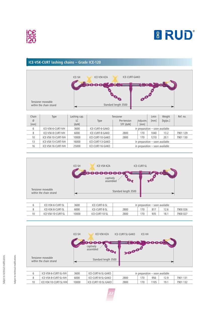
ICE-VSK-CURT lashing chains – Grade ICE-120
Chain Type Lashing cap. Lmin Weight Ref. no.
Ø LC Type Pre-tension Adjustm. [mm] [kg/pc.]
[mm] [daN] STF [daN] [mm]
6 ICE-VSK-6-CURT-IVH 3600 ICE-CURT-6-GAKO in preparation – soon available
8 ICE-VSK-8-CURT-IVH 6000 ICE-CURT-8-GAKO 2800 170 1040 13.2 7901 129
10 ICE-VSK-10-CURT-IVH 10000 ICE-CURT-10-GAKO 2800 170 1210 20.1 7901 130
13 ICE-VSK-13-CURT-IVH 16000 ICE-CURT-13-GAKO in preparation – soon available
16 ICE-VSK-16-CURT-IVH 25000 ICE-CURT-16-GAKO in preparation – soon available
Tensioner
6 ICE-VSK-6-CURT-SL 3600 ICE-CURT-6-SL in preparation – soon available
8 ICE-VSK-8-CURT-SL 6000 ICE-CURT-8-SL 2800 170 817 12.6 7900 026
10 ICE-VSK-10-CURT-SL 10000 ICE-CURT-10-SL 2800 170 935 18.1 7900 027
ICE-SH ICE-VSK-KZA
Standard length 3500
captivelyassembled
ICE-CURT-SL
Tensioner moveablewithin the chain strand
Standard length 3500
ICE-SH ICE-VSK-KZA ICE-CURT-GAKO
Tensioner moveablewithin the chain strand
6 ICE-VSK-6-CURT-SL-IVH 3600 ICE-CURT-6-SL-GAKO in preparation – soon available
8 ICE-VSK-8-CURT-SL-IVH 6000 ICE-CURT-8-SL-GAKO 2800 170 956 12.9 7901 131
10 ICE-VSK-10-CURT-SL-IVH 10000 ICE-CURT-10-SL-GAKO 2800 170 1105 19.1 7901 132
ICE-SH ICE-VSK-KZA
Standard length 3500
captivelyassembled
ICE-CURT-SL-GAKO ICE-VH
Tensioner moveablewithin the chain strand
Subj
ect
to t
echn
ical
mod
ifica
tion
s.
Subj
ect
to t
echn
ical
mod
ifica
tion
s.
34
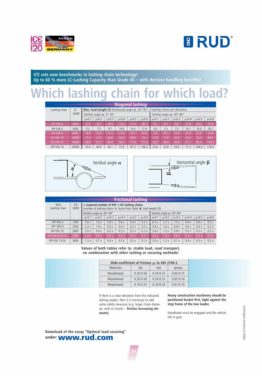
ICE sets new benchmarks in lashing chain technology!Up to 60 % more LC-Lashing Capacity than Grade 80 – with decisive handling benefits!
Which lashing chain for which load?Lashing chain LC
[daN]
μ=0.1 μ=0.2 μ=0.3 μ=0.4 μ=0.5 μ=0.6 μ=0.1 μ=0.2 μ=0.3 μ=0.4 μ=0.5 μ=0.6
ICE-VSK 6 3600 6.2 8.4 10.4 13.0 17.4 26.2 4.5 6.3 9.0 12.8 19.2 32.0
VIP-VSK 6 3000 5.2 7.0 8.7 10.9 14.5 21.9 3.8 5.3 7.5 10.7 16.0 26.7
ICE-VSK 8 6000 10.5 14.0 17.4 21.8 29.1 43.9 7.6 10.7 15.0 21.4 32.0 53.4
ICE-VSK 10 10000 17.5 23.4 29.0 36.4 48.6 73.1 12.8 17.9 25.0 35.6 53.4 89.0
ICE-VSK 13 16000 28.0 37.5 46.4 58.2 77.8 117.0 20.5 28.6 40.0 57.1 85.5 142.4
VIP-VSK 16 20000 35.0 46.9 58.1 72.8 97.3 146.3 25.6 35.8 50.0 71.3 106.9 178.0
Max. load weight [t] (horizontal angle �: 20°-45°; 2 lashing chains per direction)
Vertikal angle �: 0°-30° Vertikal angle �: 30°-60°
STF[daN]
μ=0.1 μ=0.2 μ=0.3 μ=0.4 μ=0.5 μ=0.6 μ=0.1 μ=0.2 μ=0.3 μ=0.4 μ=0.5 μ=0.6
VIP-VSK 6 1500 3.6 x 1.6 x 0.9 x 0.6 x 0.4 x 0.2 x 6.3 x 2.7 x 1.5 x 0.9 x 0.6 x 0.3 x
2500 2.2 x 1.0 x 0.6 x 0.4 x 0.2 x 0.2 x 3.8 x 1.6 x 0.9 x 0.6 x 0.4 x 0.2 x
VIP-VSK 10 2800 2.0 x 0.9 x 0.5 x 0.3 x 0.2 x 0.1 x 3.4 x 1.5 x 0.8 x 0.5 x 0.3 x 0.2 x
ICE-VSK 8/10/13 2800 2.0 x 0.9 x 0.5 x 0.3 x 0.2 x 0.1 x 3.4 x 1.5 x 0.8 x 0.5 x 0.3 x 0.2 x
VIP-VSK 13/16 3600 1.5 x 0.7 x 0.4 x 0.3 x 0.2 x 0.1 x 2.6 x 1.2 x 0.7 x 0.4 x 0.3 x 0.2 x
= required number of VIP + ICE lashing chains(number of lashing chains = factor from Table x load weight [t])
Vertikal angle �: 60°-90° Vertikal angle �: 30°-60°
Diagonal lashing
Frictional lashingRUD
Lashing chain
VIP- VSK 8
Materials dry wet greasy
Wood/wood 0.20-0.50 0.20-0.25 0.05-0.15
Metal/wood 0.20-0.50 0.20-0.25 0.02-0.10
Metal/metal 0.10-0.25 0.10-0.20 0.01-0.10
Slide-coefficient of friction � to VDI 2700-2
Download of the essay “Optimal load securing”
under: www.rud.com
�
�Vertikal angle � Horizontal angle �
If there is a clear deviation from the indicated
lashing angles, then it is necessary to add
some safety measures (e.g. larger chain diame-
ter, and/ or chocks – friction increasing ele-
ments).
Heavy construction machinery should be
positioned bucket first, tight against the
step frame of the low loader.
Handbrake must be engaged and the vehicle
left in gear.
Subj
ect
to t
echn
ical
mod
ifica
tion
s.
Values of both tables refer to: stable load, road transport, no combination with other lashing or securing methods!

35
Locking device opened Locking device closed Locking device closed and secured
against thefts
For the user of ICE-lashing chains,this offers a treamendous weightsaving, improved ergonomics, quickerinstallation and more safety.
The ICE-CURT comes with an magnetic adhensioning blocking clutch which
is a securing device against release.
ICE-CURT Ratched tensioner for lashing
Chain Ø Type Lashing cap. L-open L-closed Reach Pretension Weight Ref. No.LC [mm] [mm] [mm] STF [daN] [kg/pc.]
[daN] [kp]
6 ICE-CURT 6-SL 3.600
6 ICE-CURT-6-GAKO 3.600
6 ICE-CURT-6-SL-GAKO 3.600
8 ICE-CURT-8-SL 6.000 623 453 170 2.800 4.5 7999435
8 ICE-CURT-8-GAKO 6.000 520 350 170 2.800 3.9 7901125
8 ICE-CURT-8-SL-GAKO 6.000 575 405 170 2.800 4.7 7901127
10 ICE-CURT-10-SL 10.000 671 501 170 2.800 5.2 7999436
10 ICE-CURT-10-GAKO 10.000 532 362 170 2.800 4.3 7901126
10 ICE-CURT-10-SL-GAKO 10.000 605 435 170 2.800 4.8 7901128
13 ICE-T-GAKO-13* 16.000 695 445 250 2.800 7.5 7995935
13 ICE-CURT-13-GAKO 16.000
16 ICE-CURT-16-GAKO 25.000
*Model expires (as long as stock lasts)
in preparation
in preparation
in preparation
in preparation
in preparation
Subj
ect
to t
echn
ical
mod
ifica
tion
s.
Subj
ect
to t
echn
ical
mod
ifica
tion
s.
�
�
�
�
�
�
L = openL = open
L = closed L = closed
L = open
L = closed �
�
ICE-CURT-GAKO ICE-T-GAKO*ICE-CURT-SL

36
Methodsof sling
1-leg 2-leg 3-4 leg endlesBasket sling
with choke
Grade 8+ VIP 1
ICE 12
Temperature
°C
Attention:WLL has to be reduced by 50 % when load isunsymmetrical!
PINKRUD-Quality in PINKGrade 80, Grade 100 (VIP) and WLL »in metric tons« of sling cAccording to inclination angle at symmetr
RUD quality grades
80 100 120�� �
8 128S 10
100 % 133 % 158 %100 % 133 % 158 %
WLL
inclination angle: � 0 0-45° > 45-60° 0-45° > 45-60° –
load factor 1.0 1.4 1.0 2.1 1.5 1.6
Diam. of chains Quality grade
Ø 4 VIP 0.63 0.88 0.63 1.32 0.95 1.0
Gk 8 1.12 1,6 1.12 2.36 1.7 1.8
Ø 6 VIP 1.5 2.1 1.5 3.15 2.25 2.4
ICE 1.8 2.5 1.8 3.75 2.7 2.88
Gk 8 2.0 2.8 2.0 4.25 3.0 3.2
Ø 8 VIP 2.5 3.5 2.5 5.25 3.75 4.0
ICE 3.0 4.2 3.0 6.3 4.5 4.8
Gk 8 3.15 4.25 3.15 6.7 4.75 5.0
Ø 10 VIP 4.0 5.6 4.0 8.4 6.0 6.4
ICE 5.0 7.0 5.0 10.5 7.5 8.0
Gk 8 5.3 7.5 5.3 11.2 8.0 8.5
Ø 13 VIP 6.7 9.5 6.7 14.0 10.0 10.6
ICE 8.0 11.2 8.0 16.8 12.0 12.8
Gk 8 8.0 11.2 8.0 17.0 11.8 12.5
Ø 16 VIP 10.0 14.0 10.0 21.0 15.0 16.0
ICE 12.5 17.0 12.5 26.5 19.0 20.0
Ø 18 Gk 8 10.0 14.0 10.0 21.0 15.0 16.0
Ø 20Gk 8 12.5 17.0 12.5 26.5 19.0 20.0
VIP 16.0 22.4 16.0 33.6 24.0 25.6
Ø 22Gk 8 15.0 21.2 15.0 31.5 22.4 23.6
VIP 20.0 28.0 20.0 42.0 30.0 32.0
Ø 26 Gk 8 21.2 30.0 21.2 45.0 31.5 33.5
Ø 28 VIP 31.5 45.0 31.5 67.0* 47.5* 50.0
Ø 32 Gk 8 31.5 45.0 31.5 67.0 47.5 50.0
Subject to technical modifications. *Only 2 x 2-leg type available.
100
®Grade
80
ICE-VH ICE-SC
ICE-Star Hook ICE-AGH
ICE-CURTICE-MVK

37
When sling chains are used in temperature higher 200°C (392°) the WLL has tobe reduced. WLL in % at chain temperature of
100 % 90 % 75 %
100 % 90 % 60 %
Basket sling chain* Choke hitch**endless*Basket sling chain
with choke hitch single singledouble double
**20 % reduction for basket chains,due to sharp edges,is considered.
Grade 80+ VIP 100
ICE 120
mperature
RUD KettenRieger & Dietz GmbH u. Co. KGFriedensinsel73432 Aalen/GermanyTel.: +49 7361 504-1316-1370-1224Fax: +49 7361 [email protected] · www.rud.com
„Made in Germany”
NK!NK!and Grade 120 (ICE)ing chainsmmetric loading
5-60° – 0-45° > 45-60° 0-45° > 45-60° 0° 0-45° > 45-60°
.5 1.6 1.1 0.8 1.7 1.2 0.8 1.1 0.8
95 1.0 0.69 0.5 1.1 0.75 0.5 0.69 0.5
.7 1.8 1.2 0.9 1.9 1.3 0.9 1.2 0.9
25 2.4 1.65 1.2 2.55 1.8 1.2 1.65 1.2
.7 2.88 2.0 1.44 3.1 2.1 1.44 2.0 1.44
.0 3.2 2.2 1.6 3.4 2.4 1.6 2.2 1.6
75 4.0 2.75 2.0 4.25 3.0 2.0 2.75 2.0
4.5 4.8 3.3 2.4 5.1 3.6 2.4 3.3 2.4
75 5.0 3.5 2.5 5.3 3.8 2.5 3.5 2.5
.0 6.4 4.4 3.2 6.8 4.8 3.2 4.4 3.2
.5 8.0 5.5 4.0 8.5 6.0 4.0 5.5 4.0
.0 8.5 5.8 4.0 9.0 6.0 4.0 5.8 4.0
0.0 10.6 7.5 5.3 11.2 8.0 5.3 7.5 5.3
2.0 12.8 8.8 6.4 13.6 9.6 6.4 8.8 6.4
1.8 12.5 8.8 6.4 13.6 9.6 6.4 8.8 6.4
5.0 16.0 11.0 8.0 17.0 12.0 8.0 11.0 8.0
9.0 20.0 14.0 10.0 21.2 15.0 10.0 14.0 10.0
5.0 16.0 11.0 8.0 17.0 12.0 8.0 11.0 8.0
9.0 20.0 14.0 10.0 21.2 15.0 10.0 14.0 10.0
4.0 25.6 17.6 12.8 27.2 19.2 12.8 17.6 12.8
2.4 23.6 16.5 12.0 25.5 18.0 12.0 16.5 12.0
0.0 32.0 22.0 16.0 34.0 24.0 16.0 22.0 16.0
1.5 33.5 23.3 17.0 36.0 25.4 17.0 23.0 17.0
7.5* 50.0 35.5 25.0 53.0* 37.5* 25.0 35.5 25.0
7.5 50.0 35.5 25.0 53.0 37.5 25.0 35.5 25.0
© A
lsto
m
-40° up to +200° C(-40° F up to +392° F)
higher 200° up to 300° C(higher 392° F up to 572° F)
higher 200° up to 250° C(higher 392° F up to 482° F)
higher 300° up to 400° C(higher 572° F up to 752° F)
higher 250° up to 300° C(higher 482° F up to 572° F)
-60° up to +200° C(-76° F up to +392° F)

38
The suitable range of modern and safe Lifting Points – for bolting
� All parts are either 100 % crack detected or proof loaded accord. to EN 1677.
� All original bolts from RUD are 100 % crackdetected.
� Safety factor 4 : 1 in any direction.� The types VRS, VRM and VLBG have to be
adjusted to the load direction.
� The types VRS, VRM and VLBG have to be adjusted to the load direction.
� RUD features such as clamping spring(VLBS) for noise reduction and distance lugsfor a perfect root pass weld increase theease of use.
� Low installation height, high dynamic andstatic strength.
� RUD Lifting Points are in accordance withDIN EN 818 and 1677 with a dynamic loading of more than 20.000 load cycles.
The BG recommends: At high dynamic appli-cations with high load cycles (permanent operation), the WLL must ber educed or askthe manufacturer.
Thread sizes
M 6-M150
Imperial(UNC,...) andspecial lengths
on request
VLBG – Load Ring (Vario)
Numb
er of
legs
Load
dire
ction
Type
PP-S
0.63
t
PP-S
1.5
t
PP-S
2.5
t
PP-S
4 t
PP-S
5 t
PP-S
8 t
VLBG
0.3
t
VLBG
0.6
3 t
VLBG
1 t
VLBG
1.5
t
VLBG
2.5
t
VLBG
4 t
VLBG
4 t
VLBG
5 t
VLBG
7 t
SPEC
.
VLBG
8 t
VLBG
10
t
VLBG
15
t
VLBG
20
t
LBG(
3) M
16 R
S 1t
LBG(
3) M
20 R
S 2t
Thre
ad si
ze
M12
M16
M20
M24
M30
M36
M8
M10
M12
M16
M20
M24
M27
M30
M36
M36
M42
M42
M48
M16
M20
1 0° 0.6 1.5 2.5 4 6.7 10 0.3 0.6 1 1.5 2.5 4 4 5 7 8 10 15 20 1 2
2 0° 1.2 3 5 8 13.4 20 0.6 1.2 2 3 5 8 8 10 14 16 20 30 40 2 4
1 90° 0.6 1.5 2.5 4 5 8 0.3 0.6 1 1.5 2.5 4 4 5 7 8 10 15 20 1 2
2 90° 1.2 3 5 8 10 16 0.6 1.2 2 3 5 8 8 10 14 16 20 30 40 2 4
20-
45°0.8 2.1 3.5 5.6 7.1 11.2 0.4 0.8 1.4 2.1 3.5 5.6 5.6 7 9.8 11.2 14 21 28 1.4 2.8
245-60°
0.6 1.5 2.5 4 5 8 0.3 0.6 1 1.5 2.5 4 4 5 7 8 10 15 20 1 2
2
unsy
mmetr
ical
0.6 1.5 2.5 4 5 8 0.3 0.6 1 1.5 2.5 4 4 5 7 8 10 15 20 1 2
3+40-
45°1.3 3.2 5.3 8.4 10.5 16.8 0.6 1.3 2.1 3.1 5.2 8.4 8.4 10.5 14.7 16.8 21 31.5 42 2.1 4.2
3+445-60°
0.9 2.2 3.8 6 7.5 12 0.4 0.9 2.2 2.2 3.7 6 6 7.5 10.4 12 15 22.5 30 1.5 3
3+4
unsy
mmetr
ical
0.6 1.5 2.5 4 5 8 0.3 0.6 1.5 1.5 2.5 4 4 5 7 8 10 15 20 1 2
Thre
ad si
ze
M12
M16
M20
M24
M30
M36
M8
M10
M12
M16
M20
M24
M27
M30
M36
M36
M42
M42
M48
M16
M20
PP-S (Vario)PowerPoint-Star
PP-B (Vario)PowerPoint-B
PP-VIP (Vario)PowerPoint-VIP
G
Subj
ect
to t
echn
ical
mod
ifica
tion
s.
Subj
ect
to t
echn
ical
mod
ifica
tion
s.

39
...for the unique lifting chains!
� RUD Lifting Point CD-ROM makes it easy to select the right Lifting Point.
� RUD Lifting Points conform fully dynamicapplications of 20.000 load cycles, with 50 % overload.
� In case of higher dynamic application pleaseask manufacturer.
VWBG-V Load Ring VWBG Load Ring
VWBG
-V 0
.3 t
VWBG
-V 0
.45
t
VWBG
-V 0
.6 t
VWBG
-V 1
.0 t
VWBG
-V 1
.3 t
VWBG
-V 1
.8 t
VWBG
-V 2
t
VWBG
-V 2
t
VWBG
-V 3
.5 t
VWBG
-V 3
.5 t
VWBG
-V 5
t
VWBG
6 (7
.5)
VWBG
8 (1
0)
VWBG
8 (1
0)
VWBG
12
(13)
VWBG
12
(13)
VWBG
12
(15)
VWBG
13
(16)
VWBG
13
(16)
VWBG
14
(20)
VWBG
16
(22)
VWBG
16
(22)
VWBG
16
(25)
VWBG
16
(25)
VWBG
31.
5 (4
0)
VWBG
31.
5 (4
0)
VWBG
35
(48)
VWBG
35
(48)
VWBG
40
(50)
VWBG
40
(50)
M
8
M
10
M
12
M
14
M
16
M
18
M
20
M
22
M
24
M
27
M
30
M
33
M
36
M
36-39
M
42
M
42-45
M
45
M
48
M
48-52
M
52
M
56
M
56-62
M
64
M
64-76
M
72
M
72-76
M
80
M
80-85
M
90
M
90-
150
0.6 0.9 1.2 2.0 2.6 3.6 4 4 7 7 10 15 15 15 17 17 18 18 18 25 28 28 28 28 50 50 50 50 50 50
1.2 1.8 2.4 4.0 5.2 7.2 8 8 14 14 20 30 30 30 34 34 36 36 36 50 56 56 56 56 100 100 100 100 100 100
0.3
(0.4)
0.45
(0.6)
0.6
(0.7)
1.0
(1.25)
1.3
(1.5)
1.8
(2.0)
2
(2.5)
2
(2.5)
3.5
(4)
3.5
(4)
5
(6)
6
(7.5)
8
(10)
8
(10)
12
(13)
12
(13)
12
(15)
13
(16)
13
(16)
14
(20)
16
(22)
16
(22)
16
(25)
16
(25)
31.5
(40)
31.5
(40)
35
(48)
35
(48)
40
(50)
40
(50)
0.6
(0.8)
0.9
(1.2)
1.2
(1.5)
2.0
(2.5)
2.6
(3)
3.6
(4.0)
4
(5)
4
(5)
7
(8)
7
(8)
10
(12)
12
(15)
16
(20)
16
(20)
24
(26)
24
(26)
24
(30)
26
(32)
26
(32)
28
(40)
32
(44)
32
(44)
32
(50)
32
(50)
63
(80)
63
(80)
70
(96)
70
(96)
80
(100)
80
(100)
0.4 0.6 0.8 1.4 1.8 2.5 2.82.8
(3.5)4.9
4.9
(5.6)7
8.4
(10.5)
11.2
(14)
11.2
(14)
16.8
(18.2)
16.8
(18.2)
16.8
(21)
18.2
(22.4)
18.2
(22.4)
19.6
(28)
22.4
(30.8)
22.4
(30.8)
22.4
(35)
22.4
(35)
44.1
(56)
44.1
(56)
49
(67.2)
49
(67.2)
56
(70)
56
(70)
0.3 0.4 0.6 1.0 1.3 1.8 22
(2.5)3.5
3.5
(4)5
6
(7.5)
8
(10)
8
(10)
12
(13)
12
(13)
12
(15)
13
(16)
13
(16)
14
(20)
16
(22)
16
(22)
16
(25)
16
(25)
31.5
(40)
31.5
(40)
35
(48)
35
(48)
40
(50)
40
(50)
0.3 0.4 0.6 1.0 1.3 1.8 22
(2.5)3.5
3.5
(4)5
6
(7.5)
8
(10)
8
(10)
12
(13)
12
(13)
12
(15)
13
(16)
13
(16)
14
(20)
16
(22)
16
(22)
16
(25)
16
(25)
31.5
(40)
31.5
(40)
35
(48)
35
(48)
40
(50)
40
(50)
0.6 0.9 1.2 2.1 2.7 3.7 4.24.2
(5.25)7.3
7.3
(8.4)10.5
12.6
(15.75)
16.8
(21)
16.8
(21)
25.2
(27.3)
25.2
(27.3)
25.2
(31.5)
27.3
(33.6)
27.3
(33.6)
29.4
(42)
33.6
(46.2)
33.6
(46.2)
33.6
(52.5)
33.6
(52.5)
66.15
(84)
66.15
(84)
73.5
(100)
73.5
(100)
84
(105)
84
(105)
0.4 0.6 0.9 1.5 1.9 2.7 33
(3.75)5.2
5.2
(6)7.5
9
(11.25)
12
(15)
12
(15)
18
(19.5)
18
(19.5)
18
(22.5)
19.5
(24)
19.5
(24)
21
(30)
24
(33)
24
(33)
24
(37.5)
24
(37.5)
47.25
(60)
47.25
(60)
52.5
(72)
52.5
(72)
60
(75)
60
(75)
0.3 0.4 0.6 1.0 1.3 1.8 22
(2.5)3.5
3.5
(4)5
6
(7.5)
8
(10)
8
(10)
12
(13)
12
(13)
12
(15)
13
(16)
13
(16)
14
(20)
16
(22)
16
(22)
16
(25)
16
(25)
31,5
(40)
31.5
(40)
35
(48)
35
(48)
40
(50)
40
(50)
M
8
M
10
M
12
M
14
M
16
M
18
M
20
M
22
M
24
M
27
M
30
M
33
M
36
M
36-39
M
42
M
42-45
M
45
M
48
M
48-52
M
52
M
56
M
56-60
M
64
M
64-76
M
72
M
72-76
M
80
M
80-85
M
90
M
90-
150
Subj
ect
to t
echn
ical
mod
ifica
tion
s.

40
The suitable range of modern and safe Lifting Points – for bolting
Thread sizes
M 6-M150
Imperial(UNC,...) andspecial lengths
on request
RS & RMHigh-tensile eyebolt/eye nut
RBG/VRBGLoad ring
Numb
er of
legs
Load
dire
ction
Type
VRS M
6
VRS M
8 /VR
M M8
VRS M
10/V
RM M
10
VRS M
12/V
RM M
12
VRS M
16/V
RM M
16
VRS M
20/V
RM M
20
VRS M
24/V
RM M
24
VRS M
30/V
RM M
30VR
S M36
VRS M
42
VRS M
48
INOX
M12
INOX
M16
INOX
M20
INOX
M24
INOX
M30
RS M
6
RS M
8
RS M
10
RS M
12
RS M
14
RS M
16
RS M
20
RS M
24
RS M
30
RS M
36
RS M
42
RS M
48
RBG
3 t
VRBG
10
t
VRBG
16
t
VRBG
31.
5 t
VRBG
50
t
WBPG
80
t
WBPG
100
t
WBPG
200
t
Thre
ad si
ze
M6
M8
M10
M12
M16
M20
M24
M30
M36
M42
M48
M12
M16
M20
M24
M30
M6
M8
M10
M12
M14
M16
M20
M24
M30
M36
M42
M48
2xM16
4xM20
4xM30
6xM30
8xM36
6xM48
6xM48
10xM48
1 0° 0.5 1 1 2 4 6 8 12 16 24 32 1.2 2.4 3.6 5.2 – 0.4 0.8 1 1.6 3 4 6 8 12 16 24 32 3 10 16 31.5 50 85 100 200
2 0° 1 2 2 4 8 12 16 24 32 48 64 2.4 4.8 7.2 10.4 – 0,8 1.6 2 3.2 6 8 12 16 24 32 48 64 6 20 32 63 100 170 200 400
1 90° 0.1 0.3 0.4 0.7 1.5 2.3 3.2 4.5 7 9 12 0.5 1.0 2.0 2.5 –
We recommend
to use either
»VRS-Starpoint«
or »PowerPoint«
which can be adjusted
to the direction
of pull!
3 10 16 31.5 50 85 100 200
2 90° 0.2 0.6 0.8 1.5 3 4.6 6.4 9 14 18 24 1.0 2.0 4.0 5.0 – 6 20 32 63 100 170 200 400
20-
45°0.14 0.42 0.56 1 2.1 3.2 4.5 6.3 9.8 12.6 16.8 0.7 1.4 2.8 3.5 – 4.2 14 22.4 45 70 119 140 280
245-60°
0.1 0.3 0.4 0.7 1.5 2.3 3.2 4.5 7 9 12 0.5 1.0 2.0 2.5 – 3 10 16 31.5 50 85 100 200
2
unsy
mmetr
ical
0.1 0.3 0.4 0.7 1.5 2.3 3.2 4.5 7 9 12 0.5 1.0 2.0 2.5 – 3 10 16 31.5 50 85 100 200
3+40-
45°0.21 0.63 0.8 1.5 3.1 4.8 6.7 9.4 14.7 18.9 25 1.0 2.1 4.2 5.3 – 6.3 21 33.6 67 105 178 210 420
3+445-60°
0.15 0.45 0.6 1.1 2.2 3.4 4.8 6.7 10.5 13.5 18 0.7 1.5 3.0 3.7 – 4.5 15 24 47.5 75 127 150 300
3+4
unsy
mmetr
ical
0.1 0.3 0.4 0.7 1.5 2.3 3.2 4.5 7 9 12 0.5 1.0 2.0 2.5 – 3 10 16 31.5 50 85 100 200
Thre
ad si
ze M6
M8
M10
M12
M16
M20
M24
M30
M36
M42
M48
M12
M16
M20
M24
M30
M6
M8
M10
M12
M14
M16
M20
M24
M30
M36
M42
M48
2xM16
4xM20
4xM30
6xM30
8xM36
6xM48
6xM48
10xM48
G
Starpoint VRS(Vario)eyebolt
StarpointVRM
eyenut
INOX-STAR
Subj
ect
to t
echn
ical
mod
ifica
tion
s.

41
The suitable range of modern and safe Lifting Points – for welding –
WPP-SeriePowerPoint
rotation
WPPH-SeriePowerPoint
fixed
VLBSLoad ring for welding
Numb
er of
legs
Load
dire
ction
WPP
0.63
t
WPP
1.5
t
WPP
2.5
t
WPP
4 t
WPP
5 t
WPP
8 t
WPPH
0.6
3 t
WPPH
1.5
t
WPPH
2.5
t
WPPH
4 t
WPPH
5 t
WPPH
8 t
VLBS
1.5
t
VLBS
2.5
t
VLBS
4 t
VLBS
6.7
t
VLBS
10
t
VLBS
16
t
LBS(
1) R
S 0.5
t
LBS(
3) R
S 1 t
LBS(
5) R
S 2 t
1 0° 0.6 1.5 2.5 4 6.7 10 0.6 1.5 2.5 4 6.7 10 1.5 2.5 4 6.7 10 16 0.5 1 2
2 0° 1.2 3 5 8 13.4 20 1.2 3 5 8 13.4 20 3 5.0 8 13.4 20 32 1 2 4
1 90° 0.6 1.5 2.5 4 5 8 0.6 1.5 2.5 4 5 8 1.5 2.5 4 6.7 10 16 0.5 1 2
2 90° 1.2 3 5 8 10 16 1.2 3 5 8 10 16 3 5.0 8 13.4 20 32 1 2 4
20-
45°0.8 2.1 3.5 5.6 7.1 11.2 0.8 2.1 3.5 5.6 7.1 11.2 2.1 3.5 5.6 9.38 14 22.4 0.7 1.4 2.8
245-60°
0.6 1.5 2.5 4 5 8 0.6 1.5 2.5 4 5 8 1.5 2.5 4 6.7 10 16 0.5 1 2
2
unsy
mmetr
ical
0.6 1.5 2.5 4 5 8 0.6 1.5 2.5 4 5 8 1.5 2.5 4 6.7 10 16 0.5 1 2
3+40-
45°1.3 3.2 5.3 8.4 10.5 16.8 1.3 3.2 5.3 8.4 10.5 16.8 3.15 5.25 8.4 14.1 21 33.6 1.05 2.1 4.2
3+445-60°
0.9 2.2 3.8 6 7.5 12 0.9 2.2 3.8 6 7.5 12 2.25 3.75 6 10.1 15 24 0.75 1.5 3
3+4
unsy
mmetr
ical
0.6 1.5 2.5 4 5 8 0.6 1.5 2.5 4 5 8 1.5 2.5 4 6.7 10 16 0.5 1 2
Weld3.5 4.5
HY3+4.5
HY3+5
HY3+8
HY3+10 3.5 4,5
HY3+5
HY3+6
HY3+8
HY3+10
HV5+3
HV7+3
HV8+3
HV12+4
HV16+4
HV25+6
HV5+3
HV8+3
HV12+4
G
all variations all variations
Subj
ect
to t
echn
ical
mod
ifica
tion
s.
Subj
ect
to t
echn
ical
mod
ifica
tion
s.

42
The suitable range of modern and safe Lifting Points – for welding –
VRBSLoad ring for welding
with a positioningmechanism
VRBS-FIX VRBKRingbock
für Kanten
Numb
er of
legs
Load
dire
ction
VRBS
4 t
VRBS
6,7
t
VRBS
10
t
VRBS
16
t
VRBS
30
t
VRBS
50
t
VRBS
-FIX
4 t
VRBS
-FIX
6,7
t
VRBS
-FIX
10 t
VRBS
-FIX
16 t
VRBS
-FIX
30 t
VRBK
4 t
VRBK
6,7
t
VRBK
10t
1 0° 4 6,7 10 16 30 50 4 6,7 10 16 30 4 6,7 10
2 0° 8 13,4 20 32 60 100 8 13,4 20 32 60 8 13,4 20
1 90° 4 6,7 10 16 30 50 4 6,7 10 16 30 4 6,7 10
2 90° 8 13,4 20 32 60 100 8 13,4 20 32 60 8 13,4 20
20-
45°5,6 9,38 14 22,4 42 70 5,6 9,38 14 22,4 42 5,6 9,38 14
245-60°
4 6,7 10 16 30 50 4 6,7 10 16 30 4 6,7 10
2
unsy
mmetr
ical
4 6,7 10 16 30 50 4 6,7 10 16 30 4 6,7 10
3+40-
45°8,4 14,1 21 33,6 63 105 8,4 14,1 21 33,6 63 8,4 14,1 21
3+445-60°
6 10,1 15 24 45 75 6 10,1 15 24 45 6 10,1 15
3+4
unsy
mmetr
ical
4 6,7 10 16 30 50 4 6,7 10 16 30 4 6,7 10
Weld HY4+3
HY5,5+3
HY8,5+4
HY8,5+4
HY15+4
HY25+8
HY3
HY5
HY6
HY9
HY12
HY3+4
HY3+5
HY8+3
G
VRBS-FIX VRBK-FIXEye Plate
forcorners
90°
ABA
VRBS
-FIX
4 t
VRBS
-FIX
6.7
t
VRBS
-FIX
10
t
VRBS
-FIX
16
t
VRBS
-FIX
31.
5 t
VRBS
50
t
VRBK
-FIX
4 t
VRBK
-FIX
6.7
t
VRBK
-FIX
10t
ABA
1.6
t
ABA
3.2
t
ABA
5 t
ABA
10
t
A
4 6.7 10 16 31.5 50 4 6.7 10 1.6 3.2 5 10 20 31.5
8 13.4 20 32 63 100 8 13.4 20 3.2 6.4 10 20 40 63
4 6.7 10 16 31.5 50 4 6.7 10 1.6 3.2 5 10 20 31.5
8 13.4 20 32 63 100 8 13.4 20 3.2 6.4 10 20 40 63
5.6 9.38 14 22.4 45 70 5.6 9.38 14 2.2 4.5 7.1 14.1 28 45
4 6.7 10 16 31.5 50 4 6.7 10 1.6 3.2 5 10 20 31.5
4 6.7 10 16 31.5 50 4 6.7 10 1.6 3.2 5 10 20 31.5
8.4 14.1 21 33.6 67 105 8.4 14.1 21 3.4 6.8 10.6 21.2 42 67
6 10.1 15 24 47.5 75 6 10.1 15 2.4 4.8 7.5 15 30 47.5
4 6.7 10 16 31.5 50 4 6.7 10 1.6 3.2 5 10 20 31.5
HY3
HY5
HY6
HY9
HY12
HY25+8
HY3+4
HY3+5
HY8+3 4 6 7 8 10 12
ABA
20
t
ABA
31.
5 t
©Alstom
Subj
ect
to t
echn
ical
mod
ifica
tion
s.
Subj
ect
to t
echn
ical
mod
ifica
tion
s.

43
For notiz
Subj
ect
to t
echn
ical
mod
ifica
tion
s.

Tradition in Dynamic Innovation
RUD KettenRieger & Dietz GmbH u. Co. KGFriedensinsel73432 Aalen/GermanyTelefon +49 7361 504-1371Telefax +49 7361 [email protected]
When sling chains are used in temperature higher 200°C (392°) the WLL has tobe reduced. WLL in % at chain temperature of
100 % 90 % 75 %
100 % 90 % 60 %
Methodsof sling
1-leg 2-leg 3-4 leg Basket sling chain* Choke hitch**endless*Basket sling chainwith choke hitch single singledouble double
**20 % reduction for basket chains,due to sharp edges,is considered.
Grade 80+ VIP 100
ICE 120
Temperature°C
Attention:WLL has to be reduced by 50 % when load isunsymmetrical!
RUD KettenRieger & Dietz GmbH u. Co. KGFriedensinsel73432 Aalen/GermanyTel.: +49 7361 504-1316-1370-1224Fax: +49 7361 [email protected] · www.rud.com
„Made in Germany”
PINK!RUD-Quality in PINK!Grade 80, Grade 100 (VIP) and Grade 120 (ICE)WLL »in metric tons« of sling chainsAccording to inclination angle at symmetric loading
RUD quality grades
80 100 120�� �
8 128S 10
100 % 133 % 158 %100 % 133 % 158 %
WLL
inclination angle: � 0 0-45° > 45-60° 0-45° > 45-60° – 0-45° > 45-60° 0-45° > 45-60° 0° 0-45° > 45-60°
load factor 1.0 1.4 1.0 2.1 1.5 1.6 1.1 0.8 1.7 1.2 0.8 1.1 0.8
Diam. of chains Quality grade
Ø 4 VIP 0.63 0.88 0.63 1.32 0.95 1.0 0.69 0.5 1.1 0.75 0.5 0.69 0.5
Gk 8 1.12 1,6 1.12 2.36 1.7 1.8 1.2 0.9 1.9 1.3 0.9 1.2 0.9
Ø 6 VIP 1.5 2.1 1.5 3.15 2.25 2.4 1.65 1.2 2.55 1.8 1.2 1.65 1.2
ICE 1.8 2.5 1.8 3.75 2.7 2.88 2.0 1.44 3.1 2.1 1.44 2.0 1.44
Gk 8 2.0 2.8 2.0 4.25 3.0 3.2 2.2 1.6 3.4 2.4 1.6 2.2 1.6
Ø 8 VIP 2.5 3.5 2.5 5.25 3.75 4.0 2.75 2.0 4.25 3.0 2.0 2.75 2.0
ICE 3.0 4.2 3.0 6.3 4.5 4.8 3.3 2.4 5.1 3.6 2.4 3.3 2.4
Gk 8 3.15 4.25 3.15 6.7 4.75 5.0 3.5 2.5 5.3 3.8 2.5 3.5 2.5
Ø 10 VIP 4.0 5.6 4.0 8.4 6.0 6.4 4.4 3.2 6.8 4.8 3.2 4.4 3.2
ICE 5.0 7.0 5.0 10.5 7.5 8.0 5.5 4.0 8.5 6.0 4.0 5.5 4.0
Gk 8 5.3 7.5 5.3 11.2 8.0 8.5 5.8 4.0 9.0 6.0 4.0 5.8 4.0
Ø 13 VIP 6.7 9.5 6.7 14.0 10.0 10.6 7.5 5.3 11.2 8.0 5.3 7.5 5.3
ICE 8.0 11.2 8.0 16.8 12.0 12.8 8.8 6.4 13.6 9.6 6.4 8.8 6.4
Gk 8 8.0 11.2 8.0 17.0 11.8 12.5 8.8 6.4 13.6 9.6 6.4 8.8 6.4
Ø 16 VIP 10.0 14.0 10.0 21.0 15.0 16.0 11.0 8.0 17.0 12.0 8.0 11.0 8.0
ICE 12.5 17.0 12.5 26.5 19.0 20.0 14.0 10.0 21.2 15.0 10.0 14.0 10.0
Ø 18 Gk 8 10.0 14.0 10.0 21.0 15.0 16.0 11.0 8.0 17.0 12.0 8.0 11.0 8.0
Ø 20Gk 8 12.5 17.0 12.5 26.5 19.0 20.0 14.0 10.0 21.2 15.0 10.0 14.0 10.0
VIP 16.0 22.4 16.0 33.6 24.0 25.6 17.6 12.8 27.2 19.2 12.8 17.6 12.8
Ø 22Gk 8 15.0 21.2 15.0 31.5 22.4 23.6 16.5 12.0 25.5 18.0 12.0 16.5 12.0
VIP 20.0 28.0 20.0 42.0 30.0 32.0 22.0 16.0 34.0 24.0 16.0 22.0 16.0
Ø 26 Gk 8 21.2 30.0 21.2 45.0 31.5 33.5 23.3 17.0 36.0 25.4 17.0 23.0 17.0
Ø 28 VIP 31.5 45.0 31.5 67.0* 47.5* 50.0 35.5 25.0 53.0* 37.5* 25.0 35.5 25.0
Ø 32 Gk 8 31.5 45.0 31.5 67.0 47.5 50.0 35.5 25.0 53.0 37.5 25.0 35.5 25.0
Subject to technical modifications. *Only 2 x 2-leg type available.
© A
lsto
m
100
®Grade
80
ICE-VH ICE-SC
ICE-Star Hook ICE-AGH
ICE-CURTICE-MVK
-40° up to +200° C(-40° F up to +392° F)
higher 200° up to 300° C(higher 392° F up to 572° F)
higher 200° up to 250° C(higher 392° F up to 482° F)
higher 300° up to 400° C(higher 572° F up to 752° F)
higher 250° up to 300° C(higher 482° F up to 572° F)
-60° up to +200° C(-76° F up to +392° F)
Lifting chain poster,
Size: 60 : 80 cm for RUD
chains of Grade 80,
VIP and ICE.
Reference No.:
7996432
www.rud.comklick–lifting means
klick–ICE
...details correct at time
of going to print!
...with VIP and ICE-Lashing means
Best load securing –a compulsory legal necessity!
Edition 20
® ®
Optimal load securing...
Important information!RUD-LIFTING POWER...EVERY LOAD UNDER CONTROL!
100
®
+
®
Edition 18
LIFTING AND LASHING SYSTEMS– Special Grade 10 –
LIFTING MEANS
®
LIFTING AND LASHING POINT COLLECTION– for bolting, for welding, simply strong –
Edition 18
International Cranes Re
ade
r
Exclusive for
7982945-6.11
Anschl
ag-u
nd
Zurr
kett
en•
Lift
ing
syst
ems
Ansch
lag
pun
kte
Lash
ing
poin
ts