The Beacon - West Mountain Radio PACKET RADIO. Let’s look at a typical packet radio “channel”...
11
1 Holiday Edition · 2013 The Beacon QUARTERLY NEWSLETTER INSIDE THIS ISSUE: Effective Packet Radio Using a Sound Card Part 1 of 2 PG. 1 What’s New COMport Splitter PG. 4 The Antenna Part 5 of Series PG. 5 Developing Software based 2G+ Automatic Link Establishment (ALE) Systems using the PC Sound Device as the Modem Part 1 of Series PG. 8 Upcoming Events PG. 12 Sholto Fischer K7TMG “Packet Radio using a sound card and modern soſtware is inexpensive and easily outperforms the TNCs of yesteryear. Rediscover one of the great digital modes and have some fun along the way!” -K7TMG 1. Brief History Of Packet Radio In The Amateur Radio Service e roots of Amateur Packet Radio go back to experiments conducted by the Western Quebec VHF/UHF Amateur Radio Club in 1978. ese were inspired by earlier experiments at the University of Hawaii around 1970. Packet Radio didn’t become active in the US until 1980 when the FCC granted authorization to transmit ASCII codes via amateur radio. e first available TNC (terminal node controller) was marketed by the Tucson Amateur Packet Radio Corporation (TAPR). Soon aſter, Packet Radio became extremely popular with Amateurs during the 1980s and 1990s with many other equipment manufacturers marketing kits and ready made TNCs. is was in the days before the Internet, of course, and provided a method for hams to create wireless computer networks, send electronic mail, chat, connect to a BBS (bulletin board system,) and run personal mailboxes. Packet Radio was very commonly observed on HF (300 baud) and VHF (1200 baud and higher). By the early 1990s packet radio had run into two problems. First on HF, traffic was increasing Effective Packet Radio using a Sound Card Part 1 of 2 - from your friends at West Mountain Radio Happy Holidays!
-
Upload
phungnguyet -
Category
Documents
-
view
216 -
download
3
Transcript of The Beacon - West Mountain Radio PACKET RADIO. Let’s look at a typical packet radio “channel”...

1
Holiday Edition · 2013
The Beacon
QUARTERLY NEWSLETTER
INSIDE THIS ISSUE:
Effective Packet Radio Using a Sound CardPart 1 of 2PG. 1
What’s NewCOMport SplitterPG. 4
The Antenna Part 5 of Series PG. 5
Developing Software based 2G+ Automatic Link Establishment (ALE) Systems using the PC Sound Device as the ModemPart 1 of Series PG. 8
Upcoming Events PG. 12
Sholto FischerK7TMG
“Packet Radio using a sound card and modern software is inexpensive and easily outperforms the TNCs of yesteryear. Rediscover one of the great digital modes and have some fun along the way!” -K7TMG
1. Brief History Of Packet Radio In The Amateur Radio ServiceThe roots of Amateur Packet Radio go back to experiments conducted by the Western Quebec VHF/UHF Amateur Radio Club in 1978. These were inspired by earlier experiments at the University of Hawaii around 1970.
Packet Radio didn’t become active in the US until 1980 when the FCC granted authorization to transmit ASCII codes via amateur radio.
The first available TNC (terminal node controller) was marketed by the Tucson Amateur Packet Radio Corporation (TAPR). Soon after, Packet Radio became extremely popular with Amateurs during the 1980s and 1990s with many other equipment manufacturers marketing kits and ready made TNCs.
This was in the days before the Internet, of course, and provided a method for hams to create wireless computer networks, send electronic mail, chat, connect to a BBS (bulletin board system,) and run personal mailboxes. Packet Radio was very commonly observed on HF (300 baud) and VHF (1200 baud and higher). By the early 1990s packet radio had run into two problems. First on HF, traffic was increasing
Effective Packet Radio using a Sound CardPart 1 of 2
- from your friends atWest Mountain Radio
Happy Holidays!
2
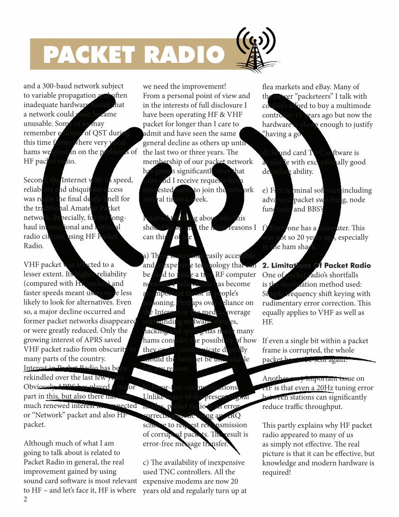
PACKET RADIO and a 300-baud network subject to variable propagation and often inadequate hardware meant that a network could soon became unusable. Some of us may remember editions of QST during this time frame where very vocal hams weighed in on the problems of HF packet radio.
Second, the Internet with its speed, reliability and ubiquitous access was really the final death-knell for the traditional Amateur Packet network. Especially, for the long-haul international and national radio circuits using HF Packet Radio.
VHF packet was affected to a lesser extent. Its higher reliability (compared with HF packet) and faster speeds meant users were less likely to look for alternatives. Even so, a major decline occurred and former packet networks disappeared or were greatly reduced. Only the growing interest of APRS saved VHF packet radio from obscurity in many parts of the country.Interest in Packet Radio has been rekindled over the last few years. Obviously APRS has played a major part in this, but also there has been much renewed interest in connected or “Network” packet and also HF packet.
Although much of what I am going to talk about is related to Packet Radio in general, the real improvement gained by using sound card software is most relevant to HF – and let’s face it, HF is where
we need the improvement!From a personal point of view and in the interests of full disclosure I have been operating HF & VHF packet for longer than I care to admit and have seen the same general decline as others up until the last two or three years. The membership of our packet network has grown significantly over that time and I receive requests from interested hams to join the network several times a week.
I started thinking about why this should be so, and the main reasons I can think of are :
a) There is no other easily accessible and inexpensive technology that can be used to make a true RF computer network. I believe this has become an important factor in people’s reasoning. Perhaps over reliance on the Internet or the media coverage surrounding malware, viruses, hacking and spying has made many hams consider the possibility of how they could communicate digitally should the Internet be unavailable for any reason.
b) Error-free communications. Unlike many of the present digital modes, packet radio is an error correcting mode using an ARQ scheme to request retransmission of corrupted packets. The result is error-free message transfer.
c) The availability of inexpensive used TNC controllers. All the expensive modems are now 20 years old and regularly turn up at
flea markets and eBay. Many of the newer “packeteers” I talk with couldn’t afford to buy a multimode controller 15 years ago but now the hardware is cheap enough to justify “having a go”
d) Sound card TNC software is available with exceptionally good decoding ability.
e) Free terminal software including advanced packet switching, node functions and BBS’s.
f) Everyone has a computer. This was not so 20 years ago, especially in the ham shack.
2. Limitations Of Packet RadioOne of packet radio’s shortfalls is the modulation method used: Simple frequency shift keying with rudimentary error correction. This equally applies to VHF as well as HF.
If even a single bit within a packet frame is corrupted, the whole packet has to be sent again.
Another very important issue on HF is that even a 20Hz tuning error between stations can significantly reduce traffic throughput.
This partly explains why HF packet radio appeared to many of us as simply not effective. The real picture is that it can be effective, but knowledge and modern hardware is required!

3
PACKET RADIOLet’s look at a typical packet radio “channel” on HF. (Shown below)This example is from Network 105 on the 20m band.
As you can hopefully see, we have a number of packets showing on the waterfall and if you look closely at the cursor marks you’ll see some of these stations are actually mistunedEven the stations which are better aligned are still off by 20Hz or so. This mistuning is most likely caused by the basic accuracy of the transceivers being used and the
TNC tone generators which can drift over time. Because it’s not easy to tell if you are mistuned many packet stations will continue like this for years. Throughput is affected on these stations and any stations using them as a node or digipeater. The further off tune these stations are, the more detrimental to the network as a whole. Unfortunately the filters on traditional TNC modems are not very effective if the signal is not aligned correctly on the Mark & Space tones. You can often witness this by hearing a
good strong station but getting no decode showing on the screen. Re-tuning your own station is not going to help either because there are multiple stations on frequency and compensating for one will adversely affect reception of another.
In the next part of this article we will explore how using your computer’s sound card can overcome many of the problems inherent with HF packet.
To the left, the diagram shows two badly tuned packets

4
WHAT’S NEW
Three-Into-One Will Go!West Mountain Radio is pleased to announce the availability of our COMport Splitter software which we’ve designed to maximize your RIGblaster digital mode operating fun! The COMport Splitter application was designed to allow a RIGblaster* to share its single COM port with up to three applications simultaneously.
How It WorksThe program will create two or three virtual COM ports (depending on your needs) and maps the functions of CAT, PTT and FST/CW on each port. In the example below the RIGblaster Advantage original COM port (COM 5) has been split so that CAT/CI-V is now on COM 6, PTT
(RTS) is on COM 7 and FSK/CW (DTR) is now on COM 8. This particular example makes it possible to operate Ham Radio Deluxe for logging while simultaneously having two distinct COM ports for PTT and FSK RTTY!
Not all software and combinations will require three COM ports – for instance operating FSK with N1MM and MMTTY will require only two ports. In this case instruct the software not to split CW/FSK. In another example you can split the RIGblaster Advantage’s original COM port (COM 5) so that CAT/CI-V is now on COM 6, PTT (RTS) and CW/FSK (DTR) is now on COM 7. MMTTY with ExtFSK106 utilizes a single COM port for both PTT & FSK.
Depending on which digital modes software you are using will determine how you initialize the COMport Splitter software. It’s inherent flexibility should mean that you have the tools to deal with any situation.
Requirements*The West Mountain Radio COMPort Splitter works with the RIGblaster Advantage, RIGblaster Plus-II, RIGblaster Duo and the RIGblaster Plug & Play. It runs on Windows XP, Vista, Windows 7 and Windows 8.
More InformationYou can download your copy from:http://www.westmountainradio.com/comport
COMport SplitterFor select RIGblasters

5
Michael MartinW9TSQ
In a mechanical sense, the antenna can be thought of like a metal ruler clamped to the edge of a table or like a tuning fork or wind chime. The ruler will vibrate at a mechanical resonant frequency much like a single element antenna on a grounded plate or ground plane. The tuning fork or wind chime is much like a ½ wave dipole antenna with the two resonant ends vibrating out of phase with each other, the center point being a null point relative to the active ends. The ¼ wave antenna acts much the same way as the metal ruler example above, but resonating at the effective electrical length of the antenna element.
You can envision the resonant element as having increasing impedance along the element from a low impedance at the ground referenced base to a high impedance at the tip. The electrical length along with the element’s composition and the capacitance of the surroundings are what ultimately determine the resonant frequency of the antenna. The composition and construction, meaning the antenna’s material, conductor size, resistance, and the ratio of total inductance to total capacitance, all take a part in
determining the achievable “Loaded Q” and the ultimate impedance and bandwidth of the antenna at resonance. Ideally, at resonance, the antenna’s inductive reactance and the capacitive reactance will be equal, leaving just the resistive losses.
At this point, the task at hand is to find the point on the antenna element where the element impedance matches the feedline impedance. Of course, like everything we deal with in the real world, there will be interaction between the antenna element’s self-resonant frequency, the feed point, the feedline and the antenna’s
surroundings. All of these will more often than not need to be tweaked with adjustments of the length of the antenna, the feed point, or even some additional capacitance in series with the feedline. When building and testing, keeping an accurate running record of the changes and results as they will provide help in getting things back to where things were working the best.
Grounding:Grounding of your antenna system and your entire station is job one. A good system reference point of ground radials or a ground counterpoise will make
ANTENNA SERIESThe AntennaPart 5 of Series
6
antenna measurements and the ultimate station performance more consistent and repeatable. There are the additional benefits of improved lightning and power surge protection of the station that will be the subject of another newsletter.
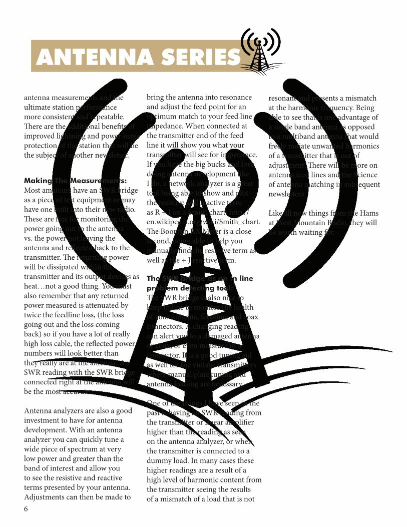
Making The Measurements:Most amateurs have an SWR bridge as a piece of test equipment or may have one built into their new radio. These are fine for monitoring the power going out to the antenna vs. the power not leaving the antenna and reflected back to the transmitter. The returning power will be dissipated within the transmitter and its output devices as heat…not a good thing. You must also remember that any returned power measured is attenuated by twice the feedline loss, (the loss going out and the loss coming back) so if you have a lot of really high loss cable, the reflected power numbers will look better than they really are at the antenna. An SWR reading with the SWR bridge connected right at the antenna will be the most accurate.
Antenna analyzers are also a good investment to have for antenna development. With an antenna analyzer you can quickly tune a wide piece of spectrum at very low power and greater than the band of interest and allow you to see the resistive and reactive terms presented by your antenna. Adjustments can then be made to
bring the antenna into resonance and adjust the feed point for an optimum match to your feed line impedance. When connected at the transmitter end of the feed line it will show you what your transmitter will see for impedance. If you have the big bucks and love doing antenna development like I do, a network analyzer is a great tool being able to show and plot the resistive and reactive term as R + J on a Smith chart. http://en.wikipedia.org/wiki/Smith_chart. The Boonton RX Meter is a close second, being able to help you manually find the resistive term as well as the + J reactive term.
The SWR bridge as an in line problem detecting tool:The SWR bridge is also nice to keep in line to monitor the health of your antenna, feedline, and coax connectors. A changing reading can alert you to a damaged antenna or coax, or even moisture in a connector. It is a good tuning aid as well for the vintage transmitters where manual plate tuning and antenna loading are necessary.
One of the things I have seen in the past is having an SWR reading from the transmitter or linear amplifier higher than the reading as seen on the antenna analyzer, or when the transmitter is connected to a dummy load. In many cases these higher readings are a result of a high level of harmonic content from the transmitter seeing the results of a mismatch of a load that is not
resonant and presents a mismatch at the harmonic frequency. Being able to see that is one advantage of a single band antenna as opposed to a multiband antenna that would freely radiate unwanted harmonics of a transmitter that is out of adjustment. There will be more on antenna feed lines and the Science of antenna matching in subsequent newsletters.
Like all new things from the Hams at West Mountain Radio, they will be worth waiting for.
ANTENNA SERIES

7
Developing Software Based 2G+ Automatic Link Establishment (ALE) Systems using the PC Sound Device as the Modem
Steve HajducekN2CKH
Background:A personal computer (PC) software based ALE modem/controller is a software application which utilizes a PC Sound Device Modem (PCSDM) as the modem hardware and PC serial port for remote control of an HF SSB transceiver to bring about an HF ALE system with a specific set of features which do not require a Hardware ALE modem/controller solution. Herein I shall provide insight into both MARS-ALE and PC-ALE as to their positions as 2G+ ALE Systems and their continuing development and the directions that their development life cycle are taking. PC-ALE on which MARS-ALE was originally based and which was originally developed by Charles Brain, G4GUO has stood the test of time and even MARS-ALE has now hit the 10 year mark having debuted in 2003. My main focus regarding Automatic Link Establishment (ALE) software development is in support of the U.S. Military Auxiliary Radio System (MARS) and other users of the MARS-ALE
toolset. However PC-ALE which mostly serves the Amateur Radio Service (ARS) user base comes next and many features are developed for PC-ALE that are Amateur Radio specific and not just migrated from the MARS-ALE baseline. The MARS-ALE and PC-ALE software serve different user bases and purposes and thus have modems that are tailored differently and also different sets of operational features but yet share many common features as well. The SWL Utility monitor segment makes use of both of PC-ALE and MARS-ALE, however MARS-ALE has more features suited to such applications.
ALE Generations:The standards for Second Generation (2G) ALE has been around for a while now, even 3G ALE has 10 years on it with Military users at this point, although its somewhat limited in use still. The Military, Government, Commercial and Humanitarian users of ALE mostly all make use of dedicated hardware based ALE transceivers at this point. There are a few exceptions where
dedicated external 2G and even 3G ALE modem/controllers that are either firmware or RTOS software based are available for use with a supported standard HF SSB transceiver. Furthermore, most all Commercial and surplus Military hardware HF-ALE gear available to Amateur Radio, MARS and various other volunteer budget priced purchasers are strictly 2G ALE based. Although many Radio Amateurs and MARS members do have hardware ALE, the bulk of users take the General Purpose PC and Software based ALE modem/controller system route using a standard HF SSB transceiver do to cost.
The main differences between 2G and 3G ALE is that 2G ALE is AFSK based using 8 discrete tones modulated at a 125 baud symbol rate and where 3G ALE is PSK serial tone based modulated at a 2400 baud symbol rate. In addition 2G ALE is Asynchronous operating within a set framework of rules to achieve timing where Sounding transmissions and Linking calls have specified durations utilized to bring about intercept and decoding whereas
MARS-ALE
Part 1 of the Series

8
3G ALE is Synchronous based on precise Global Positioning Satellite (GPS) and other time standard source reference in multi-channel operation without the need for Sounding transmissions and lengthy calls to achieve decoding as stations are on a given frequency when they should be based on precise time slots. Here in the U.S. at this time, the prospect of 3G ALE use via Amateur Radio is hampered by both the rules governing symbol rate and the 3G technical limitation on unique ID which precludes the use of standard Amateur Radio call signs. In MARS the rules do not get in the way, however the limitation is the availability of 3G ALE systems due to cost, which will need to be addressed by 3G ALE software at some point.
Software ALE vs. Hardware ALE:MARS-ALE and PC-ALE are software based “ALE systems”. The difference between an ALE system vs. ALE transceiver is that with an ALE system the ALE modem/controller is external to the HF SSB transceiver and that transceiver can either be designed to work with the external ALE modem/controller from the same manufacturer as the radio or it can be a more generic external ALE modem controller from a 3rd party that decides to support certain make/models of HF SSB transceivers. Although the ALE system controller must know how
to remote control the transceiver for multi-channel ALE operation, there are usually no provisions in 3rd party external ALE controllers to hold any use of manual relays out in bypass when used in the transceivers RF power amplifier spectral purity filter selection as is done when the ALE controller is from the same manufacturer as the transceiver and as provided by MARS-ALE and PC-ALE when radio provides such remote control means. Many early Commercial and Military hardware ALE offerings were ALE systems where the Military ones utilized transceivers and external mcontrollers designed to work together and the Commercial ones were more generic as to the transceivers supported. A recently developed hardware ALE system by RapidM, their RT5 Tactical Terminal, is a 3G ALE system that utilizes a dedicated Linux OS which is all software based and supports various commercial HF SSB transceivers that were not designed for ALE or were designed for ALE when an ALE option is installed internally.
ALE Adoption:The use of 2G ALE is the world standard for ALE and has come into common use within the Amateur Radio Service world wide. To a large extent this has been driven within the ARS by the use of the PC Sound Device as the modem, which means PC-ALE in particular as it was the first Sound
Device ALE application available and still leads the pack. However there are an awful lot of hardware ALE users within the Amateur Radio ranks and MARS as well, where Commercial and Military surplus hardware ALE systems and ALE transceivers are being utilized, which cannot easily or inexpensively be augmented with new features via field firmware update or at all, which continues to keep 2G ALE in wide use. Here in the U.S. the use of ALE within MARS began with all hardware ALE but with a small number of MARS members so equipped and then increased with the use of PC-ALE being permitted and then exploded with the creation of MARS-ALE which was tailored for MARS needs. As compact Military ALE transceivers came about due to advances in Digital Signal Processors (DSP) availability, the MIL-STD for ALE evolved as well and Alternate Quick Call-ALE (AQC-ALE) came about and found its way into Military ALE Manpack Portable and other Military Tactical ALE and Military Airborne ALE transceivers. AQC-ALE was represented a major improvement to AFSK ALE but has never been widely used as it has not found its way into commercial ALE transceivers and even in the Military due to the large installed based of ALE, has been relegated to Special Operation Forces Tactical use, although AQC-ALE is found in both MARS-ALE and PC-ALE. Although still an AFSK based
MARS-ALE

9
Asynchronous ALE and Amateur Radio legal, AQC-ALE was a streamlined ALE with much faster (2 and 5 ch/sec scan rates only) and much more robust Sounding, Calling and Linking due to a combination of shorting aspects of the ALE protocol parameters to included the ALE Self ID which was shortened from a maximum of 15 characters to 6 characters maximum. In most all Military use of ALE or AQC-ALE the use of 3 characters is routinely used and no more than 6 characters are used, as it has been determined that shorted is better under poor channel conditions. The use of 15 characters for ALE came about by some one desiring to support up to 15 character Automatic Digital Network System (AUTODIN)phone numbers as ALE ID’s, rather foolish in my opinion. These days the ALE AMD message protocol using the HF Ground Routing Protocol specified in ACP-193(A) is utilized to automate phone patch access and other remote signaling where ALE Link Protection is used as required. AQC-ALE can be thought of as 2.5G ALE in that it is much more advanced than ALE, having such additional tactical features of “Meet Me” which allows automatically steering a Network of users to another channel by a single Net Control Station transmission and having “Dictionary” Messaging where messages are created from tokenized associated lists the users have pre-configured and in
common for AMD messaging. AQC-ALE however is not found in non-Military ALE transceivers.
ALE and Data Modems:In addition to AQC-ALE, the Military grade ALE transceivers started to add MIL-STD and later STANAG high speed PSK Data Modem capability for ALE follow on communications as an internal capability rather than have the need to lug around an external data modem and data terminal, which gave way to ruggedized laptops and tactical chat application software. MARS-ALE provides for MIL-STD-188-110A (MS110A) data modem for ASYNC RATT and FED-STD-1052 Appendix B Data Link Protocol (DLP) for Broadcast and ARQ support as part of the standard features supported on the PC Sound Device. PC-ALE also provides FS-1052 support, however due to FCC rules in the U.S., this use of PC-ALE is very limited due to the 2400 baud symbol rate of the MS110A data modem. There are no such limitations
on MARS use and as MARS has now embraced MIL-STD data modem use, the MS110A modem in MARS-ALE has been improved by the addition of new MS110A modem code developed for the MIL-STD Data Modem Terminal (MS-DMT) software specifically developed for MARS. Also use of the MS110A in MARS-ALE has been enhanced to support more than FS-1052 DLP use, which itself is being enhanced with the addition of CIRCUIT mode to the existing 1052 ARQ and BROADCAST modes. In addition,
MARS-ALE

10
additional MIL-STD and STANAG data modems and DLP standards are planned for inclusion in MARS-ALE utilizing the PC Sound Device. It is also planned for MARS-ALE to optionally support external hardware MIL-STD data modems with its DLP support and to provide an external Data Port similar to what MS-DMT provides in support of external Data Terminal applications use of the data modem in MARS-ALE.
ALE link protection:Another aspect of ALE and AQC-ALE that Military ALE transceivers provide is Link Protection (LP), something that is also not found in Commercial ALE transceivers but which is being developed MARS-ALE in support of MARS use. Link Protection causes the ALE words to be scrambled, thus providing protection that prevents ALE users which do not have the current LP key in use from entering a given LP network and thus preventing them from linking to spoof or monitoring transmissions. Link Protection is employed just below the ALE protocol within the data link layer. A principal consideration in implementing LP is that of transparency in the presence of an LP in that it shall have no impact on any protocols outside of the protection sub layer in the ALE data link layer. In particular, this means that achieving and maintaining LP sync must occur transparently to the ALE waveform and protocols, and that scanning radios must be able to acquire LP sync at any
cryptography where perhaps LP ALE may become usable in support of ARS ECOM support where MARS-LP-ALE could be provided to organizations such as ARRL ARES for their use. There are no such issues regarding the use of LP in MARS, where LP may become critical to the use of ALE in the MARS customer support mission, as such MARS-LP-ALE is being developed to provide AL-1 and AL-2 Link Protection with GPS and other Internet Time Server support and the ability of a station to act as a Timer Server over the air in support of other MARS-LP-ALE stations. What goes out the window with MARS-LP-ALE due to timing issues associated with maintaining LP sync is the software overhead involved in the Split VFO approach to addressing PA filter section relays used to select spectral purity filters which in MARS-ALE and PC-ALE is referred to as Quiet Scanning/Sounding (QS/S) that keeps those pesky relays in bypass during multi- channel ALE scanning. Thus any radio used with MARS-LP-ALE must use PIN diodes instead of relays or must be directly controllable for bypass via a single remote control command or be hardware modified using methods such as have been developed for the popular ICOM IC-718 and IC-7200 and other radios. Stay tuned for the next in the Series....
point in the scanning call portion of a protected transmission if this transmission was scrambled under the key in use by the receiving station. Link Protection includes time of day (TOD) and frequency inputs to counter playback attack, thus identical plaintext ALE words encrypted under the same key that were recorded and being played back will produce different results at different times of day or on different frequencies. In addition there are different levels of Link Protection where Level 0 (AL-0) is normal ALE without any Link Protection and Level 1 (AL-1) and Level 2 (AL-2) provide protection by the introduction of their scrambling algorithms and levels of precise time accuracy where AL-1 uses a protection interval of 60 seconds and AL-2 has a protection interval of 2 seconds accuracy.
The AL-1 and AL-2 algorithm are published, beyond AL-2 the next two levels of algorithms are NSA classified, as AL-1 and AL-2 are mandatory of any LP equipped HF-ALE transceiver, there is a level of inter operability between MARS and any customer requiring LP support. As it is the strength of the algorithm and the size of its key that allows LP to stand up to the aspect of cryptographic attack, this is why beyond AL-2 the algorithms are classified. At present there are issues with the use of cryptography under FCC rules, I don’t know about Amateur Radio rules elsewhere, however the FCC is currently reviewing the use of
MARS-ALE

11
If you would like to submit an article for consideration in future newsletters please contact
West Mountain Radio 1020 Spring City Dr. Waukesha, WI 53186
www.westmountainradio.com
Visit us on these social networks:
Get what you REALLY want for the
Holidays!
Create a wishlist now at
and share it with your loved ones
westmountainradio.com
HAMFESTS
UPCOMING EVENTS
Customer Comments“The support you give must be some of the best in the business.”
“I will recommend the RIGblaster Advantage to future HAMS who need a seamless solution for digital modes.”
“Thanks so much for the speedy repair of the CLRdsp processor. It makes a really big difference in removing noise and rendering speech easier to copy.”
January
“Thank you so very much. I guarantee I will be telling everyone I know and meet about your product and service.”
“I’ve ordered a third RIGrunner setup, I find them very handy!”
1/04/2014 *41st Annual Midwinter Swapfest Waukesha, WI
February2/7/2014 *Orlando Hamcation®
Orlando, FL
*West Mountain Radio will be attending
When you talk...we listen!Make suggestions or comments on proposed new products.
www.westmountainradio.com/insiders
Become an “Insider” today