THE BASIC STARTER KIT TUTORIAL FOR UNO
83
THE BASIC STARTER KIT TUTORIAL FOR UNO V1.0.17.7.9
Transcript of THE BASIC STARTER KIT TUTORIAL FOR UNO

THE BASIC STARTER KIT TUTORIAL
FOR UNO
V1.0.17.7.9

2 / 83
Our Company
Preface
Established in 2011, Elegoo Inc. is a thriving technology company dedicated to open-
source hardware research & development, production and marketing. Located in
Shenzhen, the Silicon Valley of China, we have grown to over 150+ employees with
a 10,763+ square ft. factory.
Our product lines rang from DuPont wires, UNO R3 boards to complete starter kits
designed for customers of any level to learn Arduino knowledge. In addition, we also
sell products of Raspberry Pi accessories like 2.8’’ TFT touch and STM32. In the
future we would devote more energy and investment to 3D printer products and so
on. All of our products comply with international quality standards and are greatly
appreciated in a variety of different markets throughout the world.
Official website: http://www.elegoo.com
US Amazon storefront: http://www.amazon.com/shops/A2WWHQ25ENKVJ1
CA Amazon storefront: http://www.amazon.ca/shops/A2WWHQ25ENKVJ1
UK Amazon storefront: http://www.amazon.co.uk/shops/A1780XYQ9DFQM6
DE Amazon storefront: http://www.amazon.de/shops/A1780XYQ9DFQM6
FR Amazon storefront: http://www.amazon.de/shops/A1780XYQ9DFQM6
ES Amazon storefront: http://www.amazon.de/shops/A1780XYQ9DFQM6
IT Amazon storefront: http://www.amazon.de/shops/A1780XYQ9DFQM6
Our Tutorial
This tutorial is designed for beginners. You will learn all the basic information about
how to use Arduino controller board, sensors and components. If you want to study
Arduino in more depth, we recommend that you read the Arduino Cookbook written
by Michael Margolis.
Some codes in this tutorial is edited by Simon Monk. Simon Monk is author of a
number of books relating to Open Source Hardware. They are available in Amazon:
Programming Arduino, 30 Arduino Projects for the Evil Genius and Programming the
Raspberry Pi.
Customer Service
As a continuous and fast growing technology company we keep striving our best to

3 / 83
offer you excellent products and quality service as to meet your expectation and you
can reach out to us by simply drop a line at [email protected] or
[email protected]. We look forward to hearing from you and any of your critical
comment or suggestion would be much valuable to us.
And any of problems and questions you have with our products will be promptly
replied by our experienced engineers within 12 hours (24hrs during holiday)
4 / 83

5 / 83
Content
Lesson 0 Installing IDE ............................................................................................................... 6
Lesson 1 Add Libraries and Open Serial Monitor ................................................................... 17
Lesson 2 Blink ........................................................................................................................... 26
Lesson 3 LED ............................................................................................................................. 37
Lesson 4 RGB LED ..................................................................................................................... 44
Lesson 5 Digital Inputs ............................................................................................................. 53
Lesson 6 Active buzzer ............................................................................................................. 58
Lesson 7 Tilt Ball Switch ........................................................................................................... 62
Lesson 8 Eight LED with 74HC595 ............................................................................................ 66
Lesson 9 The Serial Monitor .................................................................................................... 73
Lesson 10 Photocell ................................................................................................................. 79

6 / 83
Lesson 0 Installing IDE
Introduction
The Arduino Integrated Development Environment (IDE) is the software side of the
Arduino platform.
In this lesson, you will learn how to setup your computer to use Arduino and how
to set about the lessons that follow.
The Arduino software that you will use to program your Arduino is available for
Windows, Mac and Linux. The installation process is different for all three platforms
and unfortunately there is a certain amount of manual work to install the software.
STEP 1: Go to https://www.arduino.cc/en/Main/Software and find below page.
The version available at this website is usually the latest version, and the actual
version may be newer than the version in the picture.
7 / 83
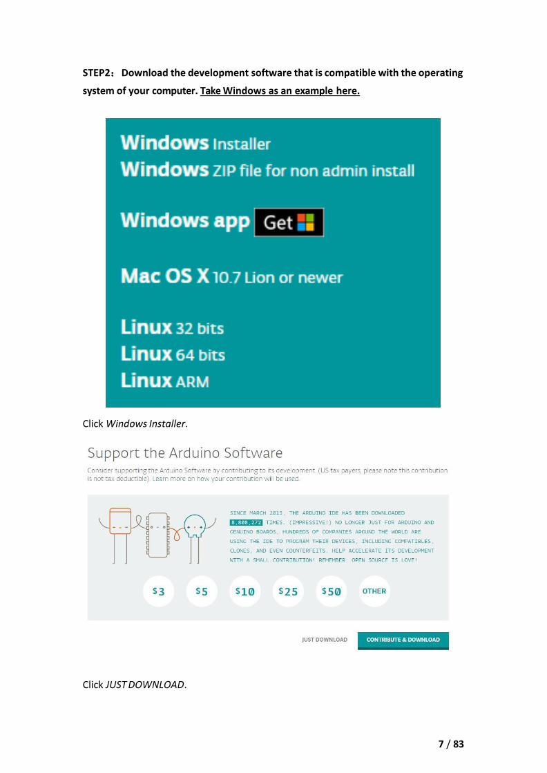
STEP2:Download the development software that is compatible with the operating
system of your computer. Take Windows as an example here.
Click Windows Installer.
Click JUST DOWNLOAD.
8 / 83
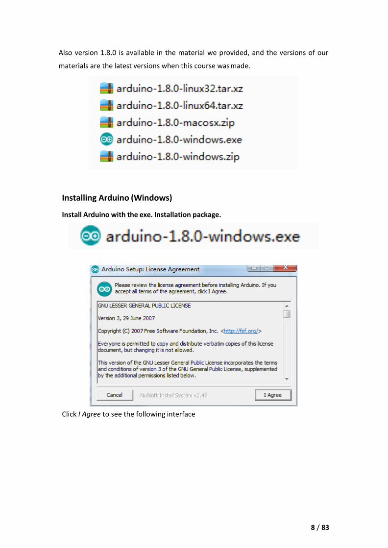
Also version 1.8.0 is available in the material we provided, and the versions of our
materials are the latest versions when this course was made.
Installing Arduino (Windows)
Install Arduino with the exe. Installation package.
Click I Agree to see the following interface
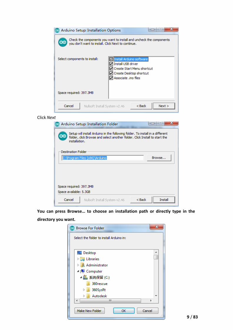
Click Next
You can press Browse… to choose an installation path or directly type in the
directory you want.
9 / 83
10 / 83
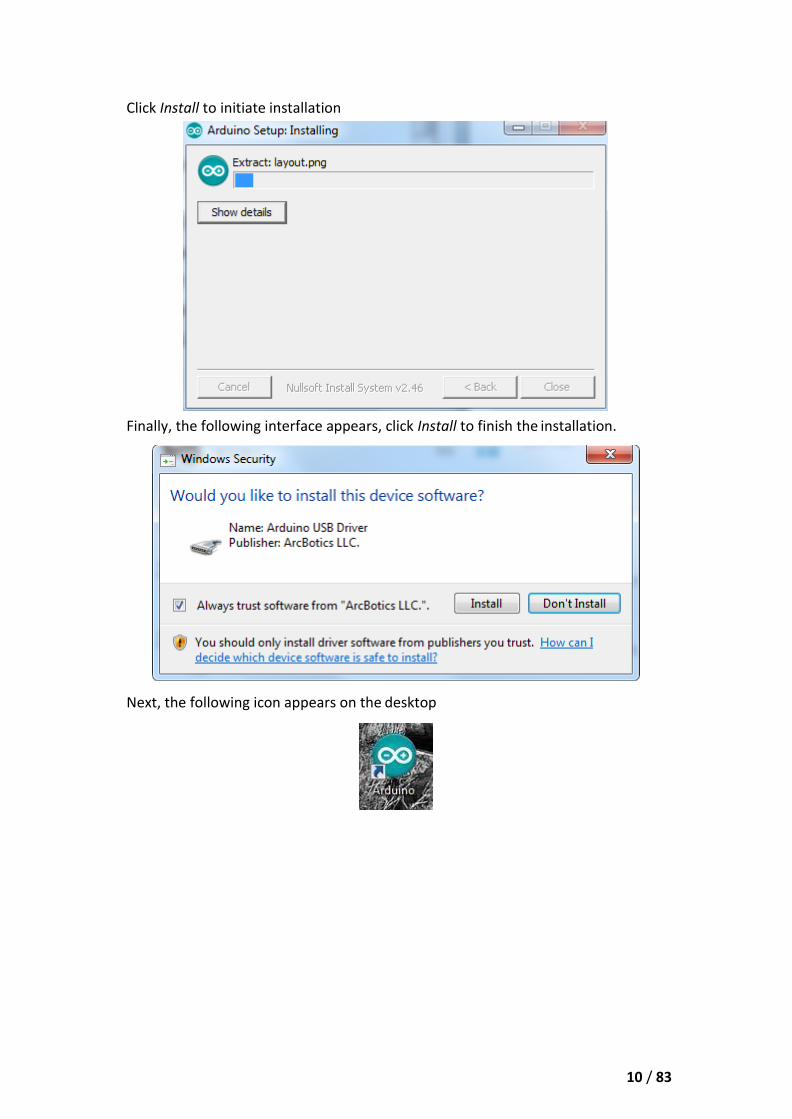
Click Install to initiate installation
Finally, the following interface appears, click Install to finish the installation.
Next, the following icon appears on the desktop

11 / 83
Double-click to enter the desired development environment
You may directly choose the installation package for installation and skip the
contents below and jump to the next section. But if you want to learn some methods
other than the installation package, please continue to read the section.
Unzip the zip file downloaded, Double-click to open the program and enter the
desired development environment

12 / 83

13 / 83
However, this installation method needs separate installation of driver.
The Arduino folder contains both the Arduino program itself and the drivers that
allow the Arduino to be connected to your computer by a USB cable. Before we
launch the Arduino software, you are going to install the USB drivers.
Plug one end of your USB cable into the Arduino and the other into a USB socket on
your computer. The power light on the LED will light up and you may get a 'Found
New Hardware' message from Windows. Ignore this message and cancel any
attempts that Windows makes to try and install drivers automatically for you.
The most reliable method of installing the USB drivers is to use the Device Manager.
This is accessed in different ways depending on your version of Windows. In
Windows 7, you first have to open the Control Panel, then select the option to view
Icons, and you should find the Device Manager in the list.
Under ‘Other Devices’, you should see an icon for ‘unknown device’ with a little
yellow warning triangle next to it. This is your Arduino.
14 / 83
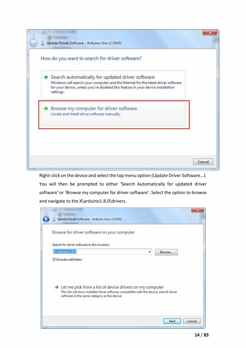
Right-click on the device and select the top menu option (Update Driver Software...).
You will then be prompted to either ‘Search Automatically for updated driver
software’ or ‘Browse my computer for driver software’. Select the option to browse
and navigate to the X\arduino1.8.0\drivers.

15 / 83
Click 'Next' and you may get a security warning, if so, allow the software to be
installed. Once the software has been installed, you will get a confirmation message.
Windows users may skip the installation directions for Mac and Linux systems and
jump to Lesson 1. Mac and Linux users may continue to read this section.
Installing Arduino (Mac OS X)
Download and Unzip the zip file, double click the Arduino.app to enter Arduino IDE;
the system will ask you to install Java runtime library if you don’t have it in your
computer. Once the installation is complete you can run the Arduino IDE.

16 / 83
Installing Arduino (Linux)
You will have to use the make install command. If you are using the Ubuntu system, it is
recommended to install Arduino IDE from the software center of Ubuntu.
TIPS: If you have problems in installing the drivers, please refer to the UNO R3,
MEGA, NANO DRIVER FAQ.

17 / 83
Lesson 1 Add Libraries and Open Serial Monitor
Installing Additional Arduino Libraries
Once you are comfortable with the Arduino software and using the built-in functions,
you may want to extend the ability of your Arduino with additional libraries.
What are Libraries?
Libraries are a collection of code that makes it easy for you to connect to a sensor,
display, module, etc. For example, the built-in LiquidCrystal library makes it easy to
talk to character LCD displays. There are hundreds of additional libraries available
on the Internet for download. The built-in libraries and some of these additional
libraries are listed in the reference. To use the additional libraries, you will need to
install them.
How to Install a Library
Using the Library Manager
To install a new library into your Arduino IDE you can use the Library Manager
(available from IDE version 1.8.0). Open the IDE and click to the "Sketch" menu and
then Include Library > Manage Libraries.
18 / 83
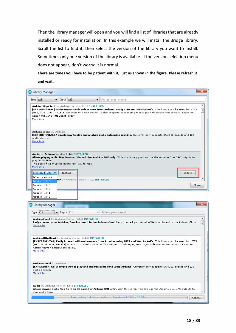
Then the library manager will open and you will find a list of libraries that are already
installed or ready for installation. In this example we will install the Bridge library.
Scroll the list to find it, then select the version of the library you want to install.
Sometimes only one version of the library is available. If the version selection menu
does not appear, don't worry: it is normal.
There are times you have to be patient with it, just as shown in the figure. Please refresh it
and wait.
19 / 83
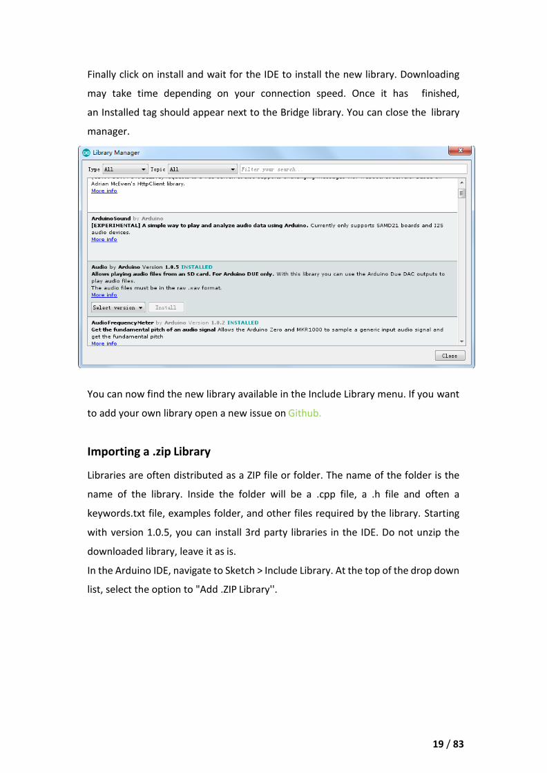
Finally click on install and wait for the IDE to install the new library. Downloading
may take time depending on your connection speed. Once it has finished,
an Installed tag should appear next to the Bridge library. You can close the library
manager.
You can now find the new library available in the Include Library menu. If you want
to add your own library open a new issue on Github.
Importing a .zip Library
Libraries are often distributed as a ZIP file or folder. The name of the folder is the
name of the library. Inside the folder will be a .cpp file, a .h file and often a
keywords.txt file, examples folder, and other files required by the library. Starting
with version 1.0.5, you can install 3rd party libraries in the IDE. Do not unzip the
downloaded library, leave it as is.
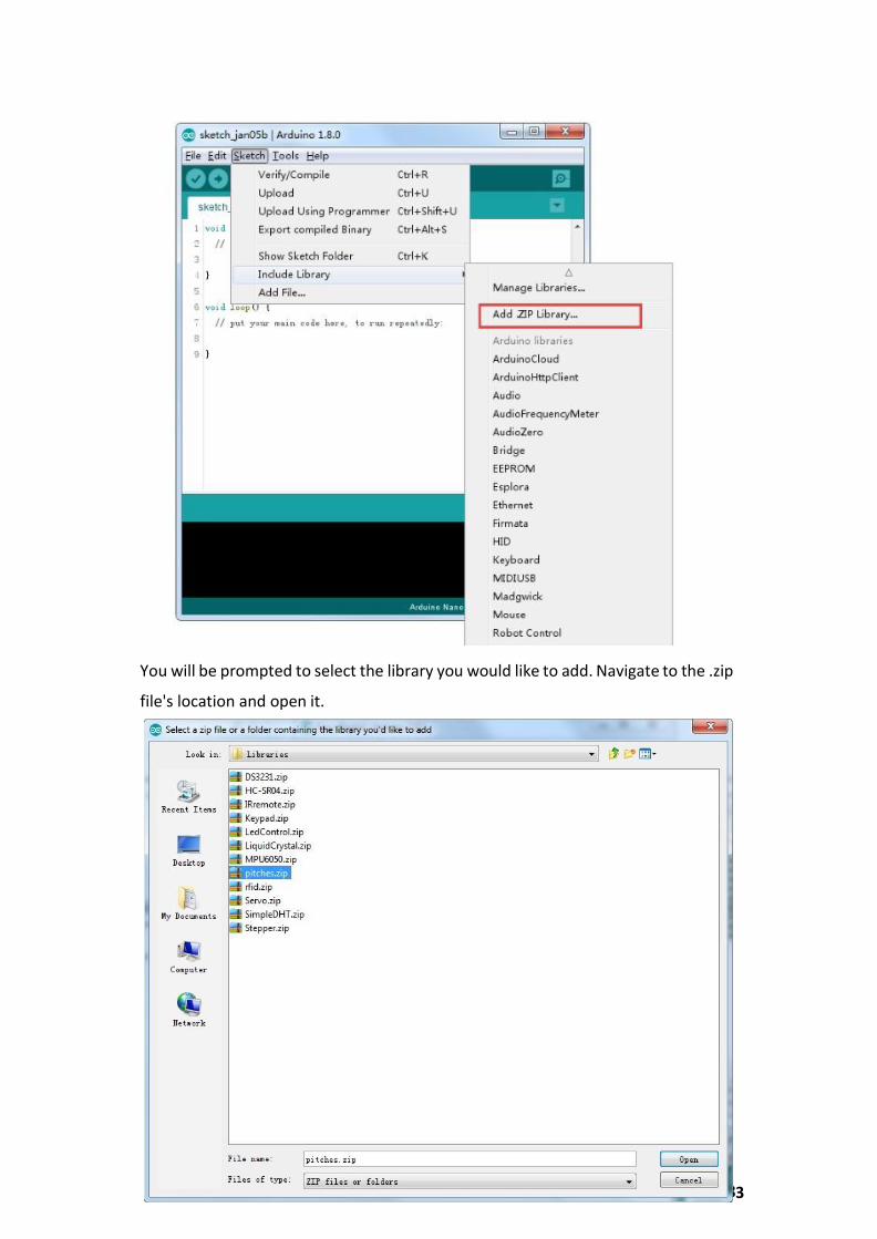
In the Arduino IDE, navigate to Sketch > Include Library. At the top of the drop down
list, select the option to "Add .ZIP Library''.
3
20 / 8
You will be prompted to select the library you would like to add. Navigate to the .zip
file's location and open it.

21 / 83
Return to the Sketch > Import Library menu. You should now see the library at the
bottom of the drop-down menu. It is ready to be used in your sketch. The zip file
will have been expanded in the libraries folder in your Arduino sketches directory.
NB: the Library will be available to use in sketches, but examples for the library will
not be exposed in the File > Examples until after the IDE has restarted.
Those two are the most common approaches. MAC and Linux systems can be
handled likewise. The manual installation to be introduced below as an alternative
may be seldom used and users with no needs may skip it.
Manual installation
To install the library, first quit the Arduino application. Then uncompress the ZIP file
containing the library. For example, if you're installing a library called

22 / 83
"ArduinoParty", uncompress ArduinoParty.zip. It should contain a folder
calledArduinoParty, with files like ArduinoParty.cpp and ArduinoParty.h inside. (If
the .cpp and .h files aren't in a folder, you'll need to create one. In this case, you'd
make a folder called "ArduinoParty" and move into it all the files that were in the
ZIP file, like ArduinoParty.cpp and ArduinoParty.h.)
Drag the ArduinoParty folder into this folder (your libraries folder). Under Windows,
it will likely be called "My Documents\Arduino\libraries". For Mac users, it will likely
be called "Documents/Arduino/libraries". On Linux, it will be the "libraries" folder
in your sketchbook.
Your Arduino library folder should now look like this (on Windows):
My Documents\Arduino\libraries\ArduinoParty\ArduinoParty.cpp
My Documents\Arduino\libraries\ArduinoParty\ArduinoParty.h
My Documents\Arduino\libraries\ArduinoParty\examples
or like this (on Mac and Linux):
Documents/Arduino/libraries/ArduinoParty/ArduinoParty.cpp
Documents/Arduino/libraries/ArduinoParty/ArduinoParty.h
Documents/Arduino/libraries/ArduinoParty/examples
....
There may be more files than just the .cpp and .h files, just make sure they're all
there. (The library won't work if you put the .cpp and .h files directly into the
libraries folder or if they're nested in an extra folder. For example:
Documents\Arduino\libraries\ArduinoParty.cpp and
Documents\Arduino\libraries\ArduinoParty\ArduinoParty\ArduinoParty.cpp won't
work.)
Restart the Arduino application. Make sure the new library appears in the Sketch-
>Import Library menu item of the software. That's it! You've installed a library!
Arduino Serial Monitor (Windows, Mac, Linux)
The Arduino Integrated Development Environment (IDE) is the software side of the
Arduino platform. And, because using a terminal is such a big part of working with
23 / 83
Arduinos and other microcontrollers, they decided to include a serial terminal with
the software. Within the Arduino environment, this is called the Serial Monitor.
Making a Connection
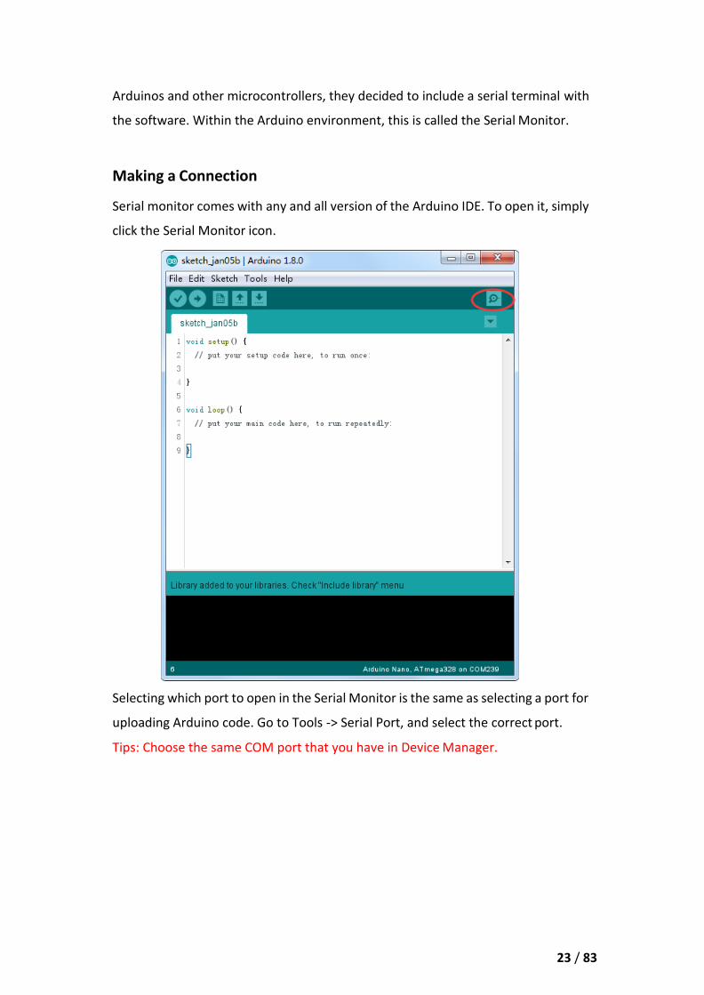
Serial monitor comes with any and all version of the Arduino IDE. To open it, simply
click the Serial Monitor icon.
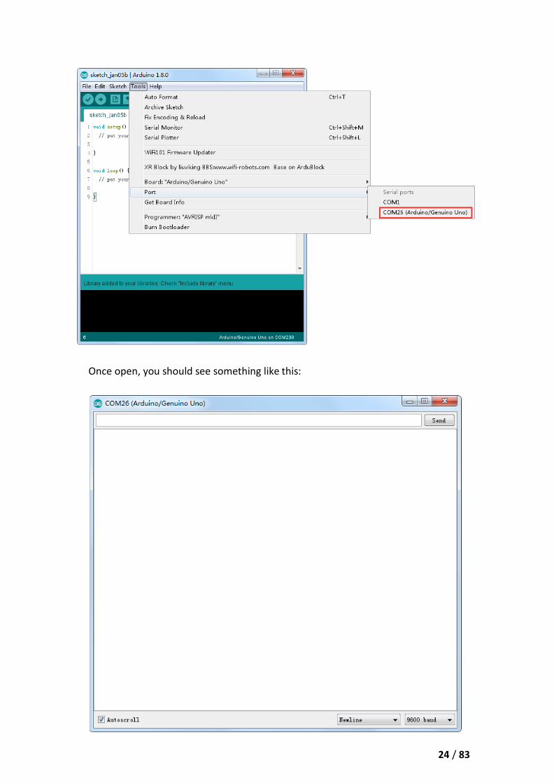
Selecting which port to open in the Serial Monitor is the same as selecting a port for
uploading Arduino code. Go to Tools -> Serial Port, and select the correct port.
Tips: Choose the same COM port that you have in Device Manager.
24 / 83
Once open, you should see something like this:

25 / 83
Settings
The Serial Monitor has limited settings, but enough to handle most of your serial
communication needs. The first setting you can alter is the baud rate. Click on the
baud rate drop-down menu to select the correct baud rate. (9600 baud)
Last, you can set the terminal to Autoscroll or not by checking the box in the bottom
left corner.
Pros
The Serial Monitor is a great quick and easy way to establish a serial connection with
your Arduino. If you’re already working in the Arduino IDE, there’s really no need to
open up a separate terminal to display data.
Cons
The lack of settings leaves much to be desired in the Serial Monitor, and, for
advanced serial communications, it may not do the trick.

26 / 83
Lesson 2 Blink
Overview
In this lesson, you will learn how to program your UNO R3 controller board to blink
the Arduino’s built-in LED, and how to download programs by basic steps.
Component Required:
(1) x Elegoo Uno R3
Principle
The UNO R3 board has rows of connectors along both sides that are used to connect
to several electronic devices and plug-in 'shields' that extends its capability.
It also has a single LED that you can control from your sketches. This LED is built
onto the UNO R3 board and is often referred to as the 'L' LED as this is how it is
labeled on the board.
27 / 83
You may find that your UNO R3 board's 'L' LED already blinks when you connect it
to a USB plug. This is because the boards are generally shipped with the 'Blink'
sketch pre-installed.
In this lesson, we will reprogram the UNO R3 board with our own Blink sketch and
then change the rate at which it blinks.
In Lesson 0, you set up your Arduino IDE and made sure that you could find the right
serial port for it to connect to your UNO R3 board. The time has now come to put
that connection to the test and program your UNO R3 board.
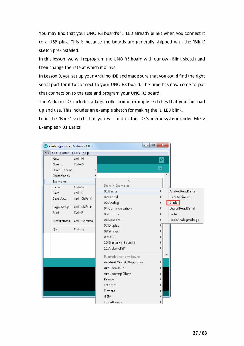
The Arduino IDE includes a large collection of example sketches that you can load
up and use. This includes an example sketch for making the 'L' LED blink.
Load the 'Blink' sketch that you will find in the IDE's menu system under File >
Examples > 01.Basics

28 / 83
When the sketch window opens, enlarge it so that you can see the entire sketch in
the window.
The example sketches included with the Arduino IDE are 'read-only'. That is, you can
upload them to an UNO R3 board, but if you change them, you cannot save them as
the same file.
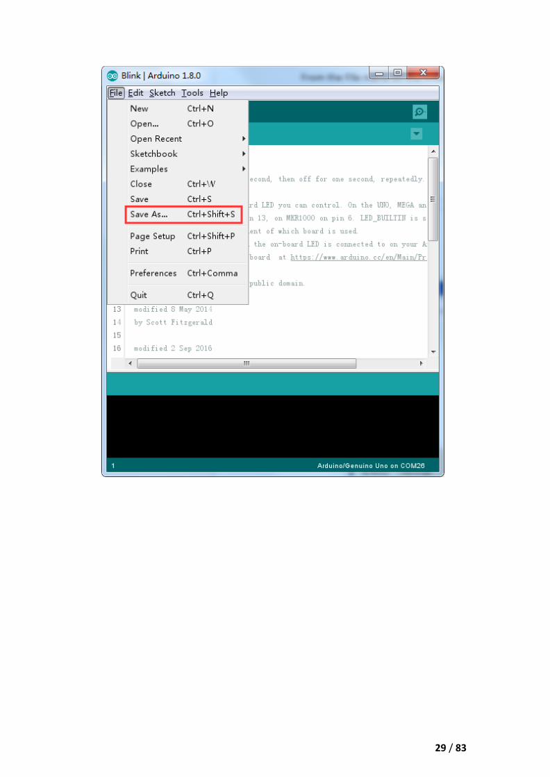
Since we are going to change this sketch, the first thing you need to do is save your
own copy.
From the File menu on the Arduino IDE, select 'Save As..' and then save the sketch
with the name 'MyBlink'.
29 / 83

30 / 83
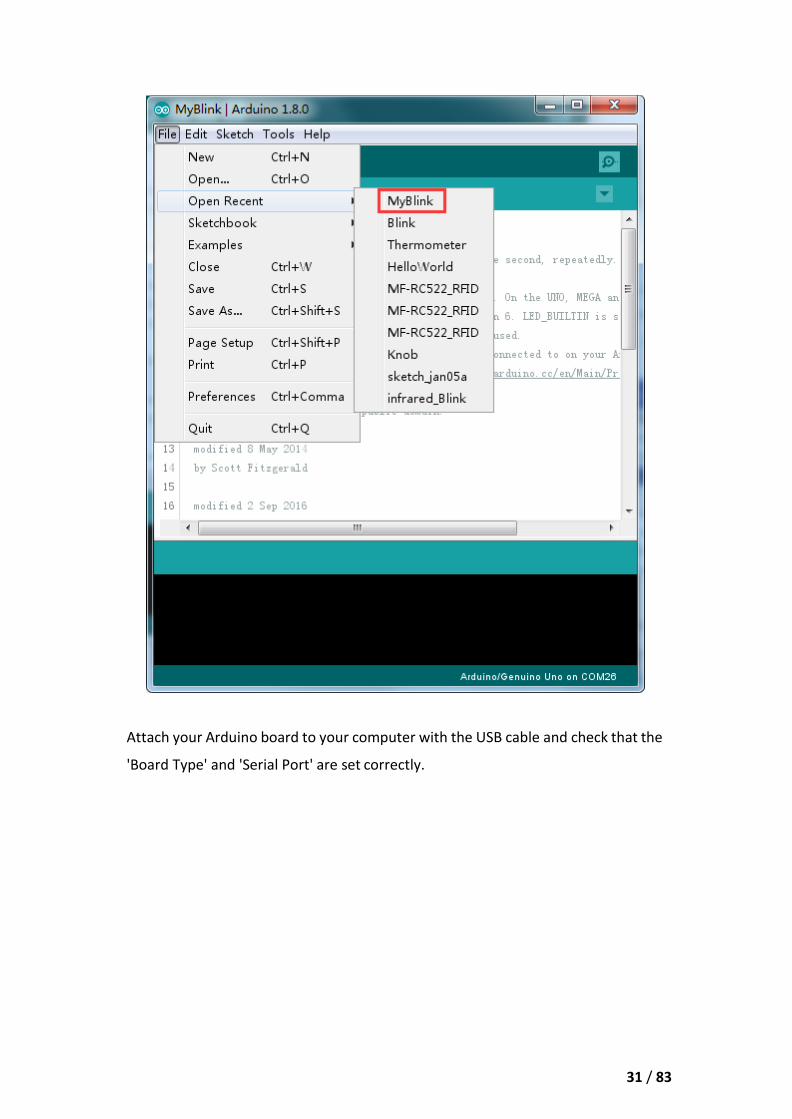
You have saved your copy of 'Blink' in your sketchbook. This means that if you ever
want to find it again, you can just open it using the File > Sketchbook menu option.
31 / 83
Attach your Arduino board to your computer with the USB cable and check that the
'Board Type' and 'Serial Port' are set correctly.

32 / 83

33 / 83
Note: The Board Type and Serial Port here are not necessarily the same as shown
in picture. If you are using 2560, then you will have to choose Mega 2560 as the
Board Type, other choices can be made in the same manner. And the Serial Port
displayed for everyone is different, despite COM 26 chosen here, it could be COM3
or COM4 on your computer. A right COM port is supposed to be COMX (arduino
XXX), which is by the certification criteria.
The Arduino IDE will show you the current settings for board at the bottom of the
window.
Click on the 'Upload' button. The second button from the left on the toolbar.
If you watch the status area of the IDE, you will see a progress bar and a series of
messages. At first, it will say 'Compiling Sketch...'. This converts the sketch into a
format suitable for uploading to the board.
Next, the status will change to 'Uploading'. At this point, the LEDs on the Arduino
should start to flicker as the sketch is transferred.

34 / 83
Finally, the staus will change to 'Done'.
The other message tells us that the sketch is using 928 bytes of the 32,256 bytes
available.After the 'Compiling Sketch..' stage you could get the following error
message:
It can mean that your board is not connected at all, or the drivers have not been
installed (if necessary) or that the wrong serial port is selected.
If you encounter this, go back to Lesson 0 and check your installation.
Once the upload has completed, the board should restart and start blinking.
Open the code
Note that a huge part of this sketch is composed of comments. These are not actual
program instructions; rather, they just explain how the program works. They are
there for your benefit.
Everything between /* and */ at the top of the sketch is a block comment; it explains
what the sketch is for.
35 / 83
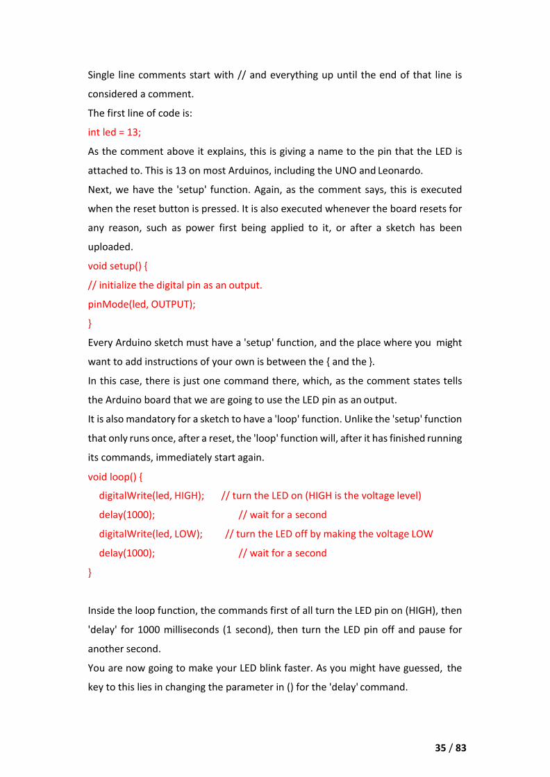
Single line comments start with // and everything up until the end of that line is
considered a comment.
The first line of code is:
int led = 13;
As the comment above it explains, this is giving a name to the pin that the LED is
attached to. This is 13 on most Arduinos, including the UNO and Leonardo.
Next, we have the 'setup' function. Again, as the comment says, this is executed
when the reset button is pressed. It is also executed whenever the board resets for
any reason, such as power first being applied to it, or after a sketch has been
uploaded.
void setup() {
// initialize the digital pin as an output.
pinMode(led, OUTPUT);
}
Every Arduino sketch must have a 'setup' function, and the place where you might
want to add instructions of your own is between the { and the }.
In this case, there is just one command there, which, as the comment states tells
the Arduino board that we are going to use the LED pin as an output.
It is also mandatory for a sketch to have a 'loop' function. Unlike the 'setup' function
that only runs once, after a reset, the 'loop' function will, after it has finished running
its commands, immediately start again.
void loop() {
digitalWrite(led, HIGH); // turn the LED on (HIGH is the voltage level)
delay(1000); // wait for a second
digitalWrite(led, LOW); // turn the LED off by making the voltage LOW
delay(1000); // wait for a second
}
Inside the loop function, the commands first of all turn the LED pin on (HIGH), then
'delay' for 1000 milliseconds (1 second), then turn the LED pin off and pause for
another second.
You are now going to make your LED blink faster. As you might have guessed, the
key to this lies in changing the parameter in () for the 'delay' command.

36 / 83
This delay period is in milliseconds, so if you want the LED to blink twice as fast,
change the value from 1000 to 500. This would then pause for half a second each
delay rather than a whole second.
Upload the sketch again and you should see the LED start to blink more quickly.
37 / 83
Lesson 3 LED
Overview
In this lesson, you will learn how to change the brightness of an LED by using
different values of resistor.
Component Required:
(1) x Elegoo Uno R3
(1) x 5mm red LED
(1) x 220 ohm resistor
(1) x 1k ohm resistor
(1) x 10k ohm resistor
(2) x M-M wires (Male to Male jumper wires)
Component Introduction
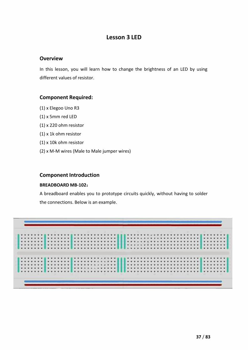
BREADBOARD MB-102:
A breadboard enables you to prototype circuits quickly, without having to solder
the connections. Below is an example.
38 / 83
Breadboards come in various sizes and configurations. The simplest kind is just a
grid of holes in a plastic block. Inside are strips of metal that provide electrical
connection between holes in the shorter rows. Pushing the legs of two different
components into the same row joins them together electrically. A deep channel
running down the middle indicates that there is a break in connections there,
meaning, you can push a chip in with the legs at either side of the channel without
connecting them together. Some breadboards have two strips of holes running
along the long edges of the board that are separated from the main grid. These have
strips running down the length of the board inside and provide a way to connect a
common voltage. They are usually in pairs for +5 volts and ground. These strips are
referred to as rails and they enable you to connect power to many components or
points in the board.
While breadboards are great for prototyping, they have some limitations. Because
the connections are push-fit and temporary, they are not as reliable as soldered
connections. If you are having intermittent problems with a circuit, it could be due
to a poor connection on a breadboard.
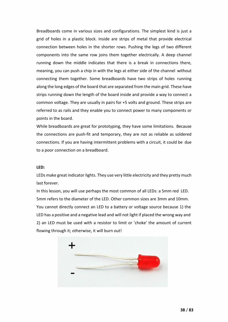
LED:
LEDs make great indicator lights. They use very little electricity and they pretty much
last forever.
In this lesson, you will use perhaps the most common of all LEDs: a 5mm red LED.
5mm refers to the diameter of the LED. Other common sizes are 3mm and 10mm.
You cannot directly connect an LED to a battery or voltage source because 1) the
LED has a positive and a negative lead and will not light if placed the wrong way and
2) an LED must be used with a resistor to limit or 'choke' the amount of current
flowing through it; otherwise, it will burn out!
39 / 83
If you do not use a resistor with an LED, then it may well be destroyed almost
immediately, as too much current will flow through, heating it and destroying the
'junction' where the light is produced.
There are two ways to tell which is the positive lead of the LED and which the
negative.
Firstly, the positive lead is longer.
Secondly, where the negative lead enters the body of the LED, there is a flat edge
to the case of the LED.
If you happen to have an LED that has a flat side next to the longer lead, you should
assume that the longer lead is positive.
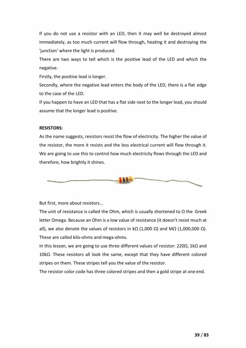
RESISTORS:
As the name suggests, resistors resist the flow of electricity. The higher the value of
the resistor, the more it resists and the less electrical current will flow through it.
We are going to use this to control how much electricity flows through the LED and
therefore, how brightly it shines.
But first, more about resistors...
The unit of resistance is called the Ohm, which is usually shortened to Ω the Greek
letter Omega. Because an Ohm is a low value of resistance (it doesn't resist much at
all), we also denote the values of resistors in kΩ (1,000 Ω) and MΩ (1,000,000 Ω).
These are called kilo-ohms and mega-ohms.
In this lesson, we are going to use three different values of resistor: 220Ω, 1kΩ and
10kΩ. These resistors all look the same, except that they have different colored
stripes on them. These stripes tell you the value of the resistor.
The resistor color code has three colored stripes and then a gold stripe at one end.

40 / 83
Unlike LEDs, resistors do not have a positive and negative lead. They can be
connected either way around.
If you find this approach method too complicated, you can read the color ring flag
on our resistors directly to determine its resistance value. Or you may use a digital
multimeter instead.
41 / 83
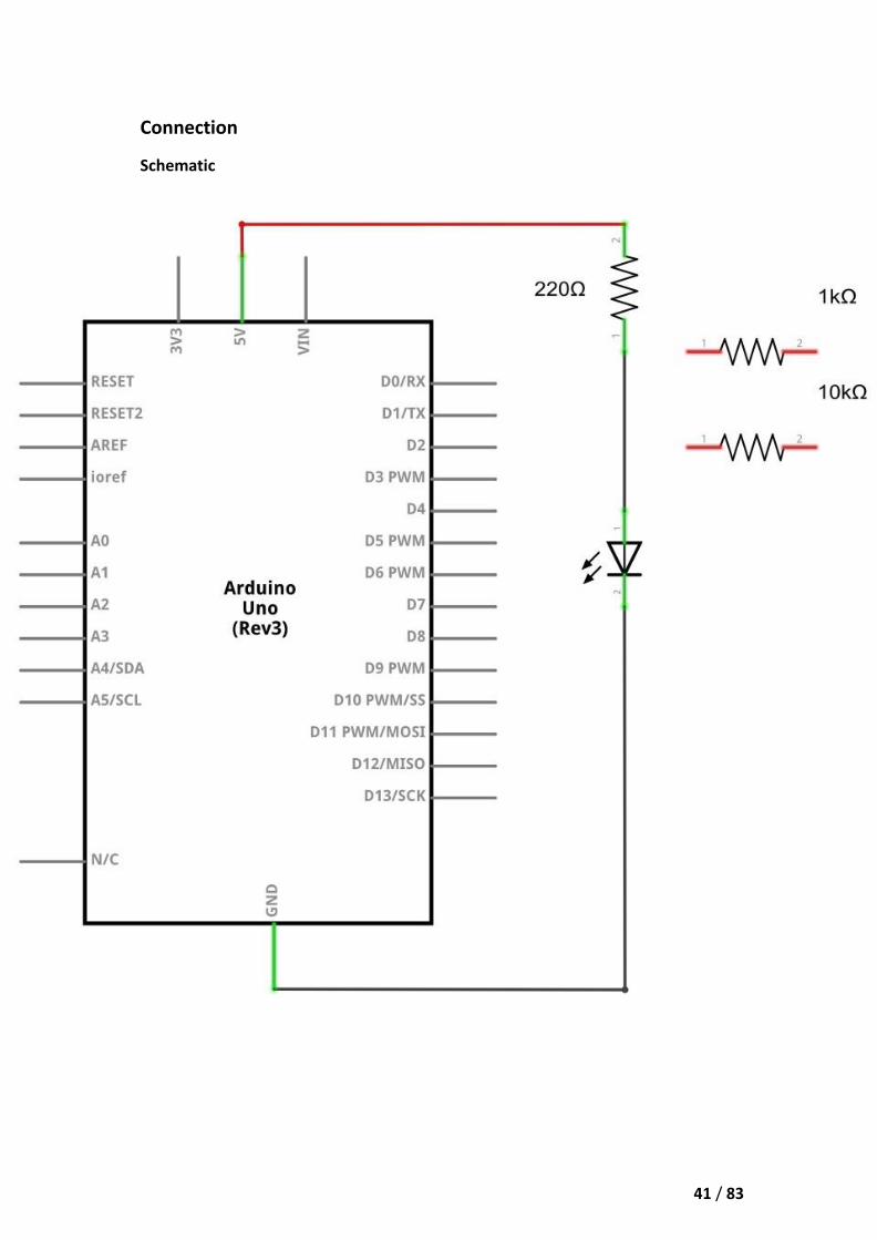
Connection
Schematic
42 / 83
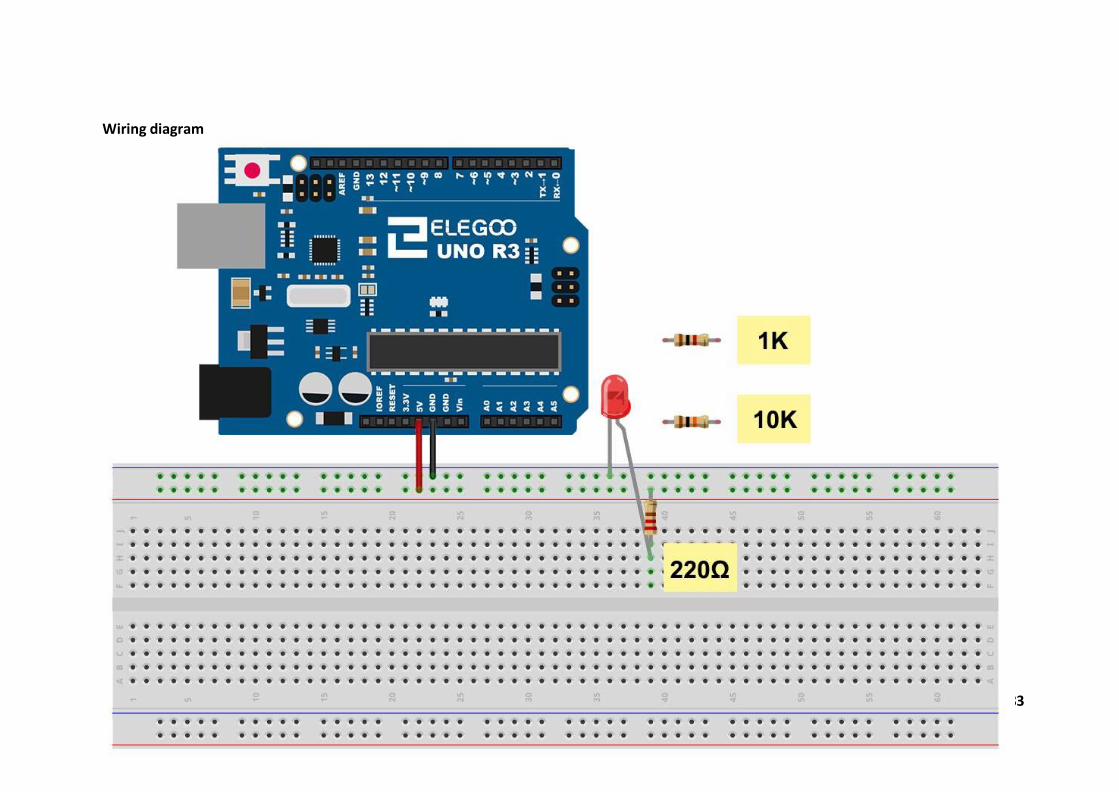
Wiring diagram
43 / 83
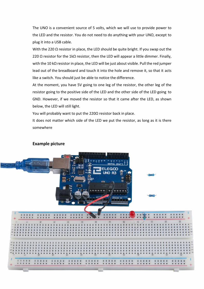
The UNO is a convenient source of 5 volts, which we will use to provide power to
the LED and the resistor. You do not need to do anything with your UNO, except to
plug it into a USB cable.
With the 220 Ω resistor in place, the LED should be quite bright. If you swap out the
220 Ω resistor for the 1kΩ resistor, then the LED will appear a little dimmer. Finally,
with the 10 kΩ resistor in place, the LED will be just about visible. Pull the red jumper
lead out of the breadboard and touch it into the hole and remove it, so that it acts
like a switch. You should just be able to notice the difference.
At the moment, you have 5V going to one leg of the resistor, the other leg of the
resistor going to the positive side of the LED and the other side of the LED going to
GND. However, if we moved the resistor so that it came after the LED, as shown
below, the LED will still light.
You will probably want to put the 220Ω resistor back in place.
It does not matter which side of the LED we put the resistor, as long as it is there
somewhere
Example picture

44 / 83
Lesson 4 RGB LED
Overview
RGB LEDs are a fun and easy way to add some color to your projects. Since they are
like 3 regular LEDs in one, how to use and connect them is not much different.
They come mostly in 2 versions: Common Anode or Common Cathode.
Common Anode uses 5V on the common pin, while Common Cathode connects to
ground.
As with any LED, we need to connect some resistors inline (3 total) so we can limit
the current being drawn.
In our sketch, we will start with the LED in the Red color state, then fade to Green,
then fade to Blue and finally back to the Red color. By doing this we will cycle
through most of the color that can be achieved.
Component Required:
(1) x Elegoo Uno R3
(1) x 830 Tie Points Breadboard
(4) x M-M wires (Male to Male jumper wires)
(1) x RGB LED
(3) x 220 ohm resistors

45 / 83
Component Introduction
RGB:
At first glance, RGB (Red, Green and Blue) LEDs look just like regular LEDs. However,
inside the usual LED package, there are actually three LEDs, one red, one green and
yes, one blue. By controlling the brightness of each of the individual LEDs you can
mix pretty much any color you want.
We mix colors the same way you would mix paint on a palette - by adjusting the
brightness of each of the three LEDs. The hard way to do this would be to use
different value resistors (or variable resistors) as we did with in Lesson 2, but that's
a lot of work! Fortunately for us, UNO R3 board has an analogWrite function that
you can use with pins marked with a ~ to output a variable amount of power to the
appropriate LEDs.
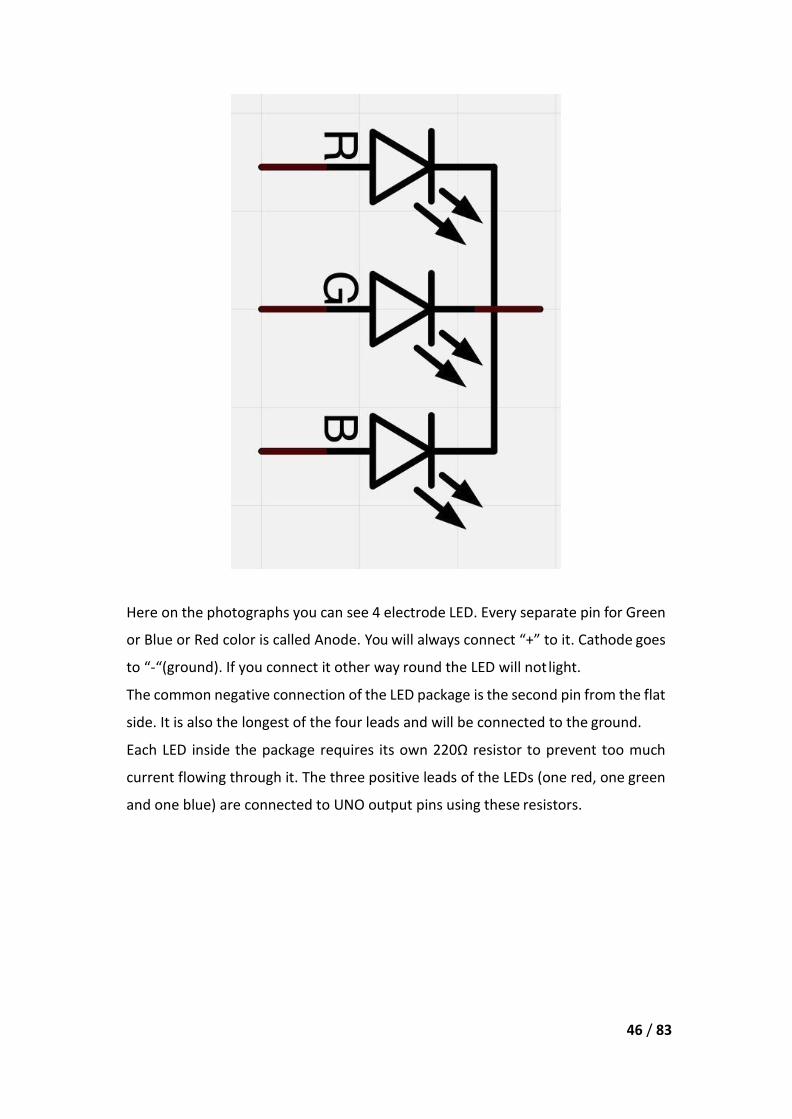
The RGB LED has four leads. There is one lead going to the positive connection of
each of the single LEDs within the package and a single lead that is connected to all
three negative sides of the LEDs.
46 / 83
Here on the photographs you can see 4 electrode LED. Every separate pin for Green
or Blue or Red color is called Anode. You will always connect “+” to it. Cathode goes
to “-“(ground). If you connect it other way round the LED will not light.
The common negative connection of the LED package is the second pin from the flat
side. It is also the longest of the four leads and will be connected to the ground.
Each LED inside the package requires its own 220Ω resistor to prevent too much
current flowing through it. The three positive leads of the LEDs (one red, one green
and one blue) are connected to UNO output pins using these resistors.

47 / 83
COLOR:
The reason that you can mix any color you like by varying the quantities of red, green
and blue light is that your eye has three types of light receptor in it (red, green and
blue). Your eye and brain process the amounts of red, green and blue and convert
it into a color of the spectrum.
In a way, by using the three LEDs, we are playing a trick on the eye. This same idea
is used in TVs, where the LCD has red, green and blue color dots next to each other
making up each pixel.
If we set the brightness of all three LEDs to be the same, then the overall color of
the light will be white. If we turn off the blue LED, so that just the red and green
LEDs are the same brightness, then the light will appear yellow.
We can control the brightness of each of the red, green and blue parts of the LED
separately, making it possible to mix any color we like.
Black is not so much a color as an absence of light. Therefore, the closest we can
come to black with our LED is to turn off all three colors.

48 / 83
Theory (PWM)
Pulse Width Modulation (PWM) is a technique for controlling power.
We also use it here to control the brightness of each of the LEDs.
The diagram below shows the signal from one of the PWM pins on the UNO.
Roughly every 1/500 of a second, the PWM output will produce a pulse. The length
of this pulse is controlled by the 'analogWrite' function. So 'analogWrite(0)' will not
produce any pulse at all and 'analogWrite(255)' will produce a pulse that lasts all the
way until the next pulse is due, so that the output is actually on all the time.
If we specify a value in the analogWrite that is somewhere in between 0 and 255,
then we will produce a pulse. If the output pulse is only high for 5% of the time, then
whatever we are driving will only receive 5% of full power.
If, however, the output is at 5V for 90% of the time, then the load will get 90% of
the power delivered to it. We cannot see the LEDs turning on and off at that speed,
so to us, it just looks like the brightness is changing.

49 / 83
Connection
Schematic
50 / 83
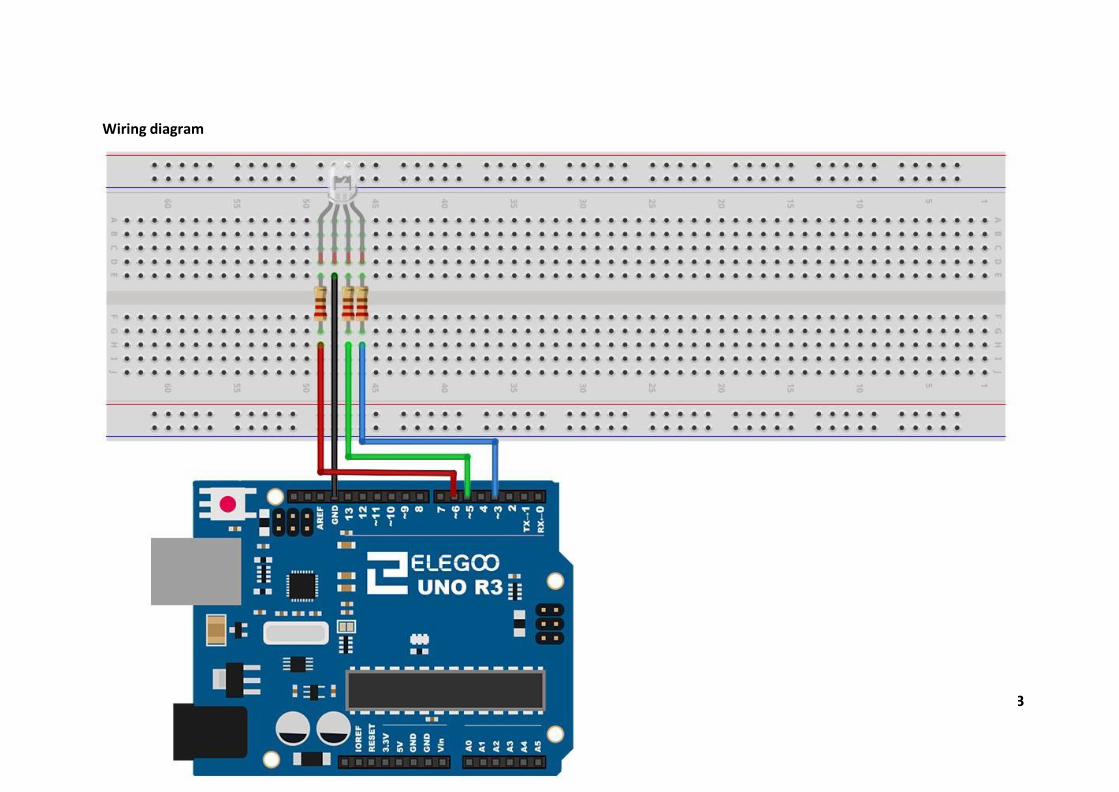
Wiring diagram
51 / 83
Code
After wiring, please open the program in the code folder- Lesson 4 RGB LED, and
click UPLOAD to upload the program. See Lesson 2 for details about program
uploading if there are any errors.
Our code will use FOR loops to cycle through the colors.
The first FOR loop will go from RED to GREEN.
The second FOR loop will go from GREEN to BLUE.
The last FOR loop will go from BLUE to RED.
Try the sketch out and then we will dissect it in some detail......
The sketch starts by specifying which pins are going to be used for each of the colors:
// Define Pins
#define BLUE 3
#define GREEN 5
#define RED 6
The next step is to write the 'setup' function. As we have learnt in earlier lessons,
the setup function runs just once after the Arduino has reset. In this case, all it has
to do is define the three pins we are using as being outputs.
void setup()
{
pinMode(RED, OUTPUT);
pinMode(GREEN, OUTPUT);
pinMode(BLUE, OUTPUT);
digitalWrite(RED, HIGH);
digitalWrite(GREEN, LOW);
digitalWrite(BLUE, LOW);
}
Before we take a look at the 'loop' function, let’s look at the last function in the
sketch.
The define variables
redValue = 255; // choose a value between 1 and 255 to change the color.
greenValue = 0;

52 / 83
blueValue = 0;
This function takes three arguments, one for the brightness of the red, green and
blue LEDs. In each case the number will be in the range 0 to 255, where 0 means off
and 255 means maximum brightness. The function then calls 'analogWrite' to set
the brightness of each LED.
If you look at the 'loop' function you can see that we are setting the amount of red,
green and blue light that we want to display and then pausing for a second before
moving on to the next color.
#define delayTime 10 // fading time between colors
Delay(delayTime);
Try adding a few colors of your own to the sketch and watch the effect on your LED.
Example picture
53 / 83
Lesson 5 Digital Inputs
Overview
In this lesson, you will learn to use push buttons with digital inputs to turn an LED
on and off.
Pressing the button will turn the LED on; pressing the other button will turn the LED
off.
Component Required:
(1) x Elegoo Uno R3
(1) x 830 Tie-points Breadboard
(1) x 5mm red LED
(1) x 220 ohm resistor
(2) x push switches
(7) x M-M wires (Male to Male jumper wires)
Component Introduction
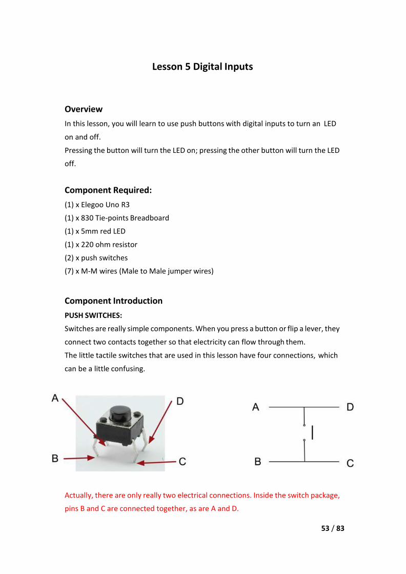
PUSH SWITCHES:
Switches are really simple components. When you press a button or flip a lever, they
connect two contacts together so that electricity can flow through them.
The little tactile switches that are used in this lesson have four connections, which
can be a little confusing.
Actually, there are only really two electrical connections. Inside the switch package,
pins B and C are connected together, as are A and D.

54 / 83
Connection
Schematic
55 / 83
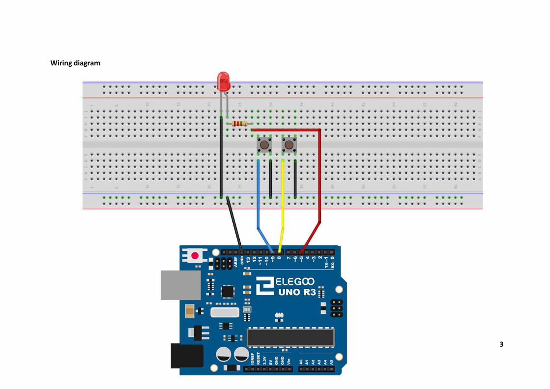
Wiring diagram
56 / 83
Although the bodies of the switches are square, the pins protrude from opposite
sides of the switch. This means that the pins will only be far enough apart when they
are placed correctly on the breadboard.
Remember that the LED has to have the shorter negative lead to the left.
Code
After wiring,please open program in the code folder- Lesson 5 Digital Inputs, and
press UPLOAD to upload the program. If errors are prompted, see Lesson 2 for
details about the tutorial on program upload.
Load the sketch onto your UNO board. Pressing the left button will turn the LED on
while pressing the right button will turn it off.
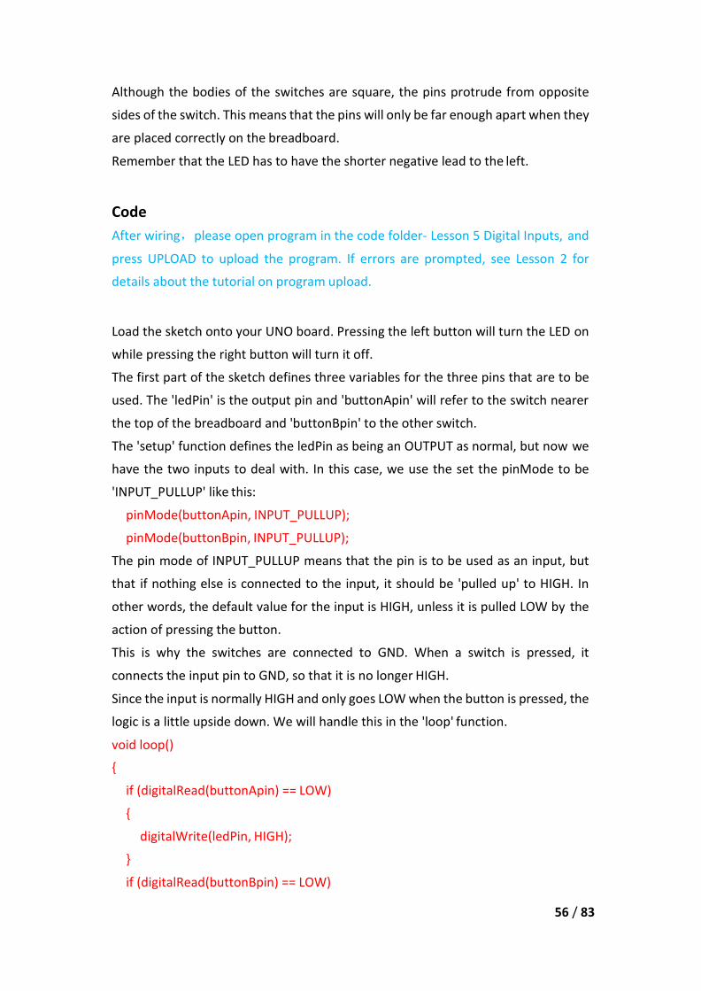
The first part of the sketch defines three variables for the three pins that are to be
used. The 'ledPin' is the output pin and 'buttonApin' will refer to the switch nearer
the top of the breadboard and 'buttonBpin' to the other switch.
The 'setup' function defines the ledPin as being an OUTPUT as normal, but now we
have the two inputs to deal with. In this case, we use the set the pinMode to be
'INPUT_PULLUP' like this:
pinMode(buttonApin, INPUT_PULLUP);
pinMode(buttonBpin, INPUT_PULLUP);
The pin mode of INPUT_PULLUP means that the pin is to be used as an input, but
that if nothing else is connected to the input, it should be 'pulled up' to HIGH. In
other words, the default value for the input is HIGH, unless it is pulled LOW by the
action of pressing the button.
This is why the switches are connected to GND. When a switch is pressed, it
connects the input pin to GND, so that it is no longer HIGH.
Since the input is normally HIGH and only goes LOW when the button is pressed, the
logic is a little upside down. We will handle this in the 'loop' function.
void loop()
{
if (digitalRead(buttonApin) == LOW)
{
digitalWrite(ledPin, HIGH);
}
if (digitalRead(buttonBpin) == LOW)
57 / 83
{
digitalWrite(ledPin, LOW);
}
}
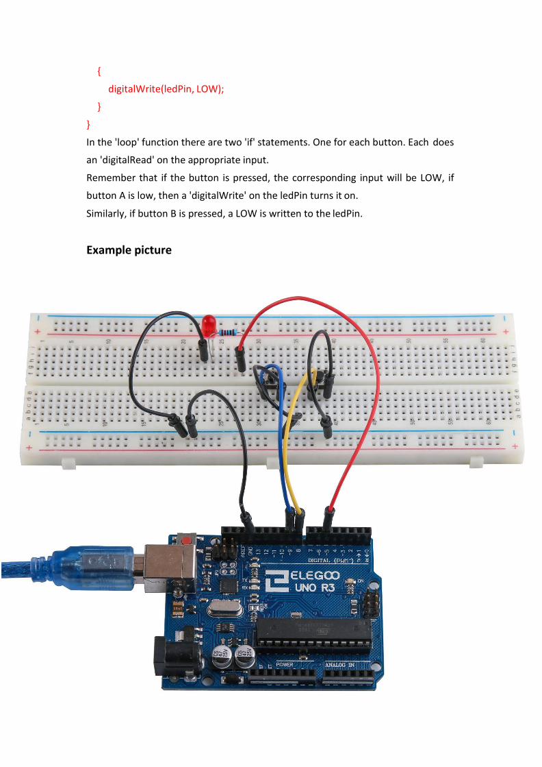
In the 'loop' function there are two 'if' statements. One for each button. Each does
an 'digitalRead' on the appropriate input.
Remember that if the button is pressed, the corresponding input will be LOW, if
button A is low, then a 'digitalWrite' on the ledPin turns it on.
Similarly, if button B is pressed, a LOW is written to the ledPin.
Example picture

Lesson 6 Active buzzer
Overview
In this lesson, you will learn how to generate a sound with an active buzzer.
Component Required:
(1) x Elegoo Uno R3
(1) x Active buzzer
(2) x F-M wires (Female to Male DuPont wires)
Component Introduction
BUZZER:
Electronic buzzers are DC-powered and equipped with an integrated circuit. They
are widely used in computers, printers, photocopiers, alarms, electronic toys,
automotive electronic devices, telephones, timers and other electronic products for
voice devices. Buzzers can be categorized as active and passive ones. Turn the pins
of two buzzers face up. The one with a green circuit board is a passive buzzer, while
the other enclosed with a black tape is an active one.
The difference between the two is that an active buzzer has a built-in oscillating
source, so it will generate a sound when electrified. A passive buzzer does not have
such a source so it will not tweet if DC signals are used; instead, you need to use
square waves whose frequency is between 2K and 5K to drive it. The active buzzer
is often more expensive than the passive one because of multiple built-in oscillating
circuits.
58 / 83
59 / 83
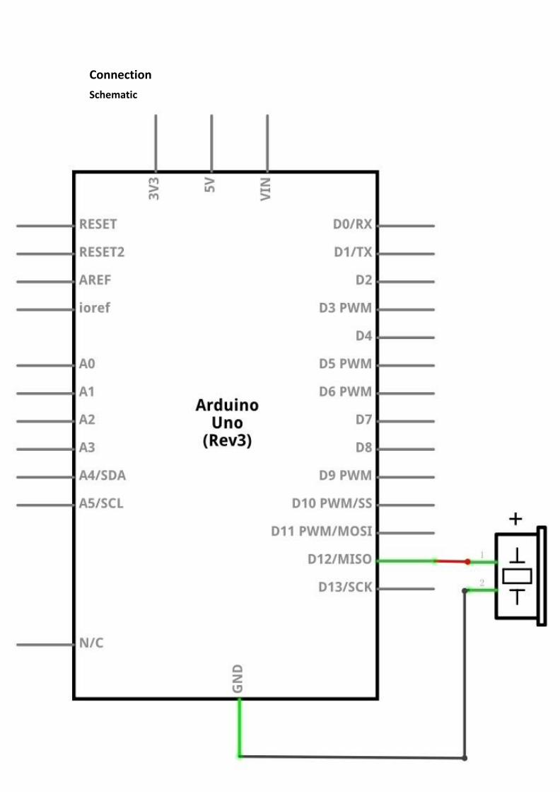
Connection
Schematic

60 / 83
Wiring diagram
61 / 83
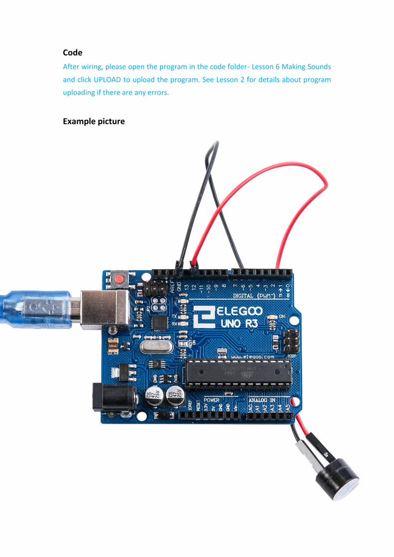
Code
After wiring, please open the program in the code folder- Lesson 6 Making Sounds
and click UPLOAD to upload the program. See Lesson 2 for details about program
uploading if there are any errors.
Example picture
62 / 83
Lesson 7 Ball Switch
Overview
In this lesson, you will learn how to use a tilt ball switch in order to detect small
angle of inclination.
Component Required:
(1) x Elegoo Uno R3
(1) x Tilt Ball switch
(2) x F-M wires (Female to Male DuPont wires)
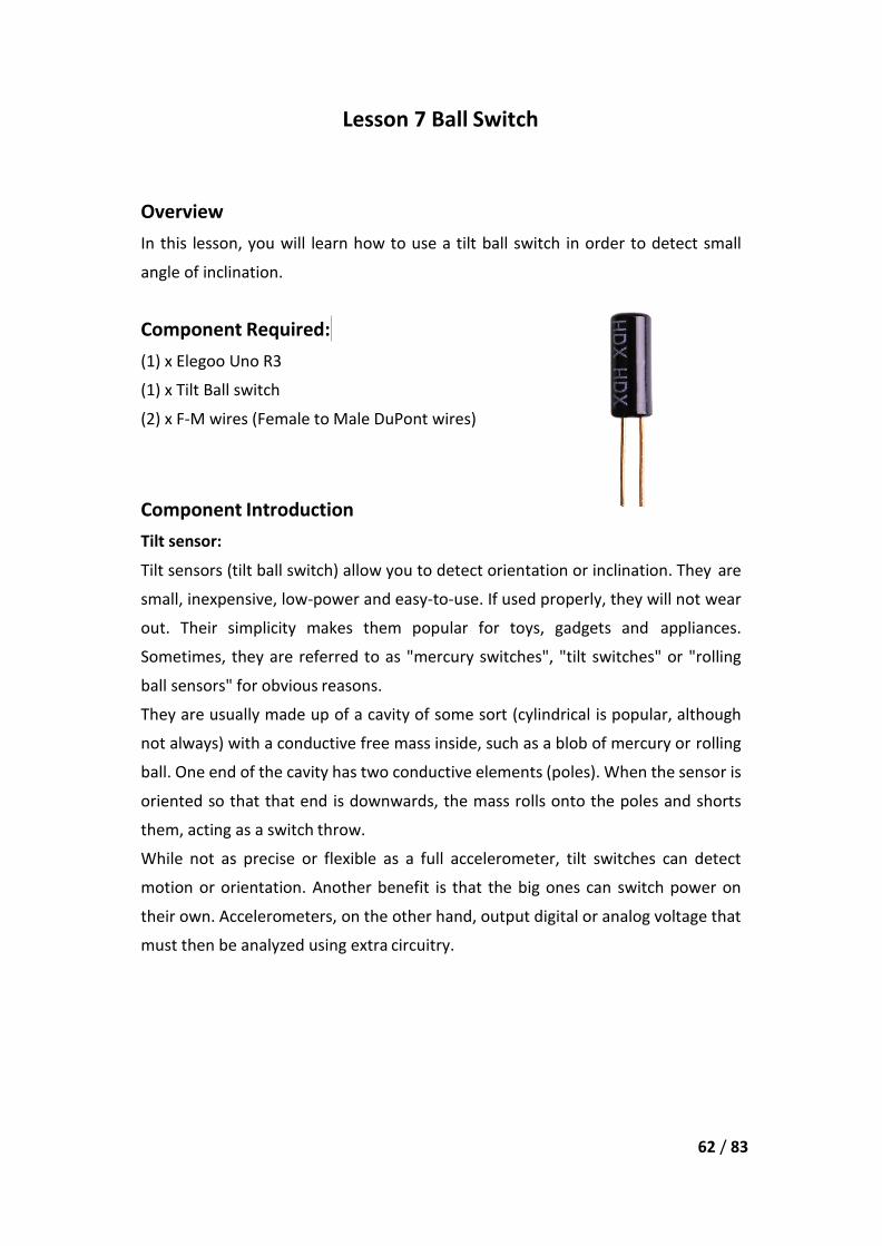
Component Introduction
Tilt sensor:
Tilt sensors (tilt ball switch) allow you to detect orientation or inclination. They are
small, inexpensive, low-power and easy-to-use. If used properly, they will not wear
out. Their simplicity makes them popular for toys, gadgets and appliances.
Sometimes, they are referred to as "mercury switches", "tilt switches" or "rolling
ball sensors" for obvious reasons.
They are usually made up of a cavity of some sort (cylindrical is popular, although
not always) with a conductive free mass inside, such as a blob of mercury or rolling
ball. One end of the cavity has two conductive elements (poles). When the sensor is
oriented so that that end is downwards, the mass rolls onto the poles and shorts
them, acting as a switch throw.
While not as precise or flexible as a full accelerometer, tilt switches can detect
motion or orientation. Another benefit is that the big ones can switch power on
their own. Accelerometers, on the other hand, output digital or analog voltage that
must then be analyzed using extra circuitry.
63 / 83
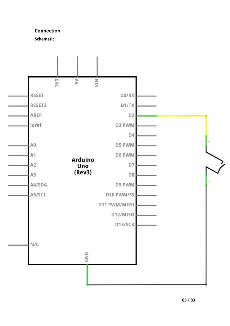
Connection
Schematic

64 / 83
Wiring diagram

65 / 83
Code
After wiring, please open the program in the code folder- Lesson 8 Ball Switch and
click UPLOAD to upload the program. See Lesson 2 for details about program
uploading if there are any errors.
Example picture

66 / 83
Lesson 8 Eight LED with 74HC595
Overview
In this lesson, you will learn how to use eight large red LEDs with an UNO without
needing to give up 8 output pins!
Although you could wire up eight LEDs each with a resistor to an UNO pin you would
rapidly start to run out of pins on your UNO. If you don't have a lot of stuff connected
to your UNO. It's OK to do so - but often times we want buttons, sensors, servos,
etc. and before you know it you've got no pins left. So, instead of doing that, you
are going to use a chip called the 74HC595 Serial to Parallel Converter. This chip has
eight outputs (perfect) and three inputs that you use to feed data into it a bit at a
time.
This chip makes it a little slower to drive the LEDs (you can only change the LEDs
about 500,000 times a second instead of 8,000,000 a second) but it's still really fast,
way faster than humans can detect, so it's worth it!
Component Required:
(1) x Elegoo Uno R3
(1) x 830 tie-points breadboard
(8) x leds
(8) x 220 ohm resistors
(1) x 74hc595 IC
(14) x M-M wires (Male to Male jumper wires)
Component Introduction
74HC595 Shift Register:
The shift register is a type of chip that holds what can be thought of as eight memory
locations, each of which can either be a 1 or a 0. To set each of these values on or
off, we feed in the data using the 'Data' and 'Clock' pins of the chip.

67 / 83
68 / 83
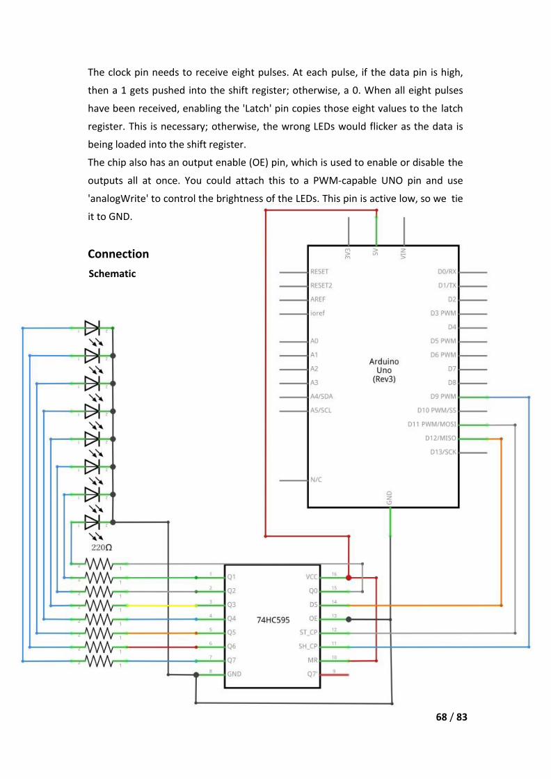
The clock pin needs to receive eight pulses. At each pulse, if the data pin is high,
then a 1 gets pushed into the shift register; otherwise, a 0. When all eight pulses
have been received, enabling the 'Latch' pin copies those eight values to the latch
register. This is necessary; otherwise, the wrong LEDs would flicker as the data is
being loaded into the shift register.
The chip also has an output enable (OE) pin, which is used to enable or disable the
outputs all at once. You could attach this to a PWM-capable UNO pin and use
'analogWrite' to control the brightness of the LEDs. This pin is active low, so we tie
it to GND.
Connection
Schematic

69 / 83
Wiring diagram
As we have eight LEDs and eight resistors to connect, there are actually quite a few
connections to be made.
It is probably easiest to put the 74HC595 chip in first, as pretty much everything else
connects to it. Put it so that the little U-shaped notch is towards the top of the
breadboard. Pin 1 of the chip is to the left of this notch.
Digital 12 from the UNO goes to pin #14 of the shift register
Digital 11 from the UNO goes to pin #12 of the shift register
Digital 9 from the UNO goes to pin #11 of the shift register
All but one of the outputs from the IC is on the left side of the chip. Hence, for ease
of connection, that is where the LEDs are, too.
After the chip, put the resistors in place. You need to be careful that none of the
leads of the resistors are touching each other. You should check this again before
you connect the power to your UNO. If you find it difficult to arrange the resistors
without their leads touching, then it helps to shorten the leads so that they are lying
closer to the surface of the breadboard.
Next, place the LEDs on the breadboard. The longer positive LED leads must all be
towards the chip, whichever side of the breadboard they are on.
Attach the jumper leads as shown above. Do not forget the one that goes from pin
8 of the IC to the GND column of the breadboard.
Load up the sketch listed a bit later and try it out. Each LED should light in turn until
all the LEDs are on, and then they all go off and the cycle repeats.
Code
After wiring, please open the program in the code folder- Lesson 24 Eight LED with
74HC595 and click UPLOAD to upload the program. See Lesson 2 for details about
program uploading if there are any errors.
The first thing we do is define the three pins we are going to use. These are the UNO
digital outputs that will be connected to the latch, clock and data pins of the
74HC595.
int latchPin = 11;
int clockPin = 9;
int dataPin = 12;
Next, a variable called 'leds' is defined. This will be used to hold the pattern of which
LEDs are currently turned on or off. Data of type 'byte' represents numbers using
eight bits. Each bit can be either on or off, so this is perfect for keeping track of

71 / 83
which of our eight LEDs are on or off.
byte leds = 0;
The 'setup' function just sets the three pins we are using to be digital outputs.
void setup()
{
pinMode(latchPin, OUTPUT);
pinMode(dataPin, OUTPUT);
pinMode(clockPin, OUTPUT);
}
The 'loop' function initially turns all the LEDs off, by giving the variable 'leds' the
value 0. It then calls 'updateShiftRegister' that will send the 'leds' pattern to the shift
register so that all the LEDs turn off. We will deal with how 'updateShiftRegister'
works later.
The loop function pauses for half a second and then begins to count from 0 to 7
using the 'for' loop and the variable 'i'. Each time, it uses the Arduino function
'bitSet' to set the bit that controls that LED in the variable 'leds'. It then also calls
'updateShiftRegister' so that the leds update to reflect what is in the variable 'leds'.
There is then a half second delay before 'i' is incremented and the next LED is lit.
void loop()
{
leds = 0;
updateShiftRegister();
delay(500);
for (int i = 0; i < 8; i++)
{
bitSet(leds, i);
updateShiftRegister();
delay(500);
}
}
The function 'updateShiftRegister', first of all sets the latchPin to low, then calls the
UNO function 'shiftOut' before putting the 'latchPin' high again. This takes four
parameters, the first two are the pins to use for Data and Clock respectively.
The third parameter specifies which end of the data you want to start at. We are
going to start with the right most bit, which is referred to as the 'Least Significant
72 / 83
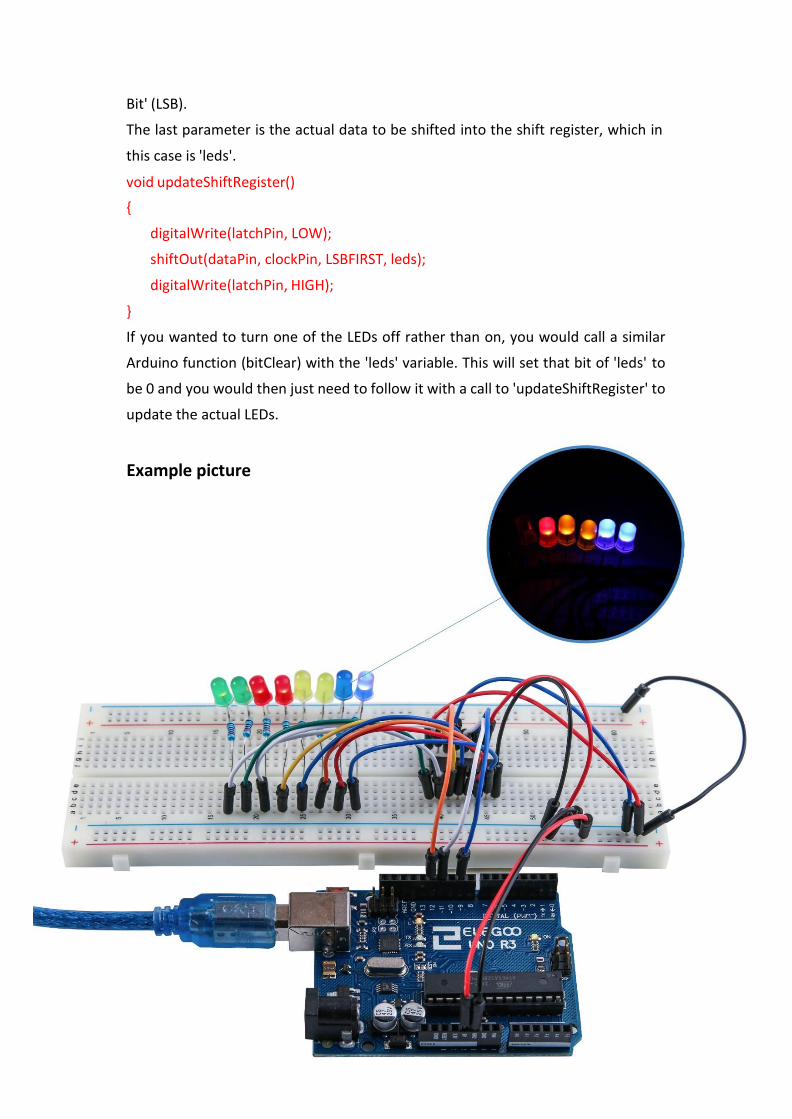
Example picture
Bit' (LSB).
The last parameter is the actual data to be shifted into the shift register, which in
this case is 'leds'.
void updateShiftRegister()
{
digitalWrite(latchPin, LOW);
shiftOut(dataPin, clockPin, LSBFIRST, leds);
digitalWrite(latchPin, HIGH);
}
If you wanted to turn one of the LEDs off rather than on, you would call a similar
Arduino function (bitClear) with the 'leds' variable. This will set that bit of 'leds' to
be 0 and you would then just need to follow it with a call to 'updateShiftRegister' to
update the actual LEDs.
73 / 83
Lesson 9 The Serial Monitor
Overview
In this lesson, you will build on Lesson 8, adding the facility to control the LEDs
from your computer using the Arduino Serial Monitor. The serial monitor is
the 'tether' between the computer and your UNO. It lets you send and
receive text messages, handy for debugging and also controlling the UNO from a
keyboard! For example, you will be able to send commands from your computer
to turn on LEDs. In this lesson, you will use exactly the same parts and a similar
breadboard layout as Lesson 8. So, if you have not already done so, follow Lesson
8 now.
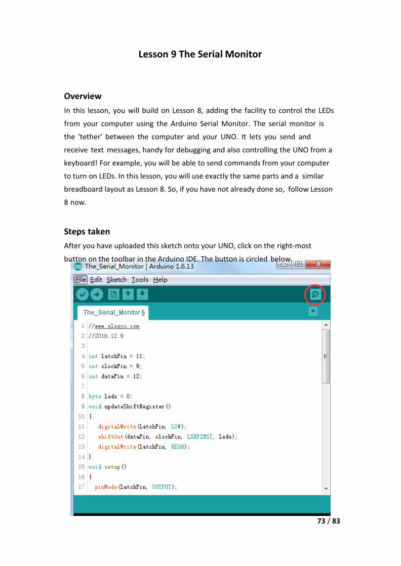
Steps taken
After you have uploaded this sketch onto your UNO, click on the right-most
button on the toolbar in the Arduino IDE. The button is circled below.
74 / 83
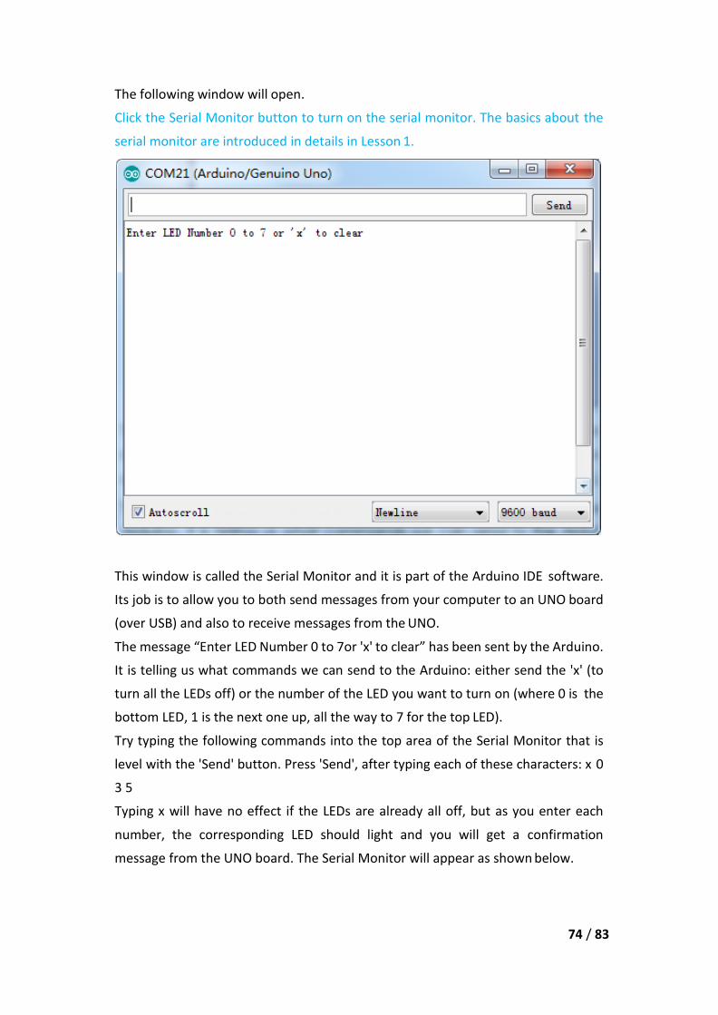
The following window will open.
Click the Serial Monitor button to turn on the serial monitor. The basics about the
serial monitor are introduced in details in Lesson 1.
This window is called the Serial Monitor and it is part of the Arduino IDE software.
Its job is to allow you to both send messages from your computer to an UNO board
(over USB) and also to receive messages from the UNO.
The message “Enter LED Number 0 to 7or 'x' to clear” has been sent by the Arduino.
It is telling us what commands we can send to the Arduino: either send the 'x' (to
turn all the LEDs off) or the number of the LED you want to turn on (where 0 is the
bottom LED, 1 is the next one up, all the way to 7 for the top LED).
Try typing the following commands into the top area of the Serial Monitor that is
level with the 'Send' button. Press 'Send', after typing each of these characters: x 0
3 5
Typing x will have no effect if the LEDs are already all off, but as you enter each
number, the corresponding LED should light and you will get a confirmation
message from the UNO board. The Serial Monitor will appear as shown below.

75 / 83
Type x again and press ‘Send’ to turn off all LEDs.
Code
After wiring, please open program in the code folder- Lesson 25 The Serial Monitor
and click UPLOAD to upload the program. See Lesson 2 for details about program
uploading if there are any errors.
As you might expect, the sketch is based on the sketch used in Lesson 24. So, we will
just cover the new bits here. You will find it useful to refer to the full sketch in your
Arduino IDE.
In the 'setup' function, there are three new lines at the end:
void setup()
{
pinMode(latchPin, OUTPUT);
pinMode(dataPin, OUTPUT);
pinMode(clockPin, OUTPUT);
updateShiftRegister();
Serial.begin(9600);

76 / 83
while (! Serial); // Wait until Serial is ready - Leonardo
Serial.println("Enter LED Number 0 to 7 or 'x' to clear");
}
Firstly, we have the command 'Serial.begin(9600)'. This starts serial communication,
so that the UNO can send out commands through the USB connection. The value
9600 is called the 'baud rate' of the connection. This is how fast the data is to be
sent. You can change this to a higher value, but you will also have to change the
Arduino Serial monitor to the same value. We will discuss this later; for now, leave
it at 9600.
The line beginning with 'while' ensures that there is something at the other end of
the USB connection for the Arduino to talk to before it starts sending messages.
Otherwise, the message might be sent, but not displayed. This line is actually only
necessary if you are using an Arduino Leonardo because the Arduino UNO
automatically resets the Arduino board when you open the Serial Monitor, whereas
this does not happen with the Leonardo.
The last of the new lines in 'setup' sends out the message that we see at the top of
the Serial Monitor.
The 'loop' function is where all the action happens:
void loop()
{
if (Serial.available())
{
char ch = Serial.read();
if (ch >= '0' && ch <= '7')
{
int led = ch - '0';
bitSet(leds, led);
updateShiftRegister();
Serial.print("Turned on LED ");
Serial.println(led);
}
if (ch == 'x')
{
leds = 0;
updateShiftRegister();
77 / 83
Serial.println("Cleared");
}
}
}
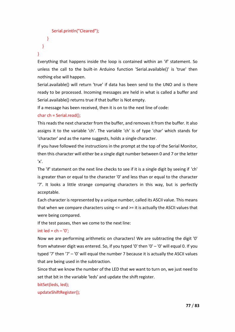
Everything that happens inside the loop is contained within an 'if' statement. So
unless the call to the built-in Arduino function 'Serial.available()' is 'true' then
nothing else will happen.
Serial.available() will return 'true' if data has been send to the UNO and is there
ready to be processed. Incoming messages are held in what is called a buffer and
Serial.available() returns true if that buffer is Not empty.
If a message has been received, then it is on to the next line of code:
char ch = Serial.read();
This reads the next character from the buffer, and removes it from the buffer. It also
assigns it to the variable 'ch'. The variable 'ch' is of type 'char' which stands for
'character' and as the name suggests, holds a single character.
If you have followed the instructions in the prompt at the top of the Serial Monitor,
then this character will either be a single digit number between 0 and 7 or the letter
'x'.
The 'if' statement on the next line checks to see if it is a single digit by seeing if 'ch'
is greater than or equal to the character '0' and less than or equal to the character
'7'. It looks a little strange comparing characters in this way, but is perfectly
acceptable.
Each character is represented by a unique number, called its ASCII value. This means
that when we compare characters using <= and >= it is actually the ASCII values that
were being compared.
If the test passes, then we come to the next line:
int led = ch – '0';
Now we are performing arithmetic on characters! We are subtracting the digit '0'
from whatever digit was entered. So, if you typed '0' then '0' – '0' will equal 0. If you
typed '7' then '7' – '0' will equal the number 7 because it is actually the ASCII values
that are being used in the subtraction.
Since that we know the number of the LED that we want to turn on, we just need to
set that bit in the variable 'leds' and update the shift register.
bitSet(leds, led);
updateShiftRegister();
78 / 83
The next two lines write back a confirmation message to the Serial Monitor.
Serial.print("Turned on LED ");
Serial.println(led);
The first line uses Serial.print rather than Serial.println. The different between the
two is that Serial.print does not start a new line after printing whatever is in its
parameter. We use this in the first line, because we are printing the message in two
parts. Firstly the general bit: 'Turned on LED ' and then the number of the LED.
The number of the LED is held in an 'int' variable rather than being a text string.
Serial.print can take either a text string enclosed in double-quotes, or an 'int' or for
that matter pretty much any type of variable.
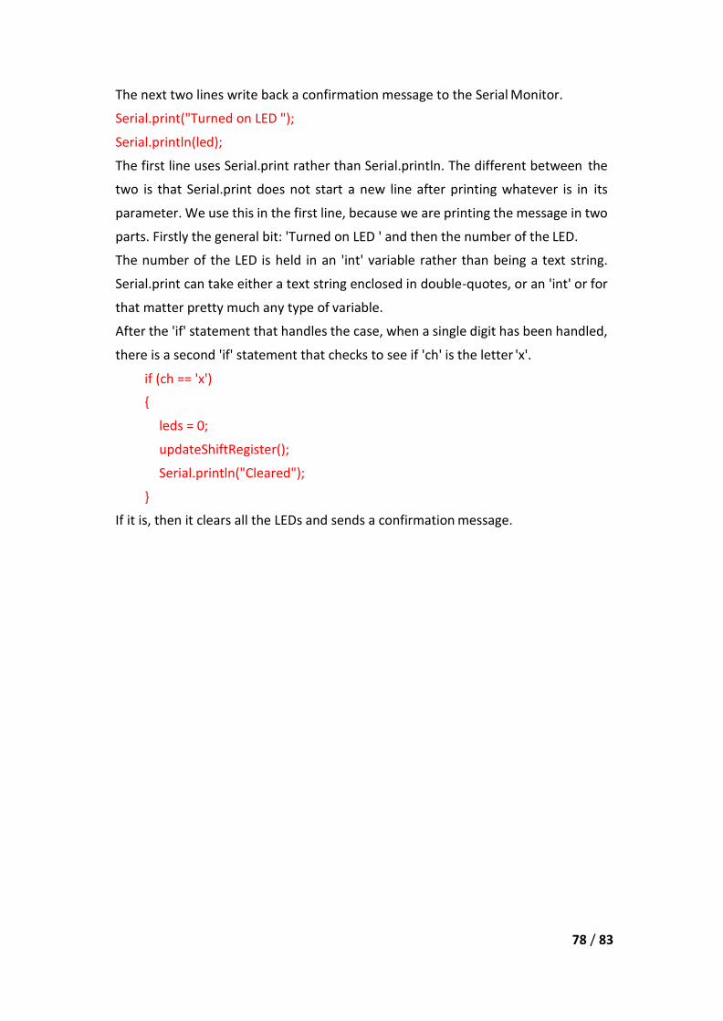
After the 'if' statement that handles the case, when a single digit has been handled,
there is a second 'if' statement that checks to see if 'ch' is the letter 'x'.
if (ch == 'x')
{
leds = 0;
updateShiftRegister();
Serial.println("Cleared");
}
If it is, then it clears all the LEDs and sends a confirmation message.

79 / 83
Lesson 10 Photocell
Overview
In this lesson, you will learn how to measure light intensity using an Analog Input.
You will build on lesson 8 and use the level of light to control the number of LEDs
to be lit.
The photocell is at the bottom of the breadboard, where the pot was above.
Component Required:
(1) x Elegoo Uno R3
(1) x 830 tie-points breadboard
(8) x leds
(8) x 220 ohm resistors
(1) x 1k ohm resistor
(1) x 74hc595 IC
(1) x Photoresistor (Photocell)
(16) x M-M wires (Male to Male jumper wires)
Component Introduction
PHOTOCELL:
The photocell used is of a type called a light dependent resistor, sometimes called
an LDR. As the name suggests, these components act just like a resistor, except that
the resistance changes in response to how much light is falling on them.
This one has a resistance of about 50 kΩ in near darkness and 500 Ω in bright light.
To convert this varying value of resistance into something we can measure on an
UNO R3 board's analog input, it needs to be converted into a voltage.
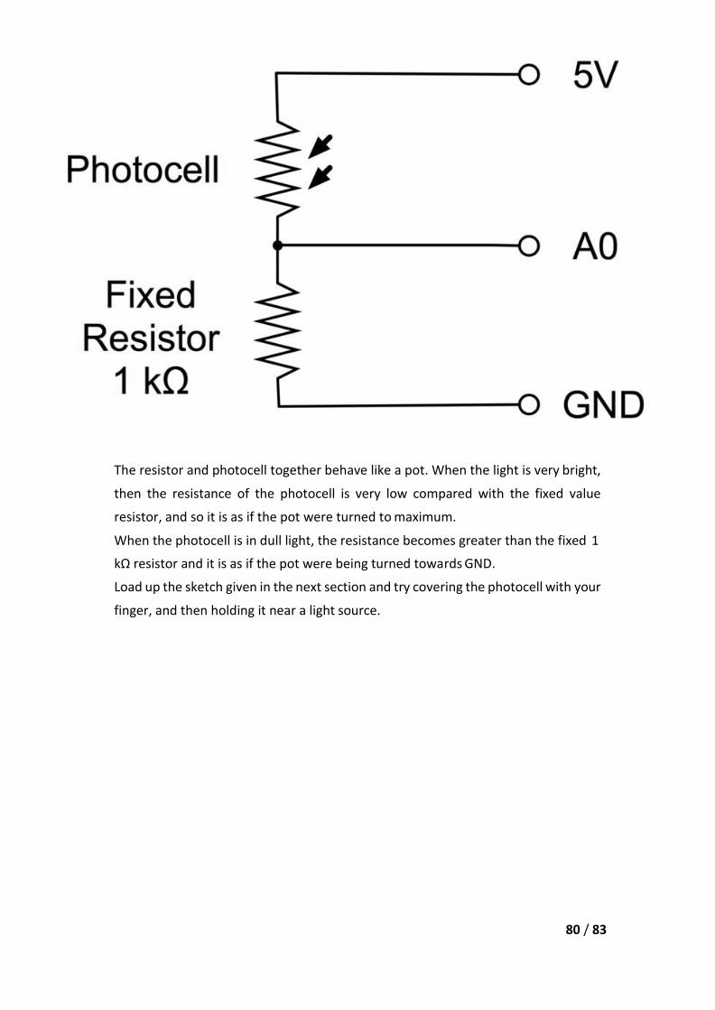
The simplest way to do that is to combine it with a fixed resistor.
80 / 83
The resistor and photocell together behave like a pot. When the light is very bright,
then the resistance of the photocell is very low compared with the fixed value
resistor, and so it is as if the pot were turned to maximum.
When the photocell is in dull light, the resistance becomes greater than the fixed 1
kΩ resistor and it is as if the pot were being turned towards GND.
Load up the sketch given in the next section and try covering the photocell with your
finger, and then holding it near a light source.

81 / 83
Connection Schematic

82 / 83
Wiring diagram

83 / 83
Code
After wiring, please open the program in the code folder- Lesson 26 Photocell and
click UPLOAD to upload the program. See Lesson 2 for details about program
uploading if there are any errors.
The first thing to note is that we have changed the name of the analog pin to be
'lightPin' rather than 'potPin' since we no longer have a pot connected.
The only other substantial change to the sketch is the line that calculates how many
of the LEDs to light:
int numLEDSLit = reading / 57; // all LEDs lit at 1k
This time, we divide the raw reading by 57 rather than 114. In other words, we divide
it by half as much as we did with the pot to split it into nine zones, from no LEDs lit
to all eight lit. This extra factor is to account for the fixed 1 kΩ resistor. This means
that when the photocell has a resistance of 1 kΩ (the same as the fixed resistor), the
raw reading will be 1023 / 2 = 511. This will equate to all the LEDs being lit and then
a bit (numLEDSLit) will be 8.
Example picture