THE BASIC - Aerospace Engineering Courses...
67
2000, W. E. Haisler 1 Stress Transformation, Principal Stresses and Mohr’s Circle (Chapter 5) Consider Conservation of Linear Momentum and assume there is no mass flux and that body forces are negligible (only the traction terms remain). The result is static equilibrium of stresses on a differential volume:
Transcript of THE BASIC - Aerospace Engineering Courses...

2000, W. E. Haisler 1
Stress Transformation, Principal Stresses and Mohr’s Circle (Chapter 5)
Consider Conservation of Linear Momentum and assume there is no mass flux and that body forces are negligible (only the traction terms remain). The result is static equilibrium of stresses on a differential volume:

2000, W. E. Haisler 2Consider a stress state where the only non-zero stresses applied to the volume occur in a 2-D plane oriented along the coordinate axes. This is called plane stress. For example, we can have plane stress in the x-y plane, the x-z plane, or the y-z plane.
For example, plane stress in the x-y plane is shown below:
2000, W. E. Haisler 3Assume plane stress (stresses in x-y plane only) so that the traction (stress) tensor becomes:
We now consider the question of resolving the given stress components in the x-y directions into stresses oriented in a different direction. For example, the resultant stresses on a plane which has a normal which makes an angle with the x-axis . A further question is whether there is some plane where the stresses are a maximum or are zero.

2000, W. E. Haisler 4
It is often necessary to express tractions in terms of the stresses, or to transform the stresses to a new Cartesian coordinate system that has been rotated relative to the x, y, z axes. Some 2-D examples:
1. Suppose we have a plane body with unit thickness which has an applied traction at some point on its surface as shown below.

2000, W. E. Haisler 5
A triangular freebody of that portion of the structure where the traction is applied can be drawn by taking horizontal and vertical cuts as shown (dotted lines). On this triangular freebody, we place the applied traction and internal stresses as shown below.

2000, W. E. Haisler 6
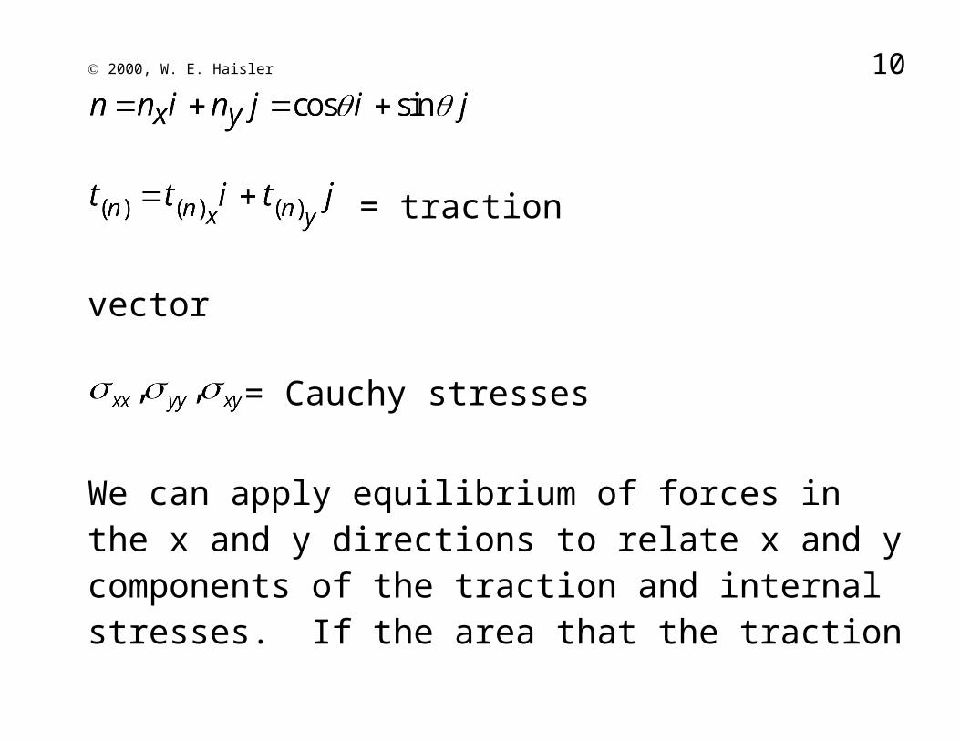
= traction vector
= Cauchy stresses

2000, W. E. Haisler 7
We can apply equilibrium of forces in the x and y directions to relate x and y components of the traction and internal stresses. If the area that the traction acts over is called A, then acts on area A cos and acts on area A sin .
or
And gives

2000, W. E. Haisler 8
These two equations can be written in matrix notation as
or
and in vector notation as
Recall that the usual dot product is applied to two vectors and results in a scalar. In the above matrix notation, the row vector (1x2) is dotted into each column vector (2x1) of the matrix (2x2) and results in a row vector (1x2). Thus, when we dot a vector into a tensor (square matrix), we obtain a vector.
The expression is a general result in 3-D which gives the projection of Cauchy stress tensor onto a plane whose unit normal is given by .

2000, W. E. Haisler 9
Consider a column loaded by a compressive pressure (traction) as shown below in left figure. Draw two diffeent freebodys as shown:
2000, W. E. Haisler 10
For freebody 1, where we cut the structure normal to the y axis, we obtain only the normal stress on the cutting plane.
For freebody 2, where we make a cut at some angle to the x-axis, we obtain a normal stress and a shear stress on the inclined cutting plane. For a given angle , we can obtain theses stresses by applying force equilibrium as was done in developing Cauchy's formula. Remember that equilibrium must be applied to forces, not stresses (force per area) since the areas may be different.

2000, W. E. Haisler 11Up to this point we have learned how to relate the Cauchy
stresses in a Cartesian coordinate system to tractions on an inclined plane with normal vector by use of Cauchy’s formula . We did this by cutting the cube with a cutting plane so as to form a free-body. In 2-D, we have

2000, W. E. Haisler 12
The components of are in x-y coordinates and are given by
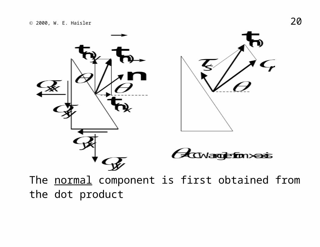
The traction vector on the inclined face, as given above, is written terms of its x and y components. It is much more informative and useful to write the traction vector in terms a normal component and a parallel (shear) component as shown below:
2000, W. E. Haisler 13
The normal component is first obtained from the dot product
or as a vector

2000, W. E. Haisler 14and the shear (parallel) component is obtained from vector addition
Now, lets carry out these vector operations to obtain and . The unit normal vector in 2-D (x-y) is given by
Cauchy's formula in vector notation
Normal component of traction

2000, W. E. Haisler 15
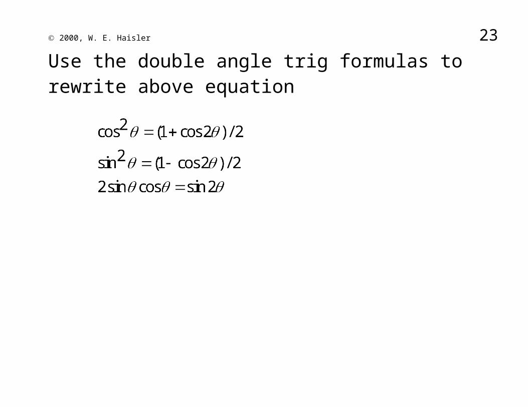
Use the double angle trig formulas to rewrite above equation
2000, W. E. Haisler 16
Thus, becomes
Shear component of traction
The shear component, , can be obtained from vector algebra, ie, or . Following the same procedure, we obtain

2000, W. E. Haisler 17
After squaring both sides of the and equations, adding the results to obtain one equation and using trig identities, we obtain the following
The above is similar to the equation of a circle of radius r located at x=a and y=b, ie,
(x-a)2 + (y-b)2 = r2

2000, W. E. Haisler 18
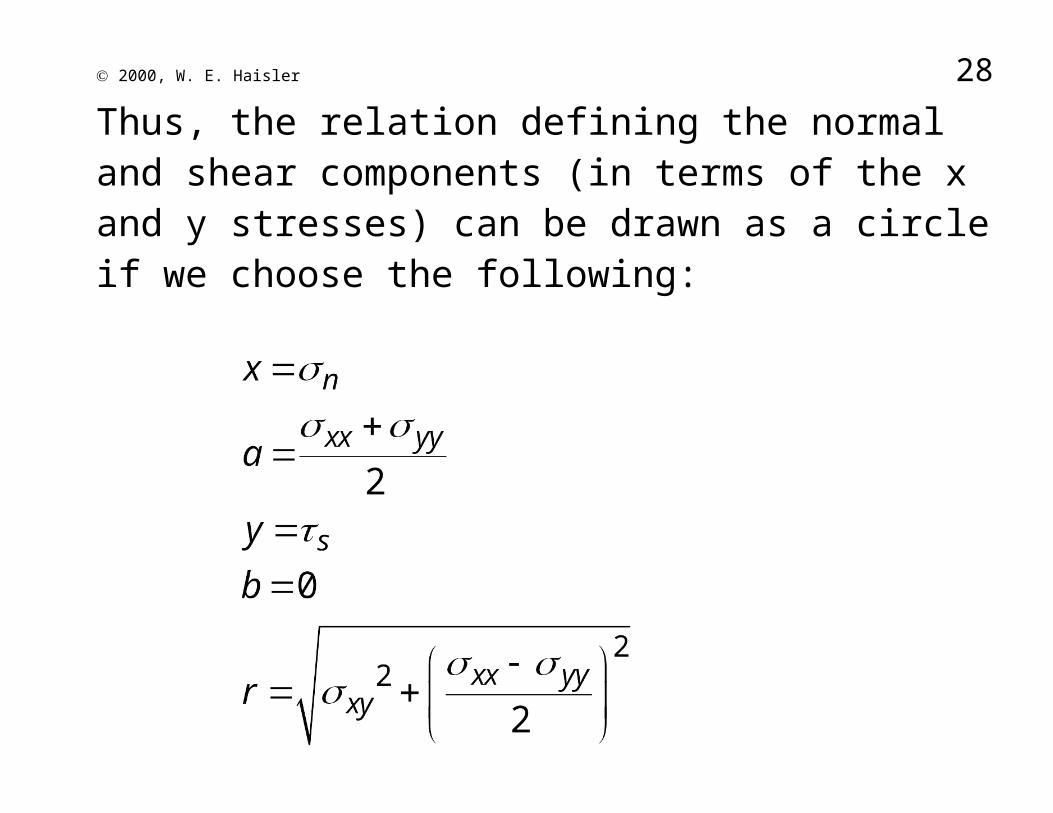
Thus, the relation defining the normal and shear components (in terms of the x and y stresses) can be drawn as a circle if we choose the following:

2000, W. E. Haisler 19
2000, W. E. Haisler 20
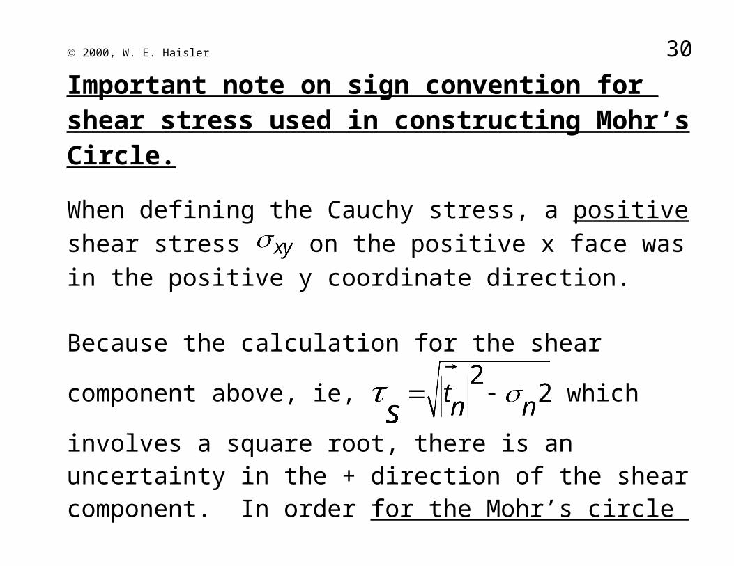
Important note on sign convention for shear stress used in constructing Mohr’s Circle.
When defining the Cauchy stress, a positive shear stress on the positive x face was in the positive y coordinate direction.
Because the calculation for the shear component above, ie,
which involves a square root, there is an
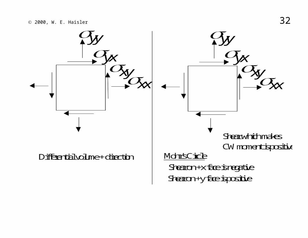
uncertainty in the + direction of the shear component. In order for the Mohr’s circle graphical representation to be used properly, we must adopt a sign convention:
Shear stresses on opposite faces that form a clockwise couple about the center are positive on the Mohr’s circle .

2000, W. E. Haisler 21
A positive (in the stress tensor) is plotted on Mohr's circle as negative for the x-face and positive for y-face.

2000, W. E. Haisler 22
Mohr’s Circle graphically represents the Cauchy formula for . It allows one to graphically determine the normal and shear stress on any plane relative to the x-y axes.
Its most important use is to determine the principal stresses (the maximum and minimum values of the normal stress, , where there is no shear stress), the maximum shear stress,
, and the orientation of the planes on which these occur.
2000, W. E. Haisler 23
Construction of Mohr’s Circle (method 1)
1. Locate center on axis at .
2. Draw circle with radius .
3. Locate the two points on circle with values of the stress components on the x-face and y-face. These two points lie on a diameter line of circle which passes through the center.
4. Determine max/min values of and and their plane orientation (angle from x or y face). Remember: angles on Mohr’s circle are twice the real world.

2000, W. E. Haisler 24
Construction of Mohr’s Circle (method 2)
1. Plot the values of normal and shear stress from the x-face ( and ) on the and axes. Observe Mohr’s circle assumption on
positive shear (shear is positive if moment due to shear is CW).
2. Plot the values of normal and shear stress from the y-face ( and ) on the and axes.
3. The above two points form the diameter of Mohr’s circle whose center is located where the diameter line intersects the axis.
4. Determine max/min values of and and their plane orientation (angle from x or y face). Remember: angles on Mohr’s circle are twice the real world.

2000, W. E. Haisler 25
Some reminders:1. For determining and from the defining equations, the
angle between the normal to any plane and the x-axis is defined positive in the CCW direction from the x-axis.
2. When plotting shear stresses on Mohr’s circle, a shear stress is considered positive if it produces a CW moment.
3. All angles on Mohr’s circle are twice the real world [the x- and y-face stresses are 90 in the x-y coordinate system, but 180 apart on Mohr’s circle (opposite ends of circle diameter)].
4. The planes of principal stress and maximum shear stress are 90 apart on Mohr’s circle and thus 45 apart in the real world!!!!
5. The angle defining the planes where the maximum values of and occur can also be obtained by calculus. If

2000, W. E. Haisler 26
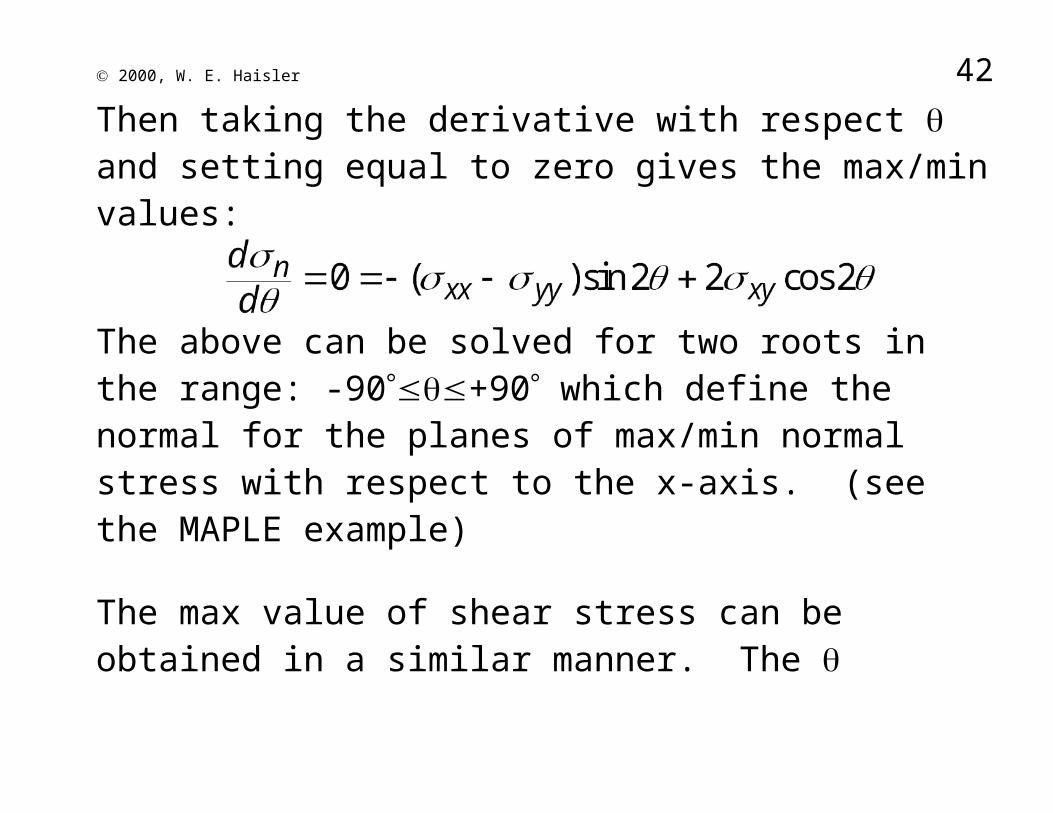
Then taking the derivative with respect and setting equal to zero gives the max/min values:
The above can be solved for two roots in the range: -90+90 which define the normal for the planes of max/min normal stress with respect to the x-axis. (see the MAPLE example)
The max value of shear stress can be obtained in a similar manner. The defining plane of max shear is always 45 from plane of max/min normal stress.

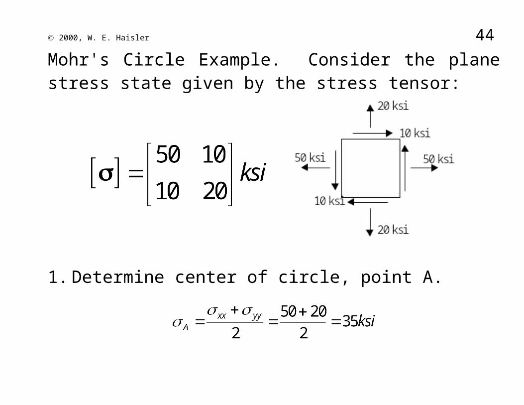
2000, W. E. Haisler 27Mohr's Circle Example. Consider the plane stress state given by the stress tensor:
1. Determine center of circle, point A.
2. Determine point B, x-face =(50,-10)
2000, W. E. Haisler 28
3. Determine point C, y-face =(20,+10)
4. Draw Mohr’s circle:

2000, W. E. Haisler 29
5. Compute principal stresses and max shear stress.
2000, W. E. Haisler 30
Note that we have two principal stresses: and . These are located 180 on Mohr's circle, but 90 in the real world. In relation to the stress transformation equations , in the normal stress in x'-axis direction (which is oriented at an angle to the x-axis) and is the normal stress in the y'-axis direction. The

2000, W. E. Haisler 31planes of maximum shear occur 45 (real world) from the planes of principal stress.Plot the principal stresses and max shear stresses on Mohr’s Circle:
2000, W. E. Haisler 32
6. Identify orientation of planes for principal stresses relative to x-face plane.

2000, W. E. Haisler 33
The plane for the second principal stress is CCW from x-face (real world). Note: In the above calculation, a formula was written down and used for . This is discouraged. It is far simpler (and usually less mistakes) to look at Mohr’s circle and apply trigonometry to calculate the angles.
7. Identify orientation of planes for maximum shear stress (bottom of circle) relative to x-face plane.

2000, W. E. Haisler 34
OR, plane of max shear stress (bottom of circle) is 45 CW in the real world from the principal stress plane with .Note:
Note that the plane of max shear stress will generally have non-zero normal stress! In this case, the plane of max shear stress has a normal stress .
8. Draw three free bodies: with the x-y stresses, with the principal stresses, and with the max shear stresses.
2000, W. E. Haisler 35

2000, W. E. Haisler 36Note the following: To obtain the orientation for principal stresses, the x-face has
been rotated 16.85 deg CCW in the real world (33.7 deg on Mohr’s circle).
To obtain the orientation for maximum shear stresses, the x-face has been rotated 28.15 deg CW in the real world (56.3 deg on Mohr’s circle), OR, equivalently a rotation of 45 deg CW in the real world from the principal stress plane.

2000, W. E. Haisler 37
Generalized Plane Stress
In the previous development of the Mohr’s Circle, we considered only the stresses in the x-y plane that resulted in two principal stresses and (remember, that principal stresses occur on planes where there is no shear stress). We can also use Mohr’s Circle for the case when the third plane (for example, the z plane) contains only a normal stress . The stress tensor is

2000, W. E. Haisler 38
Since there are no shear stresses on the z plane, is a principal stress, i.e., .
We note that in the x-y plane, Mohr’s circle is defined by a circle with coordinates of ( , 0) and ( , 0). Thus, the circle is (or can be) defined by the principal stresses. It follows that the Mohr’s circle for the x-z plane would also be formed the principal stresses in the x-z plane, in this case
and . Similarly, Mohr’s circle in the y-z plane is defined by and . We can draw all three of these circles on one diagram as shown below.

2000, W. E. Haisler 39

2000, W. E. Haisler 40Mohr's Circle Generalized Plane Stress Example. Consider the plane stress state given by the stress tensor:
Steps 1-7 will be identical to the previous example for the x-y plane (since both examples have exactly the same stress components in the x-y plane). Hence, for the x-y plane we obtain Mohr’s circle

2000, W. E. Haisler 41
To complete the solution we note that there are no shear stresses in the z plane and hence is automatically a principal stress. Thus, ksi. Adding the third principal stress to Mohr’s circle, we obtain:
2000, W. E. Haisler 42
Hence, the principal stresses are . The maximum shear stress is the radius of the largest Mohr’s

2000, W. E. Haisler 43
circle. Thus, when generalized
plane stress is considered.
2000, W. E. Haisler 44Some practice problems for Plane and Generalized Plane Stress:
1. (plane stress in x-y plane)
2. (plane stress in y-z plane)
3.4.5.6.7. (hydrostatic
compressive stress)
8. (generalized plane stress)
9. (generalized plane stress)
10.

2000, W. E. Haisler 45
Note on Three-Dimensional Stress Analysis
For a general stress tensor (3-D), it can be shown that the principal stresses are defined by the following eigenvalue problem:
or
The above yields a cubic equation in which can be solved for the three principal stress components. (See Sec. 2.2.7 of Introduction to Aerospace Structural Analysis by Allen and Haisler).