The Aurora COLA
47
The Aurora COLA April 15, 2020 Online public meeting
Transcript of The Aurora COLA

The Aurora COLAApril 15, 2020
Online public meeting
Introduction toAurora

Small inventory, small burnup, small power density• The Aurora produces 4 MWth, which is far smaller than any
commercial reactor in the U.S., and smaller even than some research reactors. • For comparison, the entire Aurora core produces about ¼ the power of one
fuel assembly at Diablo Canyon, and can dissipate it in about 100x the proportional mass of fuel, cladding, and structural material.
• The lower power of the Aurora also leads to low decay heat production. • 30 minutes after shutdown, the reactor is producing 65 kW of decay heat, • one day after shutdown the reactor is producing 21 kW of decay heat, and • 1 month after shutdown, the reactor is producing 7 kW of decay heat.
• The total burnup in 20 years does not exceed 1 at %.

Metal fuel
• Keeps fission products within the metal up to a certain burnup• Resistant to cracking or chipping - does not pulverize• Relative ease of manufacture, key properties insensitive to
manufacture method• High thermal conductivity and low specific heat
• Lower peak fuel temperature and stored energy• Easier to dissipate heat from the fuel
Simple structures, systems, and components (SSCs)• No pumps or valves, etc. in core or primary heat transport from core• Gravity-aided shutdown rods, no active control rods• Passive and very efficient heat transport from core – heat pipes
function as thermal superconductors • Equivalent thermal conductivity on the order of 10^6 W/m-K
• Many independent paths for passive heat transport from core
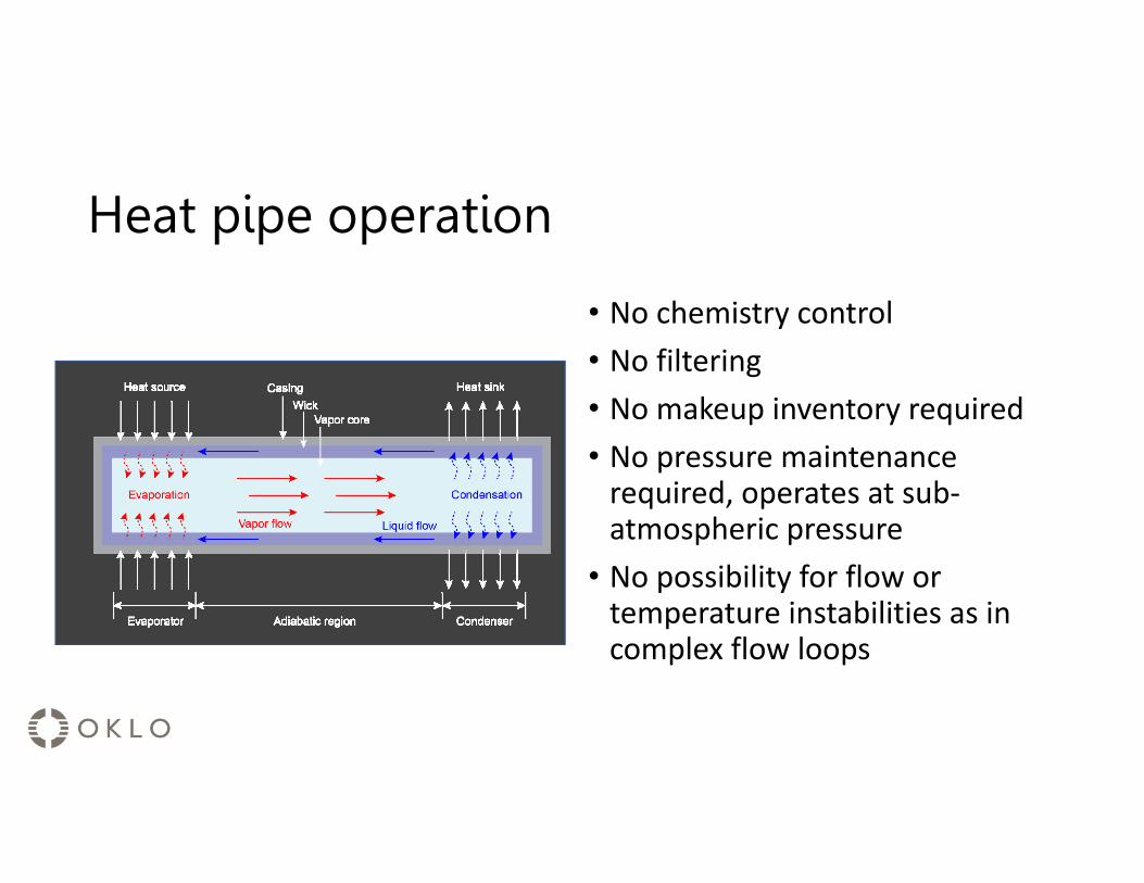
Heat pipe operation
• No chemistry control• No filtering• No makeup inventory required• No pressure maintenance
required, operates at sub-atmospheric pressure
• No possibility for flow or temperature instabilities as in complex flow loops
Other Aurora features
• Below-grade emplacement of the entire system offers simplicity, safety, and security benefits
• No offsite power dependence• No human action required for safety• No periodic refueling intervals

Safety case

Maximum credible accident• History of conceptual use for ~70 years• The worst credible accident(s) caused by any single event or failure• Broad review and analysis of events as categorized in NUREG 0800,
historical non-LWR event methodology, and events particular to the Aurora• Reliance on worst-case deterministic analysis removes uncertainties
introduced through reliance on risk analysis for a FOAK reactor, while Oklo can still show thorough analysis and incorporation of insights from advanced probabilistic risk analysis
• Further precedent for safety case and EPZ/site boundary for reactors of this size regulated by the NRC is shown through existing non-power reactors

Safety case• Because of the small size of the Aurora reactor, the maximum credible
accident is mitigated by the inherent features of the design• Small size, low power output, low power density, and low decay heat output • Low fuel burnup, small inventory of fuel, and limited available source term • Low decay heat term, removed by inherent and passive means • High thermal conductivity materials reduce temperature hot spots, and large
thermal mass provides capacity for heat dissipation • Inherent reactivity feedbacks ensure reactor power is controlled during overpower or
overtemperature events • High thermal conductivity materials reduce temperature hot spots, and large
thermal mass provides capacity for heat dissipation • Ambient pressure system removes sources of pressure and limits driving forces for
release

Application Structure
High level review
• Fundamentally, the Aurora-INL COLA structure is built from the regulations• This was developed in conversations with the NRC in early 2018 and
demonstrated in the DG-1353 structure in late 2018• The COLA articulates how the Aurora-INL meets the regulations for
COLs, in the approximate order as the regulations lay out requirements for application content in 10 CFR 52.77, 79, and 80.
• This final COLA structure has additionally employed unique methods to ensure safety metrics are tracked and upheld from design and analysis through programmatic controls which are described here.

Parts of the COLA
I. Company information and financial requirementsII. Final safety analysis reportIII. Environmental ReportIV. Technical SpecificationsV. Nonapplicabilities and requested exemptionsVI. Proposed license conditionsVII. Enclosures
Nomenclature of the COLA
• Parts of the COLA are designated with roman numerals and range from I-VII
• Parts are composed of chapters, which are designated with numbers• Often referred in shorthand, such as II.01, which means Part II,
Chapter 1

Combined license application requirements• The requirements for the items to be included in a COLA are included in the
following: • 10 CFR 52.77• 10 CFR 52.79• 10 CFR 52.80
• The Aurora COLA follows the structure of these regulations and not of any particular regulatory guidance document
• If a requirement (1) does not apply to the Aurora, or (2) if it does apply, but has a related requested exemption, it is a part of Part V, “Nonapplicabilitiesand requested exemptions”
• Slides at the end of this presentation describe each regulation and how it is met by the COLA

FSAR contents (summary of 10 CFR 52.79)
1 Site envelope and boundary 13 Organizational structure for operations2 Design and analysis of structures, systems, and components 14 Preoperational testing and initial operations3 Radioactive materials produced in operation 15 Operational plans4 Principal design criteria 16 Technical qualifications of the applicant5 Transient analysis 17 Training Program description6 Fire protection 18 Security plans7 Earthquake criteria 19 Incorporation of operational insights8 Unresolved and generic safety issues 20 Radiation Protection Program description9 Emergency planning 21 Fire Protection Program description
10 Emergency planning with state and local governments 22 Criticality accidents11 Prototype operational conditions 23 Fitness-for-Duty Program description12 Quality Assurance Program description 24 Probabilistic risk assessment summary
Operational plans
• Several FSAR chapters are only descriptions of operational plans• Examples: Emergency Plan, Physical Security Plan, Radiation
Protection Program• These plan documents themselves are included as enclosures to the
COLA, under Part VII, “Enclosures”

Safety case review• Small reactor – smaller heat output than the MIT research reactor, decay
heat at ~12h after shutdown on order of lawnmower• Small source term – small, low-enriched fuel inventory + few physically
possible ways to mobilize, very low burnup• Lower power density than the NGNP reactor case• The maximum credible accident (MCA) approach involves a systematic
analysis to identify the worst credible accident• This involved analysis of a broad range of events to analyze for doses.• No single event (common cause failures) or failure resulted in a release, no single
component deemed to be ”safety-related,” or otherwise classified.• All analysis involves conservatisms and assumptions, and certain performance of the
system is needed. This is where the development of design bases, commitments, programmatic controls, and principal design criteria ensure performance.

Methodology for the Aurora• Iterative and systematic process
• Systems are designed to high level safety goals• Their performance is evaluated under during normal
and off-normal (i.e., steady state and transient) operations through an analysis of many different event types:• Historical event types for non-LWRs• Event categorization in NUREG 0800• External hazards
• This performance is compared to insights gained from the PRA
• Subsequent slides explain the use of design bases, design commitments, design criteria, and programmatic controls to ensure as-designed, as-analyzed performance

Design bases: The characteristics of a system that ensure the safe operation of the reactor.
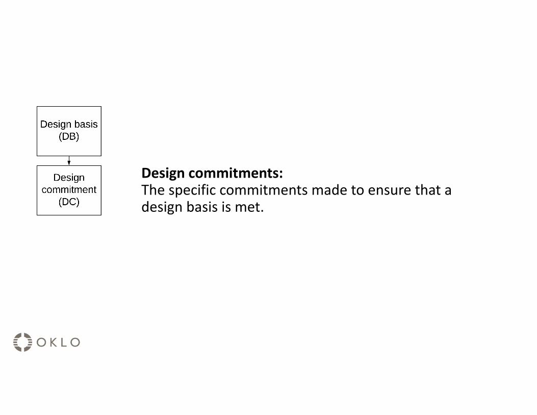
Design commitments:The specific commitments made to ensure that a design basis is met.
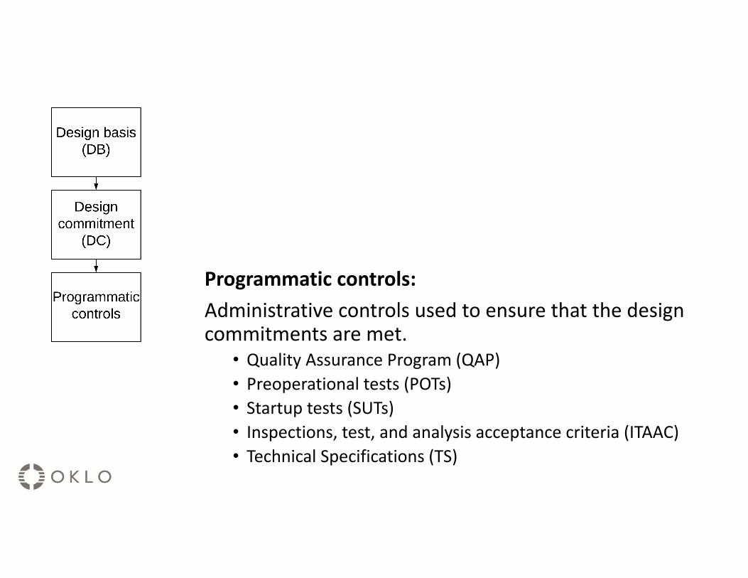
Programmatic controls:Administrative controls used to ensure that the design commitments are met.
• Quality Assurance Program (QAP)• Preoperational tests (POTs)• Startup tests (SUTs)• Inspections, test, and analysis acceptance criteria (ITAAC)• Technical Specifications (TS)

II.02 Design and Analysis of Structures, Systems, and
Components(Part II, “FSAR,” Chapter 2)
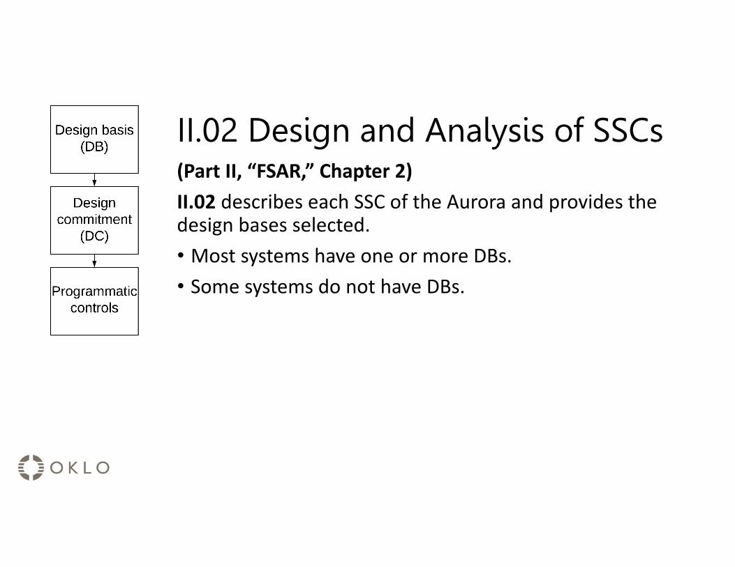
II.02 Design and Analysis of SSCs(Part II, “FSAR,” Chapter 2)II.02 describes each SSC of the Aurora and provides the design bases selected.• Most systems have one or more DBs.• Some systems do not have DBs.
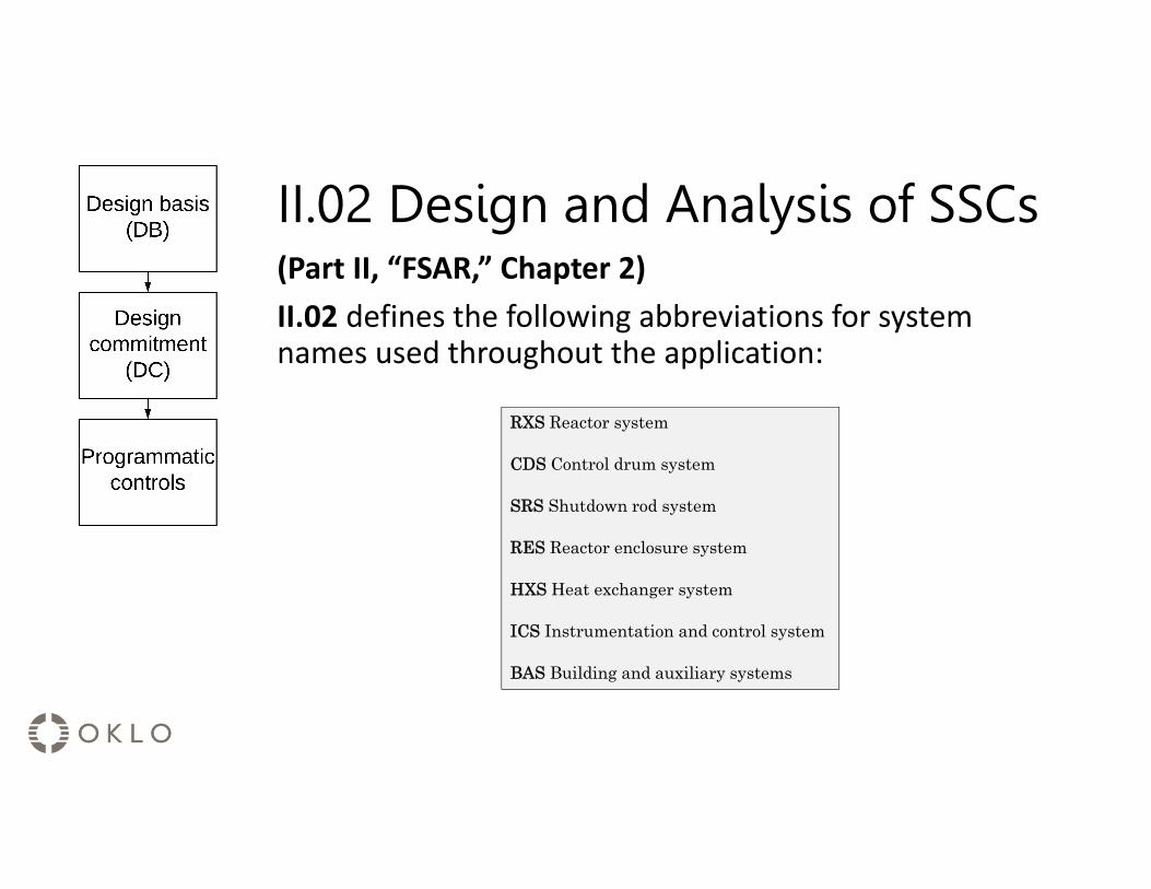
II.02 Design and Analysis of SSCs(Part II, “FSAR,” Chapter 2)II.02 defines the following abbreviations for system names used throughout the application:
RXS Reactor system
CDS Control drum system
SRS Shutdown rod system
RES Reactor enclosure system
HXS Heat exchanger system
ICS Instrumentation and control system
BAS Building and auxiliary systems

II.02 Design and Analysis of SSCs(Part II, “FSAR,” Chapter 2)II.02 uses these abbreviations to create unique codes for each DB, DC, and programmatic control, and summarizes each DB in a gray box.
Design basis:
DB.RXS.01 Specific characteristic of the reactor system
Design evaluation summary:
Summary of the analysis that shows the reactor system meets the DB...
Design commitments and programmatic controls:
DC.RXS.01A Specific commitment to ensure DB.RXS.01 is met
POT.RXS.01.A Preop. test used to verify DC.RXS.01.A
Or: SUT, ITAAC, TS, etc.

II.02 Design and Analysis of SSCs
• The systems focus of II.02 leads to the systems organization of the DBs• Ex: control drum system (CDS) and shutdown rod system (SRS)

II.05 Transient Analysis(Part II, “FSAR,” Chapter 5)

II.05 Transient Analysis(Part II, “FSAR,” Chapter 5)• II.05 is the chapter where transient analysis is
performed and described• This includes examination of many different event types and
analysis of applicable event types for the Aurora• Key modeling assumptions and inputs from chapter 5
lead directly from the DBs and their resulting DCs.• There is an iterative and integrated approach between
the transients and events analyzed and presented in II.05 and events described in other chapters such as seismic (II.07) and potential siting related events and considerations (II.01)

II.05 Transient Analysis(Part II, “FSAR,” Chapter 5)II.05 explicitly states key modeling assumptions, and summarizes accompanying DB and DC with a similar gray box.e.g.:An X second delay is assumed for shutdown rod insertion would look like:
DB.SRS.02 The shutdown rod system fully inserts the shutdown rods within a sufficient time after receiving a trip signal to prevent damage to the reactor.
DC.SRS.02.A The shutdown rod system fully inserts shutdown rods within 10 seconds of receiving a trip signal.
POT.SRS.02.A (see Chapter 14)
SUT.SRS.02.A
TS.LCO.01 (see Part IV)

Iterative Process• During the design process for the
Aurora an iterative process of design of systems (II.02) and safety analysis of those systems (II.05) was used.
• The design phase determined the required DBs, the safety analysis confirmed the sufficiency of the DBs, and through iteration a final set of DBs was selected.

Programmatic Controls

Programmatic ControlsThe Quality Assurance Plan, II.14 (Preoperational Testing and Initial Operations), IV (Technical Specifications), and VI.B (Proposed License Conditions, App. B: ITAAC) contain the programmatic controls that are used to verify design commitments are met. These include:
• QAPD (topical report submitted separately from COLA)• Preoperational tests (POTs, II.14)• Startup tests (SUTs, II.14)• Inspection, test, analysis and acceptance criteria (ITAAC, VI.B)• Technical specifications (TS, IV.)

Programmatic ControlsEach type of programmatic control helps assure DCs are met during a specific time period.

Programmatic ControlsII.14 (Preoperational Testing and Initial Operations) Describes the initial test program, which contains:• The preoperational tests (POTs) that must be completed
before fuel loading• The startup tests (SUTs) that must be completed after
fuel loading but before normal operations

Programmatic ControlsVI.B (Proposed License Conditions, App. B: ITAAC) Describes the ITAAC, which must be completed before fuel load.• Instead of taking individual ITAAC for every preoperational
test (POT)(in II.14), ITAAC are taken for verifying the successful completion of the POTs with the appropriate summary reports.
VI.B defines four ITAAC for the completion of POTs:• One ITAAC for testing of all reactor systems described in II.2• Three additional ITAAC for tests required by these programs:
• Emergency planning• Physical security• Radiation protection

Programmatic ControlsPart IV provides the Technical Specifications (TS) for the Aurora. The TS describe the programmatic controls that ensure the DCs are met on an ongoing basis.

Principal Design Criteria

II.04 Principal Design Criteria(Part II, “FSAR,” Chapter 4)The PDC of the Aurora are derived from Fundamental Safety Functions and other regulatory requirements. The design criteria orfundamental safety function focus of II.04 allows for another method to derive and organize the DBs described in II.02 and confirmed to be sufficient by the safety analysis in II.05: by function rather than by system (as in II.02 and II.05).

SummaryFSAR, description of SSCs (II.02) describes each system and provides the DBs and DCs from a system-up perspective
FSAR, transient analysis (II.05) describes assumptions and key parameters in analysis and confirms the sufficiency of the DBs and DCs in ensuring safety
FSAR, principal design criteria (II.04) are derived from fundamental safety functions and other regulatory requirements, and are another functional method for grouping DBs from PDC-down, separately from the system-up method.
The design process between II.02 and II.05 is iterative with insight from risk and external hazards, and PDC allow for a functional derivation of DBs.
QAPD, ITA (II.14), TS (IV), and ITAAC (VI.B) provide the programmatic controls that ensure the DBs and DCs are met starting from manufacturing, initial testing, and on an ongoing basis.

Background slides

10 CFR 50.77 – (i.e., 10 CFR 50.33)Section Short description Location in COLA50.33(a) Name I.0150.33(b) Address I.0150.33(c) Description of business I.0150.33(d) Business details I.0150.33(e) Class of license I.0250.33(f) Financial qualification I.0350.33(g) Emergency planning governments I.0450.33(h) Construction or alteration V.0350.33(i) Generation and distribution of electric energy V.0350.33(j) Restricted Data or defense information V.0350.33(k) Decommissioning I.05

10 CFR 52.79 (part 1/4)Section Short description Location in COLA52.79(a)(1) Site envelope and boundary II.0152.79(a)(2) Design and analysis of structures, systems, and
componentsII.02
52.79(a)(3) Radioactive materials produced in operation II.0352.79(a)(4) Principal design criteria II.0452.79(a)(5) Transient analysis II.0552.79(a)(6) Fire protection II.0652.79(a)(7) Pressurized thermal shock V.0352.79(a)(8) Combustible gas control V.0352.79(a)(9) Station blackout V.0352.79(a)(10) Environmental qualification of electric equipment V.0352.79(a)(11) Codes and standards V.0352.79(a)(12) Primary containment leakage rate testing program V.03

10 CFR 52.79 (part 2/4)Section Short description Location in COLA52.79(a)(13) Reactor vessel material surveillance program V.03
52.79(a)(14) Operator training program V.0452.79(a)(15) Maintenance rule V.03
52.79(a)(16) Effluent monitoring and sampling V.03
52.79(a)(17) Three Mile Island requirements V.03
52.79(a)(18) Risk-informed treatment of SSCs V.03
52.79(a)(19) Earthquake criteria II.0752.79(a)(20) Unresolved and generic safety issues II.0852.79(a)(21) Emergency planning II.0952.79(a)(22) Emergency planning with state and local governments II.1752.79(a)(23) Reserved V.03
52.79(a)(24) Prototype operational conditions II.11
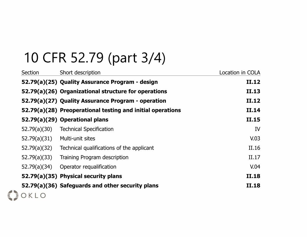
10 CFR 52.79 (part 3/4)Section Short description Location in COLA52.79(a)(25) Quality Assurance Program - design II.1252.79(a)(26) Organizational structure for operations II.1352.79(a)(27) Quality Assurance Program - operation II.1252.79(a)(28) Preoperational testing and initial operations II.1452.79(a)(29) Operational plans II.1552.79(a)(30) Technical Specification IV52.79(a)(31) Multi-unit sites V.0352.79(a)(32) Technical qualifications of the applicant II.1652.79(a)(33) Training Program description II.1752.79(a)(34) Operator requalification V.0452.79(a)(35) Physical security plans II.1852.79(a)(36) Safeguards and other security plans II.18
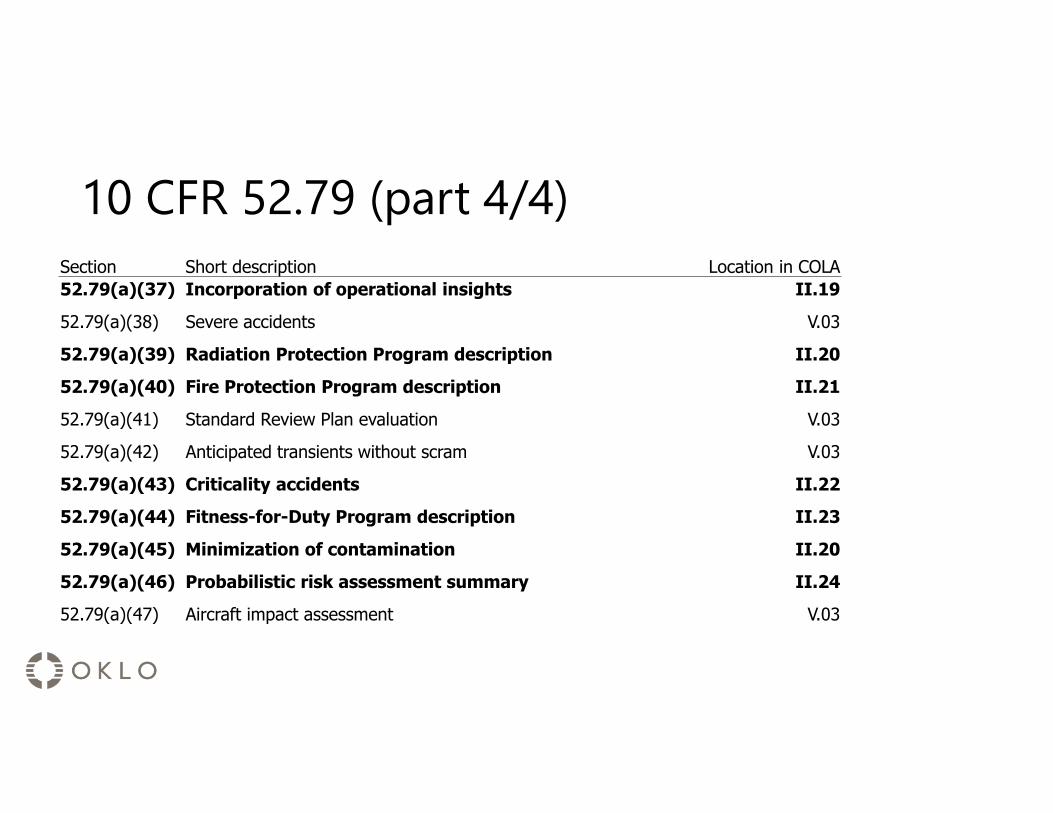
10 CFR 52.79 (part 4/4)Section Short description Location in COLA52.79(a)(37) Incorporation of operational insights II.1952.79(a)(38) Severe accidents V.03
52.79(a)(39) Radiation Protection Program description II.2052.79(a)(40) Fire Protection Program description II.2152.79(a)(41) Standard Review Plan evaluation V.03
52.79(a)(42) Anticipated transients without scram V.03
52.79(a)(43) Criticality accidents II.2252.79(a)(44) Fitness-for-Duty Program description II.2352.79(a)(45) Minimization of contamination II.2052.79(a)(46) Probabilistic risk assessment summary II.2452.79(a)(47) Aircraft impact assessment V.03

10 CFR 52.80Section Short description Location in COLA52.80(a) Inspections, tests, analyses, and acceptance criteria VI52.80(b) Environmental report III52.80(c) Limited work authorization V.0352.80(d) Mitigation of beyond design basis events V.03