The ATLAS Beam Conditions Monitor
29
The ATLAS Beam Conditions Monitor Marko Mikuž University of Ljubljana & Jožef Stefan Institute IEEE NSS’07 N31-7 Hawaii, October 31, 2007
-
Upload
coby-riley -
Category
Documents
-
view
23 -
download
0
description
The ATLAS Beam Conditions Monitor. Marko Miku ž University of Ljubljana & Jo ž ef Stefan Institute IEEE NSS ’07 N31-7 Hawaii, October 31, 2007. The ATLAS BCM collaboration. CERN D. Dabos, H. Pernegger, P. Weilhammer Fotec & Univ. Wiener Neustadt E. Griesmayer, H. Frais-Kölbl, M. Niegl - PowerPoint PPT Presentation
Transcript of The ATLAS Beam Conditions Monitor

The ATLAS Beam Conditions Monitor
Marko MikužUniversity of Ljubljana & Jožef Stefan Institute
IEEE NSS’07 N31-7
Hawaii, October 31, 2007

NSS’07, Hawaii, Oct 31, 2007 ATLAS BCM (M.Mikuž, Ljubljana) 2
The ATLAS BCM collaboration
• CERN D. Dabos, H. Pernegger, P. Weilhammer
• Fotec & Univ. Wiener Neustadt E. Griesmayer, H. Frais-Kölbl, M. Niegl
• JSI & Univ. Ljubljana V. Cindro, I. Dolenc, A. Gorišek, G.Kramberger, B. Maček,
I. Mandić, E. Margan, M. Zavrtanik, M. Mikuž
• OSU, Columbus H. Kagan, S. Smith
• Univ. Toronto M. Cadabeschi, D. Tardif, W. Trischuk
~20 people from 5 institutes

NSS’07, Hawaii, Oct 31, 2007 ATLAS BCM (M.Mikuž, Ljubljana) 3
Aim of the ATLAS BCM
• Goal of the BCM detector system inside the ATLAS Inner Detector:
Monitor instantaneous background rate and collision rate during normal running
• Measure background rate close to vertex• Compare to rate of collisions and provide basic bunch-by-bunch
luminosity measurement
Protection in case of larger beam losses• Detect early signs of beam instabilities (e.g. wrong magnet settings,
trips,…)• Issue warning and alarm signals for equipment protection• Input to ATLAS Detector Safety system and LHC beam abort

NSS’07, Hawaii, Oct 31, 2007 ATLAS BCM (M.Mikuž, Ljubljana) 4
Timing of background vs. interactions• Distinguish collisions from background through time-of-flight measurement with detectors at either side of
the IP Is measured for every bunch crossing (25ns) Requires fast and radiation hard detector + electronics ( rise time ~ 1ns, pulse width ~ 3ns, baseline restoration < 10ns) Out of collision time hits signatures of beam anomalies
Time difference
Interactions: t = 0, 25, … ns Upstream background: t = 2z/c = 12ns
BCM Side A - Side C

NSS’07, Hawaii, Oct 31, 2007 ATLAS BCM (M.Mikuž, Ljubljana) 5
The Beam Conditions Monitor
• 4 BCM stations on each side of the Pixel detector Mounted on Pixel support structure at z
= +/- 183.8 cm and r = 5.5 cm Each station: 1 cm2 detector element +
front-end analogue readout
183cm
38 cm

NSS’07, Hawaii, Oct 31, 2007 ATLAS BCM (M.Mikuž, Ljubljana) 6
The BCM is installed in ATLAS
• BCM installed on Pixel detector, lowered into ATLAS pit in June 2007
NSS’07, Hawaii, Oct 31, 2007 ATLAS BCM (M.Mikuž, Ljubljana) 7
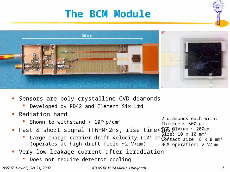
The BCM Module
• Sensors are poly-crystalline CVD diamonds Developed by RD42 and Element Six Ltd
• Radiation hard Shown to withstand > 1015 p/cm2
• Fast & short signal (FWHM~2ns, rise time<1ns) Large charge carrier drift velocity (107 cm/s)
(operates at high drift field ~2 V/m)
• Very low leakage current after irradiation Does not require detector cooling
2 diamonds each with:Thickness 500 mCCD @1V/m ~ 200mSize: 10 x 10 mm2
Contact size: 8 x 8 mm2
BCM operation: 2 V/m
NSS’07, Hawaii, Oct 31, 2007 ATLAS BCM (M.Mikuž, Ljubljana) 8
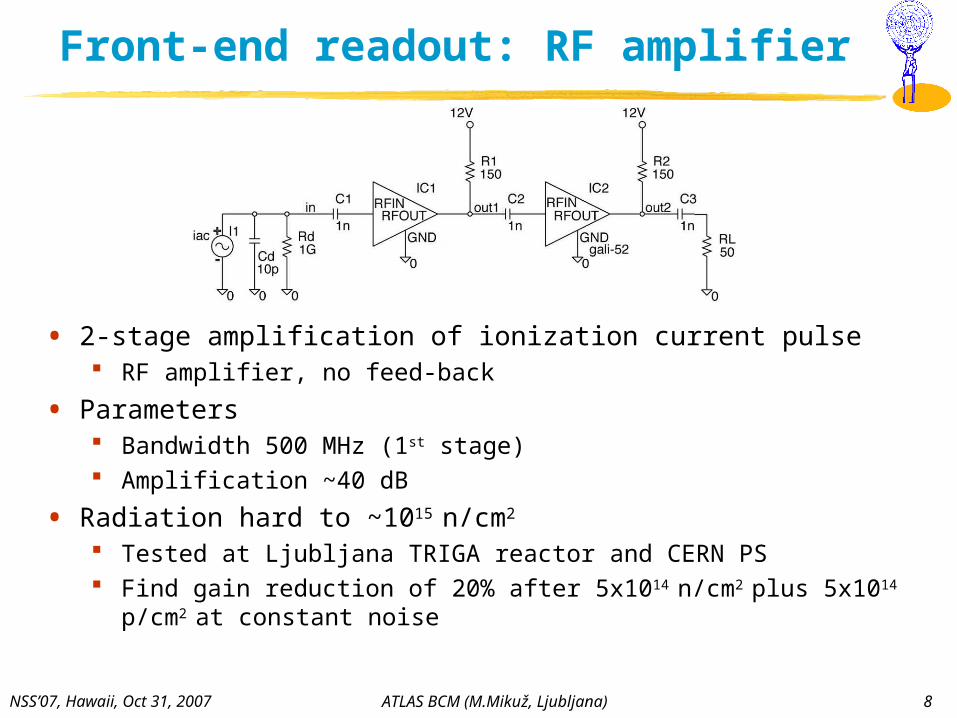
Front-end readout: RF amplifier
• 2-stage amplification of ionization current pulse RF amplifier, no feed-back
• Parameters Bandwidth 500 MHz (1st stage) Amplification ~40 dB
• Radiation hard to ~1015 n/cm2
Tested at Ljubljana TRIGA reactor and CERN PS Find gain reduction of 20% after 5x10¹⁴ n/cm2 plus 5x10¹⁴ p/cm2 at constant
noise

NSS’07, Hawaii, Oct 31, 2007 ATLAS BCM (M.Mikuž, Ljubljana) 9
BCM system overview
Inside Pixel Package At PP2 (~1st muon chamber) Counting room USA15
~30 Mraddetector
~1 kradTOT “digitization”

NSS’07, Hawaii, Oct 31, 2007 ATLAS BCM (M.Mikuž, Ljubljana) 10
Functional tests of BCM chain
• BCM modules and performance of the signal processing chain have been tested in several lab tests and test beams
• We currently use beam tests to commission the readout electronics using three spare modules
• The next slides will show an overview of the tests done: Module tests during production Analogue signal response during beam tests Performance after analogue-to-digital conversion and optical link Efficiency & Noise Timing resolution

NSS’07, Hawaii, Oct 31, 2007 ATLAS BCM (M.Mikuž, Ljubljana) 11
Module tests• Diamonds
IV curve & CCD measurements before assembly to modules
• Use 90Sr source test setup to characterize each module Measure signal distribution and noise in HV scan from -1000V to +1000V Done before and after burn-in (80°C@12hrs) and thermal cycling (10 cycles -20 to
+40°C) while modules are operated
• Measure on modules a most probable SNR = (7.3 ± 0.56) :1 for 90° impact Meets our requirement of 10:1 in final configuration at 45° ( x √2)
Smp ~ 2.7mVNoise rms~330 V
200 MHz BWL

NSS’07, Hawaii, Oct 31, 2007 ATLAS BCM (M.Mikuž, Ljubljana) 12
Test beam (CERN SPS)
• Test BCM modules in high energy pion beam at CERN SPS
• Goal: Evaluate analogue signals Test NINO time-over-threshold
(TOT) conversion and opto-link Measure efficiency, noise rate and
timing resolution Test V1.0 of FPGA readout board
• Setup: Telescope with 5 scintillators and
2x2 mm2 trigger area, BCM modules moved across beam
BCM stations connected via 16 m coax cable to Ortec 300 MHz amplifier for analogue measurements and VME 2 Gs/s ADC
BCM stations connected via 16 m coaxial cable to NINO board + opto transmitter + fibre + opto receiver going to VME readout and FPGA readout
NSS’07, Hawaii, Oct 31, 2007 ATLAS BCM (M.Mikuž, Ljubljana) 13
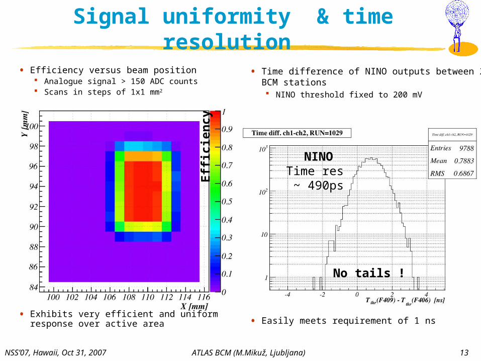
Signal uniformity & time resolution
• Efficiency versus beam position Analogue signal > 150 ADC counts Scans in steps of 1x1 mm2
• Exhibits very efficient and uniform response over active area
• Time difference of NINO outputs between 2 BCM stations NINO threshold fixed to 200 mV
• Easily meets requirement of 1 ns
NINOTime res ~ 490ps
No tails !
Effi
cie
ncy
NSS’07, Hawaii, Oct 31, 2007 ATLAS BCM (M.Mikuž, Ljubljana) 14
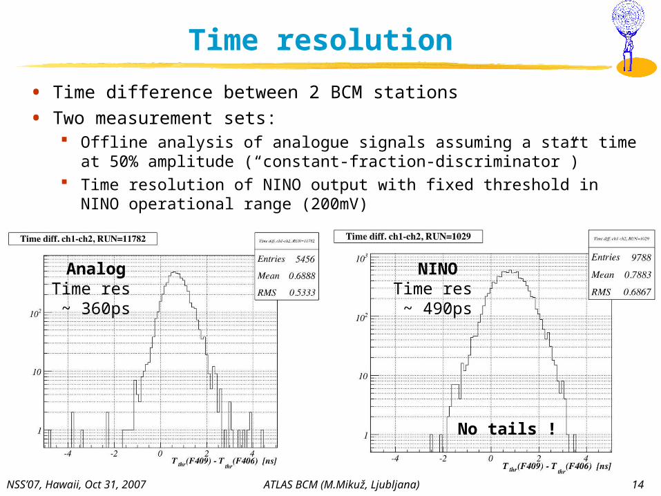
Time resolution
• Time difference between 2 BCM stations
• Two measurement sets: Offline analysis of analogue signals assuming a start time at 50% amplitude
(“constant-fraction-discriminator”) Time resolution of NINO output with fixed threshold in NINO operational
range (200mV)
AnalogTime res ~ 360ps
NINOTime res ~ 490ps
No tails !
NSS’07, Hawaii, Oct 31, 2007 ATLAS BCM (M.Mikuž, Ljubljana) 15
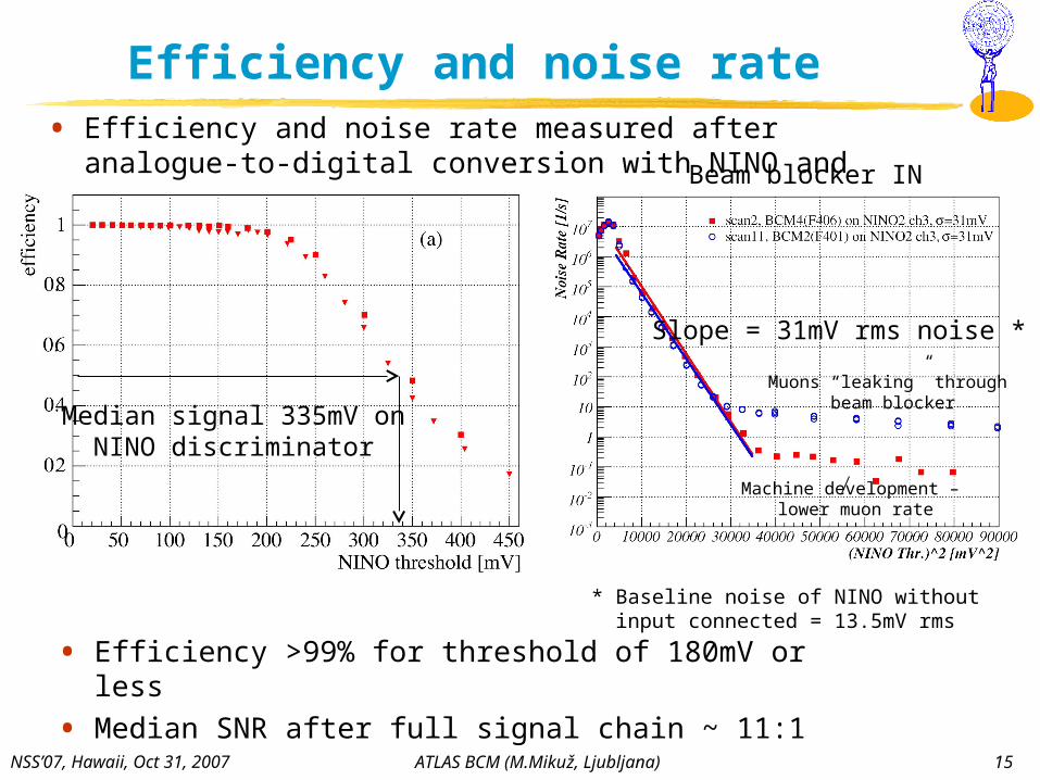
Efficiency and noise rate • Efficiency and noise rate measured after analogue-to-digital
conversion with NINO and optical link
Median signal 335mV onNINO discriminator
Slope = 31mV rms noise *
* Baseline noise of NINO without input connected = 13.5mV rms
• Efficiency >99% for threshold of 180mV or less
• Median SNR after full signal chain ~ 11:1
Beam blocker IN
Muons “leaking” through beam blocker
Machine development – lower muon rate

NSS’07, Hawaii, Oct 31, 2007 ATLAS BCM (M.Mikuž, Ljubljana) 16
Operation in ATLAS
• For operation want to maximize efficiency at minimal number of noise hits per LHC BX (25 ns)
• Threshold optimized with efficiency versus noise occupancy per module and BX: Horizontal axis is calculated from fit to previous noise vs threshold plot
e.g. 180 mV threshold:
Efficiency is 99% atnoise occupancy of 3 x 10⁻⁸ /module/BX
At low luminosity (5x1032 cm-2s-1) expect ~13% of BX’s have Side A-C coincidence

NSS’07, Hawaii, Oct 31, 2007 ATLAS BCM (M.Mikuž, Ljubljana) 17
Radiation test of complete module
• Radiation hardness of sensors, electronics and components verified separately up to level of 1015 cm-2 (30 MRad)
• Want to assess performance of complete module
• Irradiation/test of one module Test in beam – June 07 Irradiate to 1014 p/cm2 – July 07 Test in beam – August 07 Irradiate to 3x10¹⁴ p/cm2 – September 07 Test in beam – now Irradiate to 1015 p/cm2 – Spring 08 Test in beam – Summer 08
non-irradiated
1014 p/cm2
• ~20 % of signal loss observed in test beam after 1014 p/cm2
Diamonds not properly pumped – need to cover complete sensor
Loss consistent with that of samples irradiated to same fluence with neutrons – see talk N44-5 tomorrow
Expect complete signal recovery after pumping Tests with module irradiated to 3x10¹⁴ p/cm2 ongoing
NSS’07, Hawaii, Oct 31, 2007 ATLAS BCM (M.Mikuž, Ljubljana) 18
Summary
• ATLAS BCM will monitor beam conditions close to the IP in ATLAS using a time-of-flight measurement
• Based on pCVD diamonds readout by fast RF amplifiers to achieve very fast signal response and required radiation hardness Rise time 1.3ns & ~2ns FWHM pulse width
• We have tested the full set of BCM modules in beam tests demonstrating the required performance Efficiency of ~99% at operational threshold with noise occupancy
/module/BX <10-7
Time resolution ~500ps
• All BCM modules were installed in ATLAS together with the ATLAS Pixel detector in June 2007

NSS’07, Hawaii, Oct 31, 2007 ATLAS BCM (M.Mikuž, Ljubljana) 19
Backup slides …
NSS’07, Hawaii, Oct 31, 2007 ATLAS BCM (M.Mikuž, Ljubljana) 20
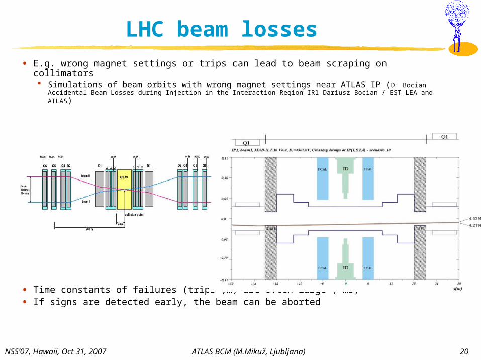
LHC beam losses
• E.g. wrong magnet settings or trips can lead to beam scraping on collimators Simulations of beam orbits with wrong magnet settings near ATLAS IP (D. Bocian
Accidental Beam Losses during Injection in the Interaction Region IR1 Dariusz Bocian / EST-LEA and ATLAS)
• Time constants of failures (trips ,…) are often large (~ms)
• If signs are detected early, the beam can be aborted

NSS’07, Hawaii, Oct 31, 2007 ATLAS BCM (M.Mikuž, Ljubljana) 21
Signal optimization• Step 1: 2 Diamonds read out in parallel increase signal by factor 2, noise
increases only by ~30%
• Step 2: Place at 45 degrees -> 2 signal increase, no noise increase
• Step 3: Adding ~200-300MHz BWL on NINO input improves SNR by 30% (timing resolution worsens by ~ 10%)
• Step 4: operate at 2V/m instead of 1V/m -> increases signal by up to 50%
amplitude noise
SNR
no BWL
200MHz BWL
RMS=0.66mV
RMS=0.33mV
MP=3.7mV
MP=2.5mV

NSS’07, Hawaii, Oct 31, 2007 ATLAS BCM (M.Mikuž, Ljubljana) 22
Analogue response in test beam
• Single event and signal distribution
• <Signal rise time>=1.3 ns and <FWHM pulse width> = 2.1 ns
• Signal and noise well separated

NSS’07, Hawaii, Oct 31, 2007 ATLAS BCM (M.Mikuž, Ljubljana) 23
5 x 1032
2.8 x 1034
1 x 1034
Number of BCM hits & coincidences
• Number of BCM station hits/BCO At low luminosity
expect ~ 50% of BCO have >= 1 hit
• Coincidences Plots as # Side A * #
Side C At low luminosity
expect ~13% of BCM have a coincidence
No timing cut
NSS’07, Hawaii, Oct 31, 2007 ATLAS BCM (M.Mikuž, Ljubljana) 24
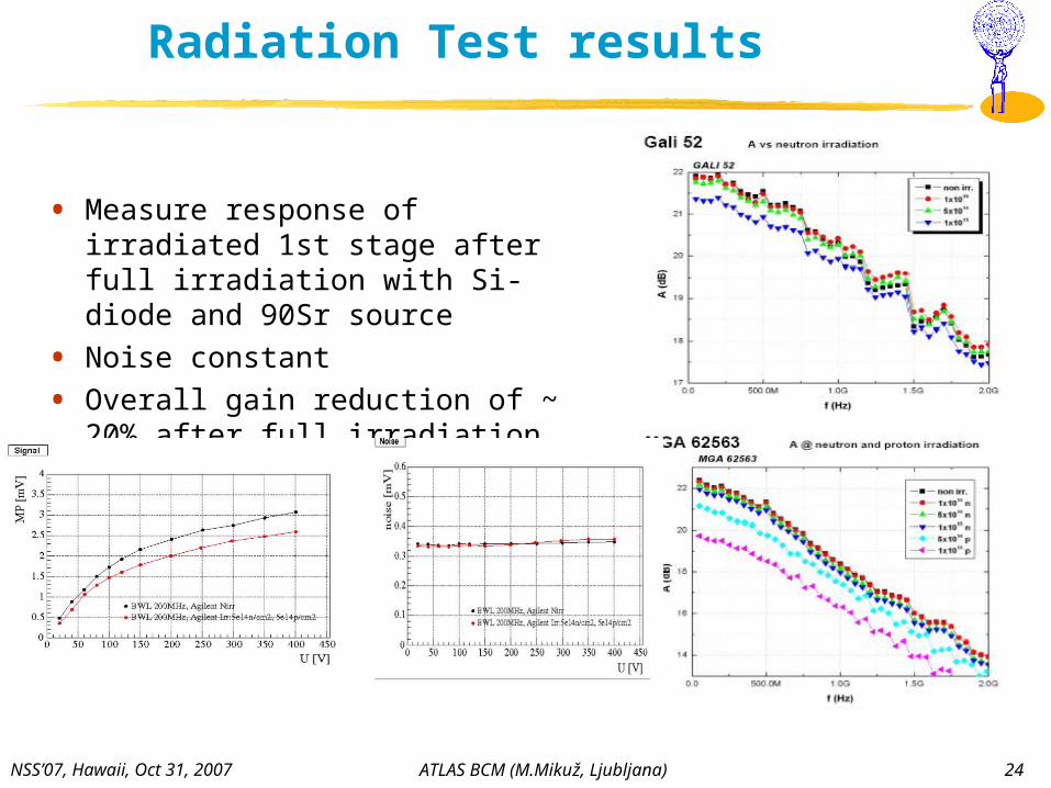
Radiation Test results
• Measure response of irradiated 1st stage after full irradiation with Si-diode and 90Sr source
• Noise constant
• Overall gain reduction of ~ 20% after full irradiation

NSS’07, Hawaii, Oct 31, 2007 ATLAS BCM (M.Mikuž, Ljubljana) 25
LHC Beam loss scenario
• Simulation by CMS: single proton lost on collimator (“TAS”)
(dose [Gy])
(M. Huhtinen, LHC Machine Protection WG, Oct. 2003)
~ MIPs/cm2 per proton

NSS’07, Hawaii, Oct 31, 2007 ATLAS BCM (M.Mikuž, Ljubljana) 26
Passive signal summation
• Increase signal by using 2 diamonds acting as one current source (“Double diamond assembly”) 2 independent current signals summed at input
signal
HV drift voltage
NSS’07, Hawaii, Oct 31, 2007 ATLAS BCM (M.Mikuž, Ljubljana) 27
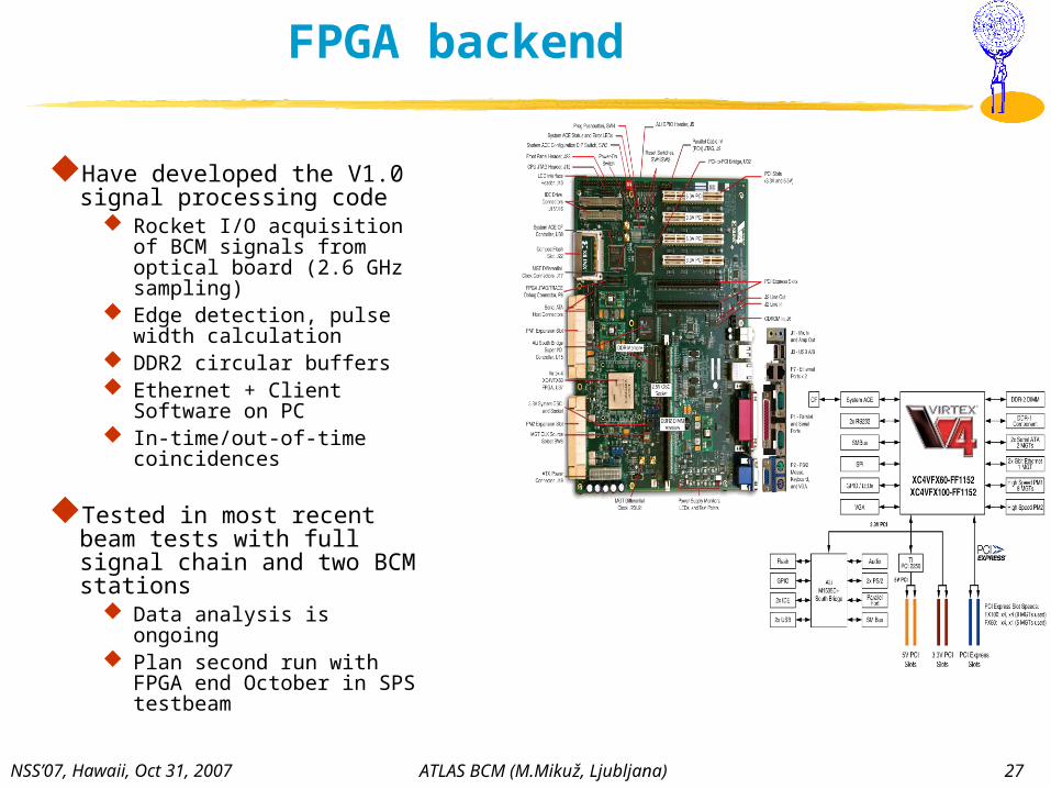
FPGA backend
Have developed the V1.0 signal processing code
Rocket I/O acquisition of BCM signals from optical board (2.6 GHz sampling)
Edge detection, pulse width calculation
DDR2 circular buffers Ethernet + Client Software on
PC In-time/out-of-time
coincidences
Tested in most recent beam tests with full signal chain and two BCM stations
Data analysis is ongoing Plan second run with FPGA
end October in SPS testbeam

NSS’07, Hawaii, Oct 31, 2007 ATLAS BCM (M.Mikuž, Ljubljana) 28
BCM simulations
• Simulations in full ATHENA framework
• Average number of tracks in BCM diamonds per p-p collision: 0.375
• Surprise: half of events from decays and scattering in material
• Studies of coincidences to establish FPGA algorithms ongoing
BCM
Pixels
Beam pipeDecays

NSS’07, Hawaii, Oct 31, 2007 ATLAS BCM (M.Mikuž, Ljubljana) 29
BCM simulations – movement of vertex
• Explored sensitivity of BCM rates to vertex displacements• Vertex displaced to z = +10 cm• Surprise: more BCM hits on side C – secondaries dominate• dPA/dz = (-0.11 ± 0.05) m-1, effect at % level (• dPA/dz = +0.12 m-1 for primaries only
Vertex at z=0 Vertex at z=+10
More material towards Side C