The Art and Science of Sound RCC In-Wall Subwoofer...
12
2231 Meridian Blvd., Suite #1 ∙ Minden, NV 89423 ∙ www.artisonusa.com The Art and Science of Sound RCC In-Wall Subwoofer Design “The Science of Sound is easy. Mostly because the engineering principles that govern how audio is reproduced and then perceived by the human brain have been studied and applied to speakers for many years. Such factors as distortion, power response, phase, etc. are well understood and their effects have been used to improve the design and manufacture of Consumer Electronics products long before I was a part of this industry. The Art of Sound is another matter. There are always new products that come to market which demonstrate ways in which consumers can be attracted to a new and different concept. It is the proper application of known scientific data and invention to new products that is the Art of Sound.” Cary Christie President & CEO, ARTISON Artison’s Front Channel LCR DM’s and SoundBars integrate into the television monitor and visually disappear, our surrounds are inconspicuous or can be sunk into a wall or ceiling and also disappear. The only remaining visible culprit to the perfect audio system was the subwoofer. It would be a shame to leave a conspicuous box sitting in the room when you can so easily make it go away. We decided that if we were to make a contemporary subwoofer it should be able to hide in plain sight. That meant that it had to go into a wall, floor, or ceiling cavity or be a very small and unobtrusive design. Again, we started with a clean sheet of paper and created a product definition. Ours went something like this: • The kinetic energy generated by the movement of the drivers must be isolated so as not to create vibrations in the wall • The system should easily retrofit into an existing structure without having to rebuild the room • Should play at realistic levels down to 20 Hz • The drivers should be well controlled and reproduce the electrical signal perfectly • The components of the subwoofer that are visible should be small and unassuming when installed
Transcript of The Art and Science of Sound RCC In-Wall Subwoofer...

2231 Meridian Blvd., Suite #1 ∙ Minden, NV 89423 ∙ www.artisonusa.com
The Art and Science of Sound RCC In-Wall Subwoofer Design
“The Science of Sound is easy. Mostly because the engineering principles that govern how audio is reproduced
and then perceived by the human brain have been studied and applied to speakers for many years. Such
factors as distortion, power response, phase, etc. are well understood and their effects have been used to
improve the design and manufacture of Consumer Electronics products long before I was a part of this industry.
The Art of Sound is another matter. There are always new products that come to market which demonstrate ways
in which consumers can be attracted to a new and different concept. It is the proper application of known
scientific data and invention to new products that is the Art of Sound.”
Cary Christie President & CEO, ARTISON
Artison’s Front Channel LCR DM’s and SoundBars integrate into the television monitor and
visually disappear, our surrounds are inconspicuous or can be sunk into a wall or ceiling and
also disappear. The only remaining visible culprit to the perfect audio system was the
subwoofer. It would be a shame to leave a conspicuous box sitting in the room when you can
so easily make it go away. We decided that if we were to make a contemporary subwoofer it
should be able to hide in plain sight. That meant that it had to go into a wall, floor, or ceiling
cavity or be a very small and unobtrusive design. Again, we started with a clean sheet of
paper and created a product definition. Ours went something like this:
• The kinetic energy generated by the movement of the drivers must be isolated so
as not to create vibrations in the wall
• The system should easily retrofit into an existing structure without having to rebuild
the room
• Should play at realistic levels down to 20 Hz
• The drivers should be well controlled and reproduce the electrical signal perfectly
• The components of the subwoofer that are visible should be small and
unassuming when installed
2231 Meridian Blvd., Suite #1 ∙ Minden, NV 89423 ∙ www.artisonusa.com
A decade ago we made a subwoofer called the RCC-210 which was quite a good performer.
It was unique in what we referred to as its reactance canceling configuration. It played loud
and was considered by all that reviewed it as a very good subwoofer. One of the real
advantages of the RCC-210’s design was the use of dual woofers rigidly connected to each
other via the cabinet in a way that used the reactive forces generated by the woofer
movement to cancel the same reactive forces in the opposing driver. With this type of
design the drivers are wired in phase and the cone motion in one driver of the pair is a mirror
image of the complementary driver. The result was a perfectly balanced subwoofer that
converted all of the amplifier’s energy into a movement of air without wasting any of the
power trying to move the cabinet.
Reactance Cancelling Configuration
Newton’s Third Law of Motion simply is that for every action there is an equal and opposite
reaction. Think of the explosion of a cannon and the recoil of the device, or conversely a
bouncing a ball on the ground. The action, or force, is met by an equal and opposite
reaction, or reactance force.
In subwoofer design this law is illustrated by the moving woofer cone creating a sound wave
in one direction but also an equal amount of force is generated that wants to move the
woofer frame and the cabinet that it is attached to, in the opposite direction. This periodic
motion is the same on the opposite direction of travel of the woofer cone, like the bouncing
ball. This reactive force is much less apparent, due to the much larger mass of the cabinet
and speaker frame. The reactive forces create the dynamically imbalanced system, i.e. a
shaking, vibrating system. With an In-Wall application, this vibration is instantly transmitted
into and throughout the structure of the building being dissipated by shaking the walls,
ceilings, windows, floors, etc which usually is converted back into acoustic energy. This not
only robs the system of power and clarity but also wakes up the kids, when the bombs
explode in the climax of the movie.
2231 Meridian Blvd., Suite #1 ∙ Minden, NV 89423 ∙ www.artisonusa.com
A subwoofer that is designed to work In-Wall in a Reactance Cancelling Configuration
seemed to solve most of our product definition requirements. We needed at least 2 drivers
which meant that they could be smaller than a standard large single woofer. This, again,
actually turns out to be an advantage. Smaller drivers are lighter, stay in piston mode to a
higher frequency, and are more controllable than their larger counterparts. They also are
more efficient and collectively have much higher power handling capabilities than a single
driver which aids in extending the usable range with the DSP in the RCC 620 Amplifier. A
large piston area is simply
achieved by summing up
the Sd (a measurement of
the piston’s surface area)
of the multiple drivers.
Because of the in-wall,
opposed driver
requirement we decided
to vent the audio signal
into the room using the
slot created between the
opposing drivers. This slot
loading feature also helps
to lower the system
resonance which allows
for deeper bass extension.
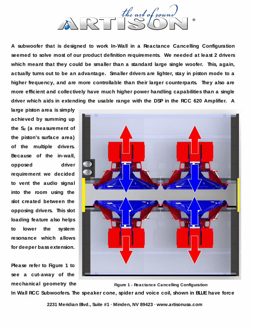
Please refer to Figure 1 to
see a cut-away of the
mechanical geometry the
In Wall RCC Subwoofers. The speaker cone, spider and voice coil, shown in BLUE have force Figure 1 - Reactance Cancelling Configuration

2231 Meridian Blvd., Suite #1 ∙ Minden, NV 89423 ∙ www.artisonusa.com
applied to it via the voice coil’s motion thru the magnetic field. This force also generates an
equal and opposite reactive force that tries to move the magnet structure and speaker
frame, shown in RED, in the opposite direction. Since the components in RED are rigidly
attached to the aluminum cabinets, reactive forces are mitigated due to the opposite
cabinet’s reactive forces transmitted through the aluminum cabinet and connecting plates,
shown in YELLOW. The cabinet assembly itself completes the mechanical circuit of the
system and allows these reactive forces to always be canceling one another out
dynamically as the speaker cones go through both the positive and negative strokes. In
addition to creating a vibration free inert system, the efficiency goes up and harmonic
distortion is reduced.
The Driver
Our first challenge was to create a small long
throw driver that would fit flush into a standard 2 x
4 wall and would have enough cone area to be
effective. The driver size came out to roughly 4”
x 6”. Our goal was the have the equivalent
output of a 12” woofer (The RCC 640). This
required some significant design engineering on
the driver suspension that would allow an overall
linear motion of at least 25.4 mm [1 in]. To make
a long story short it took a computer 4-5 hours
per simulation and 14 different designs to come
up with the surround shape and material that
gave us what we wanted. Figure 2 is an actual
FEA (Finite Element Analysis) computer
generated plot of the surround at the extremes of Figure 2 - Suspension Linearity

2231 Meridian Blvd., Suite #1 ∙ Minden, NV 89423 ∙ www.artisonusa.com
the drivers throw. Figure 3 is a sequence of images of the internal stresses the surround has
the cone moves through one full cycle that came from the FEA. Notice the evenness of the
colored hoop stress lines throughout circumference of the surround. The design of the
driver’s surround has been optimized to maximize the amount of piston area and minimize
the area needed on the woofer basket for terminating the surround.
Figure 3 - Surround FEA Motor Structure
X-Max is defined as how far a speaker cone can move without distortion and is an important
factor for all subwoofers because it determines “how loud and how low” they can effectively
be used. We decided to use a new motor design where the voice coil overhangs the
magnetic gap with a very large primary high grade Ferrite magnet. This design increases
efficiency and still provides a very long throw. In our case we were able to achieve and X-
Max of 13 mm or 26 mm of linear throw, 115% of that number is generally considered usable
piston movement. What all of this means in English is that our woofer drivers have peak to
peak linear throw of just over 1”. This is a huge achievement in such a compact driver.

2231 Meridian Blvd., Suite #1 ∙ Minden, NV 89423 ∙ www.artisonusa.com
A cross section of the driver
shows some of the unique
aspects of our final woofer, see
Figure 4. Note the structure
created by the inverted dust
cap and the cone. There is a
circular portion of the cone that
is carried approximately 1/3rd
of the way from the voice coil
former to the surround
attachment which gives the
assembly a very strong but light
mechanical construction. The
spider is flat which allows for a linear movement in both the positive and negative directions.
The Back Plate, Pole Piece, and the Face Plate which make up the magnet assembly are
similar to a typical ceramic motor assembly but much deeper to allow for cone motion. The
Pole Piece is significantly extended above the face plate with the Neo Magnet to create a
more linear magnetic field, making the voice coil linear throughout its long throw. The gap
looks to the voice coil to be very long and very high energy. The result is increased
efficiency and long linear travel.
Damping Material
All speakers use a damping material inside the speaker cabinet. This allows the air pressure
put into the interior cabinet to be effectively reduced by turning the air molecules kinetic
energy into heat via frictional loss. Commonly used damping materials are cotton, wool or
fiberglass we chose a lesser known option, activated charcoal. The benefits of using
Figure 4 - RCC 4" x 6" Woofer Cross-Section

2231 Meridian Blvd., Suite #1 ∙ Minden, NV 89423 ∙ www.artisonusa.com
activated charcoal come from its natural ability to circumvent one of the basic principles of
speaker design. The immutable relationship of how low in frequency a speaker can play is
how large the interior cabinet volume is; the larger the cabinet the lower the frequency by
nature of lowering the cabinet resonance. This is due to air having a fixed density, relative to
altitude, and that mass of air molecules vibrate at a specific resonance. Air pressure is
simply a measure of the rate of collisions the molecules have with each other in a given
volume. The only viable option up until now has been to exponentially increase the size of
the cabinet volume or to increase the amplifier output power.
The activated charcoal allows a process called Physical Adsorption, not to be confused with
absorption, which is related to osmosis. This type of adsorption is a molecular level attraction
that occurs on the surface of the charcoal. The surface area is microporous meaning the
surface has tiny small pores which came from the activation process of incineration. Just
one gram of activated charcoal will have over 500 sq. meters (5,400 sq. ft.) of surface area.
Imagine the adsorption process as a negative pressure sink inside the cabinet or a magnet
for air molecules. The massive surface area of the pore structure on the charcoal is always
attracting the air molecules ‘detaining’ them on the surface not allowing them to collide as
often. The reduced pressure inside the cabinet, effectively the woofer drivers act as they are
in a larger cabinet, lowering the system resonance and extending bass response. This also
allows the system to accept more EQ from the amplifier and out-perform a subwoofer of the
same physical size without the cabinet stiffness limiting the bass extension.
The System Assembly
Because our goal was to have an In Wall Subwoofer that would effectively compete with a
High Performance Floorstanding System we decided to use 2 pairs of 4” x 6” drivers in the
smaller design (RCC 320 PC and RCC 320 R) and 4 pairs in our larger models (RCC 640 PC
and RCC 640 R). A typical 12” driver has an Sd of between 420 – 490 cm2. Our final design

2231 Meridian Blvd., Suite #1 ∙ Minden, NV 89423 ∙ www.artisonusa.com
has an Sd of approximately 640 cm2 in the larger system. The RCC320-PC System looks like
the photos in Figure 5. The combined effects of the Reactance Canceling Configured
multiple drivers, Slot Loading, Adsorptive damping material and huge power handling make
this design able to perform at levels of extended deep bass in a small enclosure with much
less power than most other subwoofers. By adding an additional subwoofer module to the
amplifier the system performance adds 3 dB to the efficiency and 6 dB to the sensitivity.
Figure 5 – RCC320 PC Subwoofer Module
All Aluminum Enclosures
We chose Aluminum as our cabinet material because of its stiffness to mass ratio and
because we could make a very thin wall which maximizes internal volume. The typical MDF
cabinet would have to be prohibitively thick to be rigid enough for a good quality enclosure.
The properties of aluminum make it the perfect choice for a subwoofer that needs rigidity but

2231 Meridian Blvd., Suite #1 ∙ Minden, NV 89423 ∙ www.artisonusa.com
must have a thin wall. The relatively thin wall allows the internal volume needed to support
the response of the drivers and still have a small enclosure. Aluminum provides the strength,
structural properties and the damping characteristics that we wanted for our subwoofer.
Figure 6 shows a comparison of Aluminum to other popular materials.
Unlike a number of manufacturers who use an open extruded aluminum cabinet and add a
baffle, we use a closed extrusion and CNC the holes for the drivers, etc. We do this because
it eliminates any chance for air leaks and prevents “Bell Mode Resonances” which are
common with open extruded metal enclosures.
Item UnitRegular
Thermoplastic
Polyester
BMC
Aluminum
Die CastingWood
Steel
Stainless
1 Gravity 1.10-1.40 1.7-2.0 2.57-2.96 0.8-0.95 7.19
2 Shrinkage % 0.9-0.4 0.3-0.05 0.45-0.35 NA NA
3 Tensile Strength kg/c㎡ 200-800 300-1500 600-1800 NA 1100-2100
4 Compression Strength kg/c㎡ 500-1200 800-2000 100-300 NA 1800
5 Flexure Strength kg/c㎡ 600-1000 700-2000 560-1800 NA 700
6 Impact Strength kg/c㎡ 5-40 10-70 1-3 NA 4-6
7 Heat Deflection Temp. ℃ 80-160 >200 NA NA NA
8 Electric voltage Resistance KV/mm 12-25 9-25 NA NA NA
9 Arc Resistance Sec 50-100 120-200 NA NA NA
10 Water Absorption 24hr% 0.1-0.3 0.15-0.5 NA NA NA
11 Corrosion Resisance High High Low High Low
12 Design Flexibility High High High Medium Low
13 Raw Material Cost Medium Medium Medium Low High
14 Tooling Cost Medium Medium Medium Low High
15 Finishing Cost Low Medium High High High
Figure 6 - Material Comparison Chart
The Amplifier
The amplifier that we designed to power this system needed to be as efficient and innovative
as the subwoofer modules it would be driving. Utilizing a cutting edge DSP-based preamp
stage and high efficiency Class D amplifier design allowed us to custom design features into
the product that are vital to both the installer and the end-user. The system offers multiple

2231 Meridian Blvd., Suite #1 ∙ Minden, NV 89423 ∙ www.artisonusa.com
installation applications for the same subwoofer in pairs as well as a single driver module.
We engineered two different sets of equalization curve families to allow optimum
performance from either of the two models that we produce. We also created a Music and
Movie EQ which is selectable via the amplifier IR codes in either application. The Music EQ
sets the frequency response flat with the subsonic filter set at 20 Hz. Whereas the Movie EQ
takes the overall gain up by 6 dB and raises the subsonic filter to 35 Hz, this is most effective
for movie playback and maximizes the system output to put the punch where you need it.
The amplifier topology was designed to be convenient for the installer by placing all of the
critical setup controls on the rear of the chassis and the minimal consumer controls on the
front. This amplifier also has the ability to drive up to four of the smaller RCC 320 modules for
a truly distributed bass system.
Amplifier Features:
• 1 Rack Unit Height with standard 19” rack mount ears
• Front Mounted Consumer Controls:
o System Gain, Power Standby/On, LED Mode Indicator
• Rear Mounted Installer Controls:

2231 Meridian Blvd., Suite #1 ∙ Minden, NV 89423 ∙ www.artisonusa.com
o 1/8” IR Jack
o 1/8” 12 Volt Trigger
o Auto Signal Sense ON/OFF mode
o 2 pairs High-Quality Speaker Binding Posts
o Unbalanced RCA L/R Inputs & Outputs
o Balanced XLR Input
o Digital Phase Shift Adjustment, 0-180°
o Adjustable Low Pass crossover 40-160 Hz with slopes of 12 & 24 dB/oct.
• Amplifier Specifications
• >100dB SNR
• <+ 0.5 % THD+N
• + 0.5 dB Frequency Response (10 Hz – 500 Hz)
• 87% Efficient
• 400 Watts RMS into one Subwoofer Module
• 600 watts RMS into two Subwoofer Modules
System Performance
The proof of the pudding is in the eating so how did all of this technology and innovation end
up. In a word, phenomenal! The system is both musical and well damped. Transient
response is excellent and low bass bloom is as it was recorded on the source material. The
system is dynamic but the vibration of the cabinet and wall is virtually gone. We measured
the system and were able to show results that very closely matched our predictions. Here
are some of the highlights:
• Music mode frequency response -3 dB @ 24 Hz (RCC 640)
• Movie mode output 109dB @ 40 Hz
• 2 Module output of 112dB @ 40 Hz
• System Q = .707

2231 Meridian Blvd., Suite #1 ∙ Minden, NV 89423 ∙ www.artisonusa.com
Distributed Bass Reproduction
We support the use of multiple subwoofers to properly reproduce low frequencies indoors.
The total volume and dimensions of a room are what determine the size and number of the
subwoofers that you need. The larger the room the more piston area and throw, or air
volume, that you need to move. Because the wave length of a 100 Hz signal is
approximately 10’ in air at sea level you can see that the number of wave lengths that can
be generated in a normal room is very small. In most rooms frequencies below 50 Hz will not
generate a single complete wave. Due to the interference of low frequency sound waves
caused by room geometry (parallel walls) there are what are known as Eigen Modes within
virtually all listening rooms. If you were to use equalization to make a subwoofer flat below
100 Hz at a particular listening position and move the microphone a foot or two away from
that position the speaker would no longer measure flat. By using multiple subwoofers in
strategic locations around a room you can mitigate almost all of the uneven room response
and make the room more uniform in its low frequency response, which allows everyone in
the listening area to have the same experience. This idea was impractical with multiple
traditional boxes to trip over but with an in-wall subwoofer it becomes not only practical but
a better solution. There have been a number of studies done on the subject of distributed
bass. Most show that Eigen Modes can be basically eliminated with the use of 2-4
subwoofers. This can easily and sveltely be achieved with the RCC Subwoofer System.