The Arcus Center for Social Justice Leadership
12
151 CHAPTER 16 The Arcus Center for Social Justice Leadership by Studio Gang Architects The Arcus Center for Social Justice Leadership at Kalamazoo College in Michigan is a new, purpose-built structure dedicated to developing emerging leaders and sustaining existing leaders in human rights and social justice. This paper addresses the challenges and achievements of using cordwood masonry (wood masonry is the term we use most) to construct it. The use of wood masonry for the Arcus Center is a key part of the building’s design, and resonates with the center’s social justice mission. In using this method at an institutional scale, we were presented with interesting logistical and technical challenges. However, by merging traditional cordwood masonry practices with contemporary design and building technologies, we were able to explore new and different ways to incorporate the benefits of this traditional method. Why Wood Masonry? The process of building with wood masonry and the values it represents directly informed the Arcus Center’s design and construction. Remaining true to the com- munal history and spirit of this tradition, every stage of the project —the decision to use wood masonry, procurement of the material and its methods of construction and detailing —was approached as a collaboration between the College (our client), (Author’s note: Claire Halpin and Wei-Ju Lai of Studio Gang Architects, Chicago, pre- sented a version of this chapter at the Continental Cordwood Conference in July of 2015. Their paper was subtitled “Merging a Traditional Building Method with Com- mercial Construction Technology.” I was brought in as a consultant in the early design stages, and, prior to construction, Jaki and I trained the expert brick and stone masons in the special considerations for cordwood masonry. We believe this is the largest exam- ple of cordwood masonry in the world, and one of the most beautiful.)
Transcript of The Arcus Center for Social Justice Leadership

151
C H A P T E R 1 6
The Arcus Center for Social Justice Leadership
by Studio Gang Architects
The Arcus Center for Social Justice Leadership at Kalamazoo College in Michigan is a new, purpose- built structure dedicated to developing emerging leaders and sustaining existing leaders in human rights and social justice. This paper addresses the challenges and achievements of using cordwood masonry (wood masonry is the term we use most) to construct it. The use of wood masonry for the Arcus Center is a key part of the building’s design, and resonates with the center’s social justice mission. In using this method at an institutional scale, we were presented with interesting logistical and technical challenges. However, by merging traditional cordwood masonry practices with contemporary design and building technologies, we were able to explore new and different ways to incorporate the benefits of this traditional method.
Why Wood Masonry?The process of building with wood masonry and the values it represents directly informed the Arcus Center’s design and construction. Remaining true to the com-munal history and spirit of this tradition, every stage of the project — the decision to use wood masonry, procurement of the material and its methods of construction and detailing — was approached as a collaboration between the College (our client),
(Author’s note: Claire Halpin and Wei-Ju Lai of Studio Gang Architects, Chicago, pre-sented a version of this chapter at the Continental Cordwood Conference in July of 2015. Their paper was subtitled “Merging a Traditional Building Method with Com-mercial Construction Technology.” I was brought in as a consultant in the early design stages, and, prior to construction, Jaki and I trained the expert brick and stone masons in the special considerations for cordwood masonry. We believe this is the largest exam-ple of cordwood masonry in the world, and one of the most beautiful.)
152 Cordwood Building
builders and architects. From the building’s overall form, to the construction se-quence, to the wall composition and other specific components of the masonry, the design of the building sought to expand the potential of this traditional “hand” method, merging it with newer technologies.
The building’s form was directly informed by its use, context and material. The purpose of the Arcus Center is to bring together students, faculty, visiting scholars, social justice leaders and members of the public to engage in conversation and ac-tivities aimed at creating a more just world.
16.1. The Arcus Center for Social Justice Leadership, Kalamazoo, Michigan. Photo by Steve Hall, © Hedrich Blessing.
16.2. Left, the building’s tri-axial organization addresses three adjacent contexts with trans-parent façades. Right, the gently arced walls of the building’s exterior embrace three distinct outdoor areas that serve the programs of the Center. © Studio Gang Architects

The Arcus Center for Social Justice Leadership 153
It provides a safe, welcoming space in which to have sometimes difficult discussions surrounding issues of injustice, share personal stories and to organize action.
Located at the apex of the Kalamazoo College campus, on a hilltop site that incorporates a major incline, the Arcus Center engages each of its distinct con-texts — the campus, a residential community and an old- growth grove — through transparent glass facades. The arcing masonry walls simultaneously embrace three distinct landscape conditions.
The wings of the plan intersect at an informal meeting space: a crossroads for convening. The presence of a hearth and kitchen for sharing food at the center of the building creates the potential for frequent informal meetings and casual, chance encounters. Smaller meeting rooms and individual workspaces are nestled into the area bordering the main assembly spaces. The building’s visually open, day- lit in-terior, made possible by the large glass facades and clerestory, is designed to support conversation and community by allowing for different configurations and ways of gathering that begin to break down psychological and cultural barriers between people and facilitate understanding.
The building’s tri- axial organization developed from the desire to have the ar-chitecture engage with each context, as well as a study of the shapes that form nat-urally when people gather in large groups. While we envisioned using glass for its transparency, we also wanted the design to resonate with the vernacular of the local architecture and relate to the Georgian brick language of the campus. Yet, while Kalamazoo College has a strong history of social justice leadership that dates back to its founding, much of its campus is comprised of buildings whose style evokes colonial- and plantation- era attitudes.
Looking to identify more socially conscious and environmentally sustainable alternatives, we ex-plored local building traditions. Cordwood masonry appealed to us as a sustainable, more democratic, socially and environmentally friendly method of construction. As a collaborative building process that allows people with a wide range of abilities and strengths to participate in construction, cordwood masonry embodies the values the Arcus Center was founded on.
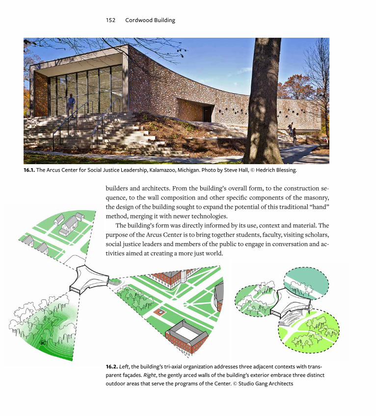
Its aesthetic also appealed to us: the individu-ality of each log, with its unique shape, size, color and growth pattern, could be seen as reflecting the diverse population the Center serves.
16.3. The wings of the plan intersect at an informal meeting space: a crossroads for convening. © Studio Gang Architects
154 Cordwood Building
We were pleased to discover that wood masonry sequesters more carbon than is released in building it, responding to today’s need to reduce carbon pollution — one of many environmental issues embraced by social justice movements. Further solidifying our decision to use this method, we discovered cordwood structures in Michigan dating back more than a hundred years, and we learned that Kalamazoo is located within the growth range of northern white cedar, one of the best species of wood for this use.
Learning from the ExpertsOnce we resolved to use wood for the façade and began seriously looking into the technique of cordwood masonry, we sought out the experts. To learn more about the process and how we might go about scaling it up for commercial construction, we turned to Rob and Jaki Roy of the Earthwood Building School. Rob and Jaki and the collective knowledge of the continental cordwood community have been es-sential to the design, execution and successful application of this technique within a commercial setting.
With the broad base of knowledge that the Roys offered, we could turn our focus to the design challenge of combining this traditional, hand- built method with com-mercial construction technologies, codes and regulations. We were also challenged by some initial skepticism from the client, as well as contractors and engineers who were unfamiliar with alternative building methods. Here, too, the Roys were instrumental in securing confidence in the project, hosting a workshop in northern Michigan for a group of Studio Gang architects, as well as representatives from the client, contractor and Kalamazoo community. Imparting their wisdom and good will, the Roys instilled in the entire team the confidence and enthusiasm neces-sary to forge ahead. They also introduced us to technological advances innovated
within the cordwood community. With this sturdy foundation, we sought to build on these innovations and explore opportunities to use digital tools to play with the surface geometry.
Playing by the RulesWhile the social justice mission and site topography led to the tri- axial organization of the building, we further defined the scheme by establishing rules for the integration of the hand- crafted wood masonry and contemporary steel construction.
The first of these rules relates to the way the
16.4. The individuality of each log, with its unique shape, size, color and growth pattern, could be seen as reflecting the diverse population the Center serves. Credit: Studio Gang Architects.

The Arcus Center for Social Justice Leadership 155
building engages each of its three contexts with a transparent façade. The arcing walls that con-nect these façades, and simultaneously embrace three distinct landscape conditions, are hand- built with wood masonry. The masonry walls are set atop a continuous steel sill, rather than a wood frame, and terminated at each end by a clean steel edge. The steel structure allows for long, unbroken areas of wood masonry walls.
Each wall incorporates an opening, for entry or light, and is treated in a specific way to ma-nipulate its surface geometry. Typically, to create an opening, the geometry of each arcing wall is sliced and then “pushed” or “pulled” as is appro-priate to shape the opening. The concave curva-ture of the walls compresses the masonry, which we learned was an added benefit when it comes to preventing cracking of the mortar.
Each wing of the building and each arced wall is similar but modified to its particular use and context. One wing meets the site at grade, a sec-ond descends along with the grade toward the grove adjacent to the site and a third cantilevers out toward the college campus. Due to the site’s natural change in elevation (approximately 12 feet) and the emphasis on universal accessibil-ity, this cantilevered end of the building projects out above the ground level, allowing the floor inside the building to remain level and for circu-lation to occur underneath. The cantilever had several interesting aspects to its construction. Thornton Tomasetti, the structural engineer of record on the project, recommended that the wood masonry begin at the farthest end of the cantilever, symmetrically on each side, in order to load its most extreme end first and equally. This would ensure that any deflection — while un-likely — would be greatest at this initial loading
16.5. White cedar logs arriving at contractor’s yard. Photo courtesy Miller-Davis Company. Credit: Studio Gang Architects.
16.6. Logs cut to size, set in covered racks and sorted by log diameter. Credit: Studio Gang Architects.
16.7. Logs pre-sorted with random size mix into bins at the job site, ready to be used. Credit: Studio Gang Architects.

156 Cordwood Building
and lessen as the masonry work progressed back, preventing cracking. The same principle was also applied to the masonry sequencing at lintels above openings: masonry was begun at the center of the lintel and then outward toward either end.
Continuing in the vein of the traditional cordwood method, we used locally sourced northern white cedar. Wood was purchased more than a year before con-struction began. It was sorted, cut to length and allowed to dry under protected racks. Prior to the masonry work, it was then redistributed into bins with a repre-sentative “random” mix and brought to the jobsite.
Thermal and Structural ConstraintsThroughout the project, we researched and considered numerous types of wood masonry wall construction: through- wall masonry with a sawdust insulation cavity (as taught at Earthwood Building School workshops), the double- wall technique that has been described in previous papers and in Cordwood Building: The State of the Art, and others. We studied the length of the logs, the composition of the mortar, created mockups, modeled different combinations and tested wall assemblies for their thermal performance in the energy model our engineering team developed.
The possibility of using through- wall masonry exposed on the interior was given much consideration during the design process but ultimately was not used for sev-eral reasons, including the following: the current energy code, which requires a
minimum continuous layer of insulation that would not have been achievable with sawdust insulation to the accepted standards of the governing code authority. Also, the design of the mechanical sys-tem depended on an airtight building enclosure for positive pressurization, which would have been challenging to provide with through- wall masonry due to the potential of air gaps at the log surfaces. Structurally, the cantilevers and façade geometries could not have been achieved with through- wall ma-sonry alone; to satisfy the structural code require-ments for a commercial building, a steel structure and metal stud wall were used in concert with the masonry. Daylighting requirements also contributed to the decision not to use through- wall masonry, as light- colored walls were necessary to reflect ambi-ent daylight back into the spaces. The final design is what we determined was the most appropriate com-
16.8. Typical exterior wood masonry walls are 11 inches thick, with a solid mortar joint. The other layers that make up the wall assembly are described in the text. Credit: Studio Gang Architects.
The Arcus Center for Social Justice Leadership 157
bination for this project. It is in some ways based on a traditional masonry cavity wall that is common in other types of construction, except instead of stone or brick, white cedar logs are used.
The typical wall section is shown below: it consists of 11- inch wood masonry on the exterior, a 1½-inch cavity, a continuous 1½-inch layer of rigid foam insulation with a layer that also serves as a vapor barrier, a stud wall with spray foam insulation that also serves as an air barrier to the system and then the interior finish (which varies throughout the building). This exterior wall assembly provides a total insu-lation value of approximately R- 30.
The wood masonry wall is continuous along each façade, broken only when the wall is terminated by the steel frames at each end. This is made possible by the ma-sonry ties that connect the wood masonry intermittently to the backup stud wall.
Behind the masonry, the one and a half- inch air space allows any moisture pen-etrating the wood layer to drain and weep out of the system. Behind the airspace, the insulation, made up of sheets of rigid foam, creates a continuous unbroken insulation layer around the building. This satisfies one of the energy code require-ments that stipulates a minimum level of continuous insulation (in traditional stud walls, the effectiveness of insulation placed only between studs is reduced by the thermal bridging that occurs at stud locations). The insulation/sheathing layer is a product that includes a reflective film layer on its face that also acts as the weather-proof and vapor barrier in this system. Contrary to traditional wall assemblies in cold- weather areas where vapor barriers are often located on the warm/interior side of the insulation, the dew- point analysis for this air- tight system places the vapor barrier on the sheathing layer.
The sheathing is attached to the stud wall that makes up the exterior wall of the building. Spray foam insulation in between the studs adds more insulation and forms a sealed air barrier that makes the entire wall assembly extremely energy efficient.
The wall composition also aided sequencing during construction. By first erect-ing the steel frame, followed by the stud wall, and then insulated sheathing, interior work was able to occur while the masonry work progressed at its own pace on the outside. This is based on strategies we learned from other cordwood builders who, as common practice, construct the frame of the building and roof first, to allow the methodical masonry work to continue under its shelter.
In the Arcus Center building, there is no roof overhang (as is often suggested by cordwood builders in order to protect the wood façade from exposure to rain). The building’s roof slopes inward, away from the perimeter. Rainwater is collected via drains on the roof surface, so there is no overflow of water over the roof edge.

158 Cordwood Building
The amount of rainwater the façade is exposed to during a storm is no more at the top of the wall than at the base (which would be unprotected regardless of whether or not an overhang were provided).
Pushing the Limits with Digital ToolsAs described above, the continuous masonry walls were an important part of the design. However, in some locations inside the building there was a need for natural light, beyond what was provided by the glass façades and clerestory. In order to allow light and views through the wall without introducing new “slices” or geome-tries, porthole windows were integrated into the wall. The design for these windows was directly inspired by the bottle- end techniques frequently used in cordwood construction; however, due to the energy requirements of the building, it was im-
16.9. Lower left, the steel frame is erected first. Upper left, the roof and inner layers of the outer wall are then completed, allow-ing construction work to continue inside the building while masonry is ongoing. © Studio Gang Architects. Right, the 11-inch wood masonry walls are built next and are capped at the top by a metal coping. Drainage of rainwater is achieved via interior roof drains, allowing the exterior to be free of downspouts and protecting the façade from roof runoff. Credit: Studio Gang Architects.

The Arcus Center for Social Justice Leadership 159
portant in this case that the windows be thermally broken and contain insulated glass, which would not have been the case with bottle ends. Also, with a total wall thickness of nearly two feet, it would have been difficult to source bottles of an adequate length for the wall assembly. Forty- six windows were prefabricated in three different sizes (8- inch, 11- inch and 14- inch diameter) and integrated into the façade. Parameters were given for their heights and general locations, but otherwise we allowed for their flexible placement so that the window installers and masons could collaborate during construction. The method used was to locate pipe sleeves on the wall during masonry construction, integrating the loca-tion into the pattern of log-ends. Later, inner sleeves containing the insulated glass were set into the wall.
There are a few exceptions to the typical 11- inch composition of the wall described above: these in-clude the three “frame” ends of the building where through- wall masonry was used. These locations are exterior- to-exterior and did not have the same thermal and structural requirements as the rest of the building. We took advantage of these locations to use the logs all the way through the wall, expressing the materiality of the logs as much as possible, with thicknesses varying from two feet to approximately six feet. The logs were laid perpendicular to the tan-gent of the curve on the exterior wall. At the interior face of the through- wall masonry, at the frames, the log-ends were cut at an angle, with the resulting wall appearing elongated or elliptical in elevation.
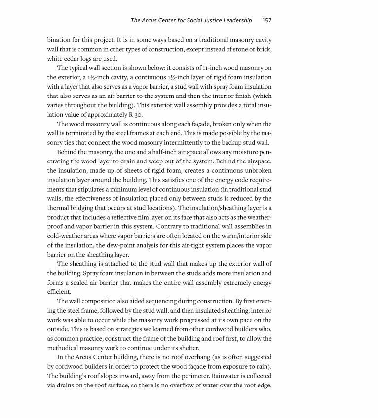
One of the most unique “slices” in the building’s wood masonry façade is the warped wall. The geom-etry of this wall — concave on one side, convex on the other — forms an eye- shaped window opening perpendicular to the wall. To create this slice, we modeled the wall in 3- D, then sliced the geometry at even intervals to create 2- D shapes that served as the
16.10. The wood masonry exterior is built around 46 prefabri-cated insulated window units of varying sizes, integrated into the log pattern. See also Figures 16.1 and 16.9 (right). Credit: Studio Gang Architects.
16.11. The three entrances are framed by wood masonry through walls, beginning two feet wide at the steel-framed ends and increasing in depth up to six feet further in; possibly the longest log-ends ever used in a cordwood wall. Photo by Steve Hall, © Hedrich Blessing.
160 Cordwood Building
basis for custom metal studs. The subcontractor used a digital file of the 2- D shapes to cut the stud profiles. Each stud was slightly different, with the curved profile straightening incrementally.
Placed precisely along the wall, the studs created the armature for the “warped” shape. With the addition of the sheathing insula-tion layer, it became a smooth surface upon which the wood masonry wall was then built. The logs were likewise cut at an angle to form the smooth surface of the wall.
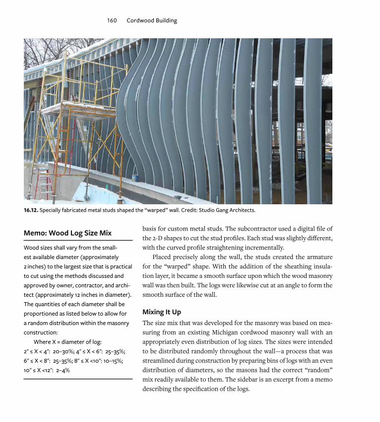
Mixing It UpThe size mix that was developed for the masonry was based on mea-suring from an existing Michigan cordwood masonry wall with an appropriately even distribution of log sizes. The sizes were intended to be distributed randomly throughout the wall — a process that was streamlined during construction by preparing bins of logs with an even distribution of diameters, so the masons had the correct “random” mix readily available to them. The sidebar is an excerpt from a memo describing the specification of the logs.
16.12. Specially fabricated metal studs shaped the “warped” wall. Credit: Studio Gang Architects.
Memo: Wood Log Size Mix
Wood sizes shall vary from the small-est available diameter (approximately 2 inches) to the largest size that is practical to cut using the methods discussed and approved by owner, contractor, and archi-tect (approximately 12 inches in diameter). The quantities of each diameter shall be proportioned as listed below to allow for a random distribution within the masonry construction:
Where X = diameter of log: 2" ≤ X < 4": 20–30%; 4" ≤ X < 6": 25–35%; 6" ≤ X < 8": 25–35%; 8" ≤ X <10": 10–15%; 10" ≤ X <12": 2–4%

The Arcus Center for Social Justice Leadership 161
The goal of this distribution is to allow for some flexibility in sizes while ensuring an even distribution of random sizes of logs and to avoid having many identical sized logs repeated. The higher percentage of smaller logs is intended to maintain a higher log- to-mortar ratio, and allow for more flexibility in log placement during con-struction of the masonry wall.
In addition to the above specifications, a set of “rules” was outlined in the drawings, stipulat-ing that the logs were to be randomly and evenly distributed by size, with a maximum gap at tan-gent points of the logs of one inch; that primary checks must be within 45 degrees of bottom cen-ter; and that only full logs were to be used (no
16.13. The warped wall in its completed state. Credit: Studio Gang Architects.
16.14. The masons maintained a good balance of log sizes through-out, while keeping a constant minimum width of mortar joint. Credit: Studio Gang Architects.

162 Cordwood Building
splits). Beyond these stipulations, the masons working on the project placed the logs according to their judgment and collaborated with carpenters to cut custom logs at an angle where needed at through- wall locations and warped wall, as well as with other trades such as window installers to integrate the porthole windows into the mix.
Not the EndAlthough we were presented with numerous challenges in scaling this method for a commercial building, we believe we achieved numerous successes and learned many lessons that can be passed along to the cordwood community and to the architec-ture and construction professions at large. Perhaps these lessons will inflect future cordwood innovations. While the wood masonry tradition has been advanced, for the most part, by those searching for sensible, cost- effective and energy- efficient building techniques for their homes, we suggest that the environmental and cost benefits of this technology could be leveraged at a larger scale in future public and institutional buildings like the Arcus Center. How can this be accomplished?
To promote the increased use of wood masonry for mechanically conditioned buildings, the techniques developed and lessons learned at the Arcus Center could be formalized into standard details, material and installation specifications and assembly diagrams for reference and adaptation. In addition, the method used for calculating carbon sequestration and assessing the environmental benefits of this material versus alternatives could result in its recognition by regulatory agencies and environmental responsibility advocates like the United States Green Building Association (USGBC), resulting in further benefit to building owners using wood masonry.
For us, the Arcus Center represents a new hybrid typology blending a social, educational, cultural and civic program type. We are proud that it also represents a new hybrid method of construction, blending this traditional hand method with commercial technology, and we hope that the Arcus Center can inspire further use of this energy- saving, renewable, collaborative method in large- scale construction projects.
Studio Gang Architects studiogang.comJeanne Gang, Todd Zima, Margaret Cavenagh, Claire Halpin, John Castro, Ana Flor Ortiz, Wei- Ju Lai, Lindsey Moyer, Rolf Temesvari, John Wolters.Engineers: Thornton Tomasetti (structural); Viridis Design Group (landscape ar-chitect/civil), Diekema Hamann Engineering (MEP, fire protection).