The Architecture Centric Development Method - SCS...
57
The Architecture Centric Development Method Anthony J. Lattanze February 2005 CMU-ISRI-05-103 School of Computer Science Carnegie Mellon University Pittsburgh, PA 15213 Abstract Functionality is a measure of how well a system does the work it was intended to do, but functionality is not all that matters in software development. Properties like interoperability, modifiability, and portability also matter as much as functionality does. These properties are determined primarily by the software structure – or the software architecture. While many structures can satisfy functionality, few can satisfy the required functionally and the quality attribute properties needed in a system. Achieving quality attributes in a predicable way can only be accomplished by deliberately selecting the appropriate structures early in the development process. This is a radical departure from high speed, lightweight programming methodologies (e.g. XP) that focuses on functionality and prescribes writing software until a product emerges – architectures also emerge in this paradigm. Emergent architectural structures may or may not meet the expectations of the broader stakeholders. Other methods espouse high ceremony processes and heavy emphasis on document production. The Architecture Centric Development Method (ACDM) can be differentiated from these extremes in that ACDM places the software architecture at the center of a development effort rather than software processes. Like architectures in the building and construction industries, ACDM prescribes using the architecture design to drive not only the technical aspects of the project, but also the programmatic issues of a development effort as well. ACDM weaves together product, technology, process, and people into a cohesive lightweight, scaleable development method. 1
Transcript of The Architecture Centric Development Method - SCS...

The Architecture Centric Development Method
Anthony J. Lattanze
February 2005
CMU-ISRI-05-103
School of Computer Science Carnegie Mellon University
Pittsburgh, PA 15213
Abstract
Functionality is a measure of how well a system does the work it was intended to do, but functionality is not all that matters in software development. Properties like interoperability, modifiability, and portability also matter as much as functionality does. These properties are determined primarily by the software structure – or the software architecture. While many structures can satisfy functionality, few can satisfy the required functionally and the quality attribute properties needed in a system. Achieving quality attributes in a predicable way can only be accomplished by deliberately selecting the appropriate structures early in the development process. This is a radical departure from high speed, lightweight programming methodologies (e.g. XP) that focuses on functionality and prescribes writing software until a product emerges – architectures also emerge in this paradigm. Emergent architectural structures may or may not meet the expectations of the broader stakeholders. Other methods espouse high ceremony processes and heavy emphasis on document production. The Architecture Centric Development Method (ACDM) can be differentiated from these extremes in that ACDM places the software architecture at the center of a development effort rather than software processes. Like architectures in the building and construction industries, ACDM prescribes using the architecture design to drive not only the technical aspects of the project, but also the programmatic issues of a development effort as well. ACDM weaves together product, technology, process, and people into a cohesive lightweight, scaleable development method.
1

Keywords: Software Architecture, Software Design, Software Engineering, System Architecture, System Engineering, System Design, Quality Attributes, Enterprise Architecture, Software Development Methods, Software Development Process, Software Development Lifecycle.
2
Introduction In the building construction industry, architects are hired very early in the conceptual phase of construction. They provide models of the building they plan to build to potential stakeholders based on their expectations of what they want and need in a building. The architectural model is the basis from which the detailed designs (blue prints), work breakdown structures, and ultimately construction schedules are derived. In essence, the architect’s model drives the entire construction effort. For building architects, the architecture is the intersection where requirements meet solution space; its where builders, client stakeholders, and managers meet, huddle, and agree on what will be built. This is the underlying philosophy of the Architecture Centric Development Method (ACDM). It has been over twenty years since the introduction of the first software process framework, MIL-STD 2167. Since the introduction of MIL-STD 2167 a number of software process frameworks have been introduced to the software engineering community: CMM, SCRUM, RUP, and Agile methodologies. What the software engineering community has learned over these twenty years is that disciplined software processes are essential for building products in a predictable way. However, just having good processes does not guarantee that a software intensive system will be fit for purpose. Good software processes do not automatically mean that well designed, technically innovative, and cost effective products will emerge. Despite the lessons learned regarding software processes, there are still organizations that do not place value in disciplined processes and holds gurus and technology in reverence. In these environments code is cool, coding is an art form, and disciplined software development processes are for sissies. These teams rely on virtuoso talent, individual heroics, and long hours of overtime for success. This is not engineering nor is it sustainable behavior at the individual or organizational level. Teams that operate this way build systems that are unpredictable in terms of cost, schedule, and the quality built into their products. Clearly there needs to be a balance between technological concerns and process concerns. Striking this balance is what the ACDM is all about. ACDM is a scaleable lightweight method for developing software intensive systems with a product focus that prescribes flexible process activities and artifacts. The Importance of Software Architecture Functionality is a measure of how well a system does the work it was intended to do. However, if functionality were all that mattered, any old chunk of code would do. System properties like interoperability, modifiability, and portability also matter as much as functionality does. These properties are quality attributes. The quality attributes of a software-intensive system are determined primarily by the system’s software architecture. While many structures can satisfy some given functionality, few can satisfy the given functionally and the quality attribute properties needed in the system. Software architectures must be designed to meet the functional and quality attribute needs of a system. Software architectures capture the gross partitioning of the system and expresses the fundamental structural organization of the system elements and the relationships between them. This organization is essential for meeting the functional and quality attribute requirements on delivery day as well as throughout the life of the system. Every
3

software intensive system has a software architecture regardless of whether there is a representation of that architecture. However, having a software architecture emerge is very different from deliberately developing one. If the architecture is not deliberately designed; if the developers proceed to detailed design or code without an overarching blueprint, the architecture of the system will emerge by happenstance. Similarly the quality attribute properties the system possesses will also emerge by happenstance – they might be the right ones, and they may not be. You will get an architecture, and you might not like what you get. Systems built without a well-designed and documented architecture will exhibit unpredictable properties—the system might be modifiable, it might perform as required, and it might interoperate with other systems as required. Software architects define the external properties of the system elements, the topological arrangement of the elements, and the interactions between them to achieve functional and quality attribute requirements. Detailed designers focus on the internal details of the elements. The architecture constrains the downstream designers, thus ensuring that the properties promised by the architecture are advanced in the design and are present in the implementation. Architectures influence the structure of an organization as well. Teams are often assigned to build the “parts” of the system. The division of labor in an organization building a software intensive system will mirror an architecture with all of its strength and weaknesses. For example, elements in an architecture that are tightly coupled, can expect implementation teams that will exhibit high frequency communication patterns, where as loosely coupled architectural elements can expect implementation teams that will exhibit low frequency communication patterns. Managers can use the architecture as a basis to structure teams, plan, track, and cost the effort accordingly. Overview of the ACDM Just as blueprints in the building construction industry guides the construction of a building, the software architecture serves a blueprint that addresses technical concerns and programmatic issues of a project. An architectural focus will:
help refine the functional requirements, quality attribute requirements, and constraints
help set and maintain expectations in stakeholders define the team structure aid in creating more accurate project estimates establish the team vocabulary help identify technical risk early guide the creation of a more realistic and accurate production schedule and
assist in project tracking and oversight provide an early vision of the solution/system
A number of methods have been created by the Software Engineering Institute to help practitioners create better architectures. Some of these methods include: Quality Attribute Workshop (QAW) [1,2], Architecture Tradeoff Analysis Method (ATAM) [1,2], Attribute Driven Design (ADD)[2]. These methods have provided great value to practitioners trying to build better architectures. However, these methods have two main
4

problems. First, they are intervention oriented. These methods were not designed with a particular development philosophy (lifecycle or process) in mind. As such, they do not fit neatly into existing development models or processes without significant tailoring. Little guidance exists that describes how to tailor these methods to fit into an organization’s development model. To maximize their effectiveness, these methods should be used together and this requires significant tailoring. In order to tailor these methods, someone in an organization has to know a great deal about each of them in order to tease them apart, and reassemble them into a cohesive, usable development method/process. This is a risky and difficult proposition in many organizations. The second problem with these methods is that in their originally authored form they tend to be heavy-weight and expensive for the smaller teams, projects, short deadlines, and iterative deliveries. Overcoming these two hurdles has prevented many organizations in industry from embracing these methods, and more importantly, adopting the entire body of work. Organizations are constantly bombarded with emerging methods, tools, and techniques and they must:
• figure out if they are useful • how to use them • how to make them fit together • estimate the costs for adoption • show return on investment
After 20 years of process model promises, this is a tough sell in most organizations. Just as technological components can have mismatch, so can processes, methods, and tools when we try to bring them together in an organization. Software development teams need specific guidance about how to create software architecture in the context of a product development lifecycle. ACDM brings together some of the best practices into a lifecycle development model. The key goals of ACDM are to help software development teams: • Get the information from stakeholders needed to define the architecture as early as
possible. • Create, refine, and update the architecture in an iterative way throughout the lifecycle
whether the lifecycle is waterfall or iterative. • Validate that the architecture will meet the expectations once implemented. • Define meaningful roles for team members to guide their efforts. • Create better estimates and schedules based on the architectural blueprint. • Provide insight into project performance. • Establish a lightweight, scalable, tailorable, repeatable process framework. The ACDM is geared toward organizations and teams building software intensive systems and puts the software architecture “front-and-center” during all phases of the project. The method prescribes creating a notional architecture as soon as the most preliminary requirements work has been completed. The architecture is developed early and iteratively refined as a central focus of the project. The architecture is refined until the development team is confident that a system can be implemented and it will meet the needs of the stakeholder community. In ACDM, the architecture is the locus for defining all subsequent processes, planning, activities, and artifacts.
5

Preconditions for beginning ACDM are defining roles for all of the team members. The method describes several roles and their responsibilities. The ACDM essentially follows seven prescribed stages briefly described below. Stage Description Activities and Artifacts 1
Discover Architectural Drivers Meet with client stakeholders to discover and document architectural drivers: high-level functional requirements, constraints and quality attributes.
2 Establish Project Scope
Distill architectural drivers into an architectural drivers specification. Create a Statement of Work and Preliminary Project Plan.
3 Create Notional Architecture
Create the initial architecture which includes a run-time view, code view, and physical view of the system.
4 Architectural Review Review the notional architecture to discover and document risks and issues.
5 Production Go/No-Go
Prioritize and list the risks and issues discovered during the architecture review and decide whether the architecture is ready for production (production step 6) or whether it needs to be refined (refine step 6).
Refine (No-Go) – Architecture needs to be refined 6
Experiment Planning
Team creates experiments to mitigate risks and/or issues that were discovered during the review. Experiments are targeted, planned, technical prototypes that are for the purpose of exploring technical issues associated with the architecture or to further explore the architectural drivers.
7 Experiment Execution and Architecture Refinement
The team carries out the experiments and documents the results. The architecture is refined based on the results of the experiments.
Return to Stage 4, Architectural Review to review the refined architecture. Production (Go) – System or elements of the system are ready for construction 6
Production Planning
Team creates a detailed plan for the construction of the system based on the refined architecture. Each element of the architecture has an “owner” and shepards the construction of the element to completion. The plan schedules time and resources for detailed element design, reviews, construction, test, and so forth.
7 Production
The team executes the production plan and is actively engaged in building the system. Production includes construction of the elements of the architecture, integration of the system, as well as element and system test. Production may result in producing the whole system, parts of the system, or in deliverable increments of the system.
Return to stage 1 and iterate stages as necessary.
6

While ACDM emerged from small teams and projects (4 to 6 team members, 1 to 2 year projects), it is designed to scale up to meet the needs of larger teams and projects as well. In larger projects, the ACDM is used by a core architecture team to create and refine the overall system architecture. The output from this ACDM cycle is an initial partitioning of the system (or system of systems) into sub-elements (or subsystems) and their interactions. Detailed architecting of the various elements is deferred to smaller teams, each using ACDM to architect their part of the system (which may be another system). Later integration of the entire system is undertaken in production stages 6 and 7. The ACDM has been evolved over a five year period (since 1999) on small projects and is now being further refined for use on larger projects in industry. Agile and ACDM Its unclear what the term “agile” really means – although it is used frequently today to describe software development where coding takes priority over design, documentation, and high ceremony processes. In many agile development methodologies, the emphasis is placed on writing code as soon as possible (as is the case in eXtreme Programming [9]) and the code is “grown” over time. The underlying theory is that today, “the exponential rise in the cost of changing software over time can be flattened or even reversed given modern programming tools, technologies, and practices”1. What often happens in organizations using an agile method is that after a few iterations of growth, the code and the system become brittle and quickly show signs of wear. Since the structures of such systems are not planned based on sound architectural drivers, structures emerge as a consequence of writing code that may or may not meet future expectations. When a point is reached where the system can’t be grown any longer to meet functional and quality attribute needs, agile methods generally prescribe refactoring – which is really redesign. While this approach might work on small scale software products, it quickly breaks down as product, project, and quality attribute needs scale up. In the extreme case, imagine an avionics system that is a couple of million lines of code. Not only is changing the structure of such as system mid-lifecycle impossible in terms of shear volumetrics, a good majority of the flight test would have to be reflown to recertify the system as airworthy. This would be economically infeasible in most cases. Another issue is the psychological impact of asking stakeholders for resources to essentially redesign a system. It might be easy to get stakeholders to fund the development of more functionality, but in practice it is difficult to get them to fund restructuring the system. Restructuring is not visible to most stakeholders, functionality is – which would you pay for if you were in the stakeholders’ shoes? This makes some agile methods unsuitable for anything but small to mid-scale software development projects or products where the structure of the system is well established and well defined. For example, web page development occurs in an environment that is well defined technically and operationally. Constraints might include HTML, support for applets, and the structure provided by a browser. It becomes difficult to grow and maintain systems of any size at all without a clearly defined software architecture that establishes a framework within which the system will be built and grown overtime. Clearly architects can’t design for every future change that might be needed. However, spending a little time early in the development cycle to develop an architecture than can delay, reduce, and in some cases preclude the need for refactoring until much later in the lifecycle. This will lengthen the useful life of a system amortizing development costs
1 Beck, Extreme Programming Explained: Embrace Change, page 21
7

before major redesign, upgrade, or replacement is needed. Despite the time spent early in the ACDM to develop the software architecture, the method is lightweight and fits well in an environment where short development cycles and small teams are the norm. Description of the Method As mentioned earlier, ACDM was inspired by some of the essential techniques that made ATAM, QAW, and ADD successful as well as a number of best practices. ACDM was refined by practitioners building real systems. After 4 years of use, ACDM is still maturing, but balances the technical and process aspects of a development project into a single lightweight development method that scales to meet the needs of small and large teams and projects. ACDM is prescriptive in terms of what is done, yet allows flexibility in how various steps are executed and in what artifacts are created. The following picture, provides an overview of the method.
8

Discover Architectural Drivers
Establish Project Scope
Raw list of high level functional requirements, constraints, and quality attributes.
Artifact(s)
Legend
Statement of Work Architecture Drivers SpecPreliminary Project Plan
Architecture views
Risks and Tradeoffs
Create Notional Architecture
Architectural Review.
Production Go or No-Go Decision
Refine
Production Planning
Plan Experiments
Production
Rim
Stage Activity(s) Dec
Experiment/Research Plans Refined Project Plan Refined Requirements Spec
Production andTest Plans
Execute ExpeRefine Archite
eturn to the appropriate stage and terate as necessary for production,
aintenance, or enhancement
ision ProdNext Step
. 1.
4.
6.
6.
riments
7.2.
cture
Experiment results. Refined architecture Updated initial plans.uce
7.
5.
3.
Detailed Designs Product
s
9

ACDM Preconditions A precondition to beginning step 1 of ACDM is to establish the team roles for project. The recommended roles and responsibilities for ACDM are listed in the table below: Role General Responsibilities Requirements Engineer
Act as lead in gathering and documenting functional requirements; Coordinate quality attribute discovery and documentation; Coordinate creation of the Statement of Work (SOW); Serve as customer liaison; Coordinate test planning and execution.
Chief Architect Coordinate creation of the notional architecture and refining it as necessary; Coordinate architectural reviews; capture and document architectural risks and tradeoffs; Coordinate creation and maintenance of architecture documentation.
Chief Scientist Coordinate the creation and documentation of the experiments and research studies. Coordinate test planning, documentation of the test plan, and test execution.
Managing Engineer
Coordination of the overall development effort. Coordinate the creation and documentation of the preliminary and production plans and schedules. Conduct project tracking and oversight.
Support Engineer
Set up and maintain development support tools (development environments, CM, and so forth). Establish and maintain web presence as necessary. Ensure that the ACDM is followed, record deviations from the method, document changes to the ACDM as required. Establish and maintain a defect logging and tracking processes.
Software Engineer
These are team members whose focus is detailed design and coding of the architectural elements of the system. In small teams, all team members will be software engineers. Assist with responsibilities of other roles as necessary and assigned by the Managing Engineer.
Notice that there are six roles listed here. All team members are responsible for configuration management and quality assurance (led by the Managing Engineer). For each role listed, general responsibilities are listed here – specifics are provided for each stage of ACDM. If your group has less than six members, you will have to assign two or more roles to one or more persons on your team. The managing engineer will coordinate all of the activities that follow. If tools need to be installed and configured before the project begins, the support engineer should do this before the ACDM begins if possible. The ACDM also assumes that the functional requirements and constraints exist but does not discuss in detail how to get them, document them, and organize them. This may seem somewhat naive but this is intentional since requirement gathering, documenting, and organization varies widely even in our small studio projects. While ACDM does not address the gathering of initial requirements and constraints, it will help refine them, clarify them, as the architecture is designed and matures. The relative completeness of the functional requirements varies from project to project and may have to be discovered and refined as a consequence of building the system. Some clients provide a documented list of functional requirements; others just bring ideas to the team. The initial gathering of functional requirements is assumed to have occurred prior to beginning step 1 of ACDM. The requirements engineer will coordinate the gathering and documenting
10

of functional requirements. The term “constraints” as applied in this context can be confusing. A “constraint” is an imposed design decision or a design decision that the architect is not at liberty to make or change. Example constraints include being forced to use a particular operating system, use a particular commercial off-the-shelf product, adhere to a particular standard, or build a system using a prescribed implementation framework. Instantiating ACDM While there are prescriptive elements, ACDM has a great deal flexibility that has been intentionally built into it. Prior to beginning the project, the development team must plan how they will carry out ACDM. They must in effect, instantiate an ACDM strategy for the project. It is difficult to discuss the detail strategic elements of ACDM since the reader is not yet familiar with the method. However some factors that will impact how ACDM is instantiated include: Project/Product Scope Size of the project in terms resources such as the size of
the stakeholder community, the number of developers, and the amount of software that must be written among others. The scope of the effort will dramatically influence many aspects of how ACDM is instantiated.
Volatility of Requirements Requirements volatility will heavily influence the way that ACDM is instantiated in terms of Stage 1, 2, and 3 activities where the architectural drivers are discovered and the notional architecture is created.
Distributed-ness of the Stakeholder Community
In nearly all software development projects, it is impractical to assume that stakeholders will be readily available at a moments notice. Highly distributed stakeholder communities will influence the manner in which the architecture drivers are discovered in Stage 1.
While there are other factors that will influence how ACDM is instantiated, these will be discussed throughout the document as each stage is introduced.
11

Stage 1: Discover Architectural Drivers Preconditions ACDM roles defined. Who System Stakeholders, Development Team Activities Business Goals Presentation, Construction of the Quality Attribute
Characterization Table. Outputs Key architectural drivers: functional requirements, constraints, and
quality attributes. Prioritized attribute characterization. Role Stage 1 Recommended Responsibilities Requirements Engineer
Plan, coordinate, and facilitate the Stage 1 Architectural Drivers Discovery meeting. Configuration of the raw architecture drivers documentation garnered during stage 1.
Managing Engineer
Ensure that the activities of Stage 1 are executed thoroughly and completely. Assist the Requirements Engineer in coordinating stage 1 meeting logistics. Assist requirements engineer in capturing architectural drivers during the Probe and question stakeholders to explore their needs and expectations.
Chief Architect
Chief Scientist Support Engineer
Software Engineer
Assist requirements engineer and managing engineer in capturing architectural drivers during the stage 1 meeting. Probe and question stakeholders to explore their needs and expectations.
In stage 1, the development team will meet with the system stakeholders to discover, define, and document the architectural drivers. The architectural drivers include: high level functional requirements, constraints, and quality attributes. Collectively, they will shape the structure of the system. During this meeting, the development team will gain a better understanding of the context for the system and the primary business drivers motivating its development. This meeting will also help in development environments where the requirements are highly volatile, inexact, or exploratory in nature. The goals of this meeting are for the stakeholders to describe the business and/or mission goals for building the system. This stage has 4 primary steps: Step 1 – Client business context presentation Step 2 – Distillation Step 3 – Define quality attributes Step 4 – Prioritize attribute scenarios Step 1 – Client Business Context Presentation In this step, the client presents an overview of the system from a business or mission perspective. The presentation should describe: - brief history of the organizations - who the major stakeholders are
12

- the current need, time to market expectations, and how the system will meet the need
- the business goals and context as they relate to the project - any relevant technical, managerial, economic, business, or political constraints - the architectural drivers: the high level functional requirements, constraints and
quality attribute requirements that will shape the architecture Step 2 – Distillation The goal of this step is to create a concise list of business and architectural drivers. The development team should pay close attention during the client’s business context presentation so that after their presentation, the team can distill the presentation into a concise list of business drivers and architectural drivers. The list of business drivers will include a list of business needs and goals that the system is intended to satisfy. Next, the development team lists the architectural drivers. The architectural drivers includes: the high level functional requirements, the primary system constraints, and a list the important quality attributes of the system. The team should publicly list a distillation of the stakeholders’ business goals. For example:
Business Goals: • Create a reliable, reuseable
framework for building unmanned space craft and mobile robots. :
Next the team should publicly list of the essential high level functional requirements for the system. These should be broad general statements of functionality. For example:
Functional Requirements: • The framework will provide
standard interfaces to motor controllers, navigation, and flight propulsion systems. :
If it is more helpful, use cases can be used to describe the high level functional requirements for the system, however, the team should not spend lots of time defining functional use cases during this meeting. The focus should be general and at a high-level of abstraction.
13

Next the team should publicly list the constraints for the system. Recall that constraints are design decisions, tools, schedule and resource demands for which there is no flexibility. For example:
Constraints: • The framework must utilitize the
existing hardware and operating systems.
• The framework must be ready for system developers in 6 months. :
During this step, the developers should not simply list what they heard. It is critical that the developers work with the broader stakeholder community during the meeting to ensure consensus for the content of each list. If there are differences of opinion, they should be noted and their resolution taken up at a later date (stage 2). Step 3 – Define Quality Attributes Clarifying and refining the list of quality attributes is the next focus for the team. The team should refer to the list of business goals and functional requirements and invite the stakeholders to offer quality attributes that they deem to be of importance to the success of the system. Referring to the distilled business goals and functional requirement lists above, a list of quality attributes might include: Quality Attribute Reliability Portability Modifiability
Next the team must ask stakeholders to characterize each of these quality attributes more fully. Recall that any of these quality attributes by themselves really doesn’t mean anything and must be cast into the context of the system that is being built. For example: Quality Attribute
Attribute Characterization
Reliability Ability to anticipate and recover from failure
Portability Support for the current family of operating systems (CE, VxWorks)
Modifiability Ability to add new hardware with minimal impact to the framework.
While this table shows a one-to-one correspondence between quality attributes and attribute characterizations, this need not be the case. For each quality attribute there
14

must be at least one attribute characterization, but there might be more than one. As the group develops attribute characterizations for the quality attributes, it may be the case that duplicate/redundant quality attributes are discovered. This is a normal part of the quality attribute refinement and a desired outcome. The stakeholders should agree on a name and characterization for the redundant quality attributes and/or attribute characterizations. This helps all stakeholders understand and agree upon what is meant by each quality attribute name. After the attribute characterizations have been established, the next task is to develop attribute scenarios. The attribute scenarios are short statements that describe an interaction with the system. Attribute scenarios can be differentiated from use case scenarios in that use case scenarios focus on functional responses to stimuli and attribute scenarios focus on quality attribute responses. Quality Attribute
Attribute Characterization
Attribute Scenarios
Reliability Ability to anticipate and recover from failure
A hardware failure causes the operating system to “hang” during mid-flight operations. The defect is automatically detected, the backup system is switched to primary and the faulty system is rebooted. All occurs within 5 minutes.
Portability Ability to support current family of operating systems
A mobile robot is initially implemented using the CE operating system. The robot is scaled up and the operating system is changed to VxWorks to support the new mission. The framework is able to run under VxWorks with no modification to the CE applications or framework.
Modifiability Ability to add new hardware with minimal impact to the framework.
A new servo controller is needed for planetary robot application. The framework is able to support the new hardware with no modifications to the framework and within 24 staff hours.
The addition of the attribute scenarios completes the quality attribute characterization table. Again, while this table shows a one-to-one correspondence between attribute characterizations and attribute scenarios, this need not be the case. For each attribute characterization there must be at least one quality attribute scenario, but there might be more than one to describe various interactions with the system. The scenarios will represent the concerns of the stakeholders. Ensure that each scenario has a well formed stimulus, environment, response, and response measure where:
• The stimulus is the event, demand, or condition affecting the system. • The environment is the condition under which the stimulus takes place. • The response is the desired response of the system to the event, demand, or
condition. • The response measure is the measure by which the response will be evaluated.
15

As an example, consider the reliability scenario from the table above:
• Stimulus: A hardware failure causes the operating system to “hang.” • Environment: During mid-flight operations. • Response: The defect is automatically detected, the backup system is switched
to primary and the faulty system is rebooted. • Response Measure: Occurs within 5 minutes.
Note that this scenario explains what it means for the system to be reliable. It replaces the vague notion of “reliability” with a clear, short, and measurable description of how a reliable system will behave. Every attribute characterization will have at least one scenario. Again, it is OK if redundancies emerge and the group of stakeholders decides to merge or remove quality attributes, attribute characterizations, and/or attribute scenarios as they refine the quality attribute characterization table. Step 4 – Prioritize Attribute Scenarios After attribute scenarios have been generated for each attribute characterization, the group must prioritize the attribute scenarios. Each scenario is rated according to how important it is for the system to satisfy the requirement. Stakeholders prioritize each scenario as follows: Rating Importance Description High If this scenario can’t be satisfied by the system, the system will be considered
a failure. Medium It would be highly desirable for the system to satisfy this scenario, however, if
this scenario can’t be satisfied by the system, the system will NOT be considered a failure.
Low Satisfying this scenario would be a “nice to have.” Once the attribute scenarios are prioritized, the meeting can conclude. The average meeting time for stage 1, will be between 4 and 8 hours. Stakeholder groups should not exceed 20 or so, otherwise it will be difficult to complete the Stage 1 meeting in a single day. If the stakeholder community is large and or geographically distributed, it may be the case that the development team will need to carry out multiple Stage 1 meetings with the various stakeholder groups. The output of the multiple Stage 1 meetings can be consolidated in step 2. In the development environments where the requirements are highly volatile, inexact, or exploratory in nature it may be necessary for the development team to iterate between Stage 1 and Stage 2 with the stakeholders. This will help the development team coalesce the architectural drivers enough so that a notional architecture can be rendered in stage 3.
16

Stage 2: Establish Project Scope Preconditions Stage 1 complete. Raw architectural drivers captured. Who Development Team Activities Refine, clarify, and consolidate the raw architectural information. Outputs Key architectural drivers: functional requirements, constraints, and
quality attributes. Prioritized attribute characterization. Preliminary Project Plan. Statement of Work. Architectural Drivers Specification.
Role Stage 2 Recommended Responsibilities Requirements Engineer
Coordinate the efforts the team to clarify and refine the architectural drivers. Coordinate the creation and configuration of the architecture drivers specification document and the statement of work.
Managing Engineer
Provide tracking and oversight of Stage 2 activities. Ensure that architecture drivers documentation is complete. Assist in coordinating logistics. Assist architect in the creation of the architecture and its representation. Update, refine, and disseminate planning information as necessary. Coordinate the creation and configuration of the Preliminary Project Plan.
Chief Architect
Chief Scientist Support Engineer
Software Engineer
Assist requirements engineer and managing engineer in capturing architectural drivers during the stage 1 meeting. Probe and question stakeholders to explore their needs and expectations.
In stage 2, the development team will utilize the information gathered in stage 1 to establish the scope of the development effort. The goal for the development team is to refine, clarify, and consolidate stage 1 information so that a notional architecture can be created. At a bare minimum, the development team will analyze the architectural drivers and document what the stakeholders expect in the product. While stage 1 is a divergent process where lots of information about the system is collected, stage 2 should be a convergent process that refines and structures information gathered in phase 1. The following sections are listed: • Consolidation of Information • Clarification and Quantification • Structure and Prioritization • Defining Constraints • Documentation While these sections appear below, the reader should not assume that these are explicit temporally ordered steps that must be followed. In practice, all of these activities will occur randomly, iteratively, and some parts will be carried out simultaneously depending upon the project and the nature of the development team. It is also important to note that as you proceed through these steps the architectural drivers will mature – that means
17

change as you further explore them and refine them. This is normal and a desired outcome. Consolidation of Information The first task is to gather all of the information regarding the architectural drivers collected in stage 1 as well as any other available requirements information. If stage 1 was carried out iteratively with multiple stakeholder groups, the information gathered will have to be consolidated. Duplicate functional requirements, constraints, and attribute scenarios should be consolidated into a single statement and/or source. Conflicting information must be resolved with the stakeholders – this will require more interaction with the stakeholder community and is discussed further in the following sections. Clarification and Quantification The development must scour the raw information collected thus far from the system stakeholder searching for unclear, incomplete, missing, and conflicting requirements. Each architectural driver must be clarified and quantified so that they are understandable by all stakeholders and development team members. Each must be measurable and the collection of architectural drivers must be structured: grouped according to importance, difficulty, and/or hierarchy. This is especially critical and most problematic where quality attribute requirements are concerned. The quality attribute characterization table developed in stage 1 helps to clarify the quality attribute requirements. Likewise, each functional requirement must clearly describe
• what is needed • which stakeholders need it • how much (functionality) is needed • how urgently is it needed • how likely is it to change and how quickly
As the architectural drivers are clarified and refined, the development team may need to reengage stakeholders to elicit more information. As the development team iterates with the stakeholders in stage 2 the amount of information should begin to converge. This means that the information obtained is consistent and there is very little new information added to what is already known about the system. Iteration with stakeholders at times may be slow and difficult. However, if the development team finds that there are lots of new requirements and/or new information about requirements is inconsistent with earlier information, this may be a sign of divergence. It may be the case that stage 1 was unsuccessful, that is, the team derived the wrong architectural drivers. There are many potential causes for this: the development team may have engaged the wrong and/or different stakeholders in stage 1 and stage 2; there may have been changes in the system environment, technology, or organization between stage 1 and stage 2. Part of clarification and quantification includes identifying quantifiable measures for the architectural drivers. Again, this is most problematic where quality attribute requirements are concerned; however, the quality attribute characterization table developed in stage 1 will help to quantify quality attribute requirements. Each functional requirement must be checked to ensure that they are clearly qualified and are measurable. We must be able to prove that a product satisfies a requirement – this is impossible if there is not a
18

common understanding of what it means to satisfy a particular requirement. If the development team fails to quantify any architectural driver, they are setting the stage for failure. Structure and Prioritization Functional requirements should be structured. This might be based on priority, dependencies, or both. Some requirements may be more important than others and therefore, it is necessary that they are satisfied first. In an ideal world, key requirements would be independent of one another. Unfortunately, this is usually not the case – before one requirement can be met, another must be satisfied first. Sometimes the dependencies are obvious. It is the responsibility of the development team to make all assumptions explicit – this includes functional requirements priorities and dependencies. The development team prioritized the attribute scenarios according to importance in stage 1. If stage 1 was done iteratively with multiple stakeholder groups, then the development team will have to resolve the inevitable conflicting priorities with the stakeholder communities. In stage 2, the development team must add a second dimension to the prioritization. The development team must prioritize each attribute scenario in terms of difficultly. For each attribute scenario, the development team must estimate and reach consensus on the relative difficulty of satisfying the scenario in terms of: Rating Difficulty Description High The developers are unsure about how to satisfy this scenario or if they can
satisfy this scenario. Medium The developers understand how to satisfy this scenario, and they know that it
will be hard to do. Low The developers understand how to satisfy this scenario, and they know that it
will be easy to do. After prioritizing each attribute scenario, the development team will have a two-dimensional rating for each attribute scenario according to their relative importance and difficulty. Those attribute scenarios that rate high importance and high difficulty will be highest priority scenarios for the team to focus on in subsequent stages. Structure and prioritization of the architectural drivers is essential for setting stakeholder expectations, reasoning about technical options, and planning the work. Defining Constraints The constraints of the system must be evaluated for their impact on the system. Constraints may be technological or programmatic (cost/schedule/man power) in nature. Each constraint and its anticipated impact on the overall system must be spelled out in explicit detail. For example:
19

Type of Constraint Constraint Impact
Technical The system must CORBA middleware.
Performance will be hampered. No control of middleware evolution.
Programmatic (Schedule)
The system must be ready to field in 6 months.
Not all functional elements will be ready. Test may not be as thorough. Cost will be high due to necessary staff overtime hours.
: : : If the set of constraints being imposed on the system seem to be overly restrictive, the development team may seek to relax specific constraints and/or prioritize constraints into three groups. Rating Flexibility Description Not Flexible
The stakeholders are inflexible in relaxing this constraint. If the system does not adhere to this constraint, the system will be deemed unfit/unusable by the stakeholder community.
Some Flexibility
The stakeholders are somewhat flexible in relaxing this constraint however it is highly desirable and preferred that the system adhere to this constraint. If the system does not adhere to this constraint, system fitness/usability will suffer.
Nice-to-have
The stakeholders are flexible in relaxing this constraint. It would be desirable if the system adhered to this constraint, but the overall system fitness/usability will not suffer if the constraint is not adhered to.
Documentation The documentation that the development team produces as a result of their stage 2 efforts includes:
• Architectural Drivers Specification • Preliminary Project Plan • Statement of Work
Architectural Drivers Specification More important than what an Architectural Drivers Specification document is, is what is it not. This should not be a heavy weight, super detailed, requirements specification that is called for in traditional water fall oriented software development (e.g. MILSTD 2167A). This document is basically a description of what was discovered in stage 1 and refined, clarified, prioritized, and organized in stage 2. One suggested organization follows: Project Overview: Describe the business and/or mission drivers for the system. High Level Functional Requirements: Describe what the system must do to satisfy the business and/or mission drivers. Traditional use cases and/or “the system shall” statements can be used to describe the high level functional needs.
20

Constraints: Describe the key system constraints and their relative priorities as derived in stage 2 as well as the potential impact of each constraint on the system. Quality Attributes: Describe the consolidated and/or refined list of quality attribute requirements. Include the two dimensional priorities of importance and difficulty – make sure that the difficulty rating is thoroughly explained. Preliminary Project Plan A primary tenant of ACDM is that the architecture drives all aspects of a project including the structure of the system, plans of the project, structure of the team, and the artifacts created. Early in any project (before there is an architecture) there is not enough information to create a high fidelity estimate for the entire project. However, the team must provide the client stakeholder with an estimate of how long it will take the team to create and refine the architecture. After the architecture is refined and created a more detailed plan called a Production Plan (stage 6) will be created using the architecture as a basis to create the plan. These plans are shown graphically below to illustrate their place on an ACDM project timeline.
Notice that this illustration shows an ACDM timeline where stage 5 is roughly on the mid-point. Those activities prior to stage 5 are discovery oriented where developers gather information to build, refine, and baseline the architecture. Since not much is known about the product, project, or client stakeholders; this period of time is characterized as the Period of Uncertainty. ACDM activities prior to stage 5 are designed to overcome the Period of Uncertainty as quickly as possible. Those activities occurring after stage 5 are
Production go decision
(Stage 5)
Period of Uncertainty Period of Certainty
Stage 1 time
Preliminary Planning
Focuses on • how long it will take to discover the
architectural drivers • create the notional architecture • how many experiments • refining the architecture for
production
Production Planning (Production-Stage 6)
Focuses on • mapping architectural elements to
tasks, schedules, and personnel • how long it will take to design,
construct, and test each element • how long it will take to integrate the
elements of the architecture into a system
21

detailed design and construction oriented. The architecture is baselined and should embody the needs and desires of the stakeholders; this period of time is characterized as the Period of Certainty. The focus of the Preliminary Project Plans is determining how long the team will spend creating and refining the architecture NOT on building the final product. Philosophically speaking, ACDM works best when the team defines the notional architecture, reviews it, and baselines the architecture as quickly as possible. The benefit of this approach is that the Period of Uncertainty is shortened, and the Period of Certainty is reached earlier. Once the Period of Certainty is reached, more accurate estimates for production can be made. The cost, duration, and other resources required for the following activities should be estimated: Stage Stage Description Considerations
1 Working with client stakeholders, development team discovers and documents the architectural drivers.
How many client stakeholder meetings? Travel to client stakeholder locations? Venues and facilities? Materials? Duration?
2 Consolidating the data garnered from stage one. Creating the architectural drivers specification document.
Amount of raw data from stage 1? Need to revisit client stakeholders? Technical writer support? Review of documentation? Duration?
3 Creating the notional architecture. Size and scope of system? Size of architecture team? Duration?
4 Reviewing the architecture Travel to client stakeholder locations? Venues and facilities? Materials? Reproduction costs? Duration?
5 Production Go/No-Go decision. Duration? 6 Architectural Refinement.
Reviewing risks and issues from architecture review; devising and documenting experiment plans to address them.
Number of experiments planned? Duration of each experiment? Amount of experimentation concurrency possible? Documenting the plans? Duration?
7 Executing experiment plans; documenting results; revising the architecture.
Tools? Environments? Engineering talent? Amount of rework on architectural representations? Duration?
Another critical consideration for the Preliminary Project Plan is estimating how many refinement iterations will be required. Recall that after the architecture is refined (stage 7), it will be reviewed again (stage 4). In theory, more risks and issues can be found requiring another refinement (stage 6), experimentation (stage 7), and review (stage 4) iteration. The number of iterations should be estimated. In nearly all cases, at least two
22

iterations will be required. Experience thus far has shown that more than three refinement iterations are probably too many and an indication that requirements are diverging or that some other programmatic or systemic problem is present. The Preliminary Project Plan does not include detailed construction and delivery schedules that are called for early in many other development methodologies. The sad truth is that when complete production schedules and cost estimates are made early in the development lifecycle (before any architecting), the chance that the estimates are even remotely close to the actual production cost and schedule is very slim indeed (some studies have indicated deviations of 500%). This is because there is no way for the development team to know enough about the solution space to predict the resources and time required to build the product. The more unknowns in the architectural drivers, the riskier it is that pre-architectural estimates of the total production of the system will be wrong – very wrong. For this reason, ACDM has teams budget time to explore the solution space vis-à-vis the architecture to better define the architectural drivers. This iterative refinement sets the expectations of the client stakeholders. The development team should not define the architectural drivers to freeze them. Certainly we need to know what architectural drivers are clearly understood, defined, and are not volatile. However we also need to identify volatility in the system and understand how that volatility will affect the underlying structures (e.g. the architecture) of the system. In the building construction industry, cost and schedule is derived from the architecture and the ensuing detailed blueprints of the building – not before [13], [14]. Essentially the architecture is a model that embodies the specification of the thing being built. It is unreasonable to believe it could be any different in the production of software. However, everyday, organizations attempt to create detail production schedules for complex software intensive systems based on vague requests-for-proposals (RFPs) listed in magazines and newspapers far removed from any real stakeholders. The danger is that these early estimates set unrealistic expectations in the client stakeholders. Sometimes (and unfortunately) the need for complete early estimates cannot be avoided for a variety of reasons. If forced to make complete production estimates during the inception of product development, the development team cannot be held responsible for inaccurate schedule and cost estimates. After the architecture of the product has been refined as ACDM prescribes, the accuracy of production estimates increases greatly. The production planned is discussed in Production - Stage 6. Statement of Work The statement of work (SOW) formally documents the relationship between the development team and the client stakeholders, their respective obligations and responsibilities, and sets the context of the project. This is a slightly different definition than those that might be found in industry – especially in defense contracting domains. Often the SOW becomes more like a requirements document than the definition provided here. The purpose of the SOW in the context of ACDM is put formal bounds on the project that both the development team and the client stakeholders can agree to. The SOW establishes boundaries on what the development team is responsible for so that when these bounds are breeched, the development team and stakeholders can renegotiate the boundary and possibly their relationship. The SOW sets the general expectations of all of the participants in the project. The SOW (as intended within ACDM) does not list the detailed requirements, but rather describes the project in general terms, general deliverable products, and general schedules. Though non-
23

specific with respect to details, the SOW must clearly define responsibilities of the development team and the stakeholder community. If this sounds like a precarious balancing act – that’s because it is. The following is a suggested outline for the statement of work. Front matter
• Name of producing organization and authors • Document version and revision history • Approval signatures • Table of contents • List of figures • List of tables • Applicable documents and references • Executive summary
Project Overview
• Introduction • Definition and purpose of this document • Intended audience • Description of the client stakeholders and their organization • Description of the development organization • Product overview • Description of product/project scope – clearly define what is in scope and what is
out of scope. • Assumptions • Project strategy – describe general approach for getting requirements, designing
product, implementation, test, delivery, support, training, and so forth (as applicable)
Deliverables and Responsibilities
• General description of deliverables including technical artifacts, documentation, and services.
• Development team responsibilities. • Client stakeholders responsibilities such as payment schedules, access to
environment and necessary technological elements, access to stakeholders, and so forth
• Criteria for success • Minimal acceptable delivery – the minimal amount of product that can be
delivered and the project would still provide value to the client stakeholder. • Consequences of failure – late fees, penalties, contract termination conditions. • Approval process and authority for project scope changes
24

Stage 3: Create the Notional Architecture Preconditions Stage 2 Outputs Who Development Team Activities Create the notional architecture. Outputs System context, Notional architecture vis-à-vis three views (run-time,
code view, physical view), Updated preliminary project plan. Role Stage 3 Recommended Responsibilities Chief Architect Lead the team in the creation of the architecture and in creating the
representation of the architecture. Configuration of the architecture documentation.
Managing Engineer
Provide tracking and oversight of Stage 3 activities. Ensure that architecture documentation is complete. Assist in coordinating stage logistics. Assist architect in the creation of the architecture and its representation. Update, refine, and disseminate planning information as necessary.
Requirements Engineer Chief Scientist Support Engineer
Software Engineer
Assist in the creation of the architecture and its representation.
In Stage 3 the development team uses the architectural drivers as a basis to create a first rough draft of the architecture or the notional architecture. Again, the underlying philosophy of ACDM is to use the architecture as the blueprint for the entire project not just technical aspects of the project. Just as architects that design buildings create a model of the building they plan to build early in the project and use it as a basis for all planning, construction, and oversight, the architect of a software intensive system must do the same. A key concept behind ACDM is not to spend too much time getting the architectural drivers and creating the notional architecture. This might seem to contradict ACDM’s underlying dependency on software architecture for guiding all other aspects of the project. However, ACDM prescribes iterating on the architecture until it is deemed to be fit for purpose (according to guidelines that will be explained later). The idea here is not to spend an inordinate amount of time developing the notional architecture – assume that it is a rough draft and that it will need some refining. Partitioning The architect should use the architectural drivers obtained in stage 1 and refined in stage 2 to guide the partitioning of the system – especially the quality attribute requirements. In some cases, architects will partition the system to promote modifiability, in other cases a system may be partitioned to make it faster. Constraints may dictate partitioning as well, however those attribute scenarios whose importance is rated as most important will have the most influence on system partitioning. Those rated as important and difficult (H,H) will be the attribute scenarios that the development team must pay the closest attention to.
25

The term portioning means that we have to divide the system into smaller parts that perform some function in the overall system. Each architect approaches the problem of partitioning differently based on the intuition that they have acquired from years of system design and development. Recall that a software intensive system can be viewed from a run-time perspective, code oriented perspective, or a physical perspective. Each architect will approach the design problem from a unique perspective. Some architects initially think about the system as a set of interacting processes, others will think about the code oriented modules that make up the system, some architects prefer to start with the physical hardware that will make up the system. The perspective that the architect takes is not fixed, nor is it important. What is important is that the architect is aware of the perspective that they are taking as they design the system and that they define the system in terms of the other perspectives. Structures and Views Structures and views are often confused – there is an important distinction to be made between them. Structures are real things that are manifested in implemented systems or that will be implemented in system such as processes, threads, data, hardware, source code and so forth. Representations (in the simplest case think of a picture) of these structures are called views. Views represent structures from the three perspectives mentioned earlier. Run-time views: depict runtime elements and structures of the system. Code views: depict code oriented elements and structures of the system. Physical views: depict physical elements and structures of the system. The term element here is used to refer to a part of the system. Elements and their relationships to other elements form structures. Representations of the elements and their relationships are views. The collection of views is the architectural representation. This is a very important distinction: views of the architecture represent elements and their relationships that will be the structures of the system to be built, or of the system that has been built. Recall that all systems have architectures whether they have been explicitly developed and documented or not. In cases where an implemented system has no documented architecture, its underlying structures will have to be discovered and documented. Imagine if a building contractor had to move a wall but had no way of understanding if the wall was a load bearing wall or not. This is the challenge that faces the architect that must modify a system or must build a new system that must interoperate with a legacy system whose architecture is unknown. Architectural discovery will be discussed later – but be forewarned, this is a painful and time consuming process. A SIDE NOTE: This highlights an important distinction between ACDM and agile methods that prescribe writing code as soon as possible. If code is written without a guiding architecture, the underlying structures of the system will emerge at random and the quality attribute properties that they system promote will likewise emerge at random. Agile methods have a place in small system development or where overall system structure is established (e.g. web oriented applications). While a “code first” philosophy will produce some kind of product faster, subsequent changes may be more difficult to accommodate. Essentially, extreme agile methods do not scale up to meet the needs of modestly large system development. While refactoring (redesign) is prescribed by many
26

agile methods, in even modestly large systems, wholesale redesign is impractical. When we think of changes to a system, functionality comes to mind first. However, sometimes we must make a system more secure, fit into a smaller footprint, make it mobile, make it faster, and so forth. These changes are very difficult to accommodate if they impose structural changes to the system. Random designs result in systems that may or may not be able to accommodate these changes. Obviously it is impossible to anticipate every change we will want to make to a system throughout its lifecycle, but if we have an architecture that is deliberately designed and documented, we can predict how difficult changes will be – that is, how much it will cost and how long it will take. The ACDM tries to address the structural needs of the system early to provide an enduring framework for downstream detailed designers and developers, thereby deferring the need for redesign as long as possible. Context Diagram The context diagram establishes what is part of the system, or internal to the system being developed and what is external. Note that elements external to the system can impose design constraints. External elements are typically out of the purview of the developers and might include external stakeholders, devices, networks, and/or entire systems. Context drawings are typically box-and-line drawings or cartoons showing the system boundary (those elements within the system, and those outside the system). There are a variety of methodologies for creating context diagrams such as UML, Yourdon and Jackson Structure Analysis among others. Partitioning and Creating the Views The act of design (which is what the architect does) involves creativity and intuition. This makes the task explaining how to architect very difficult. Once the context diagram is established, the development team will need to create the notional architecture, led by the chief architect. Here is some general guidance for partitioning the system into elements and creating the necessary views of the system. While this information is presented as discrete steps, it would be naïve to believe that these are always fixed, predetermined steps. This is merely guidance for the development team. Select an overall pattern for the system. Some kinds of problems suggest well known, well established architectural patterns. Rarely does a real system exhibit one pattern – typically real systems are comprised of ensembles of patterns. However, many systems have a predominant architectural pattern. Assume that a client needs to sell widgets on the internet – what kind of architectural pattern does this kind of problem lend itself to? The answer is obviously an n-tiered architecture where one tier is a browser, the middle tier contains business rules, and the final tier is a web server. While this seems to be a trivial bit of reasoning, it can be very powerful in that it provides an initial partitioning based on the experiences of many other architects. More implicitly, we can assume that any architectural pattern will promote certain quality attributes while others will be inhibited. For example, n-tier is a special case of client-server. This family of patterns allows clients to be added (scaled) in a very flexible way provided that clients adhere to defined protocols. However, security and performance are inhibited in this pattern. This doesn’t necessarily mean that the selection of n-tier is bad; it means that the architect must weight the tradeoffs
27

between promoting scalability at the cost of security and performance. Recall that quality attributes represent business goals or what is needed in a system to achieve a business goal. The “goodness” of any architectural decision must be weighed in the context of business goals and quality attributes. Quality attributes that may be undermined by the selection of a pattern can be offset by the selection of other mechanisms that can be applied to and refine the initial pattern selection. For example, firewalls or encryption can be applied to offset the security issues exposed by the initial selection of the n-tiered pattern. However, these mechanisms will help promote some quality attributes and will further inhibit others. Obviously while firewalls and encryption will help with security issues introduced by the selection of an n-tiered pattern, performance is further undermined by the use of these mechanisms. Once a pattern is selected the team should document the architectural decision, why it was selected (criteria), rejected alternatives and why they were rejected. Verify the perspective It is essential that we explicitly recognize what perspective by which we are beginning to decompose the system. When we selected a pattern, we are implicitly bound to a starting perspective. The n-tier (or any client-server oriented) pattern represents a run-time oriented perspective. Each perspective allows us to reason about various quality attributes of the system. For example, run-time views of the n-tiered system allow us to reason about the performance of the system; however, we are unable to say anything about how modifiable the server element of the n-tiered system is. To reason about modifiability qualities, we will have to change our perspective to a code oriented perspective and decompose the system from this perspective. Again, we must consider our system from run-time, code-oriented, and physical perspectives. Decompose If you selected a pattern already, then you have already begun to decompose. Imagine starting decomposition with a box labeled as “system.” Assume that this system represents a particular perspective of the system. The “system” must satisfy all the constraints, functional, and quality attribute requirements.
Constraints
System
Functional
Requirements
Behavior Properties
Quality Attributes
28

At the highest level of abstraction, all software intensive systems can be viewed in this manner. Decomposition can begin with selecting a pattern or the system can be decomposed without a particular pattern in mind. Again, the architect must keep in mind what perspective of the system they are considering as they begin decomposing system into its constituent parts. Decomposition is hierarchical and is iterative. The first level of decomposition will by necessity be course grained and subsequent levels of decomposition will add more detail to the architecture. Assume that the system above is decomposed using the n-tiered pattern to guide the first level of decomposition.
Business Logic
Browser Server
This particular perspective is a run-time perspective showing elements of the system as they would appear during execution. For each element in the first level of decomposition, we must define the externally visible services and data that the element provides. This is largely determined by the constraints, functional, and quality attribute requirements the element is responsible for satisfying. After this initial decomposition, the constraints, functional, and quality attribute requirements must be assigned to elements above. Functional Requirements
Quality Attribute Constraint Responsible Element(s)
Provide access (read and modify) to user account information
:
:
Browser, Business Logic, Server
:
Ability to quickly adapt to changes in business environment
:
Business Logic
: : Use Netscape Browser Some functions, constraints, and quality attributes can be neatly assigned to an element for satisfaction. Others will span across multiple elements. This is an important distinction to recognize since a change in the function, constraint, or quality attribute that spans multiple elements could impact all of the associated elements. Similarly, changes in any one of the elements may impact the function, constraint, or quality attribute that depends upon those elements. Once the initial decomposition is decided upon, the development team should document the key decisions driving the decomposition, why it was selected (criteria), rejected alternatives and why they were rejected. Documenting Views As the system is decomposed, each view must be documented by the development team. The Chief Architect is responsible for keeping (configuration and control) of the architecture. Again, the development must consider the system from three perspectives at a minimum: run-time perspective, code oriented perspective, and a physical perspective. Views from each perspective will comprise the architecture, they help designers reason about the properties of the system, and will eventually help detailed designers and developers build the system. The following is a contrived example of a
29

system that shows three views, one for each perspective, illustrating how together they describe the architecture of a system.
This view represents a runtime perspective of the system showing three processes X, Y, and Z. Assume that the user expects processes to be easily interchanged and/or replaced with new processes.
Note that each view supports different kinds of reasoning. The view from the run-time perspective allows designers and implementers reason about run-time aspects such as performance, process boundaries, data flow, and so forth. The code oriented view allows architects to reason about properties such as modifiability and constrains how downstream, detailed designers and implementers can structure the code. Note that at the architectural level of abstraction, the details of what services and data are provided and required are declared by the architect and details of implementation are left to downstream designers. Finally, the view from the physical perspective shows the
This view represents a code oriented perspective of the system showing three processes the essential elements that make up the processes. Common packages for streams, input, and output inherited by the packages that make up the process algorithms help achieve the expected interchangeability expected by the stakeholders
Process X Process Y Process Z
Byte Stream
Process
Process X Algorithm
Process Y Algorithm
Process Z Algorithm
Input Methods
Output Methods
Steams Packages
Code Package
B Inherits from A
A
B
Run-Time Perspective
Code Oriented Perspective
Physical Perspective This view represents a physical perspective of the system showing three processors and how the processes X, Y, and Z map to specific processors.
TCP/IP Network
Process Z
Process ZIntel SGI Apple
Assigned to
Process
HW platform
Network
Process X Process Y
30

physical hardware and how the elements from the run-time view map to physical elements. This view is essential for deploying the system, testing the operational system, allocation of resources, and so forth. Interfaces As the architecture is refined through successive decomposition (and ACDM iterations), the element interfaces will need to be defined. Essentially, interfaces are agreements between elements that define the rules for their relationship. A common question is, “how detailed should the interfaces be?” The more detailed they are, the better it is. A well defined interface codifies the element’s boundary, rules for interaction, as well as what services and data it requires and provides. Not only is there is often a great deal of confusion about how detailed interface descriptions should be, but when the interfaces should be bound. The earlier they are defined the better it is. There are often dire consequences for ill-defined interfaces. Here is an example: Assume that there are two elements being produced by two different teams (or if you like two different individuals). Let’s also assume that the two elements are dependent upon one another and the architect did not define the detailed semantics of the interfaces for the elements. Essentially this means that the agreement for how the two elements will share data, services, control, and so forth has been deferred to downstream designers. If this is the case, the architect will not be aware of the resulting interfaces that emerge. As a consequence, the architect will not be able to guarantee that the properties promised in the architecture will be fulfilled by the ensuing detailed design and implementation. Again, the issue of the interface is less about functionality and more about whether the emerging relationships (e.g. interfaces) between the two elements will be able to support the quality attribute requirements (will it be fast enough, can it support modifiability, and so forth). Ill-defined interfaces can also affect the organization as well. Again, assume that we have two elements whose interfaces are ill-defined. The teams now must haggle among themselves to define the semantics of the interfaces for the elements. When this happens, teams usually spend inordinate amounts of time in meetings trying to establish interfaces that they can agree upon. Sometimes this is easy, other times it can be difficult or impossible – again as the number of people gets larger, the problem becomes more difficult. In extreme cases, teams implementing components will not want to yield for a variety of reasons such as a perceived loss of control or autonomy, potential loss of funding, and so forth. Some of these reasons may be valid, some may not be valid, but this behavior is always destructive to the organization and is a drain on project schedules. More importantly, the resulting compromises may undermine the original partitioning established by the architect, compromising quality attribute characteristics expected in the implementation. There are two general approaches that the architect can take when defining interfaces. First, the architect can define interfaces themselves (working with their technical team of course), or they can defer the definition of the interfaces to others – but guide their definition. The first option is obvious, the second option is less obvious. In the second case, the architect may choose to allow other engineers to define interfaces but they must guide the effort and they must reserve the final say as to when they will be defined and how. The architect then must place the interfaces under configuration control and ensure that all of the properties promised by the architecture still hold. At this point, the interfaces are no longer in the hands of the detailed designers or implementers.
31

Changing the interfaces should be done only with great care and deliberation (such as that provided by a configuration control body of some sort). Subsequent Decompositions – When Are We Done? After the initial decomposition, the team can begin to decompose each of the elements in the first level of decomposition. Some elements require more detail; these elements will require more decomposition. In many cases it is clear when more decomposition is needed. In the example above, it may be the case that the browser element does not need any further decomposition. However, clearly the server and business logic elements will need to be further decomposed. How much decomposition should a development team do, and when are they done decomposing the system into its constituent elements? A software architecture is “done” when it sufficiently constrains the downstream element designers. That is when • The system is partitioned into elements with relationships between them and there
are run-time, code, and physical views documented describing the architecture of the system.
• For each element, the responsibilities are defined and documented. • For each element, the data and services required by the element to meet its
responsibilities are defined and documented. • For each element, the data and services provided by the element are defined and
documented. • The interface(s) for each element is defined. Having defined the architecture, it can be based-lined and the detailed designers can focus inward and design the details of how each element will work. Software architecture design does not replace detailed designs; detail designs complement software architectures and are the necessary next step in system development. Software architectures help to ensure that the essential quality attribute requirements are designed to be part of the system. The architecture becomes the framework in which the detailed designs of elements are created. The detailed element designs must adhere to the architecture to ensure that the properties promised by the architecture can be realized in the implementations. Detailed design is done in the production stage (stage 6). How Long? The team should spend on the order of few days or weeks (depending upon the scope of the system) creating the context diagram and notional architecture and at least three views of the architecture. This assumes that architectural discovery is not needed for legacy systems which will be discussed later. In addition to the architectural work, the development team should review and refine their Preliminary Project Plans as necessary based on this initial architectural work.
32

Stage 4: Review the Architecture Preconditions Notional architecture created – key views provided in slide
presentation. Slide presentations created summarizing business goals and architectural drivers.
Who Development Team and Stakeholders (optional per discussion below) Activities Review business goals and architectural drivers
Analyze the architecture Outputs Problematic architectural decisions and tradeoffs. Role Stage 4 Recommended Responsibilities Chief Architect Present architecture (step 3 below), respond to architectural queries
(step 4 below). Managing Engineer
Facilitate review meeting. Present introductory material (step 1 below).
Requirements Engineer
Present the architectural drivers overview (step 2 below).
Chief Scientist Support Engineer
Software Engineer
Support review by asking probing questions during analysis (step 4) and scribing.
In this stage we conduct a review of the architecture that involves the development team and system stakeholders. The development team should plan sufficient time for the development team and the stakeholder community to meet for a review of the architecture. The purpose of the architecture review is to expose problematic architectural decisions and explicitly identify tradeoffs between alternative architectural approaches or decisions. Architectural reviews can be conducted internally or externally and in most case both will occur. A development team may undertake an internal review to refine the notional architecture and then perform a second review with the stakeholders prior to committing to production of the system. It is strongly recommended that at least one review be conducted with the stakeholders attending. In general, the Managing Engineer should facilitate the proceedings however, various team members will present during the review. The review meeting is conducted in four steps: Step Description Responsible Role
1 Introductions and Expectations Managing Engineer 2 Review of business goals and architectural drivers
• high-level functional requirements • constraints • quality attribute characterization table
Requirements Engineer
3 Presentation of the notional architecture Chief Architect 4 Architectural analysis Managing Engineer
and Chief Architect
33

Step 1: Introductions and Expectations The development team’s Managing Engineer should set the expectations of the attendees by describing the intent of the architecture review meeting. The key points to emphasize are: The purpose of the review is to • ensure that architectural drivers are clearly understood by all • introduce attendees to the notional architecture • identify problematic architectural decisions The purpose of the review is NOT to • fix problems or discuss detailed solutions • criticize members of the development or stakeholder organizations • discuss process or organizational problems. It is important that the group of attendees (development team and stakeholders alike) understand the purpose of the review. Of these concepts, it is critically important that attendees understand the purpose of the review is to find problematic architectural decisions, not fix them. It is the facilitator’s responsibility to stop nonproductive discussions and move the review forward. When the discussion gets off track, the facilitator should record the essential issue, offer to take up the issue at another time, and move on with the agenda. After setting expectations, the facilitator should provide an opportunity to formally introduce the stakeholders and members of the development team. This is best conducted by a round robin opportunity for each member of the group to introduce them selves. Invite each attendee to state: • their name • role in the stakeholder organization, or role in the development team • how they will interact with the system • what they hope to get out of the review Step 2: Review of business goals and architectural drivers The development team should provide a presentation of the business goals and architectural drivers. This provides an opportunity for the development team to test and demonstrate their understanding of the stakeholders’ wants and needs. The development team’s Requirements Engineer will present the business goals that were distilled in stage 1. This provides an opportunity to ensure that the motivation for building the system are still valid and understood by the development team. After reviewing the business goals, the development team will review the high level requirements, constraints, and the quality attribute characterization table refined in stage 2. This should be a summary of what is in the Architectural Drivers Specification Document. Reviewing the architectural drivers is an important step in four respects:
1. refreshes everyone’s understanding of the key constraints, functional, and quality attribute scenarios that will shape the architecture
34

2. ensures that no information was lost or miscommunicated during stage 2 when the architectural drivers were refined
3. ensures that all of the information is still true and correct and hasn’t changed – it’s a way to manage changes in key architectural drivers
4. this information will be used to drive analysis, so it is essential that it is correct, relevant, and commonly understood
Each attribute scenario of the quality attribute characterization table should be reviewed and stakeholders invited to refine the scenarios and/or add to the table as they deem necessary. The scenario prioritization should also be reviewed to ensure that it is still true and correct with respect to importance and any new additions should be prioritized as well (recall that the determination of difficulty is the purview of the development team). This is critically important to review these scenarios with the stakeholders since these scenarios will be used to analyze architecture. If scenarios are added to the utility tree, they will need to be prioritized according to the prioritization described in stage one (importance) and stage two (difficulty). Step 3: Presentation of the notional architecture After the review of the utility tree, the chief architect will present the architecture to the group. They will show each view of the system explaining the overall structure and function of the system. Step 4: Architectural Analysis After the presentation, the group will analyze the architecture using the attribute scenarios in the quality attribute characterization table. The group should focus on the highest priority scenarios – those that are most important and most difficult (for example those scenarios rated as H,H or at least M,H and H,M). Here is how the analysis of the architecture proceeds. • A high priority attribute scenario is selected by the group (stakeholders and
development team). • The facilitator should re-read the attribute scenario out loud to the group and
explicitly list them on a white board or flip chart:
o Scenario stimulus – is the event, demand, or condition affecting the system o Source of the stimulus – the originating entity of the stimulus o Environment under which the stimulus occurred – the condition under which
the stimulus takes place o Element(s) of the system affected – The design elements that will be the
receptors of the stimulus o Response – the response of the system to the event, demand, or condition. o Response measure – the measure by which the response will be evaluated
. • Once the scenario is listed in its entirety, the architect is asked, “Given this stimulus,
from this source, under this environmental condition, effecting artifact, show how the architecture response within the response measure indicated by the attribute scenario.
35

• The chief architect must steps through the architecture using the views created in
stage 3 showing how the architecture responds to the stimulus. During this explanation the development team and stakeholders may query the architect regarding the architecture, with respect to the scenario being analyzed. During this time, if the architect is unsure of some aspect of how the system will respond to the stimulus or to a query, the development team should capture the issue as a risk. If tradeoffs are discovered, they too should be documented as well.
This analysis will generate risks and tradeoffs. A risk is defined as an architectural decision that may not fully satisfy an architectural driver. This could potentially compromise the business goals (since architectural drivers are largely derived from business goals). Tradeoffs are architectural decisions that will have a marked effect on one or more quality attributes. Tradeoffs occur when an architectural decision is made that promotes one quality attribute, but other quality attributes are adversely affected by the decision. Using a back-up data store, for example, is an architectural decision that promotes reliability. However, keeping the back up current consumes system resources, and so affects performance negatively. The tradeoff here is between reliability and performance. This tradeoff could easily be a risk. Whether this decision is a risk or a tradeoff depends on which quality attribute (reliability or performance) is more important to the stakeholders and whether impact to performance is too excessive. If the stakeholders value performance and the impact to performance is greater than the benefit from reliability, then this decision could be a risk. If the stakeholders value reliability and deem the impact to performance acceptable, then this could be a reasonable tradeoff. Sometimes stakeholders expect a certain level of performance and reliability that isn’t easily resolved. This is a case where two quality attributes are said to be in tension. Again, the architecture is the place to identify, reason about, negotiate these contentious architectural drivers. It is impossible to easily identify these areas of contention during detailed design and it is way too late to identify and negotiate their resolution during implementation. When the analysis is complete, the evaluation team will examine the full set of discovered risks and tradeoffs to look for over-arching themes that identify systemic weaknesses in the architecture. If left untreated, these risk themes will threaten the project’s business goals.
36

Stage 5: Production Go or No-Go Decision Preconditions Risks and Tradeoffs from Stage 4. Who Development Team Activities Evaluate review risks, tradeoff information Outputs Decide to go forward with production or refine the architecture. Role Stage 5 Recommended Responsibilities Managing Engineer
Facilitate review meeting. Present introductory material (step 1 below).
Chief Architect Requirements Engineer Chief Scientist Support Engineer
Software Engineer
Support Go/No-Go meeting
During this short but critical stage, the team decides whether the development team is ready to begin producing the system or if they need to further refine the architecture. Each risk discovered during stage 4 should be evaluated for severity and likelihood of coming to fruition. Some risks may be subjective and difficult to quantify. In terms of the go, no-go decision, the team must honestly assess the state of the architecture and the course of the evaluation to determine whether the architecture needs more refinement. In some cases, this need not be an all-or-nothing decision. Perhaps the overall structure is sound, but more refinement is needed on particular elements of the system. In this case, maybe it makes sense to advance the production of certain elements, while other elements are further refined. Care should be exercised if this decision is made. If potential refinements affect the underlying architectural structure or the elements advanced to production, then chaos will ensue. Piecemeal production and architecture refinement should be considered fully before undertaking this approach as ripple effects can be devastating. Are We There Yet? Strong indications for making a decision to begin production might include the following: • The architecture has matured to the point where the downstream designers are
sufficiently constrained such and they are able to use the architecture to guide their design. This typically means that the boundaries of components are defined, responsibilities of the architectural are clearly defined, and interfaces are defined.
• During the review, the architect was able to explain how the system would respond for all of the high priority scenarios and all responses were within the response measures specified by the scenarios.
• There were no major risks uncovered during the review of the architecture that would put the development effort or the resulting implementation at risk.
37

• No radically new architecture drivers, business goals emerged and no major changes to existing architecture drivers, business goals emerged during the review causing major changes to the fundamental architectural structures.
Strong indications for making a decision to continue to refine the architecture might include the following: • The architect was unable to answer probing questions regarding the architecture.
• There were conflicting answers to probing questions about the architecture.
• Key parts of the architecture are yet to be defined.
• The architect had to draw a significant number of supplemental pictures during the evaluation to explain the architecture – this is an indication that the architecture documentation is weak, therefore making it difficult for down-steam designers to adhere to the architecture.
• Numerous risks were found
• Numerous architectural drivers and/or business goals changed between Stage 1 (discover architectural drivers) and Stage 4 (review).
If the team decides to refine the architecture, they will proceed to Refinement – Stage 6. If the team decides to go to production, they will proceed to Production – Stage 6.
Refinement – Stage 6: Plan/Execute Experiments and Refine Architecture Preconditions Risks and Tradeoffs from Stage 4, Architectural Views Who Development Team Activities Evaluate review risks, tradeoff information, plan experiments, execute
experiments, and refine architecture Outputs Completed, documented, experiment Plans; Refined architecture,
updated architecture documentation; Updated project plans. Updated architecture drivers specification
Role Stage 6 Recommended Responsibilities Managing Engineer
Coordinate the scheduling and planning of the experiment plans. Update the project plans. OPTIONAL: Create experiment plans and carry out experiments.
Chief Scientist Coordinate the development and planning of the experiment plans and tracking of the experiment execution. Assist other responsible engineers with their experiment planning and execution. OPTIONAL: Create experiment plans and carry out experiments.
Chief Architect Create experiment plans and carry out experiments. Update the architectural documentation based on the results of the experiments.
Requirements Engineer
Update architecture drivers specification if necessary based on results of the experiments. Create experiment plans and carry out experiments.
Support Engineer
Create experiment plans and carry out experiments. Ensure tools and environments are available and ready to support the execution of experiments.
Software Engineer
Create experiment plans and carry out experiments.
38

In this stage, the development team has decided to further refine the architecture. To refine the architecture, the development team must create plans to address the risks that emerged during the architecture review. These plans must be lightweight so that the team may obtain the information that is needed as quickly as possible, so that the architecture may be refined and reviewed as quickly as possible. Prototypes are nothing new; however, the term “prototype” has been intentionally avoided here. The problem with prototypes is that too often they become the product. A software intensive product that evolved from a prototype will typically have architectural (structures) that evolve and are unknown rather than possess structures that are designed and are well understood. Rarely are prototyping efforts planned. Prototypes by definition do not include the same level of quality as a production articles do. This highlights a key difference between ACDM and methods that prescribe the use of prototypes to “grow” a product. In the ACDM, after the notional architecture has been created it is reviewed and experiments are planned and used to refine the architecture to mitigate risks. In essence, iteration occurs on the architecture, not the product. This is vital since the architecture will be used for all programmatic aspects of the project as well as the technical aspects. In ACDM, the iteration on the architecture occurs as follows:
Production Stage 6 Stage 7
Refine Stage 6 - Plan Experiments
No Go
Go
Stage 5 - Review
Stage 4 - Create Notional Architecture
Return to Stage 1 for
maintenance and
enhancement
Refine Stage 7 - Execute Experiments
Refine Architecture Architecture Refinement
Iteration
Product Refinement Iteration
As this graphically illustrates, ACDM supports both product and architecture iteration and differentiates between them. The value of architecture iteration is that architectures are models of a system, and as such are abstractions of the real thing. However, by identifying risky elements of an architecture and targeting experiments to address the risk, a higher fidelity architectural model can be created. At the end of the architecture refinement cycles, the architecture should not be a “paper tiger,” but a real artifact – that is, a high fidelity model of the system – with examples and data that supports the elements that comprise the architecture. This refinement may also provide insight into the architecture drivers specification that will result in changes to the architecture. Any changes to the architecture, will affect the project plans. Once the architecture has reached stability there is also an opportunity to iterate during production, however, this is covered in detail in production stage 7.
39

Guidance on Planning Experiments The purpose of using experiments is to systematically refine the architecture based on findings from the review conducted in Stage 4. Experiments are used to explore technological elements that are not well understood prior to committing them to the architecture or to better understand an architectural driver. As the latter implies, this may require further interaction with the client stakeholder communities as experiments are planned and executed. The purpose of explicitly planning each experiment and documenting the plan is to clearly state: • The goal of the experiment • How the experiment relates to the architecture • The expected outcomes • Duration of the experiment • The resources required • Description of the experiment • Results of the experiment
40

Experiment plans should be simple 1 or 2 page documents that include the following elements: Experiment Plan Title Element Content Description Experiment ID This is the title or something that uniquely identifies this
experiment. Responsible Engineer
This is the development team member that is responsible for this experiment.
Purpose Describe the reason for conducting the experiment. It is strongly advised that the author explain how the experiment will be used to refine the architecture.
Expected Outcomes Describe what the responsible engineer expects the outcome or outcomes will be of the experiment.
Resources Required List the resources required that include: compute resources (software/hardware), people, time, money, and so forth.
Artifacts These are the artifacts that will be created as a result of executing the experiment such as software, documentation, and so forth.
Experiment Description
Describe the experiment. This includes software that will be written, research to be performed, studies to be carried out, information that will be collected and how it will be collected and so forth.
Duration The amount of time that it is expected to complete the experiment. Must include an explicit start date, stop date, and milestones as applicable. This should be a mini-schedule of events that can be tracked by the Chief Scientist. The Managing Engineer can roll up the durations and dependencies for all the experiments.
Results and recommendations
The responsible engineer must document the results of the experiment. Describe deviations from the expected outcomes and reasons for the deviations. Discuss and deviations from the planned experiment description. Describe recommendations as a result of conducting the experiment.
The experiment planning effort is led by the Chief Scientist. The responsibility for developing the experiment plans and executing them can and should be delegated to the development team members. Small teams can be assigned to experiments. The Chief Scientist will circulate and review the experiment plans among the team members. The Chief Scientist is responsible for ensuring that the experiment plans are created and will work with the Engineering Manager for coordinating their execution in stage 7, and tracking the results of the experiments. The experiment plans will be an integral part of the risk mitigation plan for the team. These risks are real and need to be mitigated – recall the pedigree of these risks:
41

The implication illustrated here is that business goals motivate the architectural drivers. Architectural drivers, especially the quality attribute requirements, are critical to shaping the architecture and will drive the decisions that the architect will make. The architect codifies their decisions in the notional architecture which we review. As a result of the review we uncover risks that are inherent in the architecture. Note that tradeoffs also share this pedigree as well and because of this lineage, the tradeoffs are more likely to be the right tradeoffs to satisfy the business goals. The risks are only risks because they impact or impede our ability to achieve the business goals. It is useful at this time for the group to consider programmatic risks as well and combine the programmatic risks and the technical risks discovered (and hopefully mitigated) into a more comprehensive risk management plan. Experiments can be used to mitigate a variety of risks. Examples include: • Continuing to decompose various elements of the notional architecture to better
understand assumptions • Creating and evaluating alternative architectural approaches • Validating technologies that are not well understood • Validating requirements that are not well understood • Validating ensembles of elements whose quality attribute behaviors, functional
behaviors are not known or cannot be validated unless they are tested • Market research for commercially available components • Building and testing the architectural infrastructure Executing the Plans Based on the experiment planning, the Engineering Manager should update the Preliminary Project Plan as necessary to reflect the experiments that will be executed and coordinate with the client stakeholders (and if necessary approve the schedule and budgets for the experiments). Finally, the experiments must be executed. The Chief Scientist’s role is to track the progress of the experiments, identifying problem areas
Business Goals
Architectural Drivers
Architectural Decisions
Motivate
Form the basis of
Notional Architecture
Codified in
Has
Risks/Tradeoffs
I M P A C T S
42

(technical, schedule, logistical, and so forth), and assisting other responsible engineers in their experiments. Based on what the team learns from the collection of experiments the team will advance their architecture, the team’s understanding of the problem, and the stakeholders understanding of the product/solution. Refining the Architecture As the experiments are completed, the team will need to update the architecture based upon results of the experiments. Updating the architecture can mean updating views, documenting new structures, updating prose descriptions, and so forth. Production – Stage 6: Production Planning Preconditions Refined Architecture. Results of Experiments. Who Development Team Activities Create Production Plan. Outputs Production plans, test plans, estimates, and schedules Role Stage 6 Recommended Responsibilities Managing Engineer
Coordinate the scheduling of the production plans
Chief Scientist Assist the Managing Engineer in creating and documenting the production plans focusing on element design tasks.
Chief Architect Assist the Managing Engineer in creating and documenting the production plans focusing on element design tasks.
Requirements Engineer
Assist the Managing Engineer in creating and documenting the production plans focusing on element and integration testing.
Support Engineer
Assist the Managing Engineer in creating and documenting the production plans focusing on support tasks such as tool maintenance, set up times, back-ups, and so forth.
Software Engineer
Assist the Managing Engineer in creating and documenting the production plans focusing on element development tasks. Some software engineers will be assigned as the Responsible Engineers for elements of the system.
If, after a stage 4 review, the team concludes that the architecture is sound and that all of the inherent technical risks have been sufficiently addressed, they may decide to begin planning for production. Production may mean that the team builds the whole product, or it may mean that part of the system or some subset of the functionality is produced. ACDM supports the notion of iterative product development and integration, however care should be taken when building and deploying a system in a piecemeal fashion. If the system is to be produced iteratively it is critical that the architecture supports the changes anticipated for future production iterations. Even though production may be iterative, the team should have sufficiently refined the architecture so as to minimize production risks. If there are remaining risks, the team should be confident that they are identified and isolated to a single element of the architecture, thereby limiting potential ripple effects as the element is further refined. A critical part of ACDM is creating a production plan that guides the implementation efforts of the team. A crucial part of the production plan is the creation of higher fidelity estimates for the production of the system elements. In addition to production plans, test plans are also produced by the requirements engineer. This is a logical task for this role since the
43

requirements engineer has documented the needs of the stakeholders vis-à-vis the architectural drivers specification. Task Estimation ACDM prescribes using the architecture to derive estimates and plans. The purpose of estimation is to predict • how long it will take for the team to develop the product • how much it will cost to develop the product • what resources will be required ACDM prescribes estimating the size, effort, and resources associated with designing, producing, and testing each element of the architecture and then rolling up the element estimates into an overall system production estimate. The underlying philosophy for this approach to estimation is that since the emphasis in ACDM is to identify architectural elements and iteratively refine them, then the architecture should be used to estimate the effort and guide production. Each element of the architecture will be decomposed in to scheduling elements, essentially creating another view of the architecture. This is illustrated below:
Architectural Element X Technical Architectural View
(Design Elements)
This illustration shows how each element of the architecture is decomposed into schedule elements. Each element then is rolled up to create a system production estimate. ACDM recommends the use of Element-Wise Wideband Delphi Estimation which is a tailored version of the traditional Wideband Delphi Estimation (WDE) [7]. Traditional WDE is often used estimate the size of code level modules [6]. Rather than estimate the detailed code units, Element-Wise Wideband Delphi Estimation is used to estimate the relative size of the architectural elements. While not prescribed, the code oriented perspectives (views) are the most useful for Element-Wise Wideband Delphi Estimation.
Detailed Element X Design Element X Review Element X Construction Element X Test Element X Rework
Activities
start - stop start - stop start - stop start - stop start - stop
Dependencies: Element X depends on Element Y Responsible Engineer: Joe Guru
Duration
Production Schedule View (Schedule Elements)
44

The goal is to estimate how long it will take to produce each element of the architecture. The team must decide how they will determine duration. They may estimate the amount of time it will take to produce each element or they may derive if they choose. For example an organization may feel more comfortable (or have a need to) estimate the size of each element. In some cases, teams will estimate size (e.g. lines of code) and derive effort, cost, and so forth from size estimates. In other cases, teams will estimate effort in terms of time (staff hours) and derive cost from effort. Still other teams will estimate both. In any case, the amount of time that it will take to produce each element must be available (this will become clearer in stage 7). Once the team decides what they will measure and how they will estimate (or derive) production time, they must estimate production for each element. The estimating procedure follows. 1. For each architectural element, a responsible software engineer is assigned (if not
. An Element Estimation Form for each architectural element in the system is
Element Estimate Form
done so already).
2produced by the responsible engineers. An example follows:
System Name: name of the system Element Name: name of the element Responsible Engineer(s): responsible engineer name of the element’sEstimate: value of the estimate Units: units of the estimate (if other than time) Date: date the estimate was made Rationale (optional) ns or discuss any issues engineer can list any reaso
influencing their design.
Note that the name of the estimator is intentionally omitted in the element estimator form. This allows the participants to estimate without fear of reprisal or providing an estimate that is deemed silly or wrong. The following activities should be considered in the estimation of each element. The element estimate form can be enhanced to have separate estimated for each, or they can be rolled-up into a single estimate by the estimator.
45

Detailed Element Design
What resources (staff, material, money, etc) and how much time will each element of the architecture take to design?
Element Review What resources (staff, material, money, etc) and how much time will it take to review each element?
Element Construction
What resources (staff, material, money, etc) and how much time will it take to build each element?
Element Integration
What resources (staff, material, money, etc) and how much time will it take to assemble the elements into a system?
Deployment What resources (staff, material, money, etc) and how much time will it take to install and otherwise deploy the functioning system on destination system and environment?
Element Test What resources (staff, material, money, etc) and how much time will it take to test each element of the system in isolation? This includes building test harnesses for testing elements or the architectural infrastructure so that elements “plugged in” for testing the elements and the architectural infrastructure.
System Test What resources (staff, material, money, etc) and how much time will it take to test the system in its entirety once the elements are integrated? This test refers to testing the system under laboratory conditions before it is deployed in an operational environment.
Operational Test and/or Certification
What resources (staff, material, money, etc) and how much time will it take test the operational system in the operational environment and certify the system? In some cases, the development team must demonstrate that the system performs as required – or performs some subset of functionality flawlessly under operational conditions. System certification is the term used to refer this type of validation. System certification is testing that is conducted with the system on the operational hardware, software, and in the operational environment.
Rework How much rework does the team anticipate? What resources (staff, material, money, etc) and how much time will rework consume?
3. Each element’s responsible engineer collects the element estimate forms from all of
the team members (including the responsible engineers) and computes the minimum and maximum estimates, the average and standard deviation [8] (Presumably the estimates are in time, but they could be in some other units as well. Eventually, time of production for each element will have to be derived or estimated).
46

4. After the first round of estimates, the team meets. Each element’s responsible engineer presents the following for each element (note this form is called a consolidated element estimate form).
Consolidated Element Estimate Form System Name: name of the system Element Name: name of the element Responsible Engineer(s): name of the element’s responsible engineer Min value of the smallest estimate Max value of the largest estimate Mean mean value of the estimates Standard Deviation standard deviation of the estimates Units units of the estimate Date: date the estimate was made
The team should discuss the estimates for each element. A decision should be made for each element as to whether the element will need to be re-estimated or whether the estimate will stand. The team should agree what tolerance should be allowed in each element’s estimate. The tolerance is the standard deviation from the mean estimate for any given element. A low tolerance allows for very little deviation from the mean estimate, a high tolerance allows for more deviation from the mean estimate. A tolerance of 20% from the mean is reasonable value for most systems in most domains, but experience is the best guide for establishing tolerance. The lower the tolerance, the more at risk schedule and cost will be. For those elements that will be re-estimated, the team members should plan to discuss the estimates. Engineers whose estimates are at the high and low boundaries should be prepared to discuss the reasons and issues for their estimates. Proceedings of these discussions should be captured and sent to all team members or the next iteration of estimation. This process should repeat until all element estimates are within the acceptable standard deviation established by the team. With each iteration the estimates will begin to converge. Once the estimation is complete, the Managing Engineer will use the estimates as a basis to create the project schedules. Creating the Production Schedule from the Architecture The architecture should be used as the basis for creating the production schedule. For each element, a responsible software engineer should be assigned whose responsibility it will be to estimate the resources and time required to design, build, and test the element. The element’s responsible software engineer will also coordinate the activities of the developers assigned to build the product. Various views of the architecture, such as a code oriented view, lend themselves well to establishing an initial task breakdown to create the product schedule. Recall the views presented earlier in stage 3. Views such as these should be used to create the production schedule and assign personnel to develop the elements of the system.
47

Consider the following example.
Process X Algorithm
Process Y Algorithm
Process Z Algorithm
Input Methods
Output Methods
Streams Packages
B
A
Package
B Inherits from A
Element assigned to
Developer
From this code oriented perspective we can see that each package will need to be designed in detail and the partitioning of the architecture suggests a division of labor where one developer is assigned to each package for process algorithm X, Y, and Z. Two developers are assigned to the communication infrastructure embodied in the input, output, and streams packages. The ACDM prescribes that a responsible engineer be assigned to the each element of the system to lead the design and development of each element of the system. From this information, work breakdown structures, Gantt Charts and other similar scheduling artifacts can be derived as illustrated below.
48

Representing the Production Schedule The ACDM does not prescribe that any particular schedule representation format be used, but rather that it is derived from the architecture as described above. The illustration below is an example Gantt chart showing a production schedule for the system. Obviously this an incomplete Gantt chart, however, the previous two examples should illustrate how the architecture can be used to guide the allocation of the workforce and derive the project schedule. Again, the artifacts here are not meant to be prescriptions for how to document the project schedule and workforce allocation, these are merely examples of using the architecture to derive project schedule and allocate the workforce. Using the architecture to drive the programmatic aspects of the project (as demonstrated here) is prescribed by the ACDM, how it is documented is not. Each of the elements in this schedule should be estimated by the engineers assigned to build the element and coordinated by the element’s responsible engineer as described above. All of the individual element estimates need to be rolled up to create the system production schedule; dependencies must be identified and resolved; and the whole Production Plan documented by the Managing Engineer. While the Managing Engineer is responsible for the Production Plan, clearly all members participate in its creation. Test Planning During production planning, the Requirements Engineer must devise a specific plan for testing the architectural elements of the system, the system itself, and certifying the system. However, time must be budgeted for testing the elements and the system and must be included in the estimation performed above, however this can be a catch-22 situation. Often it is helpful if the requirements engineer devises a draft plan before the estimation is done to give the team a feeling of the scope and depth of the testing required. It is essential that the Requirements Engineer use the architectural drivers specification to derive the test plans. Remember, the architectural drivers represent the business
Streams Package
Input Package
Output Package
Algorithm X
Algorithm Y
Interface Design
Design Functional
Algorithm Z
Interface Design
Functional Design
Interface Design
Functional Design
Functional Design
Functional Design
Functional Design
Review
Code
Process X
Review
Code
Review
Code
Review
Code
Review
Code
Review
Code
Integrate
Test
Test
Test
Test
Test
Test
: :
49

goals of the client stakeholder. In addition to developing functional test through demonstration, the constraints and quality attributes must also be tested as well. Testing will occur through demonstration and/or inspection. For example, functionality can be tested best through demonstrating the system functionality to stakeholders. Similarly some quality attributes can be demonstrated through observing the system function as well. Consider the case of a quality attribute scenario that describes a performance response time of 15 milliseconds. This quality attribute scenario should be used as the basis for creating test plans and procedures. Other architectural drivers will have to be tested through inspection. For example, modifiability is a quality attribute that should be clearly described through attribute scenarios. However, there is no way that an operational system can demonstrate most facets of modifiability. Therefore, the architect and/or developers will have to show the stakeholders interested in the aspect of modifiability that the system will meet their modifiability expectations. Again, the modifiability attribute scenarios should be used to drive the test of the system (vis-à-vis inspection). Constraints may also be verified using demonstration and inspection techniques as appropriate. A worthwhile exercise for the development team is to revisit the architectural drivers specification before test planning. For each driver, the development team should try to determine whether they can be tested through demonstration or inspection. The requirements engineer can then begin to plan tests for the elements, system, and for certification. The test plan should be reviewed and approved by the client as soon as it is drafted. This sets expectations for both stakeholders and the development team so there are no surprises later for either party. Other Elements of the Production Plan In the real world, there are often many other elements that will have to be scheduled. After the architectural elements are schedule, other elements should be weaved into the plans such as:
• Training • Subcontract/Subcontractor management • Meetings • Documentation (not mentioned thus far) • Vacation • Travel • Installing and maintaining tools
The intent here is not to present a comprehensive list of other elements that will have to scheduled, but rather provide a few common examples for the reader to consider.
50
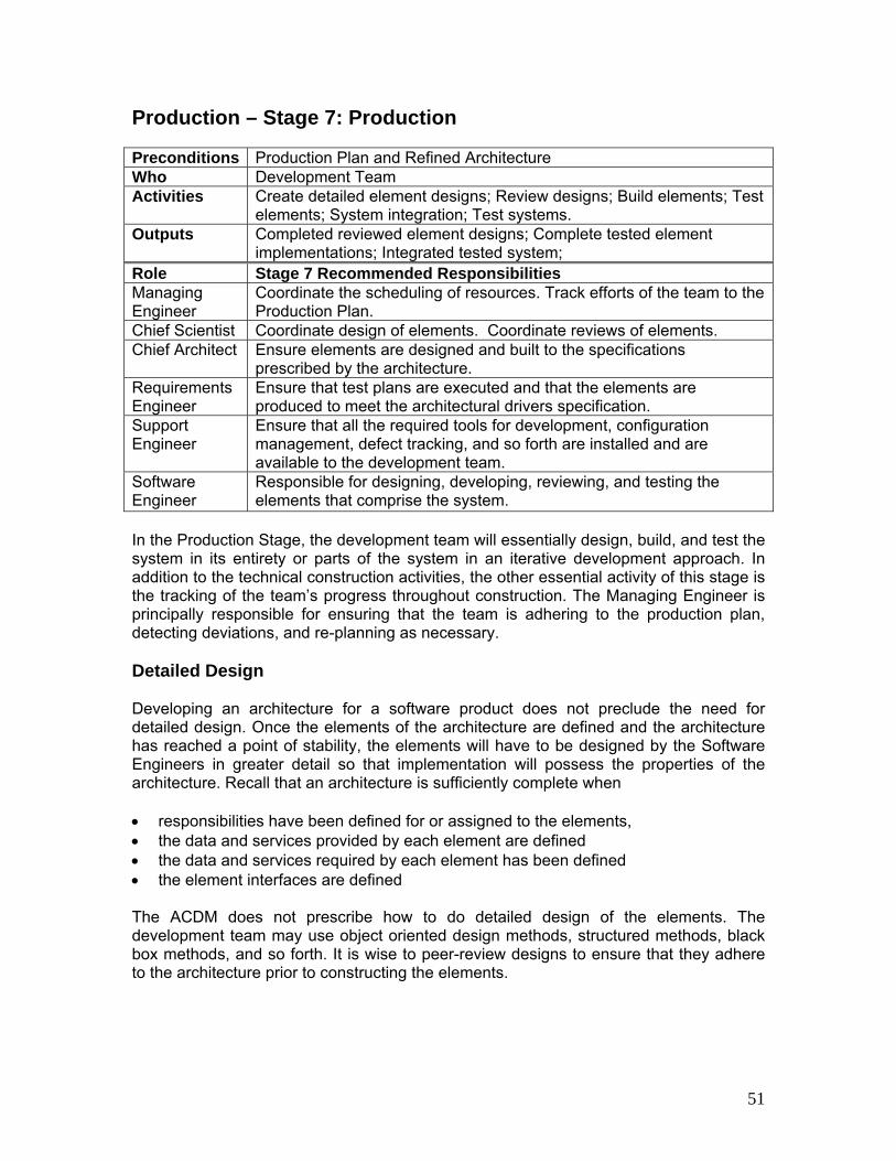
Production – Stage 7: Production Preconditions Production Plan and Refined Architecture Who Development Team Activities Create detailed element designs; Review designs; Build elements; Test
elements; System integration; Test systems. Outputs Completed reviewed element designs; Complete tested element
implementations; Integrated tested system; Role Stage 7 Recommended Responsibilities Managing Engineer
Coordinate the scheduling of resources. Track efforts of the team to the Production Plan.
Chief Scientist Coordinate design of elements. Coordinate reviews of elements. Chief Architect Ensure elements are designed and built to the specifications
prescribed by the architecture. Requirements Engineer
Ensure that test plans are executed and that the elements are produced to meet the architectural drivers specification.
Support Engineer
Ensure that all the required tools for development, configuration management, defect tracking, and so forth are installed and are available to the development team.
Software Engineer
Responsible for designing, developing, reviewing, and testing the elements that comprise the system.
In the Production Stage, the development team will essentially design, build, and test the system in its entirety or parts of the system in an iterative development approach. In addition to the technical construction activities, the other essential activity of this stage is the tracking of the team’s progress throughout construction. The Managing Engineer is principally responsible for ensuring that the team is adhering to the production plan, detecting deviations, and re-planning as necessary. Detailed Design Developing an architecture for a software product does not preclude the need for detailed design. Once the elements of the architecture are defined and the architecture has reached a point of stability, the elements will have to be designed by the Software Engineers in greater detail so that implementation will possess the properties of the architecture. Recall that an architecture is sufficiently complete when • responsibilities have been defined for or assigned to the elements, • the data and services provided by each element are defined • the data and services required by each element has been defined • the element interfaces are defined The ACDM does not prescribe how to do detailed design of the elements. The development team may use object oriented design methods, structured methods, black box methods, and so forth. It is wise to peer-review designs to ensure that they adhere to the architecture prior to constructing the elements.
51

Construction After design, the Software Engineers will construct the elements of the system. The Support Engineer must ensure that development and test environments are available to the Software Engineers as needed. The team may choose to perform Fagan style code reviews [12] or pair programming [9] as desired or deemed necessary. Element and Integrated Test As elements are completed, the Software Engineers are responsible for testing each element prior to their integration into a complete system. A myriad of strategies could be used to perform construction, element, and integrated test. Testing must be closely coordinated with the Requirements Engineer per the testing plan. Tracking the Plan Using Earned Value Earned Value is an objective measurement of how much work has been accomplished on a project. Earned Value, Performance Measurement, Management by Objectives, and Cost Schedule Control Systems are synonymous terms. The essence of Earned Value is that each task is assigned a relative value and the project is credited with that value when the task is completed in its entirety. Using the earned value process, the team can readily determine how much work has actually been completed against the amount of work planned to be accomplished. This helps to avoid the situation where the last 10% of the project takes 150% of the schedule and budget. The ACDM uses the schedule derived from the elements to track the progress of the production stage. This approach works if the entire system is being built, or if it’s being built incrementally, or if only elements are being built. The procedure for using Earned Value follows: • Once the schedule has been derived (in stage 6), the total project time has to be
calculated. The easiest way is to add up the sum of all the task times. Again, these tasks were derived from the elements that comprise the architecture (in stage 6).
• For each element, we need to determine the earned value of the task. The earned
value is derived from the total project time and the estimated time each task takes. For example, assume that we have a project whose rolled up estimate is 1000 hours in duration. Next, assume that we have a task that is 15 hours in duration. The 15 hour task represents 1.5 percent of the 1000 hour total project duration – therefore the earned value for this task is 1.5 [5]. Summarizing thus far [10]:
The total project duration = Σ (task durationT ) for all tasks T The earned value for task T = (task durationT ) / (total project duration)
Tracking progress using Earned Value: • When a task is completed, then it contributes its earned value to the cumulative
earned value of the total project.
52

• No credit is given for partial completion of tasks. Earned value is only accumulated when tasks are completed. This illustrates how important it is to decompose large tasks into smaller tasks as prescribed in stage 6. Using earned value we can derive a reliable measure of percentage of complete, how well the team is performing, deviation from schedule, Summarizing thus far [10]:
Progress or Percentage Complete at time t = (summation of earned value at time t) / (total project duration)
• Performance can be measured by calculating the performance index. This is a measure of how well the team is performing with respect to the schedule. A value close to 1 indicates that the team is performing very well with respect to the schedule [10]: Performance Index = (total project duration) / (summation of earned value at time t)
• Schedule variance is the difference between the actual earned value at time t and the planned earned value at time t. Ideally the difference should be zero indicating that the team is not deviating from the planned schedule. A negative value indicates that the team is behind schedule – the more negative the value, the more behind schedule the team is. A positive value indicates that the team is ahead of schedule – the more positive the value, the ahead of schedule the team is.
Schedule Variance= (actual earned value at time t) - (planned earned value at time t)
Tracking the effort to the plan is the responsibility of the Managing Engineer. The interval (or granularity) that the Managing Engineer tracks the progress of the project will depend upon the number of tasks comprising the project, number of persons on the development team, and the duration of the project. A general rule of thumb is that project progress should be checked, no less than at a two week interval.
Iteration Iteration in the ACDM occurs at two levels. First there is iteration prescribed in the creation of the architecture. Secondly, there could be iteration in the creation of products. The ACDM could be instantiated with a one-pass production cycle or it could be instantiated with multiple production cycles. In the event that the system will produced in an incremental fashion (multiple production cycles), the team has several options for iteration after a production cycle. Here are some things a team should consider as they plan the next cycle through the ACDM. • Stable Architectural Drivers: If there are no changes to the architectural drivers,
then it might be sufficient for the team to iterate on production stages only. • Changing Architectural Drivers: If there are changes in stakeholders, the team
should plan to re-enter the ACDM at stage 1. Often we lament changes in requirements, but requirements changes are the symptoms of a much larger problem. The underlying problem is a change in stakeholders and their expectations. The team should start with the existing Architectural Drivers Specification Document and ask the client stakeholders for feedback on and changes to the architectural
53

drivers. This should be followed up with a meeting that reviews the existing Architectural Drivers Specification and invites the client stakeholder to publicly discuss specific changes to the architectural drivers:
o High-level functional requirements – Are the use case scenarios still valid?
Are there any new functional needs? Is there any functionality that is no longer needed?
o Constraints – Have there been any changes in the fundamental constraints
since the first cycle? Does new or emerging technology affect the existing constraint assumptions?
o Quality attributes – Are the quality attribute requirements still valid? Are the
response measures for the quality attribute scenarios still relevant? Are there any new quality attributes? Are there any quality attributes that are no longer relevant?
After collecting any new information from the stakeholders, the development team should continue with stage 2 to re-establish project scope. In stage 3, rather than create a notional architecture, the team should refine the existing architecture to reflect the changes in the architectural drivers. From here, the ACDM is followed as prescribed in the initial cycle. Postmortem It is a good idea for teams using ACDM to conduct a postmortem at various points throughout ACDM. This should not be an elaborate process, but a low ceremony opportunity for the team to provide feedback on the ACDM instantiation to improve how they are using the method. At the conclusion of each stage, the development team should conduct a postmortem meeting that basically asks the team what went well, what needs improvement, what should we change, what should we do different the next time we execute this stage. The stage postmortem meeting should be coordinated and lead by the Managing Engineer. The following table provides guidance for conduction a postmortem meeting:
54

Aspect Considerations
Did the product meet the expectations of the stakeholders per the architectural drivers specification?
Product Quality
How many defects were present in the product? What was their relative severity? How did the team perform with respect to the schedule (actual vs. estimate)?
Program Schedule
Did the team have to compromise on deliverable features, quality attributes, and so forth to meet cost and schedule objectives?
Team Roles How suitable were the roles to the activities that the team had to carry out? Are any other roles needed; are there any superfluous roles?
ACDM Process Instantiation How well did the method work? What aspects of the process worked particularly well; what did not work? How would the team tailor the process?
ACDM and Legacy Systems So far, ACDM has described green field or new system development. This is rarely the case. Some projects are maintenance oriented and most others incorporate legacy (existing) elements, or legacy systems. In these cases, it is strongly advised that the development team first uncover, document, and review the legacy elements/systems prior to modifying the elements/systems or building systems/elements that will interoperate with the legacy elements/systems. Uncovering the as-built architecture of an existing element or system is referred to as Architecture Reconstruction [11]. Guidelines for how to perform Architecture Reconstruction are outside of the scope of this version of ACDM, but guidelines are provided in [11]. Often the need to interoperate with a legacy system or utilized an existing element is discovered in stage 1 of ACDM. The need to interoperate with legacy systems and elements are constraints for the project. In stage 2, the architecture for the legacy system/element must be reconstructed as part of establishing project scope. Once the as-build architecture of the element/system has been documented, the team can then move forward with stage 3. In stage 3, if the team is building new elements/systems that will interoperate with the legacy elements/systems then the development team should create a notional architecture describing the new “stuff” and how it interoperates with the legacy “stuff.” If the team is modifying the legacy “stuff,” they must show the as-build architecture and the modified architecture. The team will then continue with the architecture review in stage 4, and from here, the ACDM is followed as prescribed.
55

ACDM – Architecture at the Center At this point it should be obvious to the reader how the ACDM puts the architecture at the center of the project from the technological standpoint, but also from the programmatic aspects as well. Consider the following illustration. `
This illustration shows how stakeholders provide business goals which are distilled and refined by the architectural drivers that drive the structure of the architecture. The architecture is iteratively refined, which can in-turn refine the architectural drivers as well as the business goals. Once a baseline architecture is established, as shown thus far in ACDM, it forms the basis of experiments, project plans, test plans, and staff allocation. In the remaining stages, we will see how the architecture is used to create the product and provide tracking and oversight for the project.
Business Goals
Architectural Drivers
stakeholders
provide distilled into
drives the structure of refines refines
Project Plans
Test Plans
Tracking Oversight
Staff Allocation
Experiments
basis of
basis of
basis ofbasis of basis of
Product
Architecture
basis of
basis of
Detailed Designs
56

References:
[1] Clements P., Kazman R., Klein M., “Evaluating Software Architecture: Methods and Case Studies,” Reading, MA: Addison-Wesley, 2002
[2] Bass L., Clements P., Kazman R.; “Software Architecture in Practice - 2nd Edition,” Reading MA: Addison-Wesley, 2003
[3] Carnegie Mellon University/Software Engineering Institute, “The Capability Maturity Model,” Reading MA: Addison-Wesley, 1995
[4] Humphrey, W., “Introduction to the Team Software Process,” Reading MA: Addison-Wesley, 1999
[5] Humphrey, W., “A Discipline for Software Engineering,” Reading MA: Addison-Wesley, 1995
[6] Humphrey, W., “Managing the Software Process,” Reading MA: Addison-Wesley, 1989
[7] Boehm, B., “Software Engineering Economics,” Englewood Cliffs NJ. Prentice Hall, 1981
[8] Singpurwalla, N., Wilson, S., “Statistical Methods in Software Engineering,” New York. Springer, 1999
[9] Beck, K., “Extreme Programming Explained: Embrace Change,” Addison-Wesley, 1999
[10] Pressman, R., “Software Engineering: A Practitioners Approach 6th ed.,” Singapore. McGraw-Hill, 2005
[11] Kazman, R., O’Brien, L., Verhoef, C., “Archtiecture Reconstruction Guidelines, Third Edition,” SEI Technical report CMU/SEI-2002-TR-034,
http://www.sei.cmu.edu/publications/documents/02.reports/02tr034.html
[12] Fagan, M., “Design and Code Inspections and Process Control in the Development of Programs,” Technical Report TR 00.2763, IBM Corporation, Poughkeepsie, New York, 1976.
[13] Heyer, P., “Architects on Architecture,” Walker, New Yorker, 1966
[14] Hamlin, A.D.F., “A History of Architecture,” Longmans, Green, and Company, 1909 I would like to thank Mel Rosso-Llopart, Dr. James Tomayko, Dr. Rod Nord for taking the time to read my work and provide me with valuable feedback. I would like to thank the many Carnegie Mellon University Master of Software Engineering students who have applied ACDM on their software studio projects.
57