The Active Object System Design and Multiprocessor Implementation
214
Research Collection Doctoral Thesis The active object system design and multiprocessor implementation Author(s): Muller, Pieter Johannes Publication Date: 2002 Permanent Link: https://doi.org/10.3929/ethz-a-004453415 Rights / License: In Copyright - Non-Commercial Use Permitted This page was generated automatically upon download from the ETH Zurich Research Collection . For more information please consult the Terms of use . ETH Library
Transcript of The Active Object System Design and Multiprocessor Implementation

Research Collection
Doctoral Thesis
The active object system design and multiprocessorimplementation
Author(s): Muller, Pieter Johannes
Publication Date: 2002
Permanent Link: https://doi.org/10.3929/ethz-a-004453415
Rights / License: In Copyright - Non-Commercial Use Permitted
This page was generated automatically upon download from the ETH Zurich Research Collection. For moreinformation please consult the Terms of use.
ETH Library

The Active Object SystemDesign and Multiprocessor Implementation

c© 2002 Pieter J. Muller

Diss. ETH No. 14755
The Active Object System
Design and Multiprocessor
Implementation
A dissertation submitted to theSwiss Federal Institute of Technology Zurich
(ETH Zurich)
for the degree ofDoctor of Technical Sciences
presented byPieter Johannes Muller
M.Sc., Stellenbosch Universityborn 11th July 1968
citizen of the Republic of South Africa
accepted on the recommendation of
Prof. Dr. J. Gutknecht, examinerProf. Dr. N. Wirth, co-examiner
2002


Bit by bit,Putting it together ...Piece by piece—Only way to make it work.Every moment makes a contribution,Every little detail plays a part.Having just a vision’s no solution.Everything depends on execution:Putting it together—That’s what counts.
— with apologies to Stephen Sondheim.
v


Acknowledgements
I am indebted to several people, without whom completing this disser-tation would not have been possible.
Prof. Jurg Gutknecht enthusiastically supported my project and gaveme free reign to pursue my ideas by providing a comfortable and stimu-lating working environment. Prof. Niklaus Wirth kindly accepted to beco-examiner and provided much-appreciated encouragement. Together,their work inspired me to pursue my doctoral studies in the first place.
I was fortunate to have three outstanding colleagues working closelywith me on the system. Patrik Reali tirelessly maintained the compilerand livened up our office with his jokes. Thomas Frey provided inspira-tion with his novel graphical user interface and countless applications.Bernhard Egger ported the system to the ARM architecture and greatlyimproved the installation process.
Prof. Thomas Stricker generously co-sponsored the six-processor ma-chine used during development and testing. Christian Kurmann andFelix Rauch frequently helped with networking and setup issues.
My other Computer Systems Institute friends and colleagues, espe-cially Andre Fischer, Erich Oswald, Marco Sanvido, and Emil Zeller,ensured a pleasant working environment.
Numerous students and others outside the ETH contributed to theOberon and Aos systems and motivated us with the trust they placedin our work.
Jaco Geldenhuys and Paul Reed scrutinized the manuscript and pro-vided many corrections and helpful suggestions for improvement. BrianKirk provided constructive comments on an early version of the design.
Finally, I’d like to thank my wife Eva for her love, tolerance, andinspiration, and my parents for their unending love and support.
vii

Contents
Abstract xiii
Zusammenfassung xv
1 Introduction 11.1 Motivation . . . . . . . . . . . . . . . . . . . . . . . . . 11.2 Background . . . . . . . . . . . . . . . . . . . . . . . . . 21.3 Contributions . . . . . . . . . . . . . . . . . . . . . . . . 41.4 Overview . . . . . . . . . . . . . . . . . . . . . . . . . . 4
2 Active Object Concepts 72.1 Active Object Computing Model . . . . . . . . . . . . . 72.2 Active Oberon Language . . . . . . . . . . . . . . . . . 11
2.2.1 Object Types and Methods . . . . . . . . . . . . 112.2.2 Synchronization . . . . . . . . . . . . . . . . . . 132.2.3 Active Objects . . . . . . . . . . . . . . . . . . . 142.2.4 Miscellaneous . . . . . . . . . . . . . . . . . . . 14
3 System Structuring Concepts 193.1 Extensible Systems . . . . . . . . . . . . . . . . . . . . 193.2 Modular Structure . . . . . . . . . . . . . . . . . . . . . 203.3 Module Layers . . . . . . . . . . . . . . . . . . . . . . . 213.4 Dynamic Loading . . . . . . . . . . . . . . . . . . . . . 233.5 Service Modules . . . . . . . . . . . . . . . . . . . . . . 243.6 Plugin Modules and Objects . . . . . . . . . . . . . . . 253.7 Commands . . . . . . . . . . . . . . . . . . . . . . . . . 27
ix

4 Active Object Runtime Design 314.1 Runtime Requirements . . . . . . . . . . . . . . . . . . . 314.2 Active Object Language Support . . . . . . . . . . . . . 32
4.2.1 Modules and Dynamic Loading . . . . . . . . . . 334.2.2 Object Model . . . . . . . . . . . . . . . . . . . 344.2.3 Process Model . . . . . . . . . . . . . . . . . . . 344.2.4 Runtime System Calls . . . . . . . . . . . . . . . 38
4.3 Native System Facilities . . . . . . . . . . . . . . . . . . 394.3.1 Memory Management . . . . . . . . . . . . . . . 404.3.2 Device Driver Model . . . . . . . . . . . . . . . 434.3.3 Interrupt Handling Model . . . . . . . . . . . . 44
5 Multiprocessor Runtime Implementation 495.1 Multiprocessor Implementation Issues . . . . . . . . . . 495.2 Runtime Module Decomposition . . . . . . . . . . . . . 525.3 Interfacing with the Environment . . . . . . . . . . . . . 545.4 Protecting Runtime Data Structures . . . . . . . . . . . 565.5 Memory Management . . . . . . . . . . . . . . . . . . . 585.6 Object Storage Management . . . . . . . . . . . . . . . 645.7 Interrupts and Exceptions . . . . . . . . . . . . . . . . . 715.8 Modules, Types and Commands . . . . . . . . . . . . . 735.9 Processes and Synchronization . . . . . . . . . . . . . . 74
5.9.1 Process States . . . . . . . . . . . . . . . . . . . 745.9.2 Process Data Structures . . . . . . . . . . . . . 765.9.3 Process Creation . . . . . . . . . . . . . . . . . . 825.9.4 Context Switches . . . . . . . . . . . . . . . . . 835.9.5 Process Termination . . . . . . . . . . . . . . . . 86
5.10 Object Locking . . . . . . . . . . . . . . . . . . . . . . . 875.10.1 Object Header . . . . . . . . . . . . . . . . . . . 875.10.2 Lock System Call . . . . . . . . . . . . . . . . . . 875.10.3 Unlock System Call . . . . . . . . . . . . . . . . 89
5.11 Object Condition Management . . . . . . . . . . . . . . 905.11.1 Await Statement . . . . . . . . . . . . . . . . . . 915.11.2 Await System Call . . . . . . . . . . . . . . . . . 915.11.3 Evaluating Conditions . . . . . . . . . . . . . . . 93
5.12 Handling Multiple Processors . . . . . . . . . . . . . . . 945.13 Kernel Services . . . . . . . . . . . . . . . . . . . . . . . 96
x

6 System Services 996.1 Files . . . . . . . . . . . . . . . . . . . . . . . . . . . . . 99
6.1.1 File Systems . . . . . . . . . . . . . . . . . . . . 1006.1.2 Disk Drivers . . . . . . . . . . . . . . . . . . . . 103
6.2 Communication . . . . . . . . . . . . . . . . . . . . . . . 1056.2.1 Internet Protocols . . . . . . . . . . . . . . . . . 1066.2.2 TCP Agent Services . . . . . . . . . . . . . . . . 1146.2.3 Network Drivers . . . . . . . . . . . . . . . . . . 116
6.3 User Interface . . . . . . . . . . . . . . . . . . . . . . . . 1186.3.1 Display Drivers . . . . . . . . . . . . . . . . . . 1186.3.2 Input Drivers . . . . . . . . . . . . . . . . . . . 122
7 Application Case Studies 1257.1 Oberon for Aos . . . . . . . . . . . . . . . . . . . . . . . 1257.2 VNC Viewer . . . . . . . . . . . . . . . . . . . . . . . . 1287.3 Other Applications . . . . . . . . . . . . . . . . . . . . 130
8 Evaluation 1338.1 Comparison with Related Systems . . . . . . . . . . . . 133
8.1.1 Multiprocessor Research Operating Systems . . . 1338.1.2 Unix and Related Operating Systems . . . . . . 138
8.2 Performance Measurements . . . . . . . . . . . . . . . . 1448.3 Portability and Flexibility . . . . . . . . . . . . . . . . 150
8.3.1 DNARD port . . . . . . . . . . . . . . . . . . . 1518.3.2 Java Environment . . . . . . . . . . . . . . . . . 152
8.4 System Size . . . . . . . . . . . . . . . . . . . . . . . . 152
9 Conclusion 1559.1 Summary . . . . . . . . . . . . . . . . . . . . . . . . . . 1559.2 Future Work . . . . . . . . . . . . . . . . . . . . . . . . 158
A Module Sizes 161
B Technical Notes 165
C Alternative Interrupt Handling Model 173
List of Figures 181
xi

List of Tables 183
Bibliography 185
Curriculum Vitae 197
xii
Abstract
Today’s pervasive operating systems are large agglomerations of soft-ware with growing resource requirements in every new release; both fortheir development and their operation. Fortunately, with the Oberonproject Wirth and Gutknecht have demonstrated that it is possible todevelop interesting, practical systems with light resource requirements.
We describe the design and implementation of a generally applicablesystem more powerful than Oberon, but still comparatively simple andtransparent. It is based on a lean and efficient extensible kernel intendedfor varied hardware environments — servers, workstations, embeddedcontrol systems, and small mobile devices.
The kernel primarily acts as a runtime environment for the ActiveOberon language, which uses an active object concept for concurrency,and exclusive regions, combined with a general await statement, forsynchronization. In a related project the kernel was reused as the basisfor a Java virtual machine, demonstrating its flexibility.
The system was implemented for Intel IA-32 symmetric multiproces-sor machines, where it schedules active objects to run in parallel, but italso runs on singleprocessor machines. A student has ported it to theIntel StrongARM processor, popular in mobile devices.
This work makes three main contributions. It resulted in the re-lease of a reliable and flexible system that is powerful enough for realapplications. It relates experience with active objects and the elegantawait synchronization statement. Finally, it serves as a new exampleof the lean software approach to system design. Arguably, by focusingon the essential, such systems can perform their task more securely andreliably than conventional operating systems.
xiii

xiv
Zusammenfassung
Die heute verbreitetsten Betriebssysteme sind grosse Ansammlungenvon Softwareelementen, und bei jeder neuen Version wachsen die Res-sourcenanforderungen, sowohl fur die Entwicklung als auch fur den Be-trieb. Wie Wirth und Gutknecht indessen mit dem Oberon-Projekt be-legen konnten, ist die Entwicklung interessanter, praktischer, mit wenigRessourcen auskommender Systeme durchaus moglich.
In der vorliegenden Arbeit werden Design und Implementierung ei-nes allgemein einsetzbaren Systems beschrieben, das leistungsfahiger alsOberon ist, bei vergleichbarer Einfachheit und Transparenz. Das Systembasiert auf einem schlanken und zugleich leistungsfahigen, erweiterba-ren Kern, der sich fur verschiedenste Hardwareumgebungen wie Server,Workstations, eingebettete Kontrollsysteme und kleine Mobilgerate eig-net.
Der Kern dient hauptsachlich als Laufzeitumgebung fur die Active-Oberon-Sprache, welche die Konzepte aktive Objekte fur Nebenlaufig-keit und exklusive Regionen, kombiniert mit einem allgemeinen await-Statement, fur Synchronisierung verwendet. Die Flexibilitat des Kernswurde in einem verwandten Dissertationsprojekt aufgezeigt, bei dem erals Grundlage fur eine Java virtuelle Maschine verwendet wurde.
Das System wurde fur Intel IA-32 symmetrische Multiprozessor-Rechner implementiert, wo es aktive Objekte parallel ablaufen lasst,funktioniert aber genauso auf Einprozessor-Maschinen. In einem Stu-dentenprojekt wurde es auf den Intel StrongARM Prozessor portiert,der haufig bei Mobilgeraten eingesetzt wird.
Folgende Hauptbeitrage werden in der vorliegenden Studie prasen-tiert: Ein zuverlassiges und flexibles Betriebssystem wurde entwickelt,das leistungsfahig genug ist fur echte Anwendungen. Im weiteren wirduber die gemachten Erfahrungen mit aktiven Objekten und dem elegan-
xv

ten await-Synchronisierungsstatement berichtet. Schliesslich wird einneuartiges Beispiel des lean software Ansatzes zum Systemdesign auf-gezeigt. Derart entwickelte Systeme durften, indem sie sich auf das We-sentliche konzentrieren, ihre Aufgabe sicherer und zuverlassiger erfullenals herkommliche Betriebssysteme.
xvi

Chapter 1
Introduction
1.1 Motivation
Modern pervasive operating systems are large agglomerations of soft-ware built in years of work by large groups of developers. Their re-source requirements seem to mirror the effort placed into construct-ing them. Fortunately, the Oberon project has demonstrated that itis possible to develop interesting, practical systems with little man-power [134]. The outcome of the Oberon project was a simple, efficientand transparent operating system that was later described as lean soft-ware [38, 79, 133] — software that is concentrated on the essential andexcludes the inessential.
In this dissertation we attempt to follow in the footsteps of the Obe-ron project to design and implement a multiprocessor operating systembased on a lean kernel for active object-based systems. The aim was todevelop a generally applicable system more powerful than Oberon, butstill comparatively simple and transparent.
Our motivation is the belief that system software does not have to begigantic to be useful or powerful. A sustainable approach to computingis more desirable than a reliance on Moore’s law to support ever-growingsoftware systems, sometimes with countless ‘features’ of doubtful utility(but great marketability).
The specific goals for our project were to:
1. Design a lean and efficient kernel for general active object-basedsystems. The kernel should be applicable in many areas, e.g.,
1
2 Chapter 1. Introduction
in an operating system similar to Oberon, in a server operatingsystem, in an embedded control system or as an operating systemfor small devices (i.e., mobile computers). Therefore, it shouldalso be realizable on a wide range of hardware, from powerfulmultiprocessor server machines down to modest hand-held andwearable devices.
2. Implement the kernel on powerful industry-standard machines,specifically the Intel 32-bit multiprocessor system architecture.
3. Use the kernel as a testbed to implement a general-purpose activeobject-based operating system. The system should host its owndevelopment environment and other applications like servers.
4. Port the current ETH Oberon system to run in an active objecton the system, providing compatibility with existing Oberon ap-plications.
To achieve the flexibility demanded by the first goal, while keepingto the standard of leanness and transparency set by Oberon, the kernelshould be little more than a runtime environment for a type-safe activeobject-based language, with the possibility of ‘plugging in’ additionalcapabilities.
The active object runtime system (Aos kernel) that was developed tofulfil these goals forms the basis of an extensible operating system (Aossystem), which was created by implementing several system servicesusing active objects.
1.2 Background
Oberon language. An important reason for the Oberon system’sleanness is that it is wholly based on the equally lean and powerfulOberon language [98, 132], which allows the system to be structuredas a collection of shared dynamically-loaded modules. We adopted asimilar language-based approach from the start.
Active Objects. Already before the start of our project Gutknechtstarted to extend the Oberon language with direct support for concur-rency and active objects were identified as a suitable abstraction [45].
1.2. Background 3
The resulting Active Oberon language was selected as the basis for oursystem as it retains the leanness and transparency of Oberon and has apowerful and clean concurrency model.
One may argue that the Oberon system’s single-process multitask-ing model contributes to its leanness, because it obviates the need forconcurrency protection mechanisms. However, this model, althoughwell-suited to an isolated single-user system, is insufficient in a moregeneral environment including networking or other inherently concur-rent components. Additionally, it is incompatible with multiprocessormachines, and we therefore had to replace it with a more general con-currency model, at the cost of adding some complexity to the design.
Native Oberon. The original Oberon system (called Ceres Oberon inthis document) was implemented natively on the custom-designed Ceresworkstation with little concern for portability. Nevertheless, due to itsleanness, modular system design and Oberon language abstraction, itwas soon ported to run as an application on many different operatingsystems and hardware architectures. The system was also extended tosupport persistent objects [44] and a document-oriented user interfaceand component architecture [63].
As there was a need for an Oberon system running natively on mod-ern personal computers, the author ported the ETH Oberon system tothe industry standard PC architecture in a previous project. The result-ing Native Oberon system [74] resembles the original system for Ceres,but due to the more diverse and complex hardware environment somelower-level modules were expanded and generalized. By concentratingon open hardware standards like IDE, VGA, VESA and PCI the imple-mentation effort was kept within bounds while supporting a wide rangeof hardware.
Native Oberon has proven itself in teaching and day-to-day use andhas been the basis of many projects: undergraduate [24, 35, 41, 58,59, 87, 115], diploma [25, 57, 73, 111], postgraduate [30, 77] and in-dustrial [49, 110]. A notable project was its adaption into a prototypeactive object runtime system and singleprocessor server system calledEamon [30, 31].
Although Native Oberon is a separate system, it has influenced theAos kernel and system significantly, and the experience gained duringits development is referred to in some of the discussion here. The system

4 Chapter 1. Introduction
was initially used as cross-development environment for Aos. Finally,it was ported to run as an application on Aos, allowing existing ETHOberon applications to run on Aos, thereby allowing the system to hostits own development environment.
1.3 Contributions
The main contributions of this work are the following:
1. It resulted in the release of a reliable and flexible system that ispowerful enough to be used in real applications.
2. It relates experience with active objects in the Active Oberon lan-guage. Although active objects are little more than objects com-bined with lightweight processes, a controversial aspect of the lan-guage is its general await statement for process synchronization.We show with practical experience that this elegant synchroniza-tion concept can be applied effectively in a real system.
3. It serves as a new example of the lean software approach to systemdesign. For example, a system with only 50KB of kernel codeand 150KB of operating system services and application code canperform useful tasks, such as serving dynamic web pages on anoff-the-shelf multiprocessor machine. Arguably, by focusing onthe essential, it can perform its task more securely and reliablythan a conventional operating system.
1.4 Overview
Chapter 2 describes the active object computing model and the ActiveOberon language.
Chapter 3 describes the structure of the active object system (Aossystem).
Chapter 4 describes the design of the active object runtime system(Aos kernel).
Chapter 5 describes the multiprocessor runtime implementation in de-tail.

1.4. Overview 5
Chapter 6 describes the active object-based device and service ab-stractions provided by the Aos system.
Chapter 7 presents various application case studies.
Chapter 8 compares the system with related systems and presentsperformance measurements.
Chapter 9 concludes and discusses future directions.
Appendix A shows the sizes of the modules of the implementation.
Appendix B contains additional technical notes on the implementa-tion.
Appendix C describes an alternative interrupt handling model.

6 Chapter 1. Introduction

Chapter 2
Active Object Concepts
This chapter summarizes the active object computing model and theActive Oberon language.
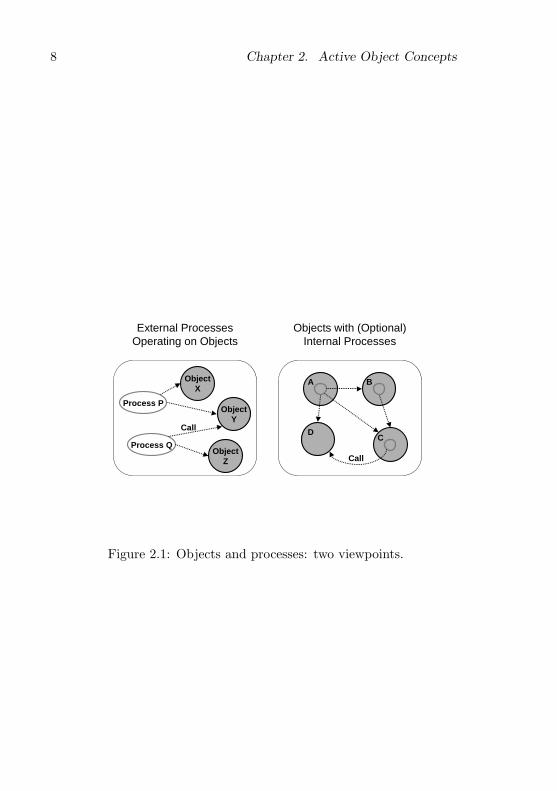
2.1 Active Object Computing Model
When adding concurrent processes to an object-oriented system, one oftwo viewpoints can be taken, illustrated in figure 2.1. On the left is asystem of objects with external processes operating on them. On theright is a system of active objects with internal processes specifying theirintrinsic activity.
In the external process model processes and objects are independententities. Processes modify the state of objects by calling their methods.They interact with each other by operating on shared objects. Forexample, in the figure, process P and Q interact by accessing sharedobject Y , which must be suitably protected against conflicting accesseswith some synchronization mechanism.
In the active object model, a process is encapsulated in an object. Aprocess is always an integral part of an object, created when the objectis instantiated. As in the first model, the active objects can interact bycalling the methods of shared active or non-active objects. The differ-ences between the two viewpoints may be subtle and controversial [66],but we believe active objects present a more natural, integrated modelof concurrency.
Similar to normal objects, active objects have state and supply meth-
7
8 Chapter 2. Active Object Concepts
ObjectX
ObjectY
ObjectZ
Process P
Process Q
A B
CD
External Processes Operating on Objects
Objects with (Optional) Internal Processes
Call
Call
Figure 2.1: Objects and processes: two viewpoints.

2.1. Active Object Computing Model 9
ods which can be called to access the services provided by the object.An object’s methods can access and modify its state in a controlled way.As active objects exist in a concurrent environment, a mechanism forcoordinating concurrent access to their state by their methods must beprovided.
To coordinate conflicting concurrent accesses to object state the pro-grammer specifies exclusive regions in the program text of an object.These are critical sections of the program that manipulate the state ofan object intended to be shared between processes. The runtime sys-tem guarantees that at most one process will be active in an exclusiveregion, thereby avoiding conflicting state manipulations.
Concurrent actions are synchronized using an await statement tospecify an arbitrary boolean condition as precondition for continuedprogram execution in an object. If the condition is false, the program issuspended until the condition is established by an active object callinga method of the first object. In this way method calls act as communi-cation mechanism between active objects.
Figure 2.2 shows a population of communicating objects over timeand illustrates some active object synchronization situations. Activeobject B starts by calling a method of non-active object R and is sus-pended inside R, waiting for condition p. Later, active object A callsa method of R and establishes the condition. The method call by Areturns and also enables the earlier method call by B to return, as p isnow true. Now A and B continue running independently. A performsanother method call of R, and B calls a method of active object C,where it is suspended waiting for condition q. In this case, the pro-cess of C itself establishes the condition after some time has passed,enabling B to continue running (C could be a timer object providing adelay service).
The exclusive region concept is similar to the critical region of BrinchHansen [18]. An exclusive region that encompasses the whole body ofa method corresponds to Brinch Hansen and Hoare’s monitor proce-dure [19, 47]. Unlike monitor procedures, active object methods are notmandatorily exclusive.
The await statement was first described by Brinch Hansen in connec-tion with critical regions and his shared classes monitor concept [18, 19].However, most implementations of monitors use Hoare’s condition vari-ables [47] (based on Brinch Hansen’s event queues [18]) as synchroniza-

10 Chapter 2. Active Object Concepts
A
B
RR
A A A
B B B
R
Await p
C
Await q
C
Establish q
Establish p
C
Time
ActiveObject
Return
Object
Call
Figure 2.2: Example population of communicating objects.

2.2. Active Oberon Language 11
tion mechanism instead. The await statement is more elegant thancondition variables, but was perceived to be “too inefficient for gen-eral use in operating systems” [47, Conclusion]. With our system wedemonstrate that this is not necessarily a problem in practice.
A central idea of the monitor (and active object) concept is thatthe programmer associates an invariant with the monitor object, whichholds whenever it is at rest [28]. The invariant is used to characterizethe behaviour of the object and make correctness proofs. The appro-priateness of monitors for rigorously structuring operating systems hasbeen demonstrated by various projects [61, 62]. When the monitor con-cept is combined with a module concept, it forms a powerful mechanismfor structuring operating systems [56, 129, 130].
It should be noted that the notion of an active object described hereis closely related to the sequential process model of concurrency [20, 48]rather than the actors model. The latter uses data-flow, asynchronouscommunication, implicit pipelining and no explicit store [5]. Althoughit is an interesting theoretical framework, it remains to be seen if prac-tical systems and machine architectures can be constructed using thisapproach. In typical actor example programs [6] large numbers of ac-tors are created, perhaps comparable to the number of recursion levelsin sequential solutions of the same problems.
Active objects seem well-suited for programming software agents,which are ‘intelligent’ programs that can autonomously collaborate,adapt and learn to solve problems in a goal-directed way [17].
2.2 Active Oberon Language
The Active Oberon language developed in the group of Prof. Gutknechtat the ETH Zurich [45] is an extension of the Oberon language [132]that supports active objects directly. This section briefly describes thelanguage extensions and presents some examples of their use. The firstexample is a complete bounded buffer implementation, shown in fig-ure 2.3.
2.2.1 Object Types and Methods
The object types (classes) of Active Oberon are similar to Oberon’srecord pointer types, but can have methods and bodies. An object type

12 Chapter 2. Active Object Concepts
MODULE BoundedBuffers;TYPE
Item* = OBJECT; (* generic object *)Buffer* = OBJECT
VAR h, n: INTEGER; B: ARRAY * OF Item;
PROCEDURE Get*(): Item;VAR x: Item;BEGIN {EXCLUSIVE}
AWAIT(n # 0); (* buffer not empty *)x := B[h]; h := (h+1) MOD LEN(B); DEC(n);RETURN x
END Get;
PROCEDURE Put*(x: Item);BEGIN {EXCLUSIVE}
AWAIT(n # LEN(B)); (* buffer not full *)B[(h+n) MOD LEN(B)] := x; INC(n)
END Put;
PROCEDURE &Init(max: INTEGER);BEGIN (* initializer *)
NEW(B, max); h := 0; n := 0END Init;
END Buffer;END BoundedBuffers.
Figure 2.3: A generic bounded buffer in Active Oberon.
(e.g., Buffer in figure 2.3) is declared like a record type. Variables of thistype, called object variables, are always references to object instancesthat are dynamically created with the standard procedure NEW. Weuse the term object interchangeably to refer to object types, object vari-ables and object instances, as it is clear from the context what is meant.
Methods are declared as procedures in the syntactic scope of an ob-ject type (e.g., Get, Put and Init in figure 2.3). Methods are intended toprovide controlled access to the local data of an object. In an extendedobject type, methods of the base type can be overridden. Supercalls inan overridden method are marked with the ‘^’ character.

2.2. Active Oberon Language 13
One method per object type can be marked with a ‘&’ character,specifying that it is an initializer (e.g., Init in figure 2.3). This method iscalled automatically when an object is allocated with NEW. The secondand subsequent actual parameters of NEW are matched to the formalparameters of the initializer. They are normally used to provide initial-ization parameters to an object, but VAR parameters can also be usedto return information from the initializer. The initializer is a normalmethod that can be called, overridden and supercalled like any other.If the object type is exported, the initializer is automatically exported.
A comma-separated list of modifier keywords parenthesized by ‘{’and ‘}’ can be written after the BEGIN of any statement block, andspecify some modification of the default semantics of the block. Themost important modifiers are described below.
The EXCLUSIVE modifier on a statement block defines the block asa critical section of the immediately enclosing object (or module). Thecompiler and runtime system ensure that the exclusive regions of aninstance are entered by at most one process at a time. For example,the Get and Put methods in figure 2.3 are declared exclusive, as theymodify the state of the buffer.
Typically, the programmer associates an invariant with an objecttype. Initializers and exclusive methods are the tools provided by thelanguage for maintaining object invariants, and hiding internal objectstates. The initializer of an object establishes its invariant, and theexclusive methods maintain it. If a method is not declared exclusive, itis possible for it to observe inconsistent object states.
2.2.2 Synchronization
Synchronization between processes is performed by the AWAIT state-ment, which takes an arbitrary boolean expression B as parameter. Bis a condition for continued execution, which means AWAIT only ter-minates when B has become true. Otherwise, the current process isdelayed until B is found to be true by the runtime system (e.g., theAWAIT in Get in figure 2.3 waits until the buffer is non-empty). To en-sure well-behaved synchronization, an await statement must be enclosedin an exclusive region. When the await statement delays execution dueto an unsatisfied condition, the exclusive region is temporarily releasedto other processes, until the condition is satisfied. At that time the

14 Chapter 2. Active Object Concepts
waiting process has to re-enter the exclusive region. Therefore, the pre-condition of the AWAIT statement is usually the same as the invariantI of the exclusive region, and the postcondition is I ∧B.
2.2.3 Active Objects
An object type declaration can have a body, which is an anonymousstatement block situated at the end of the declaration, similar to amodule body. The body is invoked at runtime after the initializer ofthe object (if any) has terminated successfully. It is usually used tospecify the intrinsic behaviour of an active object, in combination withthe ACTIVE modifier below.
The ACTIVE modifier on an object (or module) body specifies thata new process is created to execute the body. This is used to generatean active object. When the process reaches the end of the body itterminates normally. Object bodies may also be EXCLUSIVE.
Like methods, object bodies can be overridden in extensions of theobject type. All the bodies of an extended object will be invoked se-quentially when an instance is created, starting with the body of thebase type. In the case of multiple ACTIVE bodies, multiple processeswill be created. This could be useful to model a class with differentconcurrent activities at different levels of the type extension hierarchy.
Figure 2.4 shows an example of an active object in a networkingapplication. The AwaitResponse procedure reads a message from thenetwork connection and reacts on it.
2.2.4 Miscellaneous
Anonymous object types may also be declared directly in variable decla-rations, similar to anonymous record types. For example, in figure 2.5,the producer variable has an anonymous object type. The object in-stance still has to be allocated with NEW, because the producer variableonly stores a reference to the instance. The example also shows howa non-active object (Buffer from figure 2.3) can be extended with anactive body.
If a process causes an exception, it is terminated, unless the SAFEmodifier is specified on the active body that created it. In that case,

2.2. Active Oberon Language 15
Receiver = OBJECTVAR c: Connection;
PROCEDURE &Init(c: Connection);BEGIN SELF.c := cEND Init;
BEGIN {ACTIVE}REPEAT AwaitResponse(c) UNTIL c.res # Ok
END Receiver;
Figure 2.4: An active object that awaits and reacts to messages on anetwork connection.
the process’s stack is reset, and it restarts executing at the start of thebody.
In the syntactic scope of an object type, the keyword SELF can beused as a reference to the object instance (e.g., inside Init in figure 2.4).
The built-in type OBJECT is the implied base type of all objects.A variable of this type can store a reference to any object instance.It is usually used in combination with type tests and type guards, toimplement generic object operations.
When an active object is instantiated, exactly one process is createdfor each of its ACTIVE bodies. Every process is associated with exactlyone active object. The standard function procedure ACTIVE() returnsa generic reference to the active object associated with the current ex-ecuting process. This facility can be used by resource objects to obtaina reference to their client active objects.
A BEGIN-END block can be used anywhere a normal statement is al-lowed. The EXCLUSIVE modifier may also be used on a block statement.This allows more fine-grained specification of critical sections.
Procedure types have been extended so that procedure variables canalso store references to methods, not just to normal procedures. Aprocedure variable now also stores a reference to an object instance,which is NIL in the case of normal procedure variables. The type ofa method is identical to that of a procedure with the same signature,making it compatible with procedure variables of the same proceduretype.

16 Chapter 2. Active Object Concepts
TYPEItem = OBJECT ... END Item;
VARproducer: OBJECT (BoundedBuffers.Buffer)
VAR i: Item; ”state variables”BEGIN {ACTIVE}
”initialize state”LOOP
”compute item i and modify state”Put(i)
ENDEND;
VARconsumer: OBJECT
VAR i: OBJECT;BEGIN {ACTIVE}
LOOP i := producer.Get(); ”use item i”ENDEND;
BEGINNEW(producer, BufSize); NEW(consumer)
END.
Figure 2.5: Extending a bounded buffer to form an active producerobject.

2.2. Active Oberon Language 17
MODULE TestBuffer;IMPORT BoundedBuffers, In, Out;
TYPE Item = OBJECT VAR n: INTEGER END Item;VAR b: BoundedBuffers.Buffer;
PROCEDURE Put*;VAR n: INTEGER; i: Item;BEGIN
In.Open; In.Int(n);IF In.Done THEN NEW(i); i.n := n; b.Put(i) END
END Put;
PROCEDURE Get*;VAR i: OBJECT;BEGIN
i := b.Get(); Out.Int(i(Item).n, 1); Out.LnEND Get;
BEGINNEW(b, 10)
END TestBuffer.
Figure 2.6: A test module for the bounded buffer of figure 2.3.
Like the Oberon language, Active Oberon is also intended for sys-tem programming, so some low-level facilities are provided. The SYS-TEM pseudo-module allows direct access to memory, registers and I/Oports, and has a typecasting operator for circumventing the strong typesystem. This module is implemented directly by the compiler and itsprocedures are translated to inline code. When SYSTEM is imported,procedures can also be written in assembler language, using a CODE-END block. Such procedures are assembled directly by the compiler andwhen marked with the ‘-’ character, they are expanded inline at the calllocation.
To complete the examples and conclude this section, figure 2.6 showsa test program using the bounded buffer of figure 2.3.

18 Chapter 2. Active Object Concepts

Chapter 3
System Structuring Concepts
This chapter provides an overview of the system structuring conceptsused in the active object system (Aos).
3.1 Extensible Systems
Aos is an extensible (or open) system, which means that there is nostrong division between user programs (applications) and the system.A safe strongly-typed language with run-time checks is used to programthe system and applications, conserving the integrity of the whole. Thesystem is an open collection of modules, with no inherent differencebetween system modules and application modules.
In contrast, a closed system separates applications and the operat-ing system by assigning each its own independent address space. Theclosed approach allows system integrity to be maintained in the face ofapplications that corrupt the memory assigned to them. This is essen-tial when applications are written in unsafe languages, which are lesshelpful in avoiding and containing programming errors. Examples ofclosed systems are Unix, Windows NT and microkernel-based systemslike Mach.
In an extensible system, applications can call system-supplied op-erations directly and data can be shared directly between the systemand applications, and between different applications, because a singleaddress space is used. In a closed system, applications communicatewith the operating system using supervisor calls or some other cross-
19
20 Chapter 3. System Structuring Concepts
address-space calling mechanism. They communicate with each otherindirectly via the operating system, using interprocess communicationfacilities that usually require serialization of parameters, as differentaddress spaces are used.
Past experience with extensible operating systems developed at theETH Zurich Computer Systems Institute has demonstrated that thisapproach can be used to build highly transparent, lean and reliablesingle-user workstation operating systems (e.g., Medos-2, Vamos, Obe-ron, ETHOS).
Aos extends the family of ETH-style extensible operating systemswith the active object concurrency concept implemented for multipro-cessors. Furthermore, its application area is defined much broader thansingle-user workstation systems, to include server systems, embeddedcontrol systems and small hand-held or wearable devices.
Like Oberon, Aos is intended for essentially cooperative environ-ments. This does not contradict using it for server applications, eventhough a server application typically has multiple clients connecting toit on behalf of multiple users. The essential point is that the wholeserver environment is under control of a single authority, and the net-work provides a well-defined interface to the multiple clients. If required,a server application can be programmed to share its resources fairly be-tween clients.
3.2 Modular Structure
A common theme of the extensible systems mentioned above is theirmodular structure, based on the facilities provided by a modular pro-gramming language (in this case, Modula-2 and Oberon). Aos has amodular design inspired by these systems, especially Oberon. Accord-ing to Parnas [79], ‘software jewels’ like Oberon owe their elegance togood decomposition principles, good hierarchical structures and goodinterface design.
An important advantage of the Oberon (and Active Oberon) lan-guage is that the import relationships between modules are declaredexplicitly. The resulting import graph is constrained to be acyclic, whichgives the system a hierarchical structure. This static framework simpli-fies the identification of independent subsystems and clarifies the systemstructure.

3.3. Module Layers 21
While organizing the system into modules, we attempted to followParnas’s modular design principles [80, 81]. Modules should separateconcerns, with each module responsible for a single well-defined func-tion. Dependencies between modules should be minimized, to keep com-plexity down, and when dependencies exist, they should be made ex-plicit. Modules should be used to hide implementation details and createabstractions. When implementation details are encapsulated cleanly,module invariants can be guaranteed by the implementation, improvingthe robustness of the system.
Finding a clean modular decomposition is a difficult problem, andin most cases the solution is a compromise between clean abstraction,reduced complexity and efficiency, as noted by Szyperski [118]. He givessome hints for module design, e.g., when two modules are interdepen-dent and would therefore need to import each other, they should betterbe merged into one larger module. If the resulting module would betoo large, a third module containing the shared parts could be factoredout of the two modules. This module would most likely expose someimplementation details in its interface, and would therefore have to bedeclared as a private implementation module of the system.
3.3 Module Layers
The modules of Aos are separated into three conceptual layers, as shownin figure 3.1. The upper layer contains Aos and Oberon applicationmodules, and the other two layers form the Aos system proper.
The bottom layer is the active object runtime system, which containsthe runtime support for the Active Oberon language. This is the onlylayer that has to be present in all configurations of the system, andit is known as the Aos kernel. Its design and implementation are thesubjects of chapters 4 and 5.
The middle layer contains shared system services, e.g., the commu-nication and file subsystems. Internally, this layer is horizontally sepa-rated into modules providing abstract service objects and their concreteimplementations. It is separated vertically into collections of modulesconcerned with independent services. Chapter 6 describes this layer indetail.
Application modules form the top layer of the modular structure.These can either be pure Aos applications, or Oberon applications that
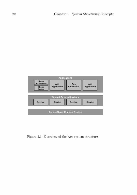
22 Chapter 3. System Structuring Concepts
Applications
Shared System Services
Service
Active Object Runtime System
Service Service Service
OberonSystem
AosApplication
AosApplication
AosApplication
OberonApplications
Figure 3.1: Overview of the Aos system structure.

3.4. Dynamic Loading 23
make use of the Oberon for Aos subsystem, which is an emulation ofthe Oberon system that allows most Native Oberon applications to becompiled and run without change on Aos (cf. 7.1).
The system modules are layered on an abstraction level, but noton a functional level. This means that a lower layer will never relyon abstractions supplied in a higher layer, but could rely indirectly onfunctionality supplied there. For example, the runtime system providesan abstract module loader interface, which can be implemented in theservices layer, with the help of a file system and disk driver locatedthere. In this way the core of the system is kept small and flexible.
As is common in extensible systems the layering is not strict (in thesense that a higher layer may only rely on abstractions supplied by theimmediately lower layer), and therefore higher layers may use or extendabstractions supplied on any lower layer. For example, application mod-ules may import and use public modules in the runtime system directly,without having to go through modules of the services layer. Similarly, adevice driver can communicate directly with its hardware device usinglow-level language facilities. By keeping the system layers relatively flatand open, the ‘multiple layers of inefficiency’ syndrome of strictly lay-ered systems is avoided. Although buffering and batching of operationscan improve throughput in such systems, the latency of operations arealways adversely affected by the many layers they must pass through.
The whole module hierarchy is open-ended, i.e., system services andapplication programs are simply modules that extend the system’s mod-ule hierarchy.
3.4 Dynamic Loading
In Aos, as in the Oberon system, there is no concept of a pre-linkedexecutable program. Instead, all modules are dynamically loaded intomemory when they are first used.
As a module typically depends on functionality exported from othermodules, all required lower-level modules are loaded automatically whena higher-level module is loaded. If a required module is already presentin memory, the existing instance is reused. Thus module instances areautomatically shared between the modules depending on them. Thismakes a significant contribution to the low storage requirements of thesystem, as each module is only present once in memory and in the file

24 Chapter 3. System Structuring Concepts
system.Modules can be unloaded from memory when no longer required.
While a module remains loaded in memory, its global variables repre-sent its state, which can be used for communication between differentprocedure invocations and processes. Therefore, module unloading isnot performed automatically by the system, but can be done underprogram control, or manually by the user.
The ability to dynamically load modules is indispensable for a flexi-ble extensible system, as it allows extensions to the system to be loadedat runtime.
3.5 Service Modules
A logical approach to design lean and flexible systems is to use a minimalsystem core or kernel that can serve as the basis for the additionalcomponents necessary to solve some specific problem [78].
An example of this is the microkernel design approach popularized inthe nineties, where a small system core provides only very basic supportfacilities like processes and interprocess communication (IPC), and otheroperating system functionality is provided by application-level serversthat can be added and removed like normal user applications [119]. Thisdesign also makes it possible to develop and test interchangeable systemcomponents independently.
In microkernel systems, the servers are implemented as processes inseparate address spaces, and their clients communicate with them viaIPC facilities, e.g., synchronous message passing or remote procedurecalls. In early microkernels, this overhead led to performance problems,which were mitigated by later designs [46]. However, even with low-latency and high-bandwidth IPC, the overhead of marshalling parame-ters into serial form for cross-address-space communication remains.
In response to this, newer monolithic kernel designs such as So-laris [64] and Linux allow ‘modules’ to be loaded dynamically into thekernel. Although this solves the performance problems associated withapplication-level servers, it does not provide all the advantages. Load-able modules execute in a specialized environment and can not be devel-oped and tested as normal user-level applications. Additionally, mod-ules are not cleanly supported in the languages used in these kernels.
In Aos, the active object runtime system is used as a small system
3.6. Plugin Modules and Objects 25
core, and additional system functionality is added by service modules inthe system services layer. This mirrors the basic idea of the microkerneldesign, but avoids the overhead. Service modules are accessed by theirclients via normal procedure and method calls. Compared to microker-nels and monolithic kernels, this lightweight approach promises muchbetter performance and reduced complexity.
Although service modules conceptually belong to a separate systemlayer, they are completely normal Active Oberon modules that exporttheir server functionality for clients to import and use. As dynamicloading is used, the service modules required by an application are au-tomatically loaded and started when it is loaded.
3.6 Plugin Modules and Objects
Plugin modules are used in Aos to further improve the flexibility andleanness of the system. A plugin module is used in a situation wherea standard system interface is identified that can be implemented indifferent ways.
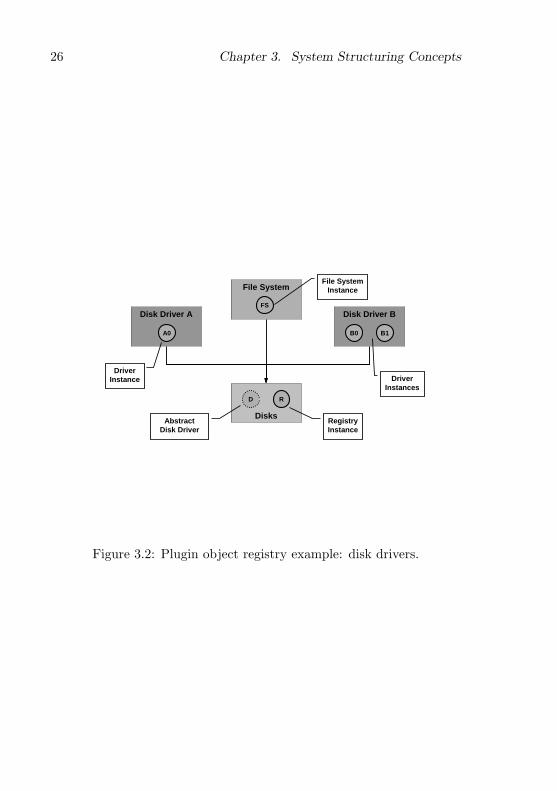
A typical example are device drivers for a specific class of devices.In this case an abstract interface is defined for the class of devices,and several different plugin driver modules are implemented for spe-cific members of the class. The abstract device interface is defined ina module of its own and clients that use the device import this mod-ule. In a given system configuration the appropriate driver modulesare ‘plugged in’ dynamically into the interface module. In this way theservice module and the device modules are indirectly coupled via theinterface module (see figure 3.2).
A plugin module is usually responsible for several instances of theobject class it manages and therefore instantiates one or more pluginobjects. For example, a device driver plugin will instantiate one objectfor every instance of the device present in the system.
Unlike normal modules, plugin modules are not imported directly bytheir clients. Instead, a client imports the interface module that definesthe interface implemented by the various plugin modules. A pluginmodule also imports this interface module and registers itself there.
For this purpose, a plugin registry object is defined by the system.Each interface module exports an instance of this object, which is acollection of plugin objects and serves as a registry where plugin objects
26 Chapter 3. System Structuring Concepts
Disk Driver B
B0 B1
File System
Disk Driver A
Disks
A0
R
Driver Instance
RegistryInstance
FS
File System Instance
D
AbstractDisk Driver
Driver Instances
Figure 3.2: Plugin object registry example: disk drivers.
3.7. Commands 27
that implement the specific interface are registered by plugin modules,and retrieved by client modules.
Figure 3.2 is an example of how the registry service is used. The fourshared rectangles represent modules. The Disks module is the interfacemodule for disk drivers, which defines an abstract disk driver object.This object is extended in concrete disk driver implementation modulesA and B, which implement drivers for two classes of disk devices. A filesystem implementation module imports the Disks module and accessesa disk indirectly using the interface defined by the abstract disk driverobject. It does not import any of the disk driver modules directly.
The shaded circles in the figure represent object instances. The Disksmodule exports a single global variable instance of a plugin registry ob-ject (R), which serves as a collection of all disk driver plugin objects.Each disk driver implementation module (A and B) implements a diskdriver as an extension of the abstract disk driver object (D). One in-stance of such an object is created for every physical disk (A0, B0, B1)and registered with R. A file system object finds the driver object forthe disk containing its data from the registry.
3.7 Commands
Aos uses a more general implementation of the Oberon system’s com-mand concept. Commands are indirectly related to system structuringas they provide a mechanism for loose coupling of modules. For ex-ample, plugin modules are normally instantiated via commands, whilesome plugin objects, e.g., file system implementations, are created bygenerator commands.
The Oberon system’s commands are simply exported parameterlessprocedures that are dynamically callable using the module loader. Theyare used mainly for two purposes: initiating actions in the Oberon userinterface and generating object instances.
The Oberon user interface uses commands as the principle meansfor the user to initiate actions. The text viewer system translates amouse click on a text string of the form M.P into a call of commandprocedure P in module M . If the module is not yet present in memory,it is loaded. Once a module is in memory, its global variables can beused for communication between subsequent command invocations. Forexample, the display space data structure containing all open viewers

28 Chapter 3. System Structuring Concepts
(windows) is rooted in a global variable of the Viewers module. Com-mands operate on this global data which, together with data structureson the heap, represents the state of the user interface.
In the persistent object kernel of Oberon, a generator is a commandthat creates an instance of a specific object type. Since command pro-cedures can be called dynamically using the module loader, they allowa client module to call procedures without statically importing theirdefining module. In fact, the name of the command could be generatedat runtime and the command need not even exist at the time the clientmodule is compiled. Thus, generators provide a way to generate objectinstances from modules that are not directly imported. This is essentialwhen creating modules that manipulate heterogeneous extensible datastructures, e.g., the rich text system of Oberon.
In both these uses of commands in Oberon, global variables are usedfor communication between the invoker of a command and the commanditself. In the case of a command initiated by a mouse click, the contextof the M.P text string is stored in a well-known global variable, where Pcan fetch it to scan its parameters. In the case of generator commands,the generated object instance is assigned to another well-known globalvariable, where it is fetched by its consumer.
The Oberon command concept can not be applied directly in a mul-tiprocessing system like Aos. The global variables used for communica-tion between a command and its invoker are shared resources that haveto be protected from concurrent access by different processes.
In Aos, the notion of a command is generalized so that it is no longera parameterless procedure. Parameters can now be passed to commandsdirectly and they can return results directly, without resorting to globalvariables or an explicit locking protocol. A parameterized command inAos is defined as a procedure with a generic pointer parameter and ageneric pointer return value. This requires only a small change to thecompiler, the module loader and boot linker.
With this simple change, commands turn into a powerful mechanismfor realizing independent modules that can work together nonetheless.They are used to instantiate plugin modules and to generate pluginobjects without directly importing them, an essential feature in a leanextensible system. They are also used by a user to initiate actions,and unlike Oberon commands, they work reliably even if actions areinitiated in parallel, e.g., by a batch command processing facility to run

3.7. Commands 29
commands in the background using active objects.

30 Chapter 3. System Structuring Concepts
Chapter 4
Active Object Runtime Design
In this chapter the design decisions that were made in the developmentof the active object runtime system (Aos kernel) are discussed. Thenext chapter describes the details of the runtime system modules.
4.1 Runtime Requirements
Programs in compiled languages are translated by a compiler into ma-chine code that can be executed directly by a machine. Many constructsin these languages, such as assignments, loop statements and expres-sions, can be translated directly into machine code, but some morecomplicated constructs, such as dynamic object allocation, can not becompletely translated and require the assistance of a runtime system,which consists of subroutines and data used by the translated code toperform its functions. Some languages, e.g., Modula-2 and C, requirealmost no runtime support, and other languages, e.g., Active Oberonand Java, have high-level constructs that require more runtime support.
The primary design requirement for the Aos kernel is to be a com-plete runtime environment for the Active Oberon language (cf. 2.2). Thekernel is tuned for this language, even though it is it is capable of sup-porting other comparable languages, e.g., Java (cf. 8.3.2). Mechanismsrequired by other language environments, but not by Active Oberon,can be provided in the form of plugins, to avoid encumbering the kernelunnecessarily.
A runtime system is usually based on the facilities provided by the
31

32 Chapter 4. Active Object Runtime Design
Application
Runtime System
Operating System
Hardware
Application
System Services
Runtime System
Hardware
Figure 4.1: Runtime system location (traditional left, Aos right).
underlying operating system, but in the case of Aos the runtime systemresides on the bare machine (see figure 4.1). Therefore, two secondaryrequirements are that it must implement the required runtime supportnatively in terms of the underlying hardware, and it must support theprogramming of operating system services. Most operating system ser-vices like file systems and communication can be programmed directlyin Active Oberon, but device drivers require some interface to the un-derlying hardware for I/O operations and interrupt handling.
The next section describes the active object language support andsection 4.3 describes the facilities for programming native operatingsystem services.
4.2 Active Object Language Support
The Aos kernel is mainly intended as a runtime system for Active Obe-ron and similar languages. The facilities it supplies for this purpose

4.2. Active Object Language Support 33
are:
• Modules and dynamic loading.
• A simple object model with type extension (single-inheritance sub-classing) and type-bound procedures (methods).
• Object memory management using garbage collection.
• Lightweight processes, locks and general process synchronization.
4.2.1 Modules and Dynamic Loading
Dynamic loading of modules plays an important role in an extensiblesystem (cf. 3.4). To execute a module, its source code has to be trans-formed to machine code in memory. For this, three main options areavailable (ignoring interpretation):
1. The compiler generates an object file containing machine codeand meta-information, which is loaded into memory, relocated andlinked with other modules by a module loader.
2. The compiler generates an object file containing intermediate codethat is compiled into memory on-the-fly at load time [37].
3. The source code is syntax-checked and stored in tokenized formand then compiled on-the-fly at load time [63].
As each of the options has its own advantages and disadvantages, theruntime system should not exclude any of them in advance. Therefore,we separate the module loading mechanism into two parts: a basic partthat handles the location and recursive loading of modules, and a pluginpart that creates the runnable machine code in memory. The plugincould simply load a compiled object file, or it could perform on-the-flycompilation.
The plugin part of the module loader uses the basic part to obtaininformation about procedures, types and variables exported from mod-ules, so that it can link the newly loaded module with the modulesthat it imports. In a similar way, the plugin links the module with anyruntime facilities that it may require.

34 Chapter 4. Active Object Runtime Design
4.2.2 Object Model
Active Oberon is an object-oriented language and programs written init are mainly concerned with creating and manipulating objects. Theunderlying object-oriented characteristics of Active Oberon, supportedby the runtime system, are summarized here.
An object is an anonymous, dynamic instance of an object type (i.e.,class in object-oriented terminology), referenced by at least one objectreference variable, which is a typed pointer variable that stores a refer-ence to an object compatible with its type.
An object contains fields, which are named variables nested in thescope of the object and store its state. An object also has methods, whichare named procedures nested in the object scope that can manipulatethe state of the object.
Object types can be extended (single inheritance) by defining a newobject type as an extension of an existing one. The fields and methodsof the existing object are inherited by the new object. A method ofthe new object type can override a method of the same name in theexisting object type. In this case the method in the existing objectis replaced by the new implementation in the new object, which musthave the same signature. It is possible to perform a supercall from anoverriding method to the overridden method. A type test can be usedto test whether an object reference variable points to an object of aspecific type.
An object is allocated explicitly (e.g., with the Active Oberon NEWprocedure), but is deallocated automatically by the system when noreferences to it exist any more. In practice, the deallocation can bedelayed until the system’s garbage collector has completed its next fullcycle.
As these characteristics are essentially the same as in Oberon-2 [71],this part of the runtime system is based on the ETH Oberon systems,specifically Native Oberon.
4.2.3 Process Model
The major addition in the Active Oberon object model is the objectbody, which specifies the inherent activity of an active object. As itdoes not make much sense to execute the activities of active objects

4.2. Active Object Language Support 35
sequentially, the runtime system must provide concurrent processes forthis purpose.
To ensure that hundreds or even thousands of active objects canbe created, the processes should be suitably lightweight. This can beensured by only associating a small process descriptor and a stack forthe local variables of the executing program with a process. Processesshould not be used as domains or containers for resource allocationpurposes and they all share the same global linear address space. Whenaiming for a minimal runtime system, every concept added that mayincrease the system complexity should be considered carefully.
Scheduling issues. In a multiprocessor system, different processesshould obviously be assigned to different processors, but each proces-sor can execute only one process at a time, and typically there maybe many more runnable active objects than processors. In a genericpopulation of possibly independent active objects, it is likely that theprocesses of some objects will perform computations for extended pe-riods of time, without any natural reason to pause their execution. Ifmore such processes exist than there are processors available, they willblock the execution of others in the population. Unless further measuresare taken, only some processes will make progress during these extendedperiods of time. Therefore, some form of pseudo-parallelism, in which aprocessor interleaves the execution of several processes, is required.
A possible solution is to require computationally intensive active ob-jects to release the processor voluntarily by calling a runtime procedurefrom time to time. However, this solution is not satisfactory; experiencewith tasks in Oberon have shown that this is difficult to coordinate, es-pecially when active objects make use of other objects to perform theirwork. It can also be inefficient, as releasing the processor too oftencauses unnecessary overhead, and releasing it too seldom restricts theprogress of other active objects.
A better solution is to use time-slicing, i.e., let the system automat-ically preempt long-running processes by setting a timer to interruptthem. In this way the system is in control of the frequency of pro-cess switches and the active object programmer does not have to worryabout releasing the processor.
To make the Aos runtime system viable for realtime environmentsand responsive in interactive use, a facility must be provided to allow

36 Chapter 4. Active Object Runtime Design
more important processes to run before less important ones. Thereforethe assignment of relative priorities to processes is foreseen. At anytime, the processes executing will have a priority not lower than that ofall other runnable processes.
There are basically two approaches to scheduling multiple proces-sors: either each processor is responsible for its own scheduling, or oneprocessor is responsible for scheduling on all the processors [112]. Thefirst approach is preferred for its simplicity, symmetry and scalability.
Synchronization. Runtime support for active object process syn-chronization has two aspects: the exclusive regions of active objectshave to be protected by a locking mechanism, and the await statementrequires condition management, which is the periodic evaluation of syn-chronization conditions specified by the programmer (cf. 2.2).
The compiler and runtime system use locks (binary semaphores) toensure that the exclusive regions of an object are entered by at mostone process at a time. Every object (or module) instance is allocatedone lock, which is acquired by a process entering the exclusive region,and released when the process reaches the end of the region. A processis not allowed to recursively acquire the same lock.
For well-behaved synchronization, the compiler and runtime systemenforce the rule that an await statement must always be enclosed in anexclusive region. When await is executed, the current process must holdthe lock of the enclosing object (or module), or a runtime error occurs.When the condition is found false and the current process has to bedelayed, the lock is released first. Likewise, the object state modificationthat establishes the condition being waited on must be made in anexclusive region of the same object. This obligation is the responsibilityof the programmer and is not automatically checked. It is also assumedthat the conditions are free of unwanted side effects, but this is notenforced by the system.
The conditions that delayed processes are waiting on have to beevaluated periodically by the runtime system. Under the assumptionthat the relevant object state is only changed in an exclusive region, itsuffices to evaluate the conditions related to a specific object instanceevery time a process exits the relevant exclusive region.
In the case where a process exits an exclusive region, and the systemfinds that the condition of a waiting process is now true, the lock is
4.2. Active Object Language Support 37
not released, but instead transferred atomically to the process that waswaiting before. That process is then activated and continues to run assoon as it is scheduled on some processor. In this way, if one processestablishes a condition B, the woken process can safely assume thatB still holds when its await statement terminates (e.g., in figure 2.3,when Put establishes n 6= 0, Get can safely assume this still holds whenits await statement terminates). In other words, the following proofrule holds for await, where I is the invariant of the associated exclusiveregion:
{I} AWAIT(B) {I ∧B}
It is of course possible for several processes to be awaiting conditionsin the same object context. When a process exits the relevant exclusiveregion, the runtime system evaluates all the waiting conditions in se-quence until the first true condition has been found, and the associatedprocess is reactivated. It is not necessary to evaluate the rest of theconditions immediately, as they will be checked when the reactivatedprocess exits the exclusive region.
Context switches. When implementing pseudo-parallelism, it hasto be decided when a processor will perform a context switch from oneprocess to the next. There are a few situations where this can be donenaturally, because the running process has no useful work to do anymore. These are called synchronous context switches, because they aresynchronized with the actions of the running process. They occur whenthe running process:
1. attempts to enter an exclusive region held by another process,
2. executes an await statement with an unsatisfied condition, or
3. terminates.
A synchronous context switch is always the result of a call to theruntime system by the running process itself. This knowledge can beused to optimize these context switches by only saving the relevantsubset of the processor state, similar to what is done with the coroutinelibrary implementation in Modula-2 [131].
Time-slicing and process priorities provide two more reasons for aprocessor to be switched away from a running process, namely:
38 Chapter 4. Active Object Runtime Design
1. it has executed continuously for an extended period of time andhas used up its time slice, or
2. a higher-priority process becomes ready to run.
These two conditions, together with the three listed earlier, representall possible reasons for a context switch to occur.
When a timer interrupt expires the time slice of the running process,or a device interrupt enables a higher-priority process to run, the resultis always an asynchronous context switch, because the running processis preempted at an arbitrary location during its execution. In this casethe full state of the process has to be saved.
In contrast, a context switch due to a higher-priority process becom-ing available can be either synchronous or asynchronous. Such a switchoccurs when a process P that has been waiting on a lock or condition issuddenly able to run again, because some other process Q has releasedthe associated lock. There are two situations to consider in this case.First, if Q has a lower priority than P , the situation is handled likea synchronous context switch, because Q has performed a system callto release the lock. The process Q is preempted, and process P startsrunning on the same processor. Conversely, if Q does not have a lowerpriority than P , it must continue to run on the same processor, and Pmust be scheduled to run on another processor that is currently exe-cuting a lower-priority process. The second case is more complicatedto handle than the first, because it involves finding another processorrunning a lower-priority process, and preempting the process runningon that processor.
4.2.4 Runtime System Calls
The support for active objects can be implemented by a handful of pro-cedures exported from the runtime system: CreateProcess, Lock, Unlockand Await (cf. 5.9.3, 5.10 and 5.11). The compiler inserts normal calls tothese procedures in the object code, and the module loader links thesecalls with the runtime modules.
To instantiate an active object, the compiler generates a CreatePro-cess call that creates a process to execute the object body. In the case ofActive Oberon, active objects are instantiated with the NEW standardprocedure call. This is compiled into: a call to allocate the object’s

4.3. Native System Facilities 39
memory, a call to the object’s initializer, if any, and a call to create theprocess that will execute the body. Due to type extension, an objectmay have several active bodies, so a process is created for each of these.
When compiling exclusive regions, the compiler generates a Lockcall at the start of the region, and an Unlock call at every point controlleaves the region. For both calls, the self reference of the relevant objectis passed as the only parameter.
The await statement is supported by the Await system call, whichhas three parameters. The first is a reference to a function that evalu-ates the associated condition being waited on, the second specifies thestack context of the condition and the last is the self reference of therelevant object. The condition function is a separately-callable functionprocedure generated by the compiler for every await statement. Thisfunction has one parameter that specifies the context of the statementand returns the result of the condition evaluation as a boolean value.It can be called by the runtime system when the condition needs to beevaluated.
4.3 Native System Facilities
The active object runtime system realizes the language support de-scribed above natively on the hardware without any operating systemunderneath. For example, memory management is handled directly bythe runtime system kernel.
In fact, facilities are provided for implementing operating systemservices on the runtime system. This allows a lean and efficient systemto be configured that excludes some or all of these services. For example,it would be possible to use the kernel to build a lean active object-based control application that requires little or no operating systemsupport like a file system, a viewer system or user interface. In this way,control applications can be written in a language with active objects andgarbage collection and compiled to run almost directly on the hardware,with just the small active object runtime system underneath.
A native system must include its own operating system services anddevice drivers and the latter require an interface to the underlying hard-ware. The Active Oberon language provides some low-level features forthis purpose in the SYSTEM module (cf. 2.2.4), but this must be com-plemented by runtime system support.
40 Chapter 4. Active Object Runtime Design
Section 4.3.2 describes the Aos device driver model, which treatsdevice drivers as normal programs, and section 4.3.3 describes the inter-rupt handling model, which maps interrupts to Active Oberon languageconstructs like procedures and objects.
4.3.1 Memory Management
One of most basic tasks of an operating system is the management ofmemory. In Aos, this is the responsibility of the active object runtimesystem itself, as no underlying operating system is used. Put simply,the task is to implement the Active Oberon built-in procedure NEWfor the allocation of heap objects (active objects, normal objects anddynamic arrays). This includes the allocation of stack space for the localvariables of processes. No explicit deallocation procedure is foreseen; thesystem has to deallocate unused memory automatically, with some formof garbage collection.
The Native Oberon system serves as an example of how simple mem-ory management can be made. Virtual addresses are mapped identi-cally to physical addresses (except for one area that is left unmappedto trap NIL pointer references), and the resulting memory is dividedinto two areas, one for the system stack, and one for the heap. Thismodel simplifies device driver programming, as drivers can use virtualaddresses directly when performing direct memory access (DMA). Asall allocated memory is physically contiguous, drivers can work directlyon data shared with their client programs, without having to resort tocopying or complicated page mapping.
The design of Aos aspires to this ideal, but there are complicatingfactors. Below, some assumptions are stated and justified, and the re-sulting issues discussed. An implicit assumption in an extensible system(cf. 3.1) is that a single global address space is used, allowing data tobe shared directly between different parts of the system. This does notnecessarily exclude the use of different protection domains [84].
No object copying. Since Aos is intended for inherently cooperativeenvironments (cf. 3.1), it is assumed that the range checking and typesafety provided by the language are sufficient tools for maintaining sys-tem integrity, and that separate address spaces are not required for thispurpose.
4.3. Native System Facilities 41
The runtime system and system services sometimes need to bypassthe type system and the associated range checks, to access memory di-rectly. Judicious use of this technique in performance-critical parts ofthe system (e.g., device drivers and system libraries) can improve per-formance significantly, which can be justified, even given the additionalrisk of compromising system integrity and reliability. But, when thetype system is bypassed, the objects being operated on must remain atthe same virtual address during the whole operation.
A copying (or compacting) garbage collector needs to copy objectsto different virtual addresses during their lifetime. As long as the objectis accessed only in a type-safe way via explicitly declared pointer vari-ables, the runtime system and compiler can cooperate to ensure accessconsistency.
Copying garbage collectors have three apparent advantages [55].Firstly, allocations are cheap; secondly, fragmentation is avoided; andthirdly, the cache locality of data is possibly improved. However, copy-ing data around all the time seems wasteful, and the advantages are notconclusive. Zorn found that a generational mark-and-sweep collectorcan be more effective than a copying collector [138], and Boehm et al.have developed a very effective conservative mark-and-sweep collector,which reduces fragmentation with a two-level allocation scheme [13, 14].
Under these considerations, the use of a copying garbage collector isexcluded to simplify the design.
No demand-paged virtual memory. A virtual memory system usesdemand paging to back up parts of the virtual address space to secondarystorage. This means that virtual pages are sometimes not physicallypresent, and do not always map to the same physical pages. The NEWprocedure initializes a pointer variable with the virtual address of thememory allocated. Normally, the actual physical location of the memoryis not relevant to a program; it could be allocated on non-contiguousphysical pages, or paged out to secondary storage.
As an exception to this, device drivers performing DMA have specialmemory allocation requirements. The memory used has to be physicallypresent at the same location during the whole transfer and, in mostcases, there are also special alignment and contiguity restrictions. Inspite of this, device drivers in Aos should ideally be completely normalprograms, and should be able to act directly on the data shared with
42 Chapter 4. Active Object Runtime Design
their clients without special allocation procedures or additional copying.For this reason, and based on the experience with Native Oberon, it
was decided not to consider virtual memory in the system design. Al-though virtual memory allows programs to handle more data directly,the sometimes severe and unpredictable performance degradation is un-satisfactory. Virtual memory presents a false abstraction, because of theextreme latency of accessing paged-out memory. It is better to handledata on secondary storage explicitly, by using files. As an aside, theavailability of apparently unlimited virtual memory on some operatingsystems seems to encourage wasteful design.
The assumptions above allow the arrangement of the heap as a singleshared area in the virtual address space, mapped directly to physicalmemory as in Native Oberon. Were it not for the requirements of pro-cess stack management (and to a lesser extent, NIL reference checking),it could even be worth considering the elimination of the virtual-to-physical mapping completely.
Process stacks. The Native Oberon stack model can unfortunatelynot be used for Aos, as it must be able to manage the process stacksof hundreds of concurrently running active objects, not just one. Thestacks must also be able to grow dynamically, since for general program-ming tasks it is not possible to predict in advance how large they shouldbe.
Conceivably, a process stack could be allocated as a contiguous blockin the normal heap, with compiler-generated stack overflow checks (inthe absence of a hardware stack limit register). When a stack overflowsit could be reallocated by allocating a larger area, copying the existingstack, and modifying all references to the stack, including the dynamicand static link chains. This would require detailed meta-information de-scribing the location of reference parameters, as local variables can alsobe referenced indirectly. It would also require integration with the gar-bage collector, which has to scan the stacks for roots. Such an ambitiousscheme requiring close cooperation between the compiler and runtimesystem would probably be fraught with unforeseen complications.
Brinch Hansen described an interesting stack allocation scheme forparallel programs, which interleaves fixed-sized stack segments from dif-ferent processes in the heap. Unfortunately the solution is “not realis-tic for an operating system, which allocates an unbounded number of

4.3. Native System Facilities 43
segments, most of which are unique to particular user jobs” [21]. On amultiprocessor, the scheme also requires two lock and unlock operationsper block activation, which would be an intolerable overhead.
Another option for managing process stacks is to allocate a fixedarea of the virtual address space for each stack. Initially, only a smallpart of the area, typically one page, is allocated physically. When aprocess uses more than the allocated space, a page fault occurs andthe system allocates more physical pages to the stack. This solution iseasy to integrate with the garbage collector, which has to scan the stackareas (possibly conservatively) for root pointers.
Direct memory access in device drivers again presents a problem.Since the physical pages of a virtual stack are not necessarily contiguous,a driver can not always perform direct memory access on stack pages.However, this problem can be avoided by allocating buffers in the heapinstead. This solution is not entirely satisfactory, but workable, becauseDMA buffers tend to be large, and it is therefore better not to allocatethem on a stack with limited size.
The virtual stacks organization has the disadvantage that the max-imum size of a stack is limited a priori. Depending on the size of theaddress space, it might also place an unsatisfactory limit on the totalnumber of process stacks. Nonetheless, this organization was chosenfor Aos, because of its straightforward implementation and compilerindependence.
4.3.2 Device Driver Model
Unlike closed systems (cf. 3.1), where device drivers normally reside inthe kernel and have special restrictions, the aim in Aos is to make devicedrivers as similar to normal programs as possible. A device driver is justa normal module that exports some service functionality abstracting adevice and uses low-level facilities of the language and kernel to com-municate with the hardware. Specifically, it shares the same addressspace with its client modules and can therefore work directly on clientparameters without any additional data copying.
The fact that device drivers share the same address space with userprograms does not have any intrinsic effect on the stability of the system.Even on systems where device drivers reside in a separate address space,an error in a device driver can cause a system crash, as they use low-level

44 Chapter 4. Active Object Runtime Design
facilities like DMA that bypass the normal processor checks. What ismore important is that device drivers have a simple and unexceptionalprogramming model, so that errors are less likely.
The Oberon system uses a polling I/O model. A device driver foran input device provides a polling procedure and a read procedure.The Oberon main loop or a user program polls to determine if inputis available, and, if so, it calls the read procedure, which will returnimmediately. For output, a write procedure is provided that sends thegiven data and returns when done. This model is simple and efficient ina single-process system, but inappropriate for a multiprocessing system.If a process is polling a device continually, it is wasting processing timethat could be used by other processes to do useful work.
Instead of polling, Aos device drivers should provide blocking in-terfaces, where an I/O request to a driver suspends the client processuntil it can be satisfied. While the requesting process is suspended,other processes can perform useful work. This kind of interface can berealized by encapsulating the driver in an object, and using the awaitstatement to block the client process in the object until it can continue.This usually requires synchronization with an interrupt from the device.
4.3.3 Interrupt Handling Model
An interrupt is usually used by a device to signal the completion ofsome I/O operation, and must therefore be routed to the relevant devicedriver.
Low-level interrupt handling. The Native Oberon system uses aprocedure call model for handling interrupts. A device driver can reg-ister an Oberon procedure as an interrupt handler for a specific inter-rupt. When the interrupt occurs, the kernel saves the processor stateand calls the registered procedure. All interrupts are disabled for theduration of the procedure, and when it returns, the processor state isrestored so that execution continues from the interrupted location. In-terrupt handlers may re-enable interrupts, and can then be interruptedby higher-priority interrupts, according to the priority model defined bythe interrupt controller.
The polling and read procedures provided by a device driver com-municate with the interrupt handler via shared global variables. These
4.3. Native System Facilities 45
procedures typically disable interrupts for a short time while accessingthe shared variables, to ensure that no conflicting concurrent accessesare made by the interrupt handler.
The procedure call model has very little overhead. Some minimal‘glue’ code is needed to save the processor state and call the registeredprocedure, and afterwards acknowledge the interrupt and restore theprocessor state. On Ceres Oberon this code is generated inline by thecompiler for even less overhead (no kernel involvement during the in-terrupt). This is not done here, in order to decouple the compiler andruntime system more, thereby simplifying the support for other lan-guages than Active Oberon.
At a low level, Aos too uses this simple procedure call model forhandling interrupts. However, interrupt procedures are restricted inwhat they can do. For example, they are not allowed to enter exclusiveregions or use await statements, as they are not independent processesthat can be suspended. To treat device drivers as first-class objects, ahigher-level interrupt handling concept is required.
Exception handling. At the processor level, exceptions (i.e., traps)are similar to interrupts, but are caused by errors during the execu-tion of a processor instruction (e.g., a division by zero), or by specialexception-generating instructions (e.g., software interrupt instructions).An exception usually signals a failure in the currently running program,therefore a typical response is to terminate the current process.
In Native Oberon, all exceptions are handled by the system, notby user programs. The default action is to display a trap text with asymbolic stack traceback showing the context of the exception. Thenthe stack is reset and the Oberon main loop is restarted, thereby abort-ing the current command or task. Although it is possible for a userprogram to install an alternative system-wide exception handler, thedefault handler is used in most cases.
Since the Active Oberon language has no general exception handlingfacilities, e.g., an equivalent to the try-catch construct of C++, the run-time system does not have to provide complicated exception handlingsupport. When an exception occurs, the kernel simply terminates thecurrent process, or restarts it if the SAFE modifier was placed on theactive object body that started the process (cf. 2.2.4).
To allow other language environments running on the kernel, e.g.,
46 Chapter 4. Active Object Runtime Design
Java, to handle their own exceptions, it suffices to allow each process toinstall an exception handling procedure, similar to an interrupt handlerprocedure. A plugin module that provides support for such a languagecan install a handler that gets control when an exception happens andcan unwind the stack or do whatever is necessary to handle it.
Active object interrupt handling. The higher-level interrupt han-dling mechanism referred to above is described here. It allows devicedriver objects to directly handle interrupts and synchronize with theirclients using exclusive regions and await statements.
Figure 4.2 shows the outline of a device driver object using thismechanism. The example driver is for a device that periodically pro-duces data and causes an interrupt to signal its availability. The inter-rupt handler reads the data from the device and stores it the object’sfields, where a client can fetch it using the Read method. This methoduses an await statement to wait until data is available.
The example object is an extension of a system-supplied abstractbase object InterruptHandler, which has a HandleInterrupt method over-ridden and implemented by the driver. The driver object registers toreceive interrupts by making a special system call in its initializer.
The implementation of interrupt handling is complicated by the factthat the same interrupt number can be shared by different devices. ThePCI bus standard [82], used in many modern system architectures, al-lows independent devices to share level-triggered interrupt lines. Thekernel must allow multiple processes to register for the same interrupt.When the interrupt occurs, all the registered handlers must be acti-vated, and only when the interrupt has been processed by all, can it beunmasked again. The device drivers must handle the resulting spuriousinterrupts gracefully.
To implement the high-level interrupt handling mechanism, the sys-tem provides an active object behind-the-scenes for every interrupt num-ber. When an interrupt occurs, the process of this object is scheduledto call the registered interrupt handler methods. It sequentially callsall the methods registered on the specific interrupt. The interrupt ismasked while these calls are being performed and after they have all re-turned, the interrupt is unmasked and the system process is suspendeduntil it is signalled again.
The high-level interrupt handling model described here was imple-
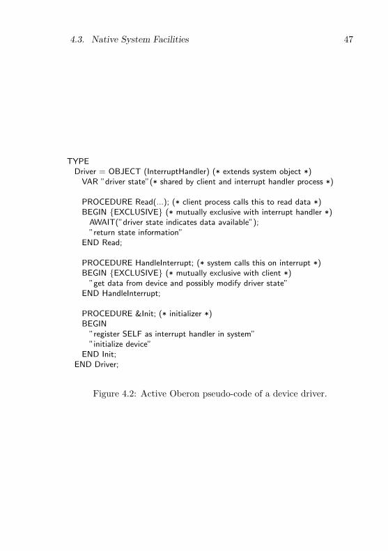
4.3. Native System Facilities 47
TYPEDriver = OBJECT (InterruptHandler) (* extends system object *)
VAR ”driver state”(* shared by client and interrupt handler process *)
PROCEDURE Read(...); (* client process calls this to read data *)BEGIN {EXCLUSIVE} (* mutually exclusive with interrupt handler *)
AWAIT(”driver state indicates data available”);”return state information”
END Read;
PROCEDURE HandleInterrupt; (* system calls this on interrupt *)BEGIN {EXCLUSIVE} (* mutually exclusive with client *)
”get data from device and possibly modify driver state”END HandleInterrupt;
PROCEDURE &Init; (* initializer *)BEGIN
”register SELF as interrupt handler in system””initialize device”
END Init;END Driver;
Figure 4.2: Active Oberon pseudo-code of a device driver.

48 Chapter 4. Active Object Runtime Design
mented in the Aos kernel. The outline of an alternative model that wasnot implemented, is presented in appendix C.
Chapter 5
Multiprocessor Runtime
Implementation
This chapter describes the native implementation of the active objectruntime system (the bottom layer in figure 3.1) on the Intel IA-32 sym-metric multiprocessor (SMP) architecture.
5.1 Multiprocessor Implementation Issues
Target architecture. The active object runtime system was firstimplemented on the Intel IA-32 SMP architecture realized in the In-tel P6-family of processors — the Pentium Pro, Pentium II and Pen-tium III [51]. This architecture was selected as we aimed to show how alean but powerful multiprocessor system can be developed for relativelylow-cost multiprocessor machines available today. The implementationalso works with other IA-32 processors like the Pentium and the Pen-tium 4, but does not use the new multiprocessor features introducedon the latter. It would be relatively easy to adapt it for i386 and i486embedded processors.
The Intel architecture (see figure 5.1) is typical for multiprocessorswith up to eight processors. Each processor is tightly coupled with itsprimary and secondary cache, which connects it to the shared memorysubsystem via the system bus. Each processor has an advanced pro-grammable interrupt controller (APIC), which connects it to a specialbus for interrupt delivery and interprocessor communication. This bus
49
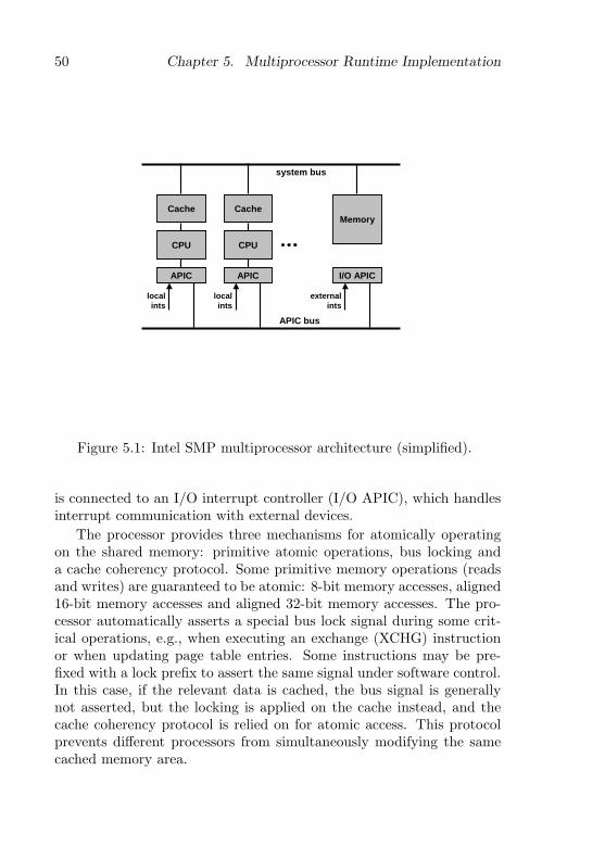
50 Chapter 5. Multiprocessor Runtime Implementation
Cache
CPU
APIC
Cache
CPU
APIC
Memory
I/O APIC
localints
localints
APIC bus
system bus
externalints
Figure 5.1: Intel SMP multiprocessor architecture (simplified).
is connected to an I/O interrupt controller (I/O APIC), which handlesinterrupt communication with external devices.
The processor provides three mechanisms for atomically operatingon the shared memory: primitive atomic operations, bus locking anda cache coherency protocol. Some primitive memory operations (readsand writes) are guaranteed to be atomic: 8-bit memory accesses, aligned16-bit memory accesses and aligned 32-bit memory accesses. The pro-cessor automatically asserts a special bus lock signal during some crit-ical operations, e.g., when executing an exchange (XCHG) instructionor when updating page table entries. Some instructions may be pre-fixed with a lock prefix to assert the same signal under software control.In this case, if the relevant data is cached, the bus signal is generallynot asserted, but the locking is applied on the cache instead, and thecache coherency protocol is relied on for atomic access. This protocolprevents different processors from simultaneously modifying the samecached memory area.

5.1. Multiprocessor Implementation Issues 51
Memory ordering model. The local processor caches significantlyimprove program performance, but also complicate programming due totheir imposition of a possibly non-intuitive, relaxed memory ordering.The memory ordering model is an artefact of the buffering and cachingimplementation of the processor’s memory interface [33, 69]. Put simply,the interaction of shared memory reads and writes from the same ordifferent processors may lead to unexpected results.
It should be noted that the memory ordering model is only relevantto user programs when processes interact without acquiring critical sec-tion locks, e.g., when a shared variable is accessed without protecting itwith exclusive regions. This kind of access often occurs in performance-critical software, where avoiding a locking operation in the common casecan provide great benefit.
Our approach to this problem is to simply expose the memory order-ing model of the P6-family processors, since this model is still relativelyintuitive. Our compilers align 8-bit, 16-bit and 32-bit variables so thatthey can be accessed atomically. If Aos is ported to other multiproces-sor architectures with a more relaxed memory ordering, e.g., the IA-64architecture, an approach where the compiler and runtime system co-operate to present a stronger model may be more appropriate [126].
Interrupt controllers. The local APIC built into every processor(see figure 5.1) is responsible for routing interrupts to it. These con-trollers are connected to a shared I/O APIC that routes interrupts fromI/O devices to the processors. The routing can be static so that an in-terrupt is always routed to a specific processor, or it can be dynamic, sothat interrupts are routed to the lowest-priority processor. For this case,every local APIC has a processor priority register that can be updatedby software.
The APIC can be used by any processor to initiate an interrupt onany subset of the processors. This interprocessor interrupt facility isused by the runtime system to synchronize different processors, e.g.,during garbage collection.
Another case where interprocessor interrupts are used is in the syn-chronization of the paging structures shared by all processors in Aos.When a page is unmapped from the virtual address space, (e.g., whena process stack is deallocated), an interrupt is sent to every processorrequesting it to clear its translation lookaside buffer (TLB).

52 Chapter 5. Multiprocessor Runtime Implementation
Memory
Interrupts
Boot
Processors
Kernel
Active
Heap
Locks
Out
Modules
Figure 5.2: Aos runtime system module structure.
The APIC can also be programmed to generate periodic interruptsto the local processor. This facility is used by the runtime system toimplement time-slicing and statistical profiling.
5.2 Runtime Module Decomposition
Figure 5.2 shows the module structure of the runtime system and ta-ble 5.1 shows the responsibilities of the various modules. The implemen-tation of the kernel was split into many small modules to make it moreunderstandable, even though it could probably have been made smallerby combining all kernel functionality in one module as in the Oberonsystem. This also has the consequence that some kernel modules (e.g.,Heap) export implementation details. Where possible, modules abovekernel level should only import the top-most kernel module.
The bottom two modules (Boot and Locks) can be seen as an ex-tension of the processor’s instruction set with facilities needed in the

5.2. Runtime Module Decomposition 53
Module Responsibility
Kernel Portable kernel interfaceProcessors Multiple processorsActive Active objectsModules Modules and typesInterrupts Low-level interruptsHeap Heap and garbage collectorMemory Virtual address spaceOut Serial console output (debugging)Locks Fine-grained locksBoot Boot loader and environment interface
Table 5.1: Aos runtime system module responsibilities.
implementation of the runtime system.The Boot module acts as interface between the runtime system, the
boot loader and the firmware, providing access to the machine’s hard-ware configuration information. This is required since the hardwareenvironment can be quite diverse and complex. It also assigns everyprocessor in a multiprocessor system a unique sequence number, whichcan be used to index per-processor data structures, and provides someprimitive atomic operations.
The Locks module provides locks for the protection of runtime datastructures. As the critical sections in the runtime system are relativelyshort and do not contain await operations, the locks are implementedwith busy-waiting.
The Out module provides console output and is used mostly fordebugging purposes. During system startup some progress informationis written to the console. This is invaluable to find startup problems.
The virtual address space and object storage management aspects ofmemory management are implemented in the Memory and Heap mod-ules, respectively. The Memory module initializes the virtual addressspace using the paging facilities of the processor and manages page-level allocation and deallocation. It provides procedures for accessingmemory-mapped devices and for allocating and deallocating processstacks and heap memory. The Heap module manages the heap, which isused to allocate objects, dynamic arrays and untyped blocks of memoryusing Active Oberon’s NEW standard procedure call. Deallocation of

54 Chapter 5. Multiprocessor Runtime Implementation
unused objects is performed automatically by a mark-and-sweep gar-bage collector.
The Modules module is responsible for modules, types and com-mands. It implements the dynamic loader algorithm, while the actualloading of an object file is handled by a plugin.
Three modules are responsible for implementing active objects andinterrupt handling: Processors, Active and Interrupts. The Interruptsmodule manages the interrupt controller and maps interrupts into Obe-ron procedure calls. The Active module is the heart of the runtime sys-tem. It implements lightweight processes for active objects, schedulesthe processes, manages the object locks and synchronization conditionsand implements active object-based interrupt handling and timing. TheProcessors module implements multiprocessor support. It is responsi-ble for interprocessor communication and booting additional processors,when present. It also provides a periodic timer facility used for accu-rate timing in device drivers and for time-slicing, which is essential onsingleprocessor machines.
The Kernel module exports primitive atomic operations, fine-grainedtiming and finalization operations (cf. 5.6). In some cases it also re-exports some functionality from the rest of the runtime system, wherethis can be done portably and with negligible performance loss. Whenhigher-level modules need kernel services, they should import only thismodule, as far as possible, to be less dependent on a specific runtimeimplementation. It is intended as the only module in the runtime systemwith a portable interface that can be considered stable, even when theimplementation of the runtime system changes. This gives a systemimplementor the freedom to change the interfaces of any other runtimemodules, without adversely affecting many higher-level modules.
The following sections of this chapter describe the modules of thekernel in a bottom-up fashion.
5.3 Interfacing with the Environment
The first piece of software to get control when an Intel IA-32 machineboots is the firmware (i.e., BIOS) provided by the manufacturer. Thisprogram performs some initial testing and initialization of the proces-sors, memory and boot devices, and proceeds to boot the installed oper-ating system kernel. It provides a level of manufacturer-independence,

5.3. Interfacing with the Environment 55
allowing the kernel to boot on machines with different motherboards,memory configurations and boot devices.
The modules of the Aos kernel are statically linked into a boot file,which is written to a hard disk or other boot device, together with aboot loader. After initialization, the firmware loads the boot loaderinto memory and starts executing it. The Native Oberon boot loader isused, which performs the following tasks:
1. Set the segment registers and stack for a simple 16-bit executionenvironment which allows us to use firmware services like the bootdevice driver.
2. Read the boot file into memory and check its consistency.
3. Query the firmware for some hardware information and store thisin memory for later use.
4. Set up a simple 32-bit execution environment, move the boot fileto its final location at address 1M and start executing it.
Boot module. The first module in the Aos kernel that gets controlis the bottom-most module, called Boot. It is responsible for low-levelinitialization and interfacing with the firmware, which makes availablesome information about the hardware environment, e.g., the number ofprocessors available. Information which is not reliably provided by thefirmware, e.g., the total memory size, is computed here.
The module exports some functions for use in the rest of the kernel,the most important of which is the processor ID function, which re-turns a unique sequence number for each processor it executes on. Thisnumber is used to index arrays containing per-processor data. Alsoexported are an atomic test-and-set operation and atomic versions ofthe INC, INCL and EXCL standard procedures of Oberon, used whenoperating on shared data.
When this module gets control, the processor that has been electedas boot processor is running, and the other processors are disabled.After this module has initialized, the boot processor continues executingthe body of the next-higher kernel module, and so on until the Processorsmodule which finally boots the other processors (cf. 5.12).

56 Chapter 5. Multiprocessor Runtime Implementation
5.4 Protecting Runtime Data Structures
The data structures of the runtime system have to be protected fromconcurrent access by different processes. On a multiprocessor system,processes running on different processors can make parallel calls to theruntime system. Additionally, if processes are allowed to be preemptedwhile they are executing in the runtime system, the data structures haveto be protected against pseudo-concurrent accesses, which happen whena process switch occurs in a critical section.
Examples of such data structures are the queues and arrays men-tioned in section 5.9.2, but also the structures of the memory manager,interrupt handling, module management, and other parts of the runtimesystem.
On a singleprocessor system, the critical sections can be protectedby simply switching off interrupts during their execution. This disablesprocess switches, ensuring that the current process has exclusive accessto the data during the critical section. The Oberon system uses thissolution to protect data structures shared between the Oberon processand interrupt handlers in device drivers. This is not sufficient in a mul-tiprocessor environment, because different processors can access shareddata even when they are running with interrupts disabled.
Spin locks. Critical sections in a multiprocessor environment can beprotected by binary semaphores implemented with busy-waiting — alsoknown as spin locks [7]. Most modern processors have primitive atomicinstructions such as ‘test-and-set’ or ‘exchange’ which can be used toimplement spin locks. The lock is implemented as a boolean variable.The acquire operation sets the lock variable to true, and at the sametime tests its existing value. If the value was true, the operation isretried (and the value remains true). Otherwise, the operation finisheswith the value set to true, indicating that the lock is held, and that thecritical section may be entered. The release operation at the end of thecritical section simply sets the lock value to false, allowing other acquireoperations to succeed.
Spin locks as described above can interact with interrupts to producedeadlocks. If a critical section is interrupted, and the interrupt handlerattempts to acquire the lock that protects this critical section, it willwait forever. This is avoided by disabling interrupts during critical

5.4. Protecting Runtime Data Structures 57
sections.Another reason for disabling interrupts during critical sections is to
avoid interrupts that could cause the process that is currently execut-ing in the kernel to be preempted and rescheduled on another proces-sor. This is important as kernel critical sections often manipulate per-processor data structures and therefore assume that the same processorexecutes the whole critical section.
When protecting critical data structures, there is a trade-off in de-ciding how large a critical section to protect. Using few locks reducesthe complexity and makes it easier to avoid deadlock, but also reducesthe potential parallelism. Using many locks improves the potential par-allelism, but makes it more difficult to avoid deadlocks. The lattersolution may also have a higher overhead due to processes having toacquire and release more locks.
As an example, the runtime system could use one single lock toprotect all its data structures. This implies that only one process canexecute in it at any time, which could severely restrict parallelism. Abetter option is to have a lock for every data structure, but partitioningthe critical sections is not straightforward when the data structures —or the interactions between them — are non-trivial.
A middle road taken in Aos is to structure the runtime system as sev-eral modules, each of which manages a few related data structures, andto use a single lock for each module. This makes it relatively straight-forward to show that an implementation is deadlock-free.
Locks module. The handling of spin locks is concentrated in theAos kernel module called Locks, which provides two kinds of spin lock.The first kind is used to protect global kernel data structures and thesecond kind is used to protect the header fields of an active object(cf. 5.10.1). The difference between the two kinds is that the first alsodisables interrupts during the critical section and therefore needs tokeep track of the nesting level of locks. The second kind of lock is astraightforward lightweight spin lock which can not be nested.
The following strategy is used to avoid deadlock in the kernel: Asfar as possible, only a single lock is held at a time. For the cases wheremore than one lock is required simultaneously, the locks are acquired ina fixed order, so that no hold-and-wait cycles can occur. To simplify theissue of lock ordering, only one lock is used per module, to protect all

58 Chapter 5. Multiprocessor Runtime Implementation
the shared global variables of the module at once. This lock is acquiredat critical entry points to the module, and released at exit points. Thereare three kinds of entry points: exported procedures, local proceduresthat are registered as upcalls in other modules (e.g., interrupt handlerprocedures) and overridden methods of objects from other modules (rarein the kernel). Procedures that are not module entry points do not needto acquire the lock, as they are always called from other procedures thatare entry points. If we further ensure that no locks are held when anupcall is performed, it suffices to order the locks according to their levelin the module hierarchy. Thus the acyclic module import structure isused to order the locks and avoid deadlock, as in the THE system [29].
To evaluate the cost of locking, especially the decision to use onlyone lock per module, the locking module optionally accumulates thefollowing statistics on the use of the individual locks: the number oftimes a specific lock was acquired, the mean and maximum time thelock was waited for and held, and the variance of these times.
5.5 Memory Management
Section 4.3.1 presented the design decisions behind the Aos virtual ad-dress space organization and concluded that a single shared virtual ad-dress space containing the heap and process stacks should be used, withthe heap area mapped identically to the physical address space. Inthis section we first summarize the memory management options ofthe IA-32 architecture and then show how the virtual address space ismapped to the physical address space.
IA-32 memory management options. The IA-32 architecture [53]supports segmentation and paging. Paging can be switched off, butsegmentation is always enabled. The processor translates 48-bit logicaladdresses via segmentation to 32-bit linear addresses, which are thenoptionally translated via paging to 32-bit or 36-bit physical addresses.Pages can be 4KB, 2MB or 4MB big, and can be mapped to physicalmemory or marked as not-present. To speed up address translation,page-table entries are cached in code and data translation lookasidebuffers (TLB caches).
A logical address consists of a 16-bit segment selector, specifyingsome segment, and a 32-bit offset into the segment. The segment selec-
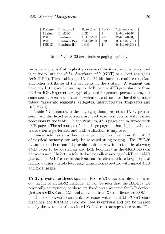
5.5. Memory Management 59
Feature Introduced Page sizes Levels Address sizePaging Intel386 4KB 2 32-bit (4GB)PSE Pentium 4KB/4MB 2/1 32-bit (4GB)PAE Pentium Pro 4KB/2MB 3/2 36-bit (64GB)PSE-36 Pentium III 4MB 1 36-bit (64GB)
Table 5.2: IA-32 architecture paging options.
tor is usually specified implicitly via one of the 6 segment registers, andis an index into the global descriptor table (GDT) or a local descriptortable (LDT). These tables specify the 32-bit linear base addresses, sizesand other attributes of the segments in the system. A segment canhave any byte-granular size up to 1MB, or any 4KB-granular size from4KB to 4GB. Segments are typically used for general-purpose data, butsome special segments describe system data structures (local descriptortables, task-state segments, call-gates, interrupt-gates, trap-gates andtask-gates).
Table 5.2 summarizes the paging options present on IA-32 proces-sors. All the listed processors are backward compatible with earlierprocessors in the table. On the Pentium, 4KB pages can be mixed with4MB pages. The advantage of using large pages is that single-level pagetranslation is performed and TLB utilization is improved.
Linear addresses are limited to 32 bits, therefore more than 4GBof physical memory can only be accessed using paging. The PSE-36feature of the Pentium III provides a direct way to do this, by allowing4MB pages to be located on any 4MB boundary in the 64GB physicaladdress space. Unfortunately, it does not allow mixing of 4KB and 4MBpages. The PAE feature of the Pentium Pro also enables a large physicalmemory, using a triple-level page translation structure with mixed 4KBand 2MB pages.
IA-32 physical address space. Figure 5.3 shows the physical mem-ory layout of an IA-32 machine. It can be seen that the RAM is notphysically contiguous, as there are fixed areas reserved for I/O devices(between 640KB and 1M, and above address X) and firmware ROM.
Due to backward compatibility issues with old IBM PC/AT-classmachines, the RAM at 512K and 15M is optional and can be maskedout by the system to allow older I/O devices to occupy these areas. The
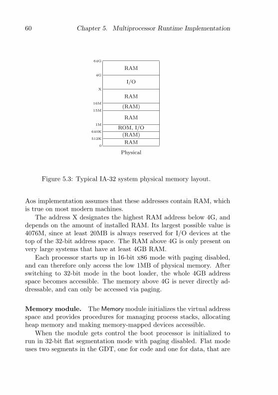
60 Chapter 5. Multiprocessor Runtime Implementation
64G
RAM4G
I/O
X
RAM16M
(RAM)15M
RAM1M
ROM, I/O640K
(RAM)512K
RAM0
Physical
Figure 5.3: Typical IA-32 system physical memory layout.
Aos implementation assumes that these addresses contain RAM, whichis true on most modern machines.
The address X designates the highest RAM address below 4G, anddepends on the amount of installed RAM. Its largest possible value is4076M, since at least 20MB is always reserved for I/O devices at thetop of the 32-bit address space. The RAM above 4G is only present onvery large systems that have at least 4GB RAM.
Each processor starts up in 16-bit x86 mode with paging disabled,and can therefore only access the low 1MB of physical memory. Afterswitching to 32-bit mode in the boot loader, the whole 4GB addressspace becomes accessible. The memory above 4G is never directly ad-dressable, and can only be accessed via paging.
Memory module. The Memory module initializes the virtual addressspace and provides procedures for managing process stacks, allocatingheap memory and making memory-mapped devices accessible.
When the module gets control the boot processor is initialized torun in 32-bit flat segmentation mode with paging disabled. Flat modeuses two segments in the GDT, one for code and one for data, that are

5.5. Memory Management 61
4GMappings
3.75G
Stacks3G
32M
6Heap1M
640K
4K
Firmware/Devices
Page Heap (Mapped)
Unmapped0
Virtual
4G
Devices
32MPage Heap
?
6Heap1M
640K
4K
Firmware/Devices
Page Heap (Mapped)
Page Heap0
Physical
Figure 5.4: Address space organization (32MB RAM shown).
both based at address 0 and encompass the whole 4GB linear addressspace. All the segment selector registers are set to these segments, andin effect segmentation can now be ignored.
Figure 5.4 shows the main areas of the virtual address space, whichare mapped to the physical address space using paging.
The heap starts at 1M and grows upwards. Virtual pages are mappeddirectly to physical pages, which simplifies device drivers that performdirect memory access (cf. 4.3.1).
The stack area contains all process stacks and has a fixed size andlocation close to the top of the address space. When a process stack isallocated, a fixed part of the stack area is allocated to it. Initially, onlyone page is physically allocated, but when page faults occur in this area,additional pages are allocated. Arbitrary physical pages from the pageheap described below can be mapped to the stacks, and the pages arenot necessarily physically contiguous. The virtual address ranges forthe stacks are managed using a fixed-sized block allocator implementedwith a bitmap.
The mapping area maps in parts of the physical address space con-taining memory-mapped devices and is at the top of the address space.
The low area below 1M is a mixed bag. It is mapped directly to
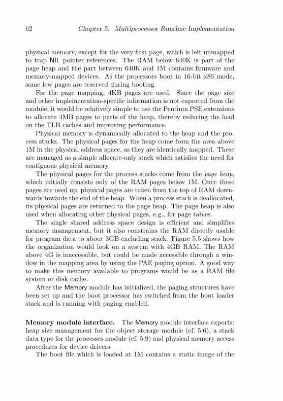
62 Chapter 5. Multiprocessor Runtime Implementation
physical memory, except for the very first page, which is left unmappedto trap NIL pointer references. The RAM below 640K is part of thepage heap and the part between 640K and 1M contains firmware andmemory-mapped devices. As the processors boot in 16-bit x86 mode,some low pages are reserved during booting.
For the page mapping, 4KB pages are used. Since the page sizeand other implementation-specific information is not exported from themodule, it would be relatively simple to use the Pentium PSE extensionsto allocate 4MB pages to parts of the heap, thereby reducing the loadon the TLB caches and improving performance.
Physical memory is dynamically allocated to the heap and the pro-cess stacks. The physical pages for the heap come from the area above1M in the physical address space, as they are identically mapped. Theseare managed as a simple allocate-only stack which satisfies the need forcontiguous physical memory.
The physical pages for the process stacks come from the page heap,which initially consists only of the RAM pages below 1M. Once thesepages are used up, physical pages are taken from the top of RAM down-wards towards the end of the heap. When a process stack is deallocated,its physical pages are returned to the page heap. The page heap is alsoused when allocating other physical pages, e.g., for page tables.
The single shared address space design is efficient and simplifiesmemory management, but it also constrains the RAM directly usablefor program data to about 3GB excluding stack. Figure 5.5 shows howthe organization would look on a system with 4GB RAM. The RAMabove 4G is inaccessible, but could be made accessible through a win-dow in the mapping area by using the PAE paging option. A good wayto make this memory available to programs would be as a RAM filesystem or disk cache.
After the Memory module has initialized, the paging structures havebeen set up and the boot processor has switched from the boot loaderstack and is running with paging enabled.
Memory module interface. The Memory module interface exports:heap size management for the object storage module (cf. 5.6), a stackdata type for the processes module (cf. 5.9) and physical memory accessprocedures for device drivers.
The boot file which is loaded at 1M contains a static image of the
5.5. Memory Management 63
4GMappings
3.75G
Stacks3G
32M
6Heap1M
640K
4K
Firmware/Devices
Page Heap (Mapped)
Unmapped0
Virtual
4.25G(Paged)
4GDevices
3.75GPage Heap
?3G
32M
6Heap1M
640K
4K
Firmware/Devices
Page Heap (Mapped)
Page Heap0
Physical
Figure 5.5: Address space organization (4GB RAM shown).
kernel modules in the same format as the heap managed by the heapmodule. This image forms the initial heap and the first procedure be-low returns its boundaries for the heap module. The second procedureallows the heap module to control the dynamic heap size. As input itaccepts the requested heap end address, and as output it returns thenew heap end address that was actually set.
PROCEDURE GetHeapAdr(VAR begin, end, first, free: LONGINT);PROCEDURE SetHeapEndAdr(VAR end: LONGINT);
For stack management, the following type and operations are ex-ported. A stack can be allocated or deallocated, and the virtual memoryallocated to a stack can be extended.
TYPEStack = RECORD
low, high: LONGINT (* stack boundaries *)END;
PROCEDURE NewStack(VAR s: Stack; VAR sp: LONGINT);PROCEDURE DisposeStack(VAR s: Stack);PROCEDURE ExtendStack(VAR s: Stack; adr: LONGINT): BOOLEAN;

64 Chapter 5. Multiprocessor Runtime Implementation
The first two procedures below allow a physical address range to bemapped into the virtual address space, or unmapped, respectively. Thelast function returns the physical address corresponding to a virtualaddress range, for direct memory access operations. If the specifiedaddress range is not physically contiguous (e.g., in the stack area), itreturns −1.
PROCEDURE MapPhysical(phys, size: LONGINT; VAR virt: LONGINT);PROCEDURE UnmapPhysical(virt, size: LONGINT);PROCEDURE PhysicalAdr(virt, size: LONGINT): LONGINT;
The module also exports some initialization procedures used whenbooting other processors. The first procedure returns a low page con-taining a bootstrap loader for subsequent processors, and the secondprocedure is called by each processor to initialize its paging unit.
PROCEDURE InitBootPage(start: PROCEDURE; VAR phys: LONGINT);PROCEDURE InitMemory; (* initialize paging *)
5.6 Object Storage Management
Heap module. The Heap module is responsible for managing ob-ject allocation and garbage collection in a contiguous growable block ofmemory obtained from the Memory module. Rather than implement acompletely new allocation and garbage collection algorithm, it was de-cided to adapt that of Native Oberon, which is in turn based on earlierETH Oberon versions. For Aos, the algorithm was extended to handleactive objects and abstract root objects. The unsafe finalization mech-anism was replaced by a safer one (p. 67). The allocator was adaptedto share memory with the stack allocator. The heap management isimplemented in a separate module to make explicit the interface be-tween it and the rest of the runtime system and thereby simplify laterreplacement by another algorithm.
Oberon garbage collection overview. Ceres Oberon [134] uses amark-sweep garbage collector [55]. The mark phase of the garbage col-lector is implemented without a recursion stack by using a pointer re-versal algorithm [107]. The basic algorithm is essentially the same inmost ETH Oberon versions, but later implementations lifted some re-strictions and added support for object-orientation.
5.6. Object Storage Management 65
Ceres Oberon has two kinds of heap blocks: one for records allocatedwith NEW and one for untyped memory allocated with SYSTEM.NEW.Both kinds of block have a one-word header, which contains a mark bytefor the garbage collector, and either the size of the block or a pointer tothe type descriptor for a record. Such a pointer is also called a type tag,and is used to generate efficient type tests, and to find type informationduring garbage collection. The type descriptor contains the size of therecord, the tags of its base types and the offsets of pointer fields inthe record. It is allocated as an untyped heap block, therefore it doesnot need a meta-type descriptor. The fields of the type descriptor areused in type tests and in the garbage collector. As an implementationrestriction, dynamic arrays are allocated as untyped blocks and are notallowed to contain pointers.
Heeb and Pfister [85] describe an improved algorithm that uses thetype tag as an implicit mark byte. Templ [85] describes an extendedalgorithm that lifts the implementation restriction and allows dynamicarrays to contain pointers. Templ also developed a simple finalizationmechanism [120]. For Object Oberon [70] and Oberon-2 [71] the typedescriptor was extended to support type-bound procedures (i.e., virtualmethods). The resulting heap block layout of later Oberon implemen-tations is documented in [27, 117]. This was used with minor changesin Native Oberon.
As is mostly the case, the added functionality has a cost in terms ofadded complexity. In comparison with Ceres Oberon’s two kinds of heapblocks, Native Oberon has four [25], and their structure is somewhatmore involved:
1. Simple record block for dynamic records and objects.
2. Type descriptor block with meta-type descriptor for itself.
3. Array block for dynamic arrays containing pointers.
4. System block for dynamic arrays without pointers, module de-scriptors and untyped memory.
In Ceres Oberon, the garbage collector is invoked only from the mainloop, when it is known that there are no heap blocks that are reachableexclusively from local pointer variables. Thus, local pointer variables onthe stack can be ignored during the mark phase without risking dangling
66 Chapter 5. Multiprocessor Runtime Implementation
pointers, thereby simplifying the garbage collector. Unfortunately, thiscan lead to program failures due to an apparent lack of memory, whena command allocates a lot of temporary memory.
To solve this problem in a general way, later Oberon garbage collec-tor implementations also consider local pointer variables on the stackas roots. To find such variables without additional stack layout descrip-tors, they scan the stack (and the processor registers) conservatively tofind pointer candidates, and perform an additional sweep operation toconfirm which candidates point to actual heap blocks. In this way thegarbage collector can be invoked at any time — also from the allocationprocedure when the free lists are empty. For Aos, this ability to invokethe garbage collector at any time is essential, as there is no steady statein which all process stacks are known not to contain pointer variablesexclusively anchoring heap blocks.
Adding active objects. From the allocation perspective, an activeobject is similar to an Oberon-2 dynamically allocated record with type-bound procedures, except that it requires additional system data inevery instance to manage locking and conditions. Therefore it is feasibleto take the Oberon garbage collector and adapt it to support activeobjects. The main problem is how to extend the heap blocks of recordsto include the additional data. In Eamon [30], this is done by havingthe programmer declare every active object as an extension of a system-supplied base object that contains the necessary fields. For Aos this isconsidered too inflexible, since it would not be possible to extend anexisting non-active object to make it active. In an object frameworkthat supports active objects, every base object would have to be declaredactive, incurring system overhead on every instance.
The solution chosen in Aos is to define a new heap block thatprepends the additional system information to a normal record block.The block is formatted so that it meets the alignment requirements of arecord block. This allows a non-active base object to be extended at alater time (perhaps in a different module) with an active body, and stillremain compatible with its extensions. Type tests can be compiled inexactly the same way as before. The details of the new block are shownin appendix B.
5.6. Object Storage Management 67
Adding abstract root objects. The garbage collector finds all livedata blocks in the heap by starting at the root pointers and exhaustivelytraversing all pointer links. All blocks that are not part of the transitiveclosure computed this way are unused and can be added to the free listfor reallocation. For the traversal the location of root pointers andthe location of pointers in the data blocks have to be known. Thismeta-information is contained in type descriptors, module descriptorsand process descriptors. The type descriptors define where pointers arelocated in data blocks, the module descriptors define the location ofglobal pointer variables, and the process descriptors contain the stackdescriptors used to locate local pointer variables.
In Aos, the concern of locating root pointers is removed from theHeap module by using abstract root objects. Module descriptors andprocess descriptors declared in higher-level modules are extensions ofthis object. When the garbage collector finds such an object in theheap, it calls its FindRoots method to obtain root pointers contained inthe object. In the case of a module descriptor this returns the globalpointer variables and in the case of the process descriptor, the stack ofthe process is scanned for pointer candidates. This mechanism decou-ples the garbage collector from the module and process descriptor datastructures, simplifying the implementation of other language environ-ments on the kernel.
When the garbage collector is initiated, the root pointer of the mod-ule list is passed to it. This is sufficient to trace all reachable datastructures as all other modules are reachable via the module list, andall processes are reachable via the scheduler data structures rooted inglobal pointer variables and active objects in the heap.
Finalization. Finalization is a mechanism that allows a user-definedprocedure to be called when an object is deallocated by the garbage col-lector [55]. Finalization is not required often, but when it is required,it is essential [50]. It is useful to create state-reduced module inter-faces, e.g., a file system module that does not require files to be closedexplicitly.
Finalization is useful in cases where garbage collected objects man-age external resources. It is then desirable to free the external resourcesassociated with an object once the object is deallocated. As the garbagecollector can not in general know the nature of the external resource, a
68 Chapter 5. Multiprocessor Runtime Implementation
suitably general mechanism must be provided.Native Oberon supports finalization of objects using Templ’s algo-
rithm [120]. An object reference and associated finalization procedurecan be registered with the garbage collector, which adds it to a speciallist of checked objects. When the garbage collector finds that a checkedobject is no longer reachable (except from the list), it removes it fromthe list, and calls the finalization procedure, passing a reference to theobject. The object is not deallocated immediately, as a reference to itstill exists. If the finalization procedure does not re-anchor the object,it will be collected in the next cycle.
In some cases a module needs to assign names to the objects thatit manages (e.g., file objects in a file system module). When a clientrequests an object by name, the same object reference must be returnedwhen the same name is requested multiple times. In Oberon this isimplemented by linking the objects together in a global collection usinguntraced pointers, which are pointers that are ignored completely bythe garbage collector. The objects are also registered for finalization.Subsequently, when a client no longer has a pointer to an object, thefinalization procedure of the object gets called, and the module canremove it from the global collection.
Although this technique is simple to use and implement, it is subtleand if incorrectly used can lead to dangling references — errors thatimpact the stability of the whole system and are notoriously difficult todebug. It is therefore desirable to provide a finalization mechanism inAos that does not depend on untraced pointers.
For the automatic management of named collections of objects theAos kernel provides the finalized collection object type, which managesa collection of arbitrary objects with automatic removal of otherwiseunreachable objects. Objects can be added to such a collection, removedfrom the collection and enumerated. They are also removed implicitlyby the garbage collector when they are no longer reachable, except forthe links inside the collection itself. Additionally, when an object isadded, a finalization procedure can be associated with it, which getscalled when the object is no longer reachable. Finalized collections aresimilar to identity directories in ETHOS [118], except that they canstore arbitrary objects.
Unlike the Oberon system, the Aos garbage collector does not callthe finalization procedure directly, as this can lead to deadlocks when
5.6. Object Storage Management 69
the garbage collector is invoked while an application is holding someobject locks. Instead, a separate process is used to call the procedures,thereby avoiding this kind of deadlock.
It is important to understand the limits of finalized collections whenusing them. As unreachable objects in a finalized collection are onlydiscovered once a garbage collection cycle completes, it is possible thatthey remain in the collection for an indefinite amount of time. Trulyscarce resources should rather be managed with explicit allocation anddeallocation, even though it is less convenient and more error-prone.
Interaction with the page heap. The allocation algorithm in Aosis similar to that of Native Oberon, except in the case where it runsout of free memory. In Native Oberon a garbage collection is thenperformed, and the allocation retried once before failing. In Aos there isthe additional choice of extending the heap by allocating more memoryfrom the page heap shared with the process stacks (cf. 5.5).
Deciding whether to extend the heap or not is a difficult problemto solve in general. Due to the simplifying requirements that the heapmemory be physically contiguous and that a non-moving garbage collec-tor is used (cf. 4.3.1), once pages are allocated to the heap they can notbe returned to the page heap. Therefore we would like to avoid growingthe heap unnecessarily, to maximize the number of process stacks thatcan be allocated. On the other hand, if the heap is kept small, garbagecollection has to be performed more often, resulting in unnecessary over-head. The compromise made is that the heap starts small, and while itis less than 50% of the total memory size, it is expanded immediatelyon initial allocation failure. Once it has grown past this limit, it is onlyexpanded after attempting a garbage collection first. Once it has grownto 95% of the total memory size, it is not expanded any more. In thisway the system adapts dynamically to its workload.
A simpler alternative to the dynamic sharing of pages between theheap and stacks would be to allocate a fixed number of pages to eachrole. This was rejected in favour of the more dynamic solution describedabove, but in some applications, e.g., embedded systems, it might ar-guably be the better choice.
Garbage collection algorithm. The mark-sweep garbage collectionalgorithm of Aos, adapted from Native Oberon, is described here.
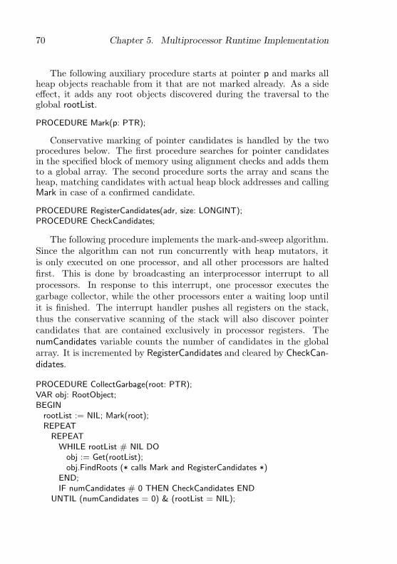
70 Chapter 5. Multiprocessor Runtime Implementation
The following auxiliary procedure starts at pointer p and marks allheap objects reachable from it that are not marked already. As a sideeffect, it adds any root objects discovered during the traversal to theglobal rootList.
PROCEDURE Mark(p: PTR);
Conservative marking of pointer candidates is handled by the twoprocedures below. The first procedure searches for pointer candidatesin the specified block of memory using alignment checks and adds themto a global array. The second procedure sorts the array and scans theheap, matching candidates with actual heap block addresses and callingMark in case of a confirmed candidate.
PROCEDURE RegisterCandidates(adr, size: LONGINT);PROCEDURE CheckCandidates;
The following procedure implements the mark-and-sweep algorithm.Since the algorithm can not run concurrently with heap mutators, itis only executed on one processor, and all other processors are haltedfirst. This is done by broadcasting an interprocessor interrupt to allprocessors. In response to this interrupt, one processor executes thegarbage collector, while the other processors enter a waiting loop untilit is finished. The interrupt handler pushes all registers on the stack,thus the conservative scanning of the stack will also discover pointercandidates that are contained exclusively in processor registers. ThenumCandidates variable counts the number of candidates in the globalarray. It is incremented by RegisterCandidates and cleared by CheckCan-didates.
PROCEDURE CollectGarbage(root: PTR);VAR obj: RootObject;BEGIN
rootList := NIL; Mark(root);REPEAT
REPEATWHILE rootList # NIL DO
obj := Get(rootList);obj.FindRoots (* calls Mark and RegisterCandidates *)
END;IF numCandidates # 0 THEN CheckCandidates END
UNTIL (numCandidates = 0) & (rootList = NIL);
5.7. Interrupts and Exceptions 71
CheckFinalizedObjectsUNTIL rootList = NIL;Sweep
END CollectGarbage;
The CheckFinalizedObjects procedure checks the reachability of ob-jects registered for finalization by traversing the list of registered objectsonce. If any unmarked objects are found, they are moved to anotherlist and subsequently marked (including their subgraphs). A separatefinalizer process is activated to call the associated finalization proce-dures after the garbage collector finishes. The Sweep procedure scansthe heap and adds all unmarked objects to the free list. It also clearsall mark bits.
The garbage collector is sensitive to memory caching issues, as ittraverses all reachable objects in the heap. Since only one processoris active during garbage collection, the kernel makes sure that it al-ways runs on the same processor. In some measurements this improvedthe performance of subsequent garbage collections with 35%, due tothe primed memory caches, even when long periods of time with otherprogram activity pass between the collections.
5.7 Interrupts and Exceptions
The IA-32 architecture supports three kinds of interrupts and excep-tions [53]:
External interrupts These are signals from external I/O devices orinterprocessor interrupts and timer interrupts from the APIC.
Software interrupts These interrupts are generated by special in-structions under program control.
Processor exceptions These interrupts are caused by errors duringinstruction execution. They are subdivided into three categories:faults (restartable exceptions), traps (resumable exceptions) andaborts (fatal exceptions).
External interrupts can be masked by the processor using the disableinterrupts instruction. I/O interrupts can also be masked individuallyby the interrupt controller. The other two kinds can not be masked.
72 Chapter 5. Multiprocessor Runtime Implementation
Interrupts module. The Interrupts module is responsible for drivingthe interrupt controller and the low-level handling of interrupts using theprocedure call model. Higher-level modules, e.g., device drivers usingactive objects, use the active object-based interrupt handling mecha-nism for I/O interrupts (cf. 4.3.3).
At this low level, all three kinds of interrupts described above aretreated equally. Handler procedures can be installed in the interruptvector table using the procedure defined below. A handler procedureis called when an interrupt occurs and gets full access to the processorstate at that time. It can also modify the state on return, which isuseful when implementing exception handling.
TYPEState = RECORD ... END; (* processor state *)Handler = PROCEDURE (VAR state: State);
PROCEDURE InstallHandler(h: Handler; int: INTEGER);
The state parameter contains a reference to the saved processor stateat the time of the interrupt. When the handler returns, this state isrestored in the processor. The stack pointer at the time of the interruptis part of the state and can be modified to return on another stack.The instruction pointer is also part of the state and can be modified toreturn to another location, e.g., to the terminate procedure to terminatethe process that caused an exception, or to a process-specific exceptionhandler.
External interrupts are masked by the processor for the duration ofthe handler procedure. Specific external interrupts can be unmaskedor masked permanently at the interrupt controller with the followingtwo procedures. These are later used to implement the higher-level I/Ointerrupt handling.
PROCEDURE EnableInterrupt(int: INTEGER);PROCEDURE DisableInterrupt(int: INTEGER);
During booting, every processor calls the following procedure to ini-tialize its interrupt handling mechanism. It loads the address of theinterrupt descriptor table into the interrupt descriptor table register.All processors share this table and handle interrupts the same way.

5.8. Modules, Types and Commands 73
PROCEDURE InitInterrupts; (* initialize interrupt handling *)
Exceptions are treated exactly like interrupts, except that they canprovide additional information on the processor state at the time of theexception, e.g., the kind of exception that occurred and the contentsof debugging registers. The following procedure returns the additionalinformation. The installed handler for an exception can modify the pro-cessor state, e.g., to cause the exception handler to return to a differentlocation and unwind the stack (cf. 4.3.3).
TYPEExceptionState = RECORD ... END; (* additional state *)
PROCEDURE GetExceptionState(VAR int: State; VAR exc: ExceptionState);
5.8 Modules, Types and Commands
Modules module. As in the Oberon system, the module called Mod-ules is responsible for modules, types and commands. It declares themodule descriptor and the list of loaded modules. It provides operationsto load and unload modules and to find existing modules. A modulecan register a termination procedure to be called when it is unloadedand when the system is shut down.
For module loading the recursive algorithm of Templ [120] is used,with the small modification that the actual creation of the module inmemory is performed by a plugin. This allows different object file for-mats to be supported (cf. 8.3.2), or for modules to be compiled on-the-fly. In configurations not requiring dynamic loading of modules (e.g.,some embedded systems), the plugin need not be installed.
The types contained in modules are described by type descriptors,which describe the size of a type and the location of methods and pointerfields. These are used by generated code when calling methods and bythe object allocator and garbage collector. Operations are provided tofind type descriptors by name or by tag, which can be used for debuggingand metaprogramming [120]. Type descriptors are generated by theHeap module, which also contains the garbage collector that uses thetype descriptors to locate pointer fields.
Modules can contain commands, which are exported procedures thatcan be called dynamically without explicitly importing them (cf. 3.7).
74 Chapter 5. Multiprocessor Runtime Implementation
Operations are provided to find commands by name. Aos commands aredistinguished from Oberon commands in that they can take a genericparameter and return a generic result.
5.9 Processes and Synchronization
Active module. The Active module is described in detail in the fol-lowing three sections. This module is responsible for everything directlyrelated to active objects: processes (cf. 5.9), object locking (cf. 5.10) andcondition management (cf. 5.11).
A process is used to execute the activity of an active object, ex-pressed by the program declared in its body. The process is createdwhen the active object is allocated, and terminates when the body ex-its. The process may call methods of the same or other objects andenter exclusive regions of those objects, where it competes with otherprocesses for entry to these regions. An object lock is used to protectthe exclusive regions of an object and allow only one process to enter aregion at a time. Condition management concerns the implementationof the await statement and the evaluation of the conditions expressedtherein.
5.9.1 Process States
A process can be in one of several states, and with every state (exceptTerminated) is associated a data structure which stores descriptors ofprocesses in that state. It follows that a process can only be in one ofthese data structures at any time — when it switches state it is alsomoved from one data structure to another. The states and all possibletransitions between them are shown in figure 5.6 and described below:
Ready This is the initial state of a process. It is ready to run andwaiting for a processor to be assigned to it, at which time it willmove to the Running state.
Running A process is in this state when it is running on one of theavailable processors. It leaves this state when it terminates, ispreempted, or starts waiting for a lock, condition or interrupt.
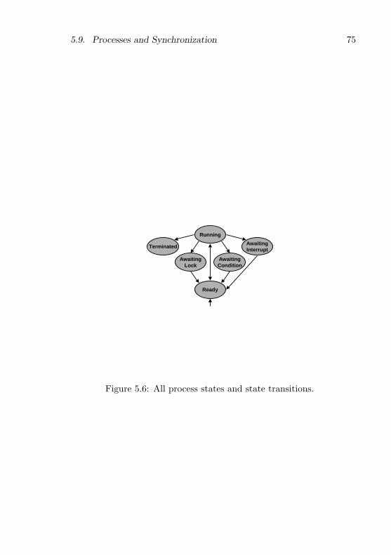
5.9. Processes and Synchronization 75
Running
Ready
AwaitingCondition
AwaitingLock
AwaitingInterrupt
Terminated
Figure 5.6: All process states and state transitions.

76 Chapter 5. Multiprocessor Runtime Implementation
AwaitingLock A process is in this state when it is waiting to acquirean object lock that is held by another process. When it eventuallyacquires the lock, it moves back to the Ready state.
AwaitingCondition A process is in this state when it is waiting fora condition to be made true by some other process. When thecondition is eventually found to be true by the runtime system,the process moves back to the Ready state.
AwaitingInterrupt A process (typically a device driver) is in thisstate when it is waiting for a specific interrupt to occur. Thisis similar to the previous state, except that the process will beenabled to run by an interrupt, and not the actions of anotherprocess (cf. 4.3.3). When it is enabled, it moves back to the Readystate.
Terminated This is the final state, which is entered when a process ter-minates. Terminated process descriptors are not in any program-defined data structure, but remain in the heap until they arecleaned up by the garbage collector.
5.9.2 Process Data Structures
This section describes the data structures used by the runtime systemto keep track of processes: ready queue, running array, lock queue, con-dition queue and interrupt array.
Process Descriptor A process descriptor is a small record containinginformation about a process. Its most important fields are shown below.
TYPEProcess = OBJECT ...
stack: Stack;state: ProcessorState;preempted: BOOLEAN;condition: Condition;conditionFP: ADDRESS;priority: INTEGER;obj: OBJECT;next: Process
5.9. Processes and Synchronization 77
END Process;
ProcessQueue = RECORDhead, tail: Process
END;
Every process has its own private stack, referenced by the stackfield, which is used to manage procedure calls and efficiently allocateand deallocate local variables.
When a process that was running on some processor is suspended,that processor’s state is stored in the state field, so that it can later berestored on the same or another processor when the process is sched-uled to run again. When the preempted field is set, the process hasbeen preempted and the full processor state is stored in the state field.Otherwise, only a partial copy of the processor state is stored.
The condition and conditionFP fields used for object condition man-agement are described in section 5.11.
The current priority of a process is defined by the priority integerfield, which can assume one of a fixed number of values, with lowervalues indicating lower priorities.
Every process has exactly one associated active object, which is ref-erenced by the obj field. This is set when the process is created and doesnot change afterwards. It is required only for the ActiveObject systemcall, which returns the associated active object.
A process descriptor can be in at most one queue, therefore a singlenext field is sufficient to implement queues of descriptors. A queue isrepresented by the ProcessQueue record, which references the first andlast descriptor in the queue.
Ready Queue The descriptors of processes in the Ready state arestored in a global ready queue. In fact, a separate first-in-first-out queueis used for each process priority level (three queues are shown at thebottom of figure 5.7):
VARready: ARRAY NumPriorities OF ProcessQueue;maxReady: INTEGER;
A process descriptor is entered into the ready queue in constant timeby indexing on its priority and adding it at the end of the relevant queue.
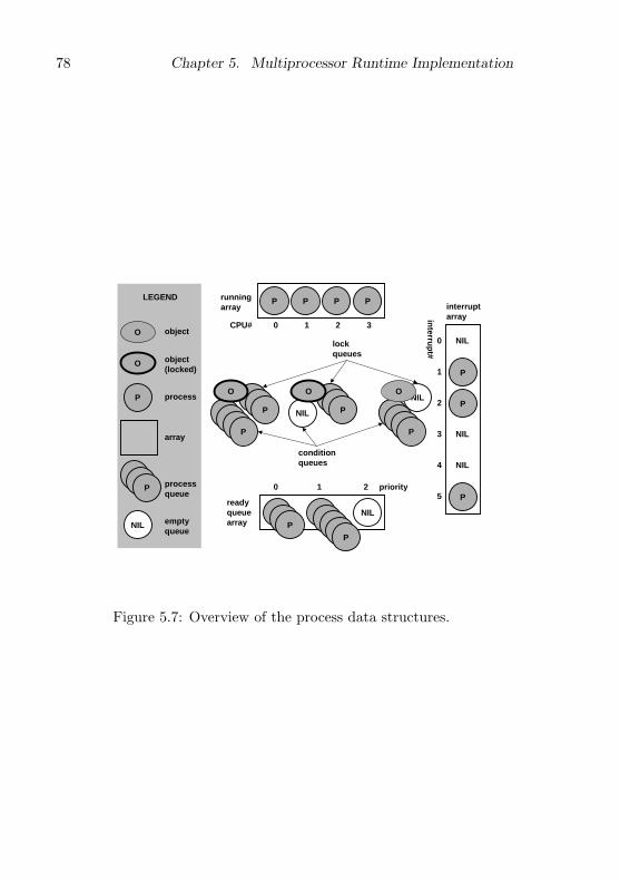
78 Chapter 5. Multiprocessor Runtime Implementation
NIL
NIL
NIL
P
P
P P P P
P
PP
P
P
0 1 2
interruptarray
0
2
1
3
5
4
0 21 3
runningarray
P
P
readyqueuearray
conditionqueues
lockqueues
NIL
NIL
NIL
O
P
object(locked)
process
array
P processqueue
LEGEND
CPU#
interru
pt#
priority
O object
emptyqueue
NIL
O O O
Figure 5.7: Overview of the process data structures.
5.9. Processes and Synchronization 79
Processes in the Ready state can not change their priority, so they arenever moved from one queue to another.
To select a new process to run, the queues are scanned from thehighest priority down until a non-empty queue is found and then thefirst process descriptor is removed from it. In the worst case all queueswould have to be scanned, so, to reduce the average search time, thesystem keeps track of non-empty queues in the maxReady variable, whichsatisfies the following invariant:
∀i : MinPriority ≤ maxReady < i < NumPriorities : Empty(readyi)
The full procedures to enter a process in the ready queue and selecta process from the ready queue are shown below. The Get and Put pro-cedures perform constant-time queue operations using the ProcessQueuetype and Process.next field. It is assumed that the relevant spin lock isheld when these procedures are called (cf. 5.4).
PROCEDURE Enter(p: Process);BEGIN
Put(ready[p.priority], p);IF p.priority > maxReady THEN maxReady := p.priority END
END Enter;
PROCEDURE Select(VAR new: Process; priority: INTEGER);BEGIN
LOOPIF maxReady < priority THEN new := NIL; EXIT END;Get(ready[maxReady], new);IF (new # NIL) OR (maxReady = MinPriority) THEN EXIT END;maxReady := maxReady-1
ENDEND Select;
The Select procedure has a priority parameter to specify the minimumpriority process that may be returned. This is used when the runtimesystem needs to select only process with the same or higher priority asthe current process, e.g., when timeslicing.
Running Array While a process is running on processor i, its de-scriptor is referenced by element i of the global running array (four
80 Chapter 5. Multiprocessor Runtime Implementation
processor elements are shown at the top of figure 5.7). The runtimesystem indexes this array using the ProcessorID function, which returnsa unique number for each processor it executes on.
VAR running: ARRAY NumProcessors OF Process;
The interplay between the running array and the ready queue is bestillustrated by the following procedure, which can be called by a processto yield the processor voluntarily to another.
PROCEDURE Yield;VAR id: INTEGER; new: Process;BEGIN
Acquire(Active);id := ProcessorID();Select(new, running[id].priority);IF new # NIL THEN
Enter(running[id]);SwitchTo(running[id], new)
ELSERelease(Active)
ENDEND Yield;
The Acquire and Release operations on the Active spin lock are usedto synchronize access to the shared data structures: the ready queue andrunning array. The Select and Enter procedures operate on the readyqueue. The SwitchTo procedure performs a context switch by storingthe processor state into its first parameter and loading the processorstate from the second parameter (similar to Modula-2’s TRANSFER). Itdoes not return immediately, but rather ‘returns’ to the new process’slast execution context. In all these procedures it is assumed that thecaller holds the Active spin lock and the SwitchTo procedure releases thelock as it switches to the new process.
As the Yield procedure is running in the context of the current pro-cess and using its stack, it is important that the Enter and SwitchTooperations execute indivisibly. This avoids the following race conditionwhich could occur if the spin lock were released between these two oper-ations: Process P executes Yield (or another scheduling procedure) onone processor. After Enter, but before SwitchTo, process Q running on
5.9. Processes and Synchronization 81
another processor also executes Yield, selects P to run and switches toit, whereby we end up with two processors executing P at the same timeon the same stack! By holding the Active spin lock during the Enter andSwitchTo operations we avoid this problem.
Lock Queue A process enters the AwaitingLock state when it startswaiting for some object’s lock to become available. Its process descriptoris added to the lock queue of the object being waited on. Every objectwith exclusive regions has such a lock queue, because processes canpotentially wait to enter its exclusive regions. When a process releasesthe lock of some object, the runtime system removes the first processdescriptor (if any) from the lock queue, cedes the lock to that process,and enters it in the ready queue (cf. 5.10). For illustration, figure 5.7shows three objects, the leftmost two of which have three processes eachwaiting in their lock queues, and the rightmost one with no waitingprocesses. A process descriptor moves from the running array to anawaiting lock queue when the process attempts to lock an object thatis already locked. As the process that has locked the object leaves theexclusive region, it hands the lock over to the first waiting process.When the process at the front of the queue receives the lock, it movesto the ready queue for its priority, from where it can proceed back tothe running array.
Condition Queue The AwaitingCondition state is entered when aprocess starts waiting for some condition to become true in an exclusiveregion of an object. Its process descriptor is added to the conditionqueue associated with the object containing the await statement. Ev-ery object with exclusive regions containing await statements has sucha condition queue. The queue is used by the runtime system when itneeds to re-evaluate conditions associated with an object. If a conditionis later found true, the associated process descriptor is removed fromthe condition queue and entered in the ready queue (cf. 5.11). For illus-tration, the middle object in figure 5.7 has no processes in its conditionqueue, and the other two objects have four waiting processes each. Themovement of a process descriptor through the condition queue is similarto that through the lock queue, except that the queue can be rotateddue to condition evaluation (cf. 5.11.3).

82 Chapter 5. Multiprocessor Runtime Implementation
Interrupt Array The descriptor of a process in the AwaitingInter-rupt state is stored in the global interrupt process array, which containsprocesses waiting on interrupts. When an interrupt occurs, the processis enabled and can then run to handle the interrupt (cf. 4.3.3). Forillustration, figure 5.7 shows 6 interrupt numbers, with three processeswaiting on interrupt number 1, 2 and 5, respectively.
No Process List A notable absence from the data structures de-scribed above is a global list of process descriptors. In fact, there is nosuch list that has to be updated when a process is created or terminates,which reduces space and time overhead. The described data structuresare the only places where process descriptors are stored by the runtimesystem, so if its descriptor is no longer in any of these structures, a pro-cess is terminated by definition. Of course, all processes in the systemcan still be found by scanning the heap for their descriptors; in fact,this is exactly what a debugging utility that displays a list of activeprocesses does. This may also find some descriptors of processes thathave already terminated, but have not yet been garbage collected.
5.9.3 Process Creation
The runtime system creates a process with the following procedure. Thebody parameter specifies the body of the active object to be executed,priority is the initial process priority and obj is a reference to the asso-ciated active object.
PROCEDURE CreateProcess(body: ADDRESS; priority: INTEGER; obj: OBJECT);VAR p: Process;BEGIN
NEW(p); NewStack(p, body, obj);p.preempted := FALSE; p.obj := obj; p.next := NIL;RegisterFinalizer(p, FinalizeProcess);Acquire(Active);IF priority # 0 THEN
p.priority := priorityELSE (* inherit priority of creator *)
p.priority := running[ProcessorID()].priorityEND;Enter(p);Release(Active)

5.9. Processes and Synchronization 83
END CreateProcess;
First, the process descriptor and stack are allocated and initialized.The stack and processor state in the descriptor are initialized so that theprocess will start executing at the beginning of the active object bodyand will call the Terminate procedure (cf. 5.9.5) when the body exits. Forthe process descriptor a finalizer procedure is registered to deallocatethe process stack, which will be called by the garbage collector beforeit deallocates the descriptor.
Finally, the Active spin lock is acquired and the process descriptoris entered into the ready queue to be scheduled on some processor. Thepriority of the new process is set to the same as that of its creator,which has the consequence that the new process will never immediatelypreempt its creator due to a higher priority. Once the new process isscheduled to run, it can change its own priority.
5.9.4 Context Switches
The runtime system uses the SwitchTo procedure to perform a syn-chronous context switch from the running process to a new process.The version for the IA-32 architecture is shown below. The currentprocessor state is stored in the running process descriptor and the newstate is loaded from the new process descriptor.
PROCEDURE SwitchTo(VAR running: Process; new: Process);BEGIN
running.state.SP := SYSTEM.GETREG(SP);running.state.FP := SYSTEM.GETREG(FP);running := new;IF ~new.preempted THEN (* 1 *)
SYSTEM.PUTREG(SP, new.state.FP);Release(Active);SYSTEM.PUTREG(FP, SYSTEM.GETREG(SP))
ELSE (* 2 *)new.preempted := FALSE;SYSTEM.PUTREG(SP, new.state.SP);PushState(new);Release(Active);PopState
ENDEND SwitchTo;
84 Chapter 5. Multiprocessor Runtime Implementation
The caller of this procedure must hold the Active spin lock to syn-chronize access to the process descriptors and other shared data struc-tures. Typically the descriptor of the running process has just beenadded to a scheduling queue, e.g., the ready queue or an object lockqueue, and the descriptor of the new process has just been removedfrom such a queue. The latter descriptor is now stored in the runningarray (indirectly via the first parameter).
The next action of the procedure is to save the state of the runningprocess’s stack by storing the stack pointer and frame pointer in its pro-cess descriptor. No other registers are saved, as the IA-32 architecturehas few registers and the calling convention does not use callee-savedregisters.
Next there are two cases to consider (numbered 1 and 2 in the com-ments above):
1. The new process has previously performed a synchronous contextswitch by calling SwitchTo. Here we switch to the stack of thenew process and then release the spin lock. It is safe to releasethe lock after switching the stack, as this leaves the old stack readyfor reuse by another processor and the new stack in exclusive useby the current processor. All that remains is to switch the framepointer to the new stack and then we can return in the context ofthe new process using the normal procedure exit code generatedby the compiler.
2. The new process has previously been preempted asynchronouslyby an interrupt. Here also we switch to the new stack, but beforereleasing the lock we save the reference to the procedure descriptoron the new stack using the PushState procedure written in inlineassembler. After the lock is released we should no longer accessthe old stack containing the procedure parameters, as it couldalready be in use again by another processor. The inline PopStateassembler procedure is used to retrieve the new process descriptorand load the processor state from it, thereby directly returning tothe context of the new process.
When suspending a process, the following help procedure is used toswitch to a new process.
PROCEDURE SwitchToNew;

5.9. Processes and Synchronization 85
VAR new: Process;BEGIN
Select(new, MinPriority);SwitchTo(running[ProcessorID()], new)
END SwitchToNew;
The runtime system arranges that Select will always return at leastone process, by creating a number of ‘idle’ processes that run at theminimum priority level reserved for them. One such process is createdfor every processor in the system.
Timeslicing. Timeslicing (cf. 4.2.3) is performed by calling the fol-lowing procedure periodically from a timer interrupt handler to auto-matically preempt a long-running process. The state parameter containsthe processor state that was active when the interrupt occurred.
PROCEDURE Timeslice(VAR state: ProcessorState);VAR id: INTEGER; new: Process;BEGIN
Acquire(Active);id := ProcessorID();IF running[id].priority # Idle THEN
Select(new, running[id].priority);IF new # NIL THEN
running[id].preempted := TRUE;CopyState(state, running[id].state);Enter(running[id]);running[id] := new;IF new.preempted THEN
new.preempted := FALSE;CopyState(new.state, state)
ELSESwitchToState(new, state)
ENDEND
END;Release(Active)
END Timeslice;
First, the Active spin lock is acquired and a new process is selectedto run. If no process is available, the current process is left alone andthe procedure returns after releasing the lock.

86 Chapter 5. Multiprocessor Runtime Implementation
If another process is available, the running process is preempted bycopying the processor state at the time of the interrupt to the process’sdescriptor, setting the preempted flag in the descriptor and entering thedescriptor in the ready queue.
Then the descriptor of the new process is stored in the running arrayand it is arranged to switch to the new process. If the new processhas previously been preempted, the processor state is copied from thedescriptor to the state parameter, from where it will be restored whenthe timer interrupt returns.
Otherwise, SwitchToState is called, which manipulates the state pa-rameter so that the return will be to the location where the new processhas previously called the SwitchTo procedure to perform its synchronouscontext switch.
Finally, the spin lock is released and the procedure returns, restoringthe modified processor state and thereby returning to a different locationfrom where the interrupt has occurred.
5.9.5 Process Termination
A process terminates itself by calling the following runtime procedurewhich simply selects another process to run.
PROCEDURE Terminate;BEGIN
Acquire(Active);SwitchToNew
END Terminate;
The process descriptor and stack are deallocated by the garbage col-lector (using the following procedure) once they are no longer reachable.Deallocating the stack is delayed like this for two reasons: First, it sim-plifies Terminate, because it does not need to deallocate the stack it isrunning on. Second, the stacks of terminated processes can be examinedby a postmortem debugger.
PROCEDURE FinalizeProcess(p: Process);BEGIN
DisposeStack(p.stack)END FinalizeProcess;
5.10. Object Locking 87
5.10 Object Locking
Object locks are used by the runtime system to implement the exclusiveregions of objects. As exclusive regions are executed very often in anactive object-based system, it is important to implement the lockingmechanism efficiently.
5.10.1 Object Header
The runtime system adds a hidden header to every instance of an objecttype that has exclusive regions. This header contains fields used toimplement object locking.
ObjectHeader = RECORDheaderLock: BOOLEAN;lockedBy: Process;awaitingLock: ProcessQueue;awaitingCondition: ProcessQueue;...
END;
The headerLock field is a spin lock to protect the other header fieldsfrom concurrent modification. The lockedBy field points to the descrip-tor of the process that is currently holding the object lock, and is NIL ifthe object lock is free. The awaitingLock queue contains descriptors ofprocesses waiting on the lock and the awaitingCondition queue containsthe descriptors of processes waiting on a condition to become true inthe scope of the object.
5.10.2 Lock System Call
The compiler inserts a call to the Lock procedure at the start of everyexclusive region. This procedure acquires the object lock if it is free,and otherwise suspends the running process.
PROCEDURE Lock(obj: OBJECT);VAR r: Process;BEGIN
DisablePreemption;r := running[ProcessorID()];
88 Chapter 5. Multiprocessor Runtime Implementation
AcquireObject(obj.hdr.headerLock);IF obj.hdr.lockedBy = NIL THEN (* 1 *)
obj.hdr.lockedBy := r;ReleaseObject(obj.hdr.headerLock);EnablePreemption
ELSIF obj.hdr.lockedBy = r THEN (* 2 *)HALT(”recursive lock”)
ELSE (* 3 *)Acquire(Active);Put(obj.hdr.awaitingLock, r);ReleaseObject(obj.hdr.headerLock);EnablePreemption;SwitchToNew
ENDEND Lock;
Since the Lock procedure manipulates the running process’s descrip-tor (referenced by variable r), it disables preemption during its executionto ensure that the running process does not change due to an interrupt.
Before modifying any fields of the header, the headerLock spin lockis acquired. This lock is only held for short times while the runtimesystem is modifying the object header and should not be confused withthe actual object lock, which is implemented by the lockedBy field.
There are three cases to consider (numbered 1 to 3 in the commentsabove): the object lock is either free, held by the running process orheld by another process.
1. If the lock is free, it is simply given to the running process (bysetting lockedBy), the spin lock is released, preemption is enabledagain, and the procedure exits. Measurements have shown thatthis is the common case, so it could be the first target for opti-mization.
2. If the object lock is held by the running process, this is an attemptto re-enter the exclusive region, which is not allowed.
3. If the lock is held by another process, the running process has tobe suspended. First the Active spin lock protecting the schedulingdata structures is acquired. Then the process descriptor is addedto the object’s awaitingLock queue, the object header spin lock is
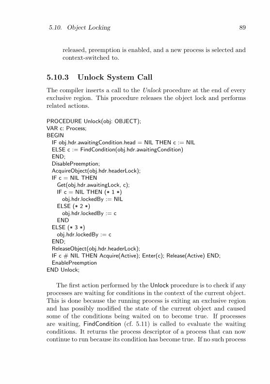
5.10. Object Locking 89
released, preemption is enabled, and a new process is selected andcontext-switched to.
5.10.3 Unlock System Call
The compiler inserts a call to the Unlock procedure at the end of everyexclusive region. This procedure releases the object lock and performsrelated actions.
PROCEDURE Unlock(obj: OBJECT);VAR c: Process;BEGIN
IF obj.hdr.awaitingCondition.head = NIL THEN c := NILELSE c := FindCondition(obj.hdr.awaitingCondition)END;DisablePreemption;AcquireObject(obj.hdr.headerLock);IF c = NIL THEN
Get(obj.hdr.awaitingLock, c);IF c = NIL THEN (* 1 *)
obj.hdr.lockedBy := NILELSE (* 2 *)
obj.hdr.lockedBy := cEND
ELSE (* 3 *)obj.hdr.lockedBy := c
END;ReleaseObject(obj.hdr.headerLock);IF c # NIL THEN Acquire(Active); Enter(c); Release(Active) END;EnablePreemption
END Unlock;
The first action performed by the Unlock procedure is to check if anyprocesses are waiting for conditions in the context of the current object.This is done because the running process is exiting an exclusive regionand has possibly modified the state of the current object and causedsome of the conditions being waited on to become true. If processesare waiting, FindCondition (cf. 5.11) is called to evaluate the waitingconditions. It returns the process descriptor of a process that can nowcontinue to run because its condition has become true. If no such process

90 Chapter 5. Multiprocessor Runtime Implementation
is found, it returns NIL. At this stage the object is still locked, so theconditions are conceptually evaluated inside the exclusive region.
After the conditions have been checked, the lock can be released. Asin the case of Lock, preemption is first disabled and the object headerspin lock is acquired.
There are now three cases to consider (numbered 1 to 3 in the com-ments above):
1. If no condition was found true and no process is waiting for thelock, the lock can simply be released by setting lockedBy to NIL.
2. If no condition was found true, but there are processes waiting forthe lock that is being released, the lock is granted to the processthat has been waiting the longest (the first in the lock queue). Asthe object header spin lock is held at this stage, the lock is trans-ferred atomically to the waiting process. There is no possibilityfor another process to execute the Lock procedure on another pro-cessor and ‘jump the queue’.
3. If a condition was found true, the lock is granted to the processthat had been waiting on it. As above, the lock is transferredatomically. There is no possibility for another process to enter theexclusive region in the meantime and falsify the condition again.
Next, the header spin lock is released. If a suspended process needsto be re-enabled because it was waiting on the lock or on a conditionthat is now true, the Active spin lock is acquired shortly and the processis entered into the ready queue. Then preemption is enabled again andthe procedure exits.
5.11 Object Condition Management
The synchronization of active objects is based on the await primitive(cf. 4.2.3), which allows the programmer to specify arbitrary booleansynchronization conditions. The compiler and runtime system cooper-ate to evaluate the conditions and suspend and re-enable processes asnecessary.

5.11. Object Condition Management 91
5.11.1 Await Statement
In Active Oberon, an AWAIT(b) statement, where b is an arbitraryboolean expression, is compiled into a helper procedure and an Awaitsystem call.
The helper procedure is equivalent to the following procedure, wherethe parameter specifies the frame pointer of the procedure containing theawait statement and all references to local variables and object fields inthe expression b are addressed relative to this parameter. A new name isgenerated for every helper procedure compiled and it can only be calledby the runtime system.
PROCEDURE $Condition(fp: ADDRESS): BOOLEAN;BEGIN
RETURN ”boolean expression from AWAIT statement”END $Condition;
At the location of the await statement, the equivalent of the fol-lowing code is compiled to perform the Await system call. The helperprocedure ($Condition) and the current frame pointer (FP) are passedto the runtime system so that it can later re-evaluate the condition [31].The self reference to the associated object instance is also passed asparameter.
IF NOT $Condition(FP) THENAwait($Condition, FP, SELF)
END
The generation of the inline IF statement by the compiler is an op-timization. Measurements made while the system was hosting its owndevelopment on a dual-processor machine have shown that this avoidson average 70-85% of Await system calls. As a further optimization,the compiler could inline the condition in the IF statement, saving aprocedure call at the cost of slightly more object code.
5.11.2 Await System Call
When the Await procedure is called, the IF statement generated by thecompiler has already found the condition false, so Await has to releasethe object lock, suspend the running process and set up the runtime
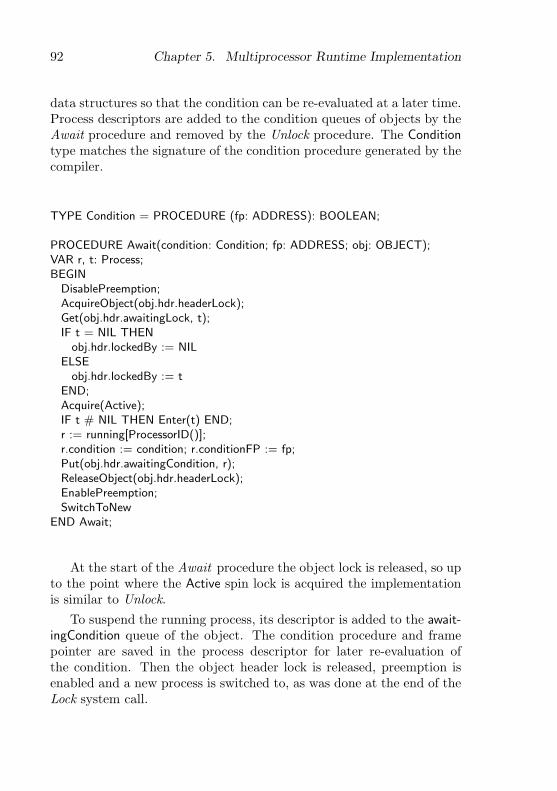
92 Chapter 5. Multiprocessor Runtime Implementation
data structures so that the condition can be re-evaluated at a later time.Process descriptors are added to the condition queues of objects by theAwait procedure and removed by the Unlock procedure. The Conditiontype matches the signature of the condition procedure generated by thecompiler.
TYPE Condition = PROCEDURE (fp: ADDRESS): BOOLEAN;
PROCEDURE Await(condition: Condition; fp: ADDRESS; obj: OBJECT);VAR r, t: Process;BEGIN
DisablePreemption;AcquireObject(obj.hdr.headerLock);Get(obj.hdr.awaitingLock, t);IF t = NIL THEN
obj.hdr.lockedBy := NILELSE
obj.hdr.lockedBy := tEND;Acquire(Active);IF t # NIL THEN Enter(t) END;r := running[ProcessorID()];r.condition := condition; r.conditionFP := fp;Put(obj.hdr.awaitingCondition, r);ReleaseObject(obj.hdr.headerLock);EnablePreemption;SwitchToNew
END Await;
At the start of the Await procedure the object lock is released, so upto the point where the Active spin lock is acquired the implementationis similar to Unlock.
To suspend the running process, its descriptor is added to the await-ingCondition queue of the object. The condition procedure and framepointer are saved in the process descriptor for later re-evaluation ofthe condition. Then the object header lock is released, preemption isenabled and a new process is switched to, as was done at the end of theLock system call.
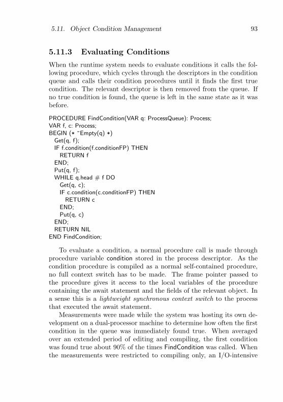
5.11. Object Condition Management 93
5.11.3 Evaluating Conditions
When the runtime system needs to evaluate conditions it calls the fol-lowing procedure, which cycles through the descriptors in the conditionqueue and calls their condition procedures until it finds the first truecondition. The relevant descriptor is then removed from the queue. Ifno true condition is found, the queue is left in the same state as it wasbefore.
PROCEDURE FindCondition(VAR q: ProcessQueue): Process;VAR f, c: Process;BEGIN (* ~Empty(q) *)
Get(q, f);IF f.condition(f.conditionFP) THEN
RETURN fEND;Put(q, f);WHILE q.head # f DO
Get(q, c);IF c.condition(c.conditionFP) THEN
RETURN cEND;Put(q, c)
END;RETURN NIL
END FindCondition;
To evaluate a condition, a normal procedure call is made throughprocedure variable condition stored in the process descriptor. As thecondition procedure is compiled as a normal self-contained procedure,no full context switch has to be made. The frame pointer passed tothe procedure gives it access to the local variables of the procedurecontaining the await statement and the fields of the relevant object. Ina sense this is a lightweight synchronous context switch to the processthat executed the await statement.
Measurements were made while the system was hosting its own de-velopment on a dual-processor machine to determine how often the firstcondition in the queue was immediately found true. When averagedover an extended period of editing and compiling, the first conditionwas found true about 90% of the times FindCondition was called. Whenthe measurements were restricted to compiling only, an I/O-intensive

94 Chapter 5. Multiprocessor Runtime Implementation
activity implying many process interactions, the average dropped tojust over 20%.
Interestingly, in all measured cases the average queue length whenFindCondition was called was 1.00, which implies that if there are con-ditions to check when an exclusive region is exited, on average only onecondition has to be checked.
To put the measurements in perspective, the condition queue wasfound empty in more than 98% of the cases where a process left anexclusive region. This means the FindCondition procedure was called inless than 2% of these cases, making the overhead of condition evaluationnegligible in comparison with the locking overhead.
5.12 Handling Multiple Processors
The Processors module is responsible for multiprocessor support, viz.,booting additional processors, interprocessor communication and localtimers.
Booting other processors. At startup, the hardware elects a bootprocessor that starts running the firmware boot loader [51]. After thekernel has been loaded, this processor executes the module initializationcode bottom-up until it gets to the Processors module, where the otherprocessors are recognized and started.
The boot processor scans the configuration information supplied byfirmware to find out at what address the APIC (cf. 5.1) is located andhow many processors are available, as well as what their physical IDnumbers are. Then it executes the following multiprocessor bootingalgorithm. For each processor to boot:
1. Set up a boot page in low memory with a simple 16-bit bootloader.
2. Use the APIC to send an init and startup interprocessor messageto the specified processor, to initialize it and cause it to startexecuting at the boot page.
3. Wait with a timeout for the new processor to set a flag in sharedmemory showing that it has booted successfully.
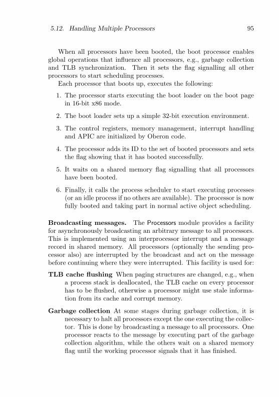
5.12. Handling Multiple Processors 95
When all processors have been booted, the boot processor enablesglobal operations that influence all processors, e.g., garbage collectionand TLB synchronization. Then it sets the flag signalling all otherprocessors to start scheduling processes.
Each processor that boots up, executes the following:
1. The processor starts executing the boot loader on the boot pagein 16-bit x86 mode.
2. The boot loader sets up a simple 32-bit execution environment.
3. The control registers, memory management, interrupt handlingand APIC are initialized by Oberon code.
4. The processor adds its ID to the set of booted processors and setsthe flag showing that it has booted successfully.
5. It waits on a shared memory flag signalling that all processorshave been booted.
6. Finally, it calls the process scheduler to start executing processes(or an idle process if no others are available). The processor is nowfully booted and taking part in normal active object scheduling.
Broadcasting messages. The Processors module provides a facilityfor asynchronously broadcasting an arbitrary message to all processors.This is implemented using an interprocessor interrupt and a messagerecord in shared memory. All processors (optionally the sending pro-cessor also) are interrupted by the broadcast and act on the messagebefore continuing where they were interrupted. This facility is used for:
TLB cache flushing When paging structures are changed, e.g., whena process stack is deallocated, the TLB cache on every processorhas to be flushed, otherwise a processor might use stale informa-tion from its cache and corrupt memory.
Garbage collection At some stages during garbage collection, it isnecessary to halt all processors except the one executing the collec-tor. This is done by broadcasting a message to all processors. Oneprocessor reacts to the message by executing part of the garbagecollection algorithm, while the others wait on a shared memoryflag until the working processor signals that it has finished.
96 Chapter 5. Multiprocessor Runtime Implementation
Memory cache control Each processor has its own caches and cachecontrol registers. When a device driver needs to change cachingbehaviour, e.g., to enable write buffering on a frame buffer, this isdone on all processors by broadcasting the relevant message.
The Broadcast procedure defined below is exported for use in devicedrivers. Its handler parameter specifies a procedure that will be calledindividually by all processors to process the message. The Message typecan be extended to send arbitrary information with the broadcast. Theconstants are used as flags for the procedure. The Self flag specifieswhether the calling processor should itself receive the message. Thetwo barrier flags specify whether the processors should synchronize atthe start and end of the message handling procedure, respectively.
CONSTSelf = 0; FrontBarrier = 1; BackBarrier = 2; (* flags for Broadcast. *)
TYPEMessage = POINTER TO RECORD END;Handler = PROCEDURE (msg: Message; ...);
PROCEDURE Broadcast(h: Handler; msg: Message; flags: SET);
Local timers. The APIC on each processor has a timer which can beprogrammed to interrupt the processor periodically. On multiprocessormachines, this timer is programmed to perform timeslicing (cf. 5.9.4).The timer runs at the bus clock rate, therefore the bus clock speed has tobe measured first, using an external timer device with a known frequencyas reference. If the processor does not have an APIC (e.g., an oldersingleprocessor PC), the external timer device is used for timeslicinginstead.
5.13 Kernel Services
Kernel module. The Kernel module is the main module of the Aoskernel. It provides facilities that require the support of all the otherkernel modules. Unlike lower-level kernel modules, it does not exportany implementation details and its interface can therefore be consideredstable and portable, even when the kernel implementation changes. The
5.13. Kernel Services 97
interface consists of three sections: fine-grained timers, primitive atomicoperations and finalized collections.
Fine-grained timers. The fine-grained timer facility is provided foraccurate measurement of time periods. It is based on a counter that isperiodically incremented at a fixed frequency. The GetTimer procedurebelow returns the current value of the counter. The timer frequencyis a characteristic of the underlying implementation and is thereforeexported as a variable, although its value remains constant.
VAR second: LONGINT; (* timer counts per second *)
PROCEDURE GetTimer(): LONGINT;
For more convenient access to the timer, some auxiliary proceduresare provided to manipulate an abstract timer. The SetTimer proceduresets a timer to expire in the specified time, Expired tests whether a timerhas expired, Elapsed returns the elapsed time and Left returns the timeleft before expiry.
TYPETimer = RECORD END; (* opaque *)
PROCEDURE SetTimer (VAR t: Timer; ms: LONGINT);PROCEDURE Expired (VAR t: Timer): BOOLEAN;PROCEDURE Elapsed (VAR t: Timer): LONGINT;PROCEDURE Left (VAR t: Timer): LONGINT;
Primitive atomic operations. In Active Oberon, any operation canbe made atomic by wrapping it in an active object with exclusive meth-ods, but for efficiency the kernel also exports some primitive atomicoperations on simple data types:
PROCEDURE Inc(VAR x: LONGINT); (* x’ := x + 1 *)PROCEDURE Dec(VAR x: LONGINT); (* x’ := x - 1 *)PROCEDURE Add(VAR x: LONGINT; y: LONGINT); (* x’ := x + y *)PROCEDURE TestSet(VAR x: BOOLEAN): BOOLEAN; (* x’ := true; return x *)

98 Chapter 5. Multiprocessor Runtime Implementation
Finalized collections. The finalized collections mentioned in sec-tion 5.6 are provided with the interface shown below. The Add methodadds an arbitrary object reference to a collection. If the fin procedureparameter is non-NIL, the specified procedure will be called before theobject is deallocated. The Remove method removes an object from thecollection. The Enumerate method enumerates the collection contentsby calling the specified procedure once for each object currently in thecollection (as long as the cont parameter is not set to FALSE).
Objects are automatically removed from the collection when they areno longer reachable (just before the optional finalization procedure iscalled). The finalization procedures are called from a separate process,so that they can acquire arbitrary locks.
TYPEFinalizer = PROCEDURE (obj: PTR);Enumerator = PROCEDURE (obj: PTR; VAR cont: BOOLEAN);FinalizedCollection = OBJECT
PROCEDURE Add(obj: PTR; fin: Finalizer);PROCEDURE Remove(obj: PTR);PROCEDURE Enumerate(enum: Enumerator);
END;
Chapter 6
System Services
This chapter describes the system services layer of the active objectsystem (the middle layer in figure 3.1). The layer contains shared systemservices, e.g., the communication and file subsystems and their devicedrivers. Its modules can be classified into three kinds (cf. 3.6):
Service modules These modules provide standard interfaces for sys-tem services. They typically declare abstract objects that are im-plemented in plugin modules and used in client modules. A clientlocates a service by importing the service module and queryingthe registry exported there.
Plugin modules The plugin modules implement the interfaces definedby service modules, normally by extending the abstract objectsdeclared there. Specific instances of the service objects are enteredin the registry exported by the service module.
Helper modules These modules provide auxiliary functions, e.g., con-figuration and device driver support.
6.1 Files
Files are used for external storage. A file is a sequence of bytes normallyaccessed sequentially, but can also be accessed randomly. It can benamed or anonymous. Files are normally used for permanent storage,but can also be used for temporary external storage (usually anonymousfiles).
99

100 Chapter 6. System Services
FATFS
ISOFS
NatFS
UsbStorage
Adaptec7
SCSI
ATA
Disks
FS
DiskFS
DiskVolumes
RAMVolumes
Caches
Figure 6.1: File subsystem structure.
6.1.1 File Systems
The Ceres Oberon system provided a single file system module with twocompatible implementations. The first stored files permanently on disk,and the second stored files semi-permanently (until the next power-off)in RAM. In Native Oberon, there was a need to allow many kinds of filesystem for interoperability with other operating systems installed on thesame machine, to access several kinds of removable media with their ownfile system formats, and to access file systems located on remote servers.The installable file system framework developed for Native Oberon wasadapted and refined for Aos. An overview of the modules is shown infigure 6.1.
FS module. The FS (short for file system) module defines an abstractfile system object that can be extended to define different kinds of filesystems. An instance of such an object is responsible for managing each

6.1. Files 101
file system. As in the Disks module, concrete file system objects can beimplemented in other modules that extend the types of the FS module.
The module defines a system-wide file name space. A file name con-sists of two parts: a file system specifier and a local file name, separatedby a colon. The specifier is a prefix that uniquely identifies a specific filesystem currently accessible on the system. The local file name identifiesa file uniquely in the specific file system (which might use a hierarchicalnaming scheme).
The data stored in a file system exists statically on disk or some otherstorage device. To make the data accessible to programs, a file systemobject has to be instantiated and registered in the file name space of theFS module. This is done automatically by the system (e.g., for the bootfile system), or manually by a user with a file system command tool orconfiguration file. The process is called mounting as the file system isconnected into the name space at this point. A unique prefix can befreely assigned to the file system at this time.
The FS module also defines an abstract volume object, which canbe used as an intermediate object between a file system implementationand the underlying block device (a volume can be seen as a kind ofvirtual disk device). In this way, different file systems can be mappedto different partitions on the same disk, or a file system can be attachedto a virtual disk in RAM.
Aos disk file system. The DiskFS module implements a concretefile system based on an abstract volume, of which two concrete imple-mentations exist: module DiskVolumes implements a volume based ona disk device and RAMVolumes implements a virtual RAM volume. Bycombining a file system object with either of the two kinds of volumeobject, a file system on a real disk or a virtual disk can be accessed.
The implementation of the file system is based on that of NativeOberon, but the maximum file and volume size have been increased byincreasing the volume block size and by using a double indirection in thefile system structures. The disk volume object uses the Caches moduleto providing write-through and write-back caching, which significantlyimproves file system performance.
Caches module. The Caches module defines a generic cache objectfor block devices. A cache manages a fixed number of buffers that can

102 Chapter 6. System Services
contain data read from and written to different disks with the sameblock size. A write-through or write-back cache policy can be used.Clients of a cache call the Acquire and Release methods to obtain andreturn buffers, respectively. Clients should modify only the data field ofa buffer — the rest of the buffer is under control of the cache object.The Synchronize method is used to write all modified buffers to disk.
TYPEBuffer = POINTER TO RECORD
data: DataBlock; dev: Disks.Disk; block: LONGINTEND;Cache = OBJECT
VAR blockSize: LONGINT;PROCEDURE Acquire(dev: Disks.Disk; block: LONGINT;
VAR buf: Buffer; VAR valid: BOOLEAN);PROCEDURE Release(buf: Buffer; modified, written: BOOLEAN);PROCEDURE Synchronize;PROCEDURE &Init(blockSize, cacheSize: LONGINT);
END Cache;
The Acquire method acquires a buffer for the disk block specified bythe dev and block parameters. If the buffer is already in the cache, itis locked and returned in the buf parameter with the valid parametertrue, to indicate to the client that no disk read needs to be made (it isassumed that all clients access the disk through the cache). If the bufferis not in the cache, the cache returns the least-recently used unlockednon-dirty buffer for reuse. If all buffers are currently in use, it waits for abuffer to become available (it is assumed that all buffers are eventuallyreleased). The returned buffer is locked and returned with the validparameter false (as it does not contain the desired disk block yet). Thecaller is responsible for reading the required block into the buffer.
The Release method releases a buffer to the cache. The modifiedparameter specifies whether the buffer has been modified by the callersince it was acquired and the written parameter specifies whether thecaller has written the buffer to disk.
The Synchronize method writes all currently dirty buffers back todisk. This method can be called at any time to synchronize the buffercontents with the disk. The cache itself calls the method when non-dirtybuffers become scarce.

6.1. Files 103
The implementation of the cache object contains examples of non-trivial await statements. In one case the Acquire method waits for thestate of a buffer object to change. Although the condition being waitedon is apparently not local to the cache object (it depends on the stateof a buffer, not the cache or method), it can only be established by oneof the cache object methods modifying the internal state of the buffer.The state of the buffers can be seen as an extension of the cache objectstate, as it is only modified under control of the cache object in anexclusive region of the cache object.
In another case, the Acquire method has to wait for a non-dirty bufferto appear in the least-recently-used list. As it would not be efficient totraverse the whole list every time the condition is checked, the cachemaintains a counter of the number of dirty buffers in the list. Thecounter invariant is established every time the list is modified.
The cache object manages disk blocks declared by a block deviceobject, described below.
6.1.2 Disk Drivers
Disks module. The Disks module primarily serves to define the Diskobject, which is an abstraction for general block devices. This objecthas some abstract methods that are extended and overwritten by devicedriver modules for hard disks, diskettes and other random-access blockdevices to implement concrete device driver objects. One such objectis instantiated for each block device used in the system. A modulethat needs to access such a block device calls the methods of the spe-cific instance directly. In this way the Disks module defines an abstractinterface for block devices.
When designing the abstract interface, our main concern was to de-fine a simple abstraction that is general, extensible, and does not impedeperformance. The essence of the interface is shown in the definition ofthe Disk object below. A disk is modeled as an array of equally-sizeddata blocks numbered sequentially. The two most important operationson it are modelled as methods. The Transfer method transfers (readsor writes) a contiguous collection of disk blocks between the disk andmemory. The GetSize method returns the size (number of blocks) of themedia currently in the drive. The block size is assumed to be fixed for adevice, even if the media can be changed. It is exported as the blockSize

104 Chapter 6. System Services
field of the object.
CONST Read = 0; Write = 1; (* values for op parameter *)TYPE
Disk = OBJECT (Plugins.Plugin)VAR blockSize: LONGINT; ...PROCEDURE Transfer (op, block, num, ofs: LONGINT;
VAR data: ARRAY OF CHAR; VAR res: LONGINT);PROCEDURE GetSize (VAR size, res: LONGINT);
END Disk;
The Transfer method is synchronous (blocking), which means that itdoes not return until the transfer is complete, or an error has occurred(indicated by a non-zero res parameter). If parallel requests to a diskneed to be made for performance reasons, this can be done by calling themethod from different active objects. In this way all asynchronicity inthe device interface is hidden in the device driver implementation, andnot exported to higher levels with an asynchronous interface utilizing,e.g., callbacks or signals.
The Disk object is a plugin (cf. 3.6) and the Disks module providesa registry for disk objects. A module that needs to access a disk devicequeries the registry to find the required device by name. A disk devicedriver module instantiates a disk object for each device it manages andregisters each instance here with a unique name.
VAR registry: Plugins.Registry;
The minimal interface presented above is sufficient for most currentuses of block devices in the system. However, it is not possible to foreseeall possible cases and define them in a standard interface. Therefore ageneric message handler method is provided for message-based exten-sion of the interface. The Handle method accepts a generic Messagerecord, which can be extended in other modules when necessary. Han-dling of a message is optional; if it can not handled a non-zero result isreturned. A few pre-defined messages (EjectMsg, GetGeometryMsg, etc.)are provided for common operations that are nonetheless not availableon all devices.
TYPEMessage = RECORD END;

6.2. Communication 105
Disk = OBJECT (Plugins.Plugin) ...PROCEDURE Handle (VAR msg: Message; VAR res: LONGINT); ...
END Disk;EjectMsg = RECORD (Message) END;GetGeometryMsg = RECORD (Message)
cyls, hds, spt: LONGINTEND; ...
In addition to the functions described here, the Disks module also de-fines some auxiliary procedures for reading disk partition tables, whichare used to partition a disk into different sections for different operatingsystems or file systems.
Disk device drivers. A disk device driver module extends the ab-stract disk object defined by the Disks module and implements at leastthe Transfer and GetSize methods defined there. When the module isloaded, it creates an instance of such an object for every compatibledisk in the system, and registers the object with the plugin registry inthe Disks module.
An example of such a driver module is the ATADisks module. It im-plements a driver for ATA (i.e., IDE) standard disks [8] connected to anATA bus controller. The motherboard chipsets of most IA-32 machineshave such integrated controllers, e.g., the Intel 82371SB [52]. Most ofthese controllers are backward-compatible with older models, but for thebest performance, a driver has to be customized for a specific chipset.A possible approach is to make the concrete drivers extensible [75].
It is relatively simple to port Native Oberon disk drivers to Aos,as they use a similar interface to an abstract disk object. The mainconcerns when porting are protecting the objects using exclusive regions,adapting the interrupt handling (cf. 4.3.3) and adapting direct memoryaccess to the Aos memory model (cf. 4.3.1). In this way Native Oberondrivers for Adaptec SCSI bus controllers [4] and USB storage devices [87,123] have been ported by users of Aos.
6.2 Communication
The communication subsystem is an important component of the sys-tem, as it allows the system to access and provide services in the in-ternet. It consists of three parts: the internet protocols, TCP agent
106 Chapter 6. System Services
services and link layer device drivers. An overview of the modules isshown in figure 6.2.
6.2.1 Internet Protocols
The basic internet protocols [54] were implemented for Aos, to allow itto support internet applications. The protocols were implemented in amodular fashion, with one module for every major protocol in the suite.
IP module. The IP module implements the closely-related internetprotocol (IP) [92], internet control message protocol (ICMP) [91] andaddress resolution protocol (ARP) [88], which provide basic internet ad-dressing and connectivity. The implementation is based on the abstractlink device defined in the Net module, which can be instantiated withan ethernet driver for LAN connectivity or a point-to-point protocol(PPP) [113] implementation for point-to-point connectivity.
When IP datagrams are received, they are passed to higher-levelmodules for handling using the Input upcall procedure defined below.The Output procedure sends the specified IP datagram out on the spec-ified link device.
TYPEInput = PROCEDURE (dev: Net.LinkDevice; VAR iphdr: Net.RecvHdr;
hlen, dlen: LONGINT);PROCEDURE Output(dev: Net.LinkDevice; VAR hdr: Net.RecvHdr;
VAR data: ARRAY OF CHAR; hlen, dofs, dlen: LONGINT);
The ARP protocol is responsible for mapping IP addresses to linklayer addresses on a LAN. Its main data structure is a table containingthe current mappings. This is implemented as an object with exclusivemethods for entering information in the table and a non-exclusive lookupmethod allowing concurrent lookup operations. The table also stores IPpackets to be sent to addresses that are still being resolved. As soon asthe relevant ARP reply is received, the packets are sent.
UDP module. The UDP module implements the user datagram pro-tocol (UDP) [90], which provides simple connectionless datagram facili-ties to higher-level network protocols and applications. The implemen-tation is based on the facilities provided by the IP module.
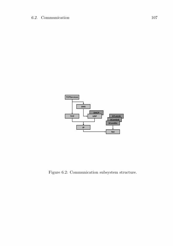
6.2. Communication 107
DHCP
UDP
DNS
Net
RTL8139
3Com5x9
3Com90x
TCP
IP
TCPServices
Figure 6.2: Communication subsystem structure.
108 Chapter 6. System Services
The Socket object defined below functions as a UDP communicationendpoint. A local UDP port number is associated with the object inthe Open method. Datagrams that arrive for this port are bufferedinternally in the object until they are read with the Receive method. Ifcalled when no data is available, this method waits until data becomesavailable, or until the specified timeout expires. It returns the dataof the datagram and the foreign IP address and port number. TheSend method is used to send a datagram to the specified foreign IPaddress and port number. The Close method is used to stop bufferingof incoming datagrams and to make the local port number available forre-use.
TYPESocket = OBJECT
PROCEDURE &Open(lport: LONGINT; VAR res: LONGINT);PROCEDURE Send(fip: IP.Adr; fport: LONGINT;
VAR data: ARRAY OF CHAR; ofs, len: LONGINT; VAR res: LONGINT);PROCEDURE Receive(VAR data: ARRAY OF CHAR; ofs, size, ms: LONGINT;
VAR fip: IP.Adr; VAR fport, len, res: LONGINT);PROCEDURE Close;
END Socket;
DNS module. The DNS module implements a domain name service(DNS) [67, 68] client, which is based on UDP and mainly used to trans-late domain names (e.g., www.oberon.ethz.ch) into IP addresses (e.g.,129.132.178.197).
The module has a very simple interface. The HostByName proceduretranslates an internet host’s domain name into an IP address. The Host-ByNumber procedure performs the reverse translation.
PROCEDURE HostByName(hostname: ARRAY OF CHAR;VAR adr: IP.Adr; VAR res: LONGINT);
PROCEDURE HostByNumber(adr: IP.Adr;VAR hostname: ARRAY OF CHAR; VAR res: LONGINT);
DHCP module. The DHCP module implements a dynamic host con-figuration protocol (DHCP) [32] client, which is used to initialize theTCP/IP subsystem without requiring manual intervention. The proto-col is based on UDP and works by contacting a DHCP server on the

6.2. Communication 109
LAN during initialization. The server returns internet protocol parame-ters like the IP address, netmask, DNS server address, etc. IP addressesare assigned based on a static configuration for the host at the server,or are dynamically assigned by the server from a fixed pool of addresses.Automatic network configuration makes it possible to boot Aos from aCD or diskette and immediately use it to access the internet, withouthaving to install it on the hard disk of a computer.
TCP module. The TCP module implements the transmission controlprotocol (TCP) [93], which is a connection-based protocol providing abidirectional reliable byte stream connection between two internet hosts.The TCP protocol is significantly more complex than the other protocolspresented so far. The Aos implementation is based on the ubiquitousBSD implementation of TCP [65, 135], but has been adapted to be moreobject-oriented and concurrent.
The Connection object defined below functions as a TCP communi-cation endpoint.
TYPEConnection = OBJECT
PROCEDURE Open(lport: LONGINT; fip: IP.Adr; fport: LONGINT;VAR res: LONGINT);
PROCEDURE Send(VAR data: ARRAY OF CHAR; ofs, len: LONGINT;VAR res: LONGINT);
PROCEDURE Receive(VAR data: ARRAY OF CHAR; ofs, size, min: LONGINT;VAR len, res: LONGINT);
PROCEDURE AwaitState(good, bad: SET; ms: LONGINT; VAR res: LONGINT);PROCEDURE Close;PROCEDURE Accept (VAR client: Connection; VAR res: LONGINT); ...
END Connection;
The Open method is used to open an active or passive connection,where an active connection is used by a client to contact a server, anda passive connection is used by a server to wait for client connections.The fip (foreign IP address) parameter is used to distinguish betweenthe two cases, with a zero address specifying a passive connection. Thelport parameter specifies the local TCP port number. If it is zero, a freeport is assigned automatically. A connection is closed with the Closemethod, which performs a TCP half-close operation.

110 Chapter 6. System Services
Opening and closing are asynchronous operations. The methods ini-tiate the operation and return immediately, while the operation is per-formed in the background by an active object. The AwaitState methodis provided to synchronize with the TCP connection state changes, e.g.,to wait until a connection is established.
For data transfer, the Send and Receive methods are provided.When a client connection request arrives on a passive connection, it
is queued internally until it is accepted by the server calling the Acceptmethod, which returns a new connection object for communication be-tween the client and server. In the mean time, the passive connectioncan accept new client connection requests.
The connection object can be shared between multiple processes.This is typically used in servers to allow different agent processes toaccept client connections on a shared passive connection. When a clientrequest arrives, one of the agents will accept it and start communicatingwith the client. Meanwhile, the other agents continue waiting for clientrequests (cf. 6.2.2).
TCP implementation structure. Figure 6.3 shows the objects thattake part in the Aos TCP implementation. The TCP module defines fourtypes of object: connection, connection pool, timer and sequence num-ber source (shaded in the figure). Two other types of object from othermodules take part (unshaded in the figure): the link device (cf. 6.2.3)and system timer. One connection object is instantiated for every con-nection, a link device object is instantiated for every configured linkdevice, and one instance of each of the other objects is shared betweenall the connections. The connection pool object stores all connectionsthat currently exist, the sequence number source object generates ini-tial send sequence numbers for connections and the timer object handlesTCP timers.
The connection object encapsulates the state of a TCP connectionand forms the core of the implementation. It reacts on messages fromdifferent sources, implemented as exclusive methods. Most of the meth-ods are exported from the module and form the programming interfacedescribed above. The other methods are used internally for communi-cation with the other objects taking part in the implementation.
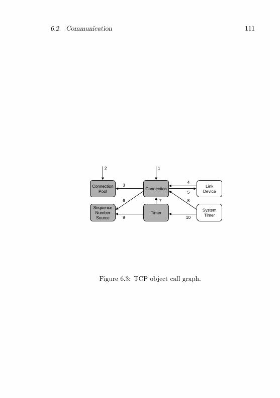
6.2. Communication 111
1
Connection
SequenceNumberSource
Timer
ConnectionPool
SystemTimer
LinkDevice
3
2
4
5
6 8
9 10
7
Figure 6.3: TCP object call graph.
112 Chapter 6. System Services
Deadlock avoidance. In an environment where exclusive methods ofone object calls exclusive methods of other objects, there is the dangerof hold-and-wait deadlock. We now prove informally that this is not thecase in the TCP implementation.
The arrows in figure 6.3 indicate which objects call methods of whichother objects from their own methods. All exclusive method calls areshown, and no object calls its own exclusive methods. The method callsare:
1. The exported methods of the connection object, Open, Send, Re-ceive, AwaitState, Close and Accept, can be called from outside themodule, but only from higher-level modules, which are not calledby the TCP module.
2. Likewise, the connection pool object exports Enumerate.
3. A connection object calls the SetLocalAddr, SetForeignAddr, Set-Addrs and Remote methods of the connection pool object.
4. A link device object calls the Input method of a connection objectwhen a packet arrives for the connection.
5. Conversely, a connection object calls the Send method of a linkdevice object when it sends a packet.
6. A connection object calls the Get method of the sequence numbersource object when it is opened.
7. The timer object calls the DelayedAck and SlowTimer methods ofa connection when the relevant timers expire.
8. The system timer object calls the HandleTimeout method of aconnection when a timeout occurs.
9. The timer object calls the Update method of the sequence numbersource object periodically.
10. The system timer object calls the HandleTimeout method of thetimer periodically.
The exclusive method call graph is acyclic by design (with one ex-ception), and this can be verified informally by inspection of the source

6.2. Communication 113
code. The exception is that connection and link device objects can calleach other (cases 4 and 5 above). Therefore, this is the only case wherea deadlock can possibly occur, as no cyclic waits are possible otherwise.
As an example of how deadlock can occur, consider the case wherean acknowledgement packet arrives for a specific connection. The linkdevice object calls the Input method of the connection (from an exclusivemethod) and the connection processes the packet, adjusts the send win-dow and if buffered data is available, calls the Send method of the samelink device to send out a data packet. If this method is also exclusive,it will result in deadlock.
The problem is solved in different ways in different link device drivers(cf. 6.2.3). For example, the 3C90X driver splits up the link deviceobject into two objects internally and the 3C5X9 driver uses explicitlocking and queues packets if the object is already locked.
Await statement examples. The connection object implementationcontains some examples of non-trivial await statements. For example,the following condition in Send waits until the connection is establishedand the send window has space for a data segment, or until the connec-tion is terminated (whichever comes first):
AWAIT(((state IN {Established, CloseWait}) & (sndspace >= len0)) OR~(state IN {SynSent..CloseWait}))
With the following statement the Receive method waits until data isavailable, or the connection is terminated:
AWAIT((rcvhead.len # 0) OR ~(state IN {SynSent..Established, FinWait1, FinWait2}))
The following statement in AwaitState is used to wait for either agood or bad TCP state to occur, or a timeout. The former conditionis typically signalled by packet processing and the latter by the timerobject:
AWAIT((state IN (good+bad)) OR (Timeout IN flags))
The Accept method consists mainly of the following statement, whichwaits until the passive connection is closed, or a new client connectionrequest has been queued by packet processing.
AWAIT((state # Listen) OR (acceptNext # NIL))
114 Chapter 6. System Services
6.2.2 TCP Agent Services
The TCPServices module (definition below) facilitates the implementa-tion of active object-based TCP server applications. The Service objectdefined in the module automatically handles connection acceptance andcreates an active object (agent) to service each incoming client connec-tion. The active object receives a handle on the connection with whichit can receive client requests and send server responses.
TYPENewAgent = PROCEDURE (c: TCP.Connection; s: Service): Agent;Service = OBJECT
PROCEDURE &Start(port: LONGINT; new: NewAgent; VAR res: LONGINT);END Service;Agent = OBJECT
VAR client: TCP.Connection;PROCEDURE &Start(c: TCP.Connection; s: Service);PROCEDURE Terminate;
END Agent;PROCEDURE OpenService(VAR service: Service; port: LONGINT; new: NewAgent);PROCEDURE CloseService(VAR service: Service);
The Agent object is an abstract agent object, which is extendedwith an active body by a module implementing an actual agent. Theexported client field is a handle on the TCP connection to the client.When the agent has finished processing client requests, it calls the Ter-minate method to signal to its service object that it is terminating.
A new service is instantiated with the OpenService procedure, wherethe port parameter specifies the TCP port on which the server shouldlisten for client connections. The new procedure parameter specifiesa generator procedure for agents that will provide the actual service.Every time a client connection arrives, the service object calls this pro-cedure to generate a new agent to serve the client.
Example service: Echo. The example agent below implements theTCP echo service [89]. It receives all input from the client connectioninto a buffer and sends it back unchanged to the client. This contin-ues until the client closes the connection (res 6= 0) and then the agentterminates.

6.2. Communication 115
TYPEEchoAgent = OBJECT (TCPServices.Agent)
VAR len, res: LONGINT; buf: ARRAY 4096 OF CHAR;BEGIN {ACTIVE}
LOOPclient.Receive(buf, 0, LEN(buf), 1, len, res);IF res # 0 THEN EXIT END;client.Send(buf, 0, len, res);IF res # 0 THEN EXIT END
END;Terminate
END EchoAgent;
The following procedure is used as a generator for echo agents. Itsimply allocates the relevant agent object, passing the supplied TCPconnection as parameter to its initializer, and then returns the newobject.
PROCEDURE NewEchoAgent(c: TCP.Connection;s: TCPServices.Service): TCPServices.Agent;
VAR a: EchoAgent;BEGIN
NEW(a, c, s); RETURN aEND NewEchoAgent;
To complete the example, the initialization of the service is shownbelow. The second parameter of the OpenService call specifies the TCPport number (the standard echo port is 7), and the third parameterpasses the echo agent generator to the echo service object.
VAR echo: TCPServices.Service;BEGIN
TCPServices.OpenService(echo, 7, NewEchoAgent)END
Example service: Web server. The following example outlines asimple HTTP 1.0 [11] web server agent. It shows how an agent canassign an input and output buffer on the client connection, so that it canefficiently parse client data character-by-character (in the ParseRequestprocedure) and buffer the response sent to the client.
116 Chapter 6. System Services
TYPEHTTPAgent = OBJECT (TCPServices.Agent)
VAR ...BEGIN {ACTIVE}
IO.OpenReader(in, client.Receive);IO.OpenWriter(out, client.Send);ParseRequest(in, uri, host, method, res);IF res = Ok THEN
LocateResource(uri, host, method, type, f, res);IF res = Ok THEN
WriteHeader(out, type);IF f # NIL THEN WriteFile(out, f) END
ENDEND;IF res # Ok THEN WriteStatus(out, res) END;IO.Update(out);Terminate
END HTTPAgent;
The initialization of the service object is similar to the echo example,except that the HTTPAgent is generated instead of the EchoAgent, andthe standard HTTP port 80 is used in the OpenService call.
6.2.3 Network Drivers
Net module. The Net module defines an abstract network link layerdevice object. As in the Disks module, other modules extend the objectto implement device driver objects. A link layer device, e.g., an ethernetnetwork controller, can send and receive packets on the network. Itforms the lowest-level software part of the networking system.
For sending packets, the link device provides the Send method, whichaccepts a destination address, packet type and payload. The payload issplit into a protocol header and data part. The device driver combinesthe link layer header, protocol header and data into one packet, whichreduces the number of copy operations that have to be performed onthe data. In order to keep the interface relatively simple, a more generaldata gathering facility is not provided. Typically, the send operationenqueues the data and returns immediately.
TYPE
6.2. Communication 117
LinkDevice = OBJECT (Plugins.Plugin)VAR local, broadcast: LinkAdr; mtu: LONGINT; ...PROCEDURE Send(dst: LinkAdr; VAR hdr, data: ARRAY OF CHAR;
type, hlen, dofs, dlen: LONGINT); ...END LinkDevice;
The local field of the link device contains the local link layer addressand the broadcast field contains the link layer broadcast address. Themtu field defines the largest packet that can be delivered by the linklayer.
Receiving of packets is implemented with an upcall mechanism. Areceiver procedure for a specific packet type can be installed with thedevice object. When a packet of this type arrives, the procedure iscalled by the device. The protocol header of the packet is passed tothe upcall, and the rest of the data can be obtained with the RecvDatamethod.
TYPEReceiver = PROCEDURE (dev: LinkDevice; VAR hdr: RecvHdr;
len, type: LONGINT; src: LinkAdr);LinkDevice = OBJECT (Plugins.Plugin) ...
PROCEDURE InstallRecv(type, hlen: LONGINT; h: Receiver);PROCEDURE RemoveRecv(type: LONGINT; h: Receiver);PROCEDURE GetRecv(type: LONGINT; VAR h: Receiver; VAR hlen: LONGINT);PROCEDURE RecvData(VAR data: ARRAY OF CHAR; ofs, size: LONGINT); ...
END LinkDevice;
As in the Disks module, the Net module provides a registry for linkdevice objects.
VAR registry: Plugins.Registry;
Link layer device drivers. The first link layer device driver imple-mented for Aos was a driver for the 3Com 3C5X9 ethernet controller [1],which is relatively simple and well-documented. When the driver mod-ule is loaded, the controller is detected, initialized and a device driverobject is allocated and registered with the Net module. A reference tothe driver object is obtained from here by the higher-level protocol mod-ules. When a protocol wants to send a packet, it calls the Send method,which waits until buffer space is available on the controller, then trans-fers the packet directly to the controller’s buffer, and returns while the
118 Chapter 6. System Services
controller sends the packet out on the wire. For receiving packets, theprotocol registers a receiver procedure with the driver object. When apacket arrives, the controller interrupts the driver object, which copiesthe packet to memory and calls the receiver to handle the packet.
At a later stage, a driver for the 3Com 3C90X ethernet controller [2]for Native Oberon [115] was ported to Aos. This controller uses directmemory access (DMA) to transfer packets from and to memory. Thisdriver works similarly to the one described above, but also managesspecial buffers for DMA. The data from the network is deposited straightinto these buffers by the controller and can then be copied directly tothe application by the protocol.
Most recently, a driver for the Realtek RTL 8139 ethernet con-troller [97], which also uses DMA, has been implemented by a userof Aos.
6.3 User Interface
A user interface for the Aos system is being developed in a separateproject. Although the window manager developed in that project al-ready allows different applications to share the display and input de-vices, it is not rich enough yet to allow day-to-day work to be done ex-clusively in that environment. In the meantime Oberon for Aos (cf. 7.1)is used as the primary user interface for development, but it has thedisadvantage that it does not allow arbitrary concurrency, thereby re-stricting the user interaction capabilities of active objects. This sectiondescribes the underlying user interface device drivers. An overview ofthe modules is shown in figure 6.4.
6.3.1 Display Drivers
Displays module. The Displays module defines the Display abstractraster device object that can be extended by display driver modules. Itsinterface is purposely kept small but general enough to be usable withmost common raster display devices. The idea is to provide a uniformdevice interface for a higher-level graphics library, e.g., the one definedin [77]. The abstract raster device consists of a two-dimensional arrayof pixels with an integer device coordinate system.
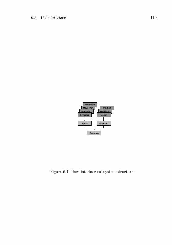
6.3. User Interface 119
MouseUsb
MouseV24
DisplaysInputs
MousePS2
Keyboard
Mach64
Permedia2
Linear
Messages
Figure 6.4: User interface subsystem structure.

120 Chapter 6. System Services
Basic interface. The basic interface of the Display object is shownbelow. The Dot method draws a dot in the specified colour at position(x, y) and Fill fills the rectangular area specified by (x, y, w, h) withthe specified colour. The Mask method fills the specified rectangulararea with a tiled monochrome pattern in the specified foreground andbackground colour. The width and height fields export the size of theraster.
CONSTred = 00FF0000H; green = 0000FF00H; blue = 000000FFH;trans = 80000000H; invert = 40000000H;
TYPEDisplay = OBJECT (Plugins.Plugin) ...
VAR width, height: LONGINT; ...PROCEDURE Dot(col, x, y: LONGINT);PROCEDURE Fill(col, x, y, w, h: LONGINT);PROCEDURE Mask(VAR buf: ARRAY OF CHAR; bitofs, stride,
fg, bg, x, y, w, h: LONGINT); ...END Display;
All these methods use an RGB true-colour model with colours en-coded as 32-bit integers, usually written as hexadecimal constants. Thelow 24 bits specify the RGB components of the colour and the high 8 bitsare used as flags, of which two are currently defined. The trans flag in-dicates a fully transparent colour and is used with the Mask method to‘paint’ a pattern on the existing raster contents. The invert flag indicatesthat the colour should be combined with the existing raster contents in areversible way — if the same colour is drawn twice, the original contentsis restored — typically implemented with an XOR operation.
As in the Disks module, the Displays module provides a registry fordisplay driver objects:
VAR registry: Plugins.Registry;
Low-level interface. For efficient block transfers to and from theraster frame buffer, the low-level interface below is provided. The Copymethod copies the rectangular area specified by (sx, sy, w, h) to position(dx, dy). The Transfer method transfers a buffer containing colour valuesin the transfer format to, or from, the rectangular area specified by(x, y, w, h). The op parameter indicates the direction.

6.3. User Interface 121
CONSTget = 0; set = 1;index8 = 1; color565 = 2; color888 = 3; color8888 = 4;
TYPEDisplay = OBJECT (Plugins.Plugin)
VAR format: LONGINT; ...PROCEDURE Copy(sx, sy, w, h, dx, dy: LONGINT);PROCEDURE Transfer(VAR buf: ARRAY OF CHAR; ofs, stride,
x, y, w, h, op: LONGINT);PROCEDURE ColorToIndex(col: LONGINT): LONGINT;PROCEDURE IndexToColor(index: LONGINT): LONGINT; ...
END Display;
Four transfer formats are defined, allowing a driver to expose a for-mat that can be converted efficiently to its native frame buffer format.If a graphics library uses this low-level interface, it is responsible formapping the driver’s transfer format to its own internal format. Theindex8 format uses 8 bits to represent a pixel and the value is an in-dex into a fixed colour table that can be queried with the ColorToIndexand IndexToColor methods. It is mostly intended for low-end deviceswith small memories. The color565 format uses 16 bits per pixel, withred, green and blue colour components encoded as 5, 6 and 5 bits, re-spectively. It provides high efficiency with a minimal true-colour modeland is often used on medium-range systems. The color888 format uses24 bits per pixel, with each colour component encoded as 8 bits. It isintended for memory-efficient true-colour devices. The color8888 formatis similar to the previous one, but adds padding so that the frame buffervalues are aligned on 32-bit boundaries, improving performance. Thisis the most common true-colour format.
Display device drivers. Similar to the Disks module, the idea is thata concrete display driver will extend the Display object and override itsmethods with device-specific implementations. However, the Displayobject is implemented in a way that simplifies writing a display driversignificantly.
The Display object is not completely abstract, but contains a genericimplementation of all the primitive methods in terms of a memory-mapped linear frame buffer. Therefore a minimal display driver imple-mentation simply has to map its frame buffer into memory, initialize

122 Chapter 6. System Services
the format, width and height fields, and call the following method toinitialize the generic implementation, where the parameters specify thelocation of the frame buffer.
TYPEDisplay = OBJECT (Plugins.Plugin) ...
PROCEDURE InitFrameBuffer(adr, size: LONGINT); ...END Display;
The VESA linear frame buffer display driver of Aos takes advantageof the generic frame buffer implementation. VESA is an industry groupthat produced several display controller specification standards, whichare implemented in the majority of display controllers on the market.Controllers supporting a linear frame buffer according to the VESA 2.0standard [125] are usable with this generic driver, which provides fullsupport for Aos, albeit without using any acceleration features of therelevant controller.
In the generic implementation the Dot, Fill, Mask and Copy methodsare all implemented in terms of the Transfer method, and the Color-ToIndex and IndexToColor use a standard colour palette. Therefore adisplay driver module that is not based on a memory-mapped linearframe buffer can simply override the Transfer method and use the de-fault, generic implementation of the others.
The generic S3 display driver of Aos is an example of such a driver.It overrides only the Transfer method, and re-implements it using thegeneric bank switching facilities available on S3 display controllers [104].
If the display controller has its own dedicated processor, which is thecase with almost all modern controllers, better performance is obtainedby utilizing this processor in the implementation of all the methods. TheAos driver for the 3Dlabs Permedia 2 [3] display driver is implementedin this way, based on the corresponding driver for Native Oberon [59].
6.3.2 Input Drivers
The Inputs module is responsible for user interface input devices and isbased on the modules developed in [39]. It defines a general message-passing transport and some specific messages for different kinds of inputdevices. The message transport consists of the following definitions:

6.3. User Interface 123
TYPEMessage = RECORD END;Sink = OBJECT
PROCEDURE Handle(VAR msg: Message);END Sink;Group = OBJECT
PROCEDURE Register(s: Sink);PROCEDURE Unregister(s: Sink);PROCEDURE Handle(VAR msg: Message);
END Group;PROCEDURE NewBroadcaster(): Group;
The Message record represents a generic message that can be sent tointerested parties, which are called sinks and are extensions of the Sinkobject. Typically, a message is broadcast to a group of sinks, which haveregistered themselves with a specific Group object. The group object isresponsible for sending the message to all its registered sinks.
The Inputs module defines three types of messages for the three mainkinds of user input devices: keyboard, mouse and pointer. A pointerdiffers from a mouse in that it provides absolute coordinates, whereas amouse only provides information on relative movements.
CONSTRelease = 0;LeftShift = 1; RightShift = 2; LeftCtrl = 3; RightCtrl = 4;LeftAlt = 5; RightAlt = 6; LeftMeta = 7; RightMeta = 8;
TYPEKeyboardMsg = RECORD (Message)
ch: CHAR; flags: SET; keysym: LONGINTEND;MouseMsg = RECORD (Message)
keys: SET; dx, dy, dz: LONGINTEND;PointerMsg = RECORD (Message)
keys: SET; x, y, z, mx, my, mz: LONGINTEND;
VAR keyboard, mouse, pointer: Group;
A KeyboardMsg is sent whenever a key is pressed or released andthe Release flag indicates which of the two cases occurred. The flagsfield also contains the current state of eight possible shift keys (LeftShift
124 Chapter 6. System Services
to RightMeta). The ch field contains the ASCII code of the key beingpressed, or the NUL character if this is not defined. The keysym fieldcontains an exact description of the key using the codes defined by theX Window system [105].
A MouseMsg is sent whenever a mouse movement or button statechange is detected. The keys field specifies which mouse buttons arepressed, and the dx, dy and dz fields specify the relative movementsin the relevant directions (the Z-coordinate is typically specified by anoptional wheel on top of the mouse).
A PointerMsg is sent whenever a pointer device detects a change inposition or button state. The keys field specifies which pointer buttonsare pressed, and the x, y and z fields specify the absolute coordinates ofthe pointer. The mx, my and mz fields specify the maximum values ofthe relevant coordinates, and the minimum values are 0 in all cases. Theorigin is in the same relative position as defined in the Displays module.
The keyboard, mouse and pointer variables define global messagebroadcast groups for the three kinds of input devices. The default inputdevices are registered here when the system is configured, and the userinterface subsystem registers itself here (cf. 7.1 and [40]).
Typically, a mouse is used as a virtual pointer device. For thispurpose a virtual pointer object is defined which accepts mouse messagesand uses them to update a virtual pointer position, which it uses to sendpointer messages.
Based on the messages defined in the Inputs module, input devicedrivers have been implemented for all common serial mouse protocolsand PS/2-style keyboards and mice [124].

Chapter 7
Application Case Studies
This chapter presents some applications that were developed on the Aossystem to demonstrate how it can be used.
7.1 Oberon for Aos
A port of the ETH Oberon system was one of the first applicationscreated for Aos. The main goal for this port was to allow ETH Oberonapplications to run on Aos, specifically the Active Oberon compilerand development tools, which allows the Aos system to host its owndevelopment.
An additional requirement was that it should be possible to runOberon as a full-screen application without the Aos window manager,but also with the window manager as a normal windowed Aos applica-tion. The rationale was that the full-screen configuration can be usedon low-end machines that do not have sufficient resources to supportthe window manager.
The starting point for the port was the Native Oberon system. Theimplementation of nine low-level modules had to be modified or rewrit-ten: Kernel, Modules, FileDir, Disks, Files, Display, Input, System andNetSystem. All other modules of the Native Oberon system and its ap-plications, except for device drivers and some file system tools, couldsimply be recompiled, as the Active Oberon language is a superset ofthe Oberon language, and the module interfaces were kept compatible.
The functionality of most of the above nine modules is provided di-
125

126 Chapter 7. Application Case Studies
DisplaysInputs
MousePS2
Keyboard
OberonWM
DisplayInput
WMPermedia2
Figure 7.1: Oberon for Aos user interface modules.
rectly by the Aos system and their implementations therefore consistmainly of calling the equivalent Aos procedures. Some straightforwardtranslation is necessary because of the object-oriented style of the Aosinterfaces. However, the Display and Input modules were less straight-forward to implement, due to the requirement that Oberon be usablewith or without the window manager.
Oberon user interface. Figure 7.1 shows the low level modules con-cerned with the Oberon for Aos user interface. At the bottom are thetwo Aos modules Inputs and Displays (cf. 6.3.2 and 6.3.1). Above theseare some concrete device driver modules for input and display devices(e.g., Keyboard, MousePS2 and Permedia2 in the figure). At the topare the Aos implementations of the Oberon modules Input and Display.In the middle are the modules of the Aos window manager (cf. 7.3)and a special driver called OberonWM (described below). These mod-ules (boxed in the figure) are not required when running in full-screen

7.1. Oberon for Aos 127
mode.The Oberon Input and Display modules only import the Aos Inputs
and Displays modules, respectively. They are implemented in termsof the abstract input and display driver objects defined in the lattertwo modules. As such, the modules are completely independent of thewindow manager, and can function even when the window manager isnot loaded. In this case, Oberon is in full control of the display andinput devices.
When the Oberon system has to co-exist with the window manager,another solution is needed, as the window manager then needs to bein control of the display and input devices. In this case the Oberon-WM module is used to manage the Oberon window. It opens a windowusing the window manager and registers a virtual display driver withthe Displays module and a virtual Oberon input driver with the Inputsmodule. The Oberon Input and Display modules then access the windowindirectly via these virtual devices. Output from Oberon is sent to thewindow and keyboard input and pointer movements in the window aredirected to Oberon.
Oberon and concurrency. As the Oberon system is based on asingle-process cooperative multitasking model, many of its modules arenot reentrant. This means that different processes must not call modulesof the Oberon system in an uncontrolled way, otherwise data corruptioncan occur. Therefore, a single active object instance is used to executethe Oberon main loop in Aos.
Aos programmers are expected to distinguish between Oberon mod-ules and pure Aos modules. Oberon modules are defined as modulesthat import the Oberon Kernel module (transitively), and all remainingmodules are defined as pure Aos modules.
Pure Aos modules are required to export only reentrant interfaces.Oberon modules are not required to be reentrant, and should be usedonly from within the Oberon system. Of course, these requirementscan not be checked automatically for general Oberon modules, and it isthe programmer’s responsibility to ensure that they are satisfied. Thesystem merely ensures that only one instance of the Oberon main loopis started.
For experimental purposes, a global Oberon lock has been imple-mented, similar to the solution used in Concurrent Oberon [60]. This
128 Chapter 7. Application Case Studies
coarse-grained lock controls access to the complete Oberon environmentand is acquired in the main loop and released for short periods of timewhen Oberon is idle. In this way active objects can safely be pro-grammed to call Oberon procedures by surrounding all calls to Oberonmodules with the relevant global lock and unlock operation. This so-lution is correct, but crude, as it was found to restrict concurrencysignificantly. A cleaner, preferred, solution when writing new modulesis to use only pure Aos modules, with reentrant interfaces.
7.2 VNC Viewer
The Aos system with Oberon (cf. 7.1) can be used as its own develop-ment environment running on a personal computer. It provides variousproductivity applications: text editors, graphics editors, email clients,a web browser, file transfer applications, etc. However, in some casesan Aos user may still want to access applications running on standardoperating systems like Unix and Windows, because a corresponding ap-plication is not available.
The virtual network computing (VNC) system [76, 100] provides anelegant solution to this problem. The remote frame buffer (RFB) proto-col [101] defined by VNC allows an application and its user interface tobe physically separated by a network. The idea is similar to the client-server separation in the X Window system [105], but the RFB protocolis more general and still lightweight and relatively simple to implement,especially on the client side.
Figure 7.2 shows how the VNC system can be used. Applications runon the server, using a virtual frame buffer for output. The virtual framebuffer is displayed on the client using the RFB protocol to communicateover the network. Likewise, user input on the client is sent to theapplication on the server. The system is more flexible than shown hereand optionally allows multiple clients to connect to the same framebuffer, which enables application sharing. The server could also be anormal personal computer, which is shared by a local user and one ormore remote users. The RFB protocol is stateless, so a connection canbe closed and re-opened at any time, even from a different client, withthe remote frame buffer still in the same state.
VNC clients and servers have been implemented for a multitude ofsystems, allowing application sharing between Unix, Windows, Macin-
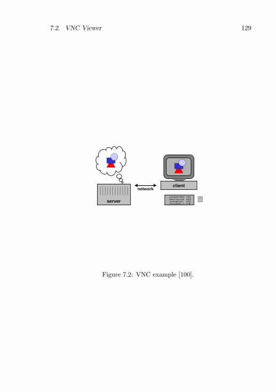
7.2. VNC Viewer 129
server
network
1 2 3 4 5 6 7 8 9 0q w e r t y u i o pa s d f g h j k l ;z x c v b n m , . /
7 8 94 5 61 2 30 dl
client
Figure 7.2: VNC example [100].

130 Chapter 7. Application Case Studies
tosh, Windows CE, Palm and other systems [76]. Most of these im-plementations communicate via TCP/IP, but any reliable streamingprotocol may be used.
To allow Aos users to use applications running on other operatingsystems, a VNC viewer (client) has been implemented, based on theVNC viewer for Oberon [58]. The viewer opens a window that displaysthe contents of the remote frame buffer (e.g., a Windows or Unix desk-top) running under control of a VNC server on another (possibly shared)computer. Local mouse movements and keyboard events directed to thewindow are transmitted to the server, and control the applications run-ning there. Remote display updates are transmitted by the server anddisplayed on the local machine.
The viewer implementation defines two types of active object: areceiver and a sender. The receiver receives display update events fromthe server and draws them in the window. The sender accepts localwindow events and sends mouse and keyboard events to the server.One instance of each of these objects is created for every VNC windowopened. The implementation allows multiple VNC connections to beopened.
For normal non-multimedia applications the viewer performs well,even in a low-bandwidth LAN (10Mbps). It can be used over modemconnections, but is not very responsive in this case. Multimedia applica-tions like video playback require a high-bandwidth connection (100Mbpsor more) for acceptable performance.
7.3 Other Applications
Except for the applications developed by the author and those portedfrom Native Oberon, several new applications have been developed byAos users. These demonstrate that Aos is a stable development envi-ronment.
Parallel compiler P. Reali developed a parallel Active Oberon com-piler [95] as part of his dissertation work [96]. The compiler isparallelized by instantiating an active object for the parsing andcode generation of each scope in the source program.
Java environment P. Reali and R. Laich developed a Java environ-ment with a just-in-time compiler [94, 102]. The Java runtime

7.3. Other Applications 131
system is implemented in terms of the Aos kernel. For example,Java processes are mapped to active objects.
Window manager T. Frey is developing a window manager and textsystem based on a general display model [40]. It uses active objectsto concurrently update the display.
VNC server T. Frey developed a VNC server (cf. 7.2) as plugin forthe window manager. The server allows an Aos system to beremote-controlled via the network and to operate without a phys-ical display.
Dynamic HTTP server T. Frey expanded the simple agent-basedweb server (cf. 6.2.2) into a complete HTTP 1.1 [36] server thatcan serve content dynamically generated by Active Oberon plug-ins.
FAT file system B. Egger developed a FAT file system for NativeOberon [35] and then ported it to Aos.
XML browser S. Walthert developed a general extended markup lan-guage (XML) toolkit and a XML/CSS browser [127]. The XMLtoolkit is used in the window manager and in the Aos configurationmodule.
Remote file system P. Studi developed a network file system [116]allowing Aos users to share files with a Unix system. The filesystem consists of a client running as an Aos file system plugin(cf. 6.1.1) and a server running on a Unix system. The clientand server communicate via a proprietary stateless TCP/IP-basedprotocol that can recover from interruptions in the network.
Medical image processing D. Keller is developing a medical imageprocessing server allowing Windows clients to store, process andretrieve medical images on an Aos server.
FTP server P. Reali and B. Egger developed an FTP server.

132 Chapter 7. Application Case Studies

Chapter 8
Evaluation
In this chapter the Aos system is evaluated in four ways: section 8.1makes a conceptual comparison with related operating systems, sec-tion 8.2 presents performance measurements, section 8.3 evaluates theportability and flexibility of the system and section 8.4 presents the sizesof the various subsystems.
8.1 Comparison with Related Systems
The flexible modular design of Aos makes it suitable for many differentapplication areas and hardware environments, ranging from small em-bedded systems, through personal computers, to multiprocessor work-stations and servers. Therefore, the system could be compared with awide range of related operating systems. In this section, however, we re-strict the comparison to a few shared-memory multiprocessor systems ofhistorical significance, and a few Unix-related systems that are typicallyused on commercial multiprocessor machines.
8.1.1 Multiprocessor Research Operating Systems
Hydra
Hydra [136, 137] is the kernel of a multiprocessor operating system de-veloped in the early seventies at Carnegie-Mellon University for theC.mmp shared memory multiprocessor. This machine was based on a
133

134 Chapter 8. Evaluation
number of PDP-11 minicomputers with a shared memory connected bya cross-bar switch.
The goal was to design a “collection of facilities of universal appli-cability and absolute reliability — a set of mechanisms from which anarbitrary set of operating system facilities can be conveniently, flexibly,efficiently and reliably constructed” [136]. This is the essential idea ofa kernel, also strived for in Aos.
A good example of the Hydra design goal to separate mechanismand policy is its protection mechanism. An object is the unit of protec-tion, and a capability, which is created and modified only by the kernel,references an object and defines which operations are valid on it. A callto a protected object is only possible via the kernel, which verifies thatthe capability allows the operation. The specific protection policy usedis not part of the kernel.
Open extensible systems like Oberon and Aos allow parts of thesystem to be replaced or extended easily. Consequently there is less needto explicitly separate mechanism and policy, as required for comparableflexibility in a microkernel design.
Hydra processes communicate and synchronize with each other withsimple message buffering primitives and Dijkstra-style semaphore op-erations. In Aos, processes communicate and synchronize by invokingactive object methods and passing references to shared data directly toeach other.
Firefly and Topaz
The Firefly [121] is a shared-memory multiprocessor workstation devel-oped at DEC SRC in the mid-eighties. Topaz, the associated softwaresystem, provides binary emulation of the Ultrix (Unix) system call in-terface.
Like Topaz, Aos can also be used in a multiprocessor workstationenvironment. Unlike Topaz, it does not attempt any level of applica-tion compatibility with Unix, except for client-server cooperation vianetwork protocols (cf. 6.2.2 and 7.2).
The Topaz system is structured as a microkernel. The kernel con-tains virtual memory management, thread scheduling, simple devicedrivers and the interprocess communication mechanism. The operatingsystem, file system and window manager run as user space services.

8.1. Comparison with Related Systems 135
The main advantages of a microkernel design are flexibility, pro-tection and well-defined interfaces between services. These goals areaddressed by other means in Aos. Flexibility is obtained with the useof modules and plugin objects. Hardware-based protection is deemedless important, because a type-safe language is used throughout, bothfor system and application programming. Well-defined interfaces areaccentuated even more by modules, and, in contrast to most microker-nels, are type-checked. There is no need for stub libraries to serializeand de-serialize parameters.
As is common in microkernel designs, the Topaz system separates thethread and address space concepts from the Unix (heavyweight) processconcept. This distinction is made mainly to reduce the cost of creat-ing processes (threads), so that server programs can service multiplerequests in parallel. Communication between different address spacesand machines is performed by remote procedure calls. In Aos, creatingan active object is similarly efficient, and servers can be programmedwith multiple active objects (cf. 6.2.2).
The kernel and system are written in the Modula-2+ language, whichextended Modula-2 with garbage collection, exception handling and con-currency. The applications perform reference counting (implemented bythe compiler), and the garbage collector runs concurrently with them,performing an additional conservative mark-sweep operation to handlestack pointers and cyclic structures. A Threads module provides con-dition variables for synchronization and the language provides a lockstatement for declaring critical regions.
Psyche
Psyche [108] is a parallel operating system that was developed at theUniversity of Rochester in the late eighties for the BBN Butterfly Plusmultiprocessor. The main emphasis was on experimenting with differentparallel computing models co-existing on the same system, especially inthe context of computer vision and robot control.
The Psyche kernel provides four abstractions: the realm, protectiondomain, virtual processor and process. A realm consists of code anddata and is comparable to an object. Each protection domain has itsown page tables, which map those realms that are accessible from thedomain. Processes are threads of control implemented and scheduled at

136 Chapter 8. Evaluation
user level. Virtual processors are implemented by the kernel, and areused to schedule the user-level processes.
Every realm is at a globally unique virtual address, which allowsprocesses to share pointers directly. An access to a realm not yet partof the current domain causes a page fault, allowing the kernel to checkwhether the access should be allowed. If an access is allowed, the realmis mapped into the invoking domain.
The bi-level scheduling allows different application-specific schedul-ing policies to be applied at user level and to co-exist. Software in-terrupts are used by the kernel to signal to a user-level scheduler im-plementation when scheduling decisions has to be made, e.g., when aprocess enters a new protection domain, or a timer expires.
In comparison, Aos provides only one kind of process and a singlelevel of scheduling. It is not clear if the flexibility of different co-existinguser-level scheduling policies in Psyche is really advantageous. If otherscheduling policies are required in Aos, they can be implemented bymodifying the Active module.
The Psyche kernel implementation uses four kinds of synchroniza-tion. Critical sections involving processor-local data structures are pro-tected by disabling preemption of virtual processors, and those involvingdevice handlers are protected by masking out interrupts. Other criticalsections of small, bounded length are protected with spin-locks, whichalso disable preemption of virtual processors to comply with the lengthbounds. Critical sections involving conditions that are not bounded intime are implemented with (blocking) semaphores. Synchronization atuser-level is under full control of the specific process scheduling imple-mentation used.
The synchronization mechanisms used in the Aos kernel implemen-tation are comparable to that of Psyche, except that semaphores arenot used directly. Instead, active object exclusive blocks and the awaitstatement are used for higher-level synchronization, also at the applica-tion (‘user’) level.
Hurricane
The University of Toronto’s Hurricane [122] system was developed in themid-nineties specifically to address the issue of scalability in large-scalemultiprocessor operating systems and runs on the prototype Hector mul-

8.1. Comparison with Related Systems 137
tiprocessor. It was argued that multiprocessor operating systems thatevolve from singleprocessor systems only address concurrency issues byidentifying and removing the most important bottlenecks, and do notaddress locality issues.
To address the scalability issue, a hierarchical clustering design isused, in which higher-level entities control resources in a coarse, globalfashion, and lower-level entities control resources in a finer, localizedway. Interaction between distant entities normally occurs at higherlevels of the hierarchy. A cluster in the Hurricane system consists of asmall-scale symmetric-multiprocessing microkernel sharing kernel dataand control structures among a few processors. In a large system, severalclusters are created to manage disjoint sets of ‘neighbouring’ processors,with replicated kernel structures. The clusters work together to presenta consistent view of the whole system to applications.
Tornado
The University of Toronto’s Tornado [42] system is the late ninetiesfollow-up of the Hurricane system, also conceived to address the issuesof locality and concurrency in shared-memory multiprocessor operatingsystems. It is implemented in C++ and runs on the Toronto NUMAchineand the SimOS simulator.
Tornado is structured in an object-oriented fashion and handles re-quests to different resources without accessing any common data struc-tures or locks. A generalization of the Hurricane system’s replicatedkernel structures, called clustered objects, is used to partition a kernelobject into different representative objects, which handle independentrequests to a resource on different processors by different representativeobjects. The kernel sees to it that repeated requests to a service objectby a client are serviced on the same processor as the client, and parallelrequests are automatically served by different service threads.
The Tornado authors note that there are two kinds of locking inmost systems: locks inherently related to concurrency control of shareddata structures, and locks related to providing an existence guaranteethat ensures that a data structure containing a variable is not deallo-cated during an update. They implemented a semi-automatic garbagecollector for clustered objects, which ensures that a reference to suchan object can be used at any time, even when no locks are held. They

138 Chapter 8. Evaluation
also claim that this removes a primary reason for holding locks acrossobject invocations, thereby increasing modularity.
The Tornado argument for garbage collection also holds for Aos. Inthe presence of a garbage collector, it is never necessary to hold a lockon an object reference solely to protect the object from deallocation byanother process while it is being used. Holding a reference is sufficientto ensure the existence of the object.
8.1.2 Unix and Related Operating Systems
Unix in all its flavours is the most widely-used server operating sys-tem on the Internet. Although the original system was developed forsingleprocessors, Unix has been adapted for multiprocessor machinesby various hardware vendors (e.g., Sun Solaris, SGI IRIX, IBM AIX,HP/UX) [16, 83, 106].
In this section we summarize implementation characteristics of someUnix-related operating systems, and make brief comparisons with Aos.Compared with the complexity of these large ‘real world’ systems, thetransparency of Aos promises to be an advantage in building reliable,secure, and efficient custom applications.
BSD
As a representative example of a Unix system we look at the influen-tial BSD (‘Berkeley Software Distribution’) system [65], which played amajor part in popularizing the internet protocols.
Structurally, Aos is very different from BSD, which has a conven-tional monolithic kernel design, with separation between user and kernel(privileged) mode. This separation protects the kernel from accidentalor malicious damage from applications, but also incurs overhead whenan application performs a system call, since a cross-domain call is re-quired, and often data has to be copied specially between user andkernel mode. In Aos, a kernel call is a normal procedure call to a kernelmodule.
Many facilities provided by the BSD kernel are also provided in Aos:memory management (in the Memory and Heap modules), interrupt andtrap handling (in the Interrupts module), processes, context switchingand time-slicing (in the Active module), and timing services (in the

8.1. Comparison with Related Systems 139
Kernel module). However, in Aos these facilities are reduced in scope.For example, there are no separate address spaces and virtual memory(and consequently no explicit shared memory management and mmapsystem call), processes are lightweight (there is little process-connectedstate and no process groups), there is no user and group management(permissions, quotas) in the kernel, and no explicit interprocess com-munication (procedure calls are used instead).
Many other concepts and facilities from the BSD kernel have equiv-alents in the Aos system.
The interface of the Disks module can be compared with the entrypoints of BSD block devices. Common to both interfaces are open, closeand size calls. Both interfaces also provide a function to initiate a datatransfer: Transfer in Aos, and the strategy entry point in BSD. However,the latter always initiates an asynchronous data transfer, while Aosalways uses synchronous transfers. This is done as they are deterministicand less error-prone to program, and experience in various microkernel-based systems have shown that synchronous transfers combined withlightweight processes are sufficiently powerful for most applications.
Like the BSD block buffer cache, the Cache object from the Cachesmodule acts as an intermediary between the file system and block devicedriver, caching read and write requests. An important difference is thatthe cache object is optional, and an application that wants full controlof a disk, e.g., a database system, can do so directly. In BSD, blockdevice drivers must additionally implement the so-called raw interfacefor this case.
The FS module is comparable to the file descriptor managementand vnode layer in BSD that manages file descriptors and provides anabstract interface to file system implementations. However, the Aosinterface is not encumbered with a tight coupling between processes andfile descriptors, and it focuses on persistent files, avoiding the unificationof network ‘sockets’ and file descriptors. Additionally, multiplexing ishandled by multiple active objects, obviating the need for additionalpolling, non-blocking or signalling interfaces.
Part of the reason why Unix processes carry a lot of state informationis to simplify resource management. When a process terminates, thekernel can deallocate all the related resources, e.g., memory and filedescriptors. In Aos, the system-wide garbage collector assumes thisresponsibility.

140 Chapter 8. Evaluation
Solaris
Sun Microsystems’ Solaris operating system, based on Unix System VRelease 4 and BSD, supports symmetric multiprocessing [64]. It runson singleprocessor machines and multiprocessors like the Sun Enterpriseseries with up to 64 processors. Here we focus briefly on processesand synchronization in the Solaris kernel. The rest of the kernel iscomparable to the BSD kernel presented above.
Solaris uses a three-level process model, with traditional heavyweightUnix processes and two kinds of lightweight processes: kernel threads(also called LWP for lightweight processes) and user-level threads. Thelatter are managed by a user-level thread library and are scheduledby using a shared pool of kernel-level threads to execute them. Kernelthreads can block during I/O operations (comparable to Psyche’s virtualprocessors).
The Solaris kernel is preemptable and several kernel threads canbe active in the kernel at the same time. It uses multiple synchro-nization mechanisms: mutex locks, reader/writer locks, dispatcher locks,semaphores and condition variables.
Several hundred lock instances are declared statically in the kernelsources, and several thousand locks can be created dynamically. Themost common kind of lock used in the kernel is the mutex lock, whichprotects a simple critical section.
Two kinds of mutex lock are available: spin locks and adaptive locks.Spin locks operate as described in section 5.4. Adaptive locks are sim-ilar, with the following difference: when a thread attempts to acquirean adaptive lock that is held by another thread currently running onanother processor, the first thread will spin waiting for the lock; other-wise, it will block. The reasoning is that it is likely that a lock held bya running thread will be released soon, as critical sections are normallyshort. Therefore it is not worth blocking the requesting thread andwaking it up again later. Another difference between the two kinds ofmutex lock is that adaptive locks may not be used in high level interrupthandlers, as they interact with the dispatcher (scheduler). Reportedly,the blocking case for adaptive locks rarely occurs.
When a mutex lock is released, and other threads are waiting to enterthe critical section, Solaris 7 wakes up all the waiting threads at the sametime. Earlier versions of Solaris only woke up one waiting thread, but
8.1. Comparison with Related Systems 141
this was found to complicate the code unnecessarily. Potentially theSolaris 7 behaviour can lead to the so-called thundering herd problem,where many woken threads waste processing time competing in vain forthe lock, because only one can acquire it. Extensive testing has shownthat this does not occur in practice, because critical regions protectedwith mutex locks are normally very short. Solaris does not transfer thelock directly to one of the waiting threads, because this would defeatthe purpose of adaptive locks. If another thread attempts to acquirethe lock before a woken thread is scheduled to run again, it can find thelock free and quickly enter and leave the short critical section. In caseof a direct transfer, the new thread would have to block and be wokenagain later.
Reader/writer locks are used when there is a need to distinguish be-tween read and write access to a shared data structure. At any time,several reading threads may be present in a critical section, or alterna-tively, one writing thread. These locks differ from mutex locks in theirwakeup behaviour. If reader threads are waiting when a lock is released,all the waiting readers are woken, and if writers are waiting, only thefirst writer in the queue is woken. Additionally, the kernel does a directtransfer of the lock to the woken reader threads or writer thread. Thereasoning is that this kind of lock is used for longer critical sections thanthe mutex locks.
The third kind of lock used in the Solaris kernel is the dispatcherlock. This lock has a simple implementation and is used to protectedthe scheduler and locking data structures. The first form of the lockis a normal spin lock implementation with no blocking option, and thesecond form additionally masks out low-level interrupts. High-level (re-altime) interrupts are allowed to interrupt the scheduler, but their inter-rupt handlers are not allowed to invoke the scheduler. The dispatcherlock data structure is simply a byte flag indicating if the lock is held ornot.
In addition to the three kinds of locks presented above, the kerneluses integer semaphores. The semaphore release operation is similar tothe reader/writer lock release operation in that it wakes up only onewaiting thread. Semaphores are only used in the buffer I/O module,the kernel module loader and a couple of device drivers.
The Solaris kernel uses condition variables in combination with mu-tex locks to perform process synchronization. Three operations are de-
142 Chapter 8. Evaluation
fined on condition variables: wait, signal and broadcast. The wait opera-tion puts the calling process to sleep by removing its descriptor from thescheduler queue and adding it to a queue associated with the conditionvariable. The signal and broadcast operations remove processes fromthe condition variable queue and add them to the scheduler queue sothey can run again. The signal operation removes one process, and thebroadcast operation removes all processes that are waiting. The waitoperation has some variations for different exception handling, prioritycontrol and time-out options.
It is interesting to study the evolution of the synchronization mech-anism implementation in Solaris releases [64]. The kernel has benefittedfrom extensive testing over the years, and it is clear to see that the trendis towards more compact and efficient implementation of synchroniza-tion primitives like mutex locks.
Windows 2000
Microsoft’s premier operating system, Windows 2000 (formerly namedWindows NT), supports symmetrical multiprocessing and runs on sin-gleprocessor and multiprocessor Intel IA-32 machines [114].
Structurally, Windows 2000 is similar to Unix. It has a monolithickernel that includes operating system services such as memory manage-ment, process management, I/O, interprocess communication, and alsoincludes device drivers and the windowing, user-interface and graphicssubsystems. Applications and some system services run as processes inuser mode.
The kernel is divided into two layers: the executive and the kernelproper. The executive contains system service functions, some of whichare exported to applications, and others that are only callable fromwithin the kernel. The main services provided by the executive are:configuration manager, process and thread manager, security referencemanager, plug-and-play device manager, power manager, instrumen-tation manager, cache manager, virtual memory manager, object man-ager, interprocess communication facility, run-time library functions andvarious executive support functions. The kernel proper provides funda-mental services such as thread scheduling, synchronization and low-levelhardware support.
For mutual exclusion inside critical sections, the kernel uses spin

8.1. Comparison with Related Systems 143
locks. A few core data structures of the kernel are protected with queuedspin locks. These are spin locks with a waiting queue, which storesprocessors waiting for the lock. When a processor releases the lock, ithands the lock over to the next waiting processor. Queued spin locksdo not access a shared cache line during busy waiting [103].
The Windows 2000 process model is akin to that of Solaris. Heavy-weight processes act primarily as resource containers, and have separateaddress spaces. Threads are kernel-level lightweight processes that canshare the address space of a process. Kernel processes and threads arecomplex objects — a process record has approximately 200 data fields,and a thread record approximately 180 (excluding sub-structures beingpointed to). For comparison, the Aos process record (cf. 5.9.2) containsabout 20 fields.
For thread synchronization, the kernel uses several kinds of so-calleddispatcher objects: mutex, semaphore, queue, event, timer, process,thread and file. Each object has an associated signalling conditionwhich changes according to the state changes of the object itself. Forexample, a queue object is signalled when an item is placed on thequeue, and a timer object is signalled when a certain time interval haselapsed. A thread that executes a wait operation on a dispatcher objectis suspended until the associated condition is signalled. Optionally, thethread can specify a maximum time it is prepared to wait, and it is pos-sible to wait on multiple objects simultaneously. The approach takenby Windows is apparently to provide the most common synchroniza-tion scenarios pre-programmed as different kinds of dispatcher objects.In Aos, synchronization scenarios corresponding to those provided byWindows dispatcher objects can be programmed directly using the awaitprimitive.
In Windows, as in Unix, kernel-mode code has complete access tosystem memory and device drivers run in kernel mode. This is notinherently a problem, but drivers are commonly written entirely in anunsafe language (C and assembler) and erroneous device drivers are themost common cause of system failure. Windows 2000 addresses thisvulnerability using a driver certification mechanism. This mechanismwarns the user when a third-party driver is installed that has not beenauthorized (and tested) by Microsoft, under the assumption that suchdrivers are less reliable [9].
Aos is also vulnerable to this problem, but at least drivers are largely

144 Chapter 8. Evaluation
implemented in a safe language, which excludes whole classes of possibleerrors. Furthermore, it is presumed that the vastly simpler kernel re-duces the complexity of writing drivers, and consequently, the likelihoodof errors.
8.2 Performance Measurements
The main reason for utilizing shared-memory multiprocessors is to im-prove application performance by parallel processing. Therefore, itis especially important for a multiprocessor operating system to per-form well, otherwise the potential improvement through parallelizationis wasted.
Although good performance is the ultimate goal of a multiprocessoroperating system, providing a stable and reliable system should be theprimary mission of any operating system developer, who must guardagainst unnecessarily complicating the design and implementation forthe sake of performance. In short, performance is important, but shouldnever come at the cost of dependability.
To see how Aos compares with an established operating system, mi-crobenchmarks were used to compare selected parts of the Aos kernelwith corresponding parts of a Unix kernel. The version of Unix usedfor the comparisons is Linux, which is widely deployed and highly opti-mized, due to its open source distributed development model.
A microbenchmark is a simple program that exercises a specific partof a system. Microbenchmarks are not always an ideal tool for compar-ing systems, because they are not realistic applications [12]. Nonethe-less, their simplicity gives them the advantage that they can be usedto compare specific system characteristics, when used carefully. Mi-crobenchmark results can be useful even in isolation, since they providean estimate of the performance of a specific part of the system, whichcan aid the development of efficient applications.
As Aos and Linux do not share common programming interfaces andmodels, approximately equivalent benchmark programs were developedin Active Oberon for Aos, and in C for Linux. Where active objects areused in the Aos benchmarks, Posix threads (not heavyweight processes)are used in the Linux benchmarks.
All performance measurements were run on a dual-boot Dell Power-Edge 8450 with 6 Pentium III Xeon processors running at 700MHz, each
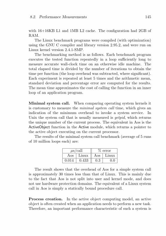
8.2. Performance Measurements 145
with 16+16KB L1 and 1MB L2 cache. The configuration had 2GB ofRAM.
The Linux benchmark programs were compiled (with optimization)using the GNU C compiler and library version 2.95.2, and were run onLinux kernel version 2.4.1-SMP.
The benchmarking method is as follows. Each benchmark programexecutes the tested function repeatedly in a loop sufficiently long tomeasure accurate wall-clock time on an otherwise idle machine. Thetotal elapsed time is divided by the number of iterations to obtain thetime per function (the loop overhead was subtracted, where significant).Each experiment is repeated at least 5 times and the arithmetic mean,standard deviation and percentage error are computed for the results.The mean time approximates the cost of calling the function in an innerloop of an application program.
Minimal system call. When comparing operating system kernels itis customary to measure the minimal system call time, which gives anindication of the minimum overhead to invoke a system service. InUnix the system call that is usually measured is getpid, which returnsthe unique number of the current process. The equivalent in Aos is theActiveObject function in the Active module, which returns a pointer tothe active object executing on the current processor.
The results of the minimal system call benchmark (average of 5 runsof 10 million loops each) are:
µs/call % errorAos Linux Aos Linux
0.014 0.433 0.3 0.0
The result shows that the overhead of Aos for a simple system callis approximately 30 times less than that of Linux. This is mainly dueto the fact that Aos is not split into user and kernel mode, and doesnot use hardware protection domains. The equivalent of a Linux systemcall in Aos is simply a statically bound procedure call.
Process creation. In the active object computing model, an activeobject is often created when an application needs to perform a new task.Therefore, an important performance characteristic of such a system is

146 Chapter 8. Evaluation
10 100 1000 10000
active objects (threads)
0
20
40
60
80
100
120
µs/
crea
te
........ Aos
..
..
..
..
..
..
..
..
..
..
..
..
..
..
..
..
..
..
..
..
..
..
..
..
..
..
..
..
..
..
..
..
..
..
..
..
..
..
..
..
..
..
..
..
..
..
..
..
..
..
..
..
..
..
..
..
..
..
..
..
..
..
..
..
..
..
..
..
..
..
..
..
..
..
..
..
..
..
..
..
..
..
..
..
..
..
..
..
..
..
..
..
..
..
..
..
..
..
..
..
..
..
..
..
..
..
..
..
..
..
..
..
..
..
..
..
..
..
..
..
..
..
..
..
..
..
..
..
..
..
..
..
..
..
..
..
..
..
..
..
..
..
..
..
..
..
..
..
..
..
..
..
..
..
..
..
..
..
..
..
..
..
..
..
..
..
..
..
..
..
..
..
..
..
..
..
..
..
..
..
..
..
..
..
..
..
..
..
..
..
..
..
..
..
..
..
..
..
..
..
..
..
..
..
..
..
..
..
..
..
..
..
..
..
..
..
..
..
..
..
..
..
..
..
..
..
..
..
..
..
..
..
..
..
..
..
..
..
..
..
Linux
N/A
Figure 8.1: Aos active object and Linux thread creation time.
the time taken to create and destroy an active object. The equivalentin a conventional system is the time it takes to create and destroy alightweight process.
The Aos version of the process creation benchmark defines an activeobject that does nothing except set a flag showing that it is terminating,and then terminates. It provides a Join method that can be called towait until the termination flag is set. The main loop of the benchmarkcreates a number of such active objects, and then calls the Join methodof each active object in turn to synchronize with its termination. Thetime measured includes this synchronization, the allocation of the activeobject, the invocation of its initializer, the creation of its process andthe context switch to and from its process.
The Linux version of the benchmark uses the LinuxThreads imple-mentation of Posix threads, included in the GNU C library. The bench-mark creates a thread (with pthread create), which does nothing butterminate itself (with pthread exit). The main loop of the benchmarkcreates a number of such threads, and then calls pthread join to synchro-nize with the termination of each thread. The time measured includesthe clone system call to create the thread, the exit system call to termi-nate the thread and the wait system call to wait for the termination.
The results of the process creation benchmark (average of 50 runs)
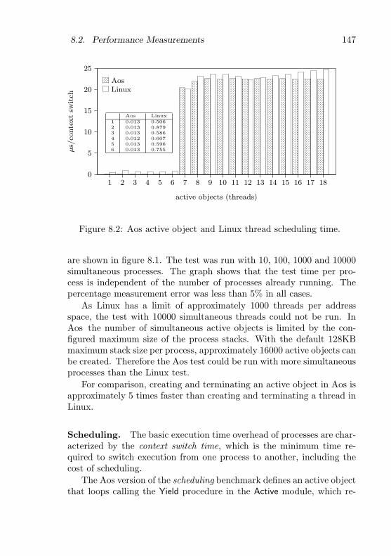
8.2. Performance Measurements 147
1 2 3 4 5 6 7 8 9 10 11 12 13 14 15 16 17 18
active objects (threads)
0
5
10
15
20
25µs/
conte
xt
switch
........ Aos
..
..
..
..
..
..
..
..
..
..
..
..
..
..
..
..
..
..
.
..
..
..
..
..
..
..
..
..
..
..
..
..
..
..
..
..
..
.
..
..
..
..
..
..
..
..
..
..
..
..
..
..
..
..
..
..
.
..
..
..
..
..
..
..
..
..
..
..
..
..
..
..
..
..
..
.
..
..
..
..
..
..
..
..
..
..
..
..
..
..
..
..
..
..
.
..
..
..
..
..
..
..
..
..
..
..
..
..
..
..
..
..
..
..
.
..
..
..
..
..
..
..
..
..
..
..
..
..
..
..
..
..
..
..
..
..
..
..
..
..
..
..
..
..
..
..
..
..
..
..
..
..
..
..
.
..
..
..
..
..
..
..
..
..
..
..
..
..
..
..
..
..
..
..
..
..
..
..
..
..
..
..
..
..
..
..
..
..
..
..
..
..
..
..
.
..
..
..
..
..
..
..
..
..
..
..
..
..
..
..
..
..
..
..
..
.
..
..
..
..
..
..
..
..
..
..
..
..
..
..
..
..
..
..
..
..
.
..
..
..
..
..
..
..
..
..
..
..
..
..
..
..
..
..
..
..
..
.
..
..
..
..
..
..
..
..
..
..
..
..
..
..
..
..
..
..
..
..
.
..
..
..
..
..
..
..
..
..
..
..
..
..
..
..
..
..
..
..
..
..
..
..
..
..
..
..
..
..
..
..
..
..
..
..
..
..
..
..
..
.
..
..
..
..
..
..
..
..
..
..
..
..
..
..
..
..
..
..
..
..
..
..
..
..
..
..
..
..
..
..
..
..
..
..
..
..
..
..
..
..
.
..
..
..
..
..
..
..
..
..
..
..
..
..
..
..
..
..
..
..
..
.
..
..
..
..
..
..
..
..
..
..
..
..
..
..
..
..
..
..
..
..
.
..
..
..
..
..
..
..
..
..
..
..
..
..
..
..
..
..
..
..
..
.
..
..
..
..
..
..
..
..
..
..
..
..
..
..
..
..
..
..
..
..
.
..
..
..
..
..
..
..
..
..
..
..
..
..
..
..
..
..
..
..
..
.
..
..
..
..
..
..
..
..
..
..
..
..
..
..
..
..
..
..
..
..
..
..
..
..
..
..
..
..
..
..
..
..
..
..
..
..
..
..
..
..
.
..
..
..
..
..
..
..
..
..
..
..
..
..
..
..
..
..
..
..
..
..
..
..
..
..
..
..
..
..
..
..
..
..
..
..
..
..
..
..
..
.
..
..
..
..
..
..
..
..
..
..
..
..
..
..
..
..
..
..
..
..
.
..
..
..
..
..
..
..
..
..
..
..
..
..
..
..
..
..
..
..
..
.
..
..
..
..
..
..
..
..
..
..
..
..
..
..
..
..
..
..
..
..
.
..
..
..
..
..
..
..
..
..
..
..
..
..
..
..
..
..
..
..
..
.
..
..
..
..
..
..
..
..
..
..
..
..
..
..
..
..
..
..
..
..
.
..
..
..
..
..
..
..
..
..
..
..
..
..
..
..
..
..
..
..
..
.
..
..
..
..
..
..
..
..
..
..
..
..
..
..
..
..
..
..
..
..
..
..
..
..
..
..
..
..
..
..
..
..
..
..
..
..
..
..
..
..
.
..
..
..
..
..
..
..
..
..
..
..
..
..
..
..
..
..
..
..
..
..
..
..
..
..
..
..
..
..
..
..
..
..
..
..
..
..
..
..
..
.
..
..
..
..
..
..
..
..
..
..
..
..
..
..
..
..
..
..
..
..
.
..
..
..
..
..
..
..
..
..
..
..
..
..
..
..
..
..
..
..
..
.
..
..
..
..
..
..
..
..
..
..
..
..
..
..
..
..
..
..
..
..
.
..
..
..
..
..
..
..
..
..
..
..
..
..
..
..
..
..
..
..
..
.
..
..
..
..
..
..
..
..
..
..
..
..
..
..
..
..
..
..
..
..
..
..
..
..
..
..
..
..
..
..
..
..
..
..
..
..
..
..
..
..
.
..
..
..
..
..
..
..
..
..
..
..
..
..
..
..
..
..
..
..
..
..
..
..
..
..
..
..
..
..
..
..
..
..
..
..
..
..
..
..
..
.
..
..
..
..
..
..
..
..
..
..
..
..
..
..
..
..
..
..
..
..
..
..
..
..
..
..
..
..
..
..
..
..
..
..
..
..
..
..
..
..
.
..
..
..
..
..
..
..
..
..
..
..
..
..
..
..
..
..
..
..
..
..
..
..
..
..
..
..
..
..
..
..
..
..
..
..
..
..
..
..
..
.
..
..
..
..
..
..
..
..
..
..
..
..
..
..
..
..
..
..
..
..
..
..
..
..
..
..
..
..
..
..
..
..
..
..
..
..
..
..
..
..
.
..
..
..
..
..
..
..
..
..
..
..
..
..
..
..
..
..
..
..
..
..
..
..
..
..
..
..
..
..
..
..
..
..
..
..
..
..
..
..
..
.
..
..
..
..
..
..
..
..
..
..
..
..
..
..
..
..
..
..
..
..
Linux
Aos Linux1 0.013 0.5062 0.013 0.8793 0.013 0.5864 0.012 0.6075 0.013 0.5966 0.013 0.755
Figure 8.2: Aos active object and Linux thread scheduling time.
are shown in figure 8.1. The test was run with 10, 100, 1000 and 10000simultaneous processes. The graph shows that the test time per pro-cess is independent of the number of processes already running. Thepercentage measurement error was less than 5% in all cases.
As Linux has a limit of approximately 1000 threads per addressspace, the test with 10000 simultaneous threads could not be run. InAos the number of simultaneous active objects is limited by the con-figured maximum size of the process stacks. With the default 128KBmaximum stack size per process, approximately 16000 active objects canbe created. Therefore the Aos test could be run with more simultaneousprocesses than the Linux test.
For comparison, creating and terminating an active object in Aos isapproximately 5 times faster than creating and terminating a thread inLinux.
Scheduling. The basic execution time overhead of processes are char-acterized by the context switch time, which is the minimum time re-quired to switch execution from one process to another, including thecost of scheduling.
The Aos version of the scheduling benchmark defines an active objectthat loops calling the Yield procedure in the Active module, which re-

148 Chapter 8. Evaluation
leases the processor to another process that is ready to run. The mainprocedure of the benchmark creates a number of such active objects,and then pauses for a fixed number of seconds while the test objectsrun. Then it sets a global flag requesting the test objects to terminate,and synchronizes with their termination, similar to the process creationbenchmark. Each test object counts the number of times it has looped,and from this the average time per context switch is computed.
The Linux version of the benchmark is similar, except that it cre-ates Posix threads, and uses the sched yield system call to release theprocessor.
The results of the scheduling benchmark (average of 5 runs) areshown in figure 8.2. The test was run with 1 to 18 simultaneous pro-cesses. Once again, the graph shows that the test time per process isindependent of the number of processes already running. The percent-age measurement error was less than 1%, except in the first 6 cases,where the Linux test showed a measurement error of up to 15%.
The measurements with up to six processes shows a special caseof scheduling — when there are enough processors to service all readyprocesses (the test machine has six processors). The Aos and Linuxschedulers test for this common case and avoid any additional work bydirectly returning to the current process. Consequently these cases arephenomenally faster than the rest — by a factor 1700 in Aos and factor35 in Linux. The reason for the excellent performance of the special casein Aos is that it consists of a single test of an integer variable, which ispre-computed cheaply during normal operation. In Linux, the requiredparameter is not available directly, and has to be computed by loopingover the per-processor data structures.
The results show that when the system is under light load (the ex-ceptional case described above), the Aos scheduler is up to 60 timesfaster than Linux. When the system is under heavier load, the time perreschedule and context switch is roughly the same for Aos and Linux.The latter case could possibly be improved in Aos by splitting the sched-uler critical section, thereby increasing the potential parallelism.
Locking. Using multiple processes can speed up an application,because it increases the potential parallelism. However, the applicationpays a price for this parallelism, in the form of locking overhead forcritical sections in the manipulation of shared resources used by the
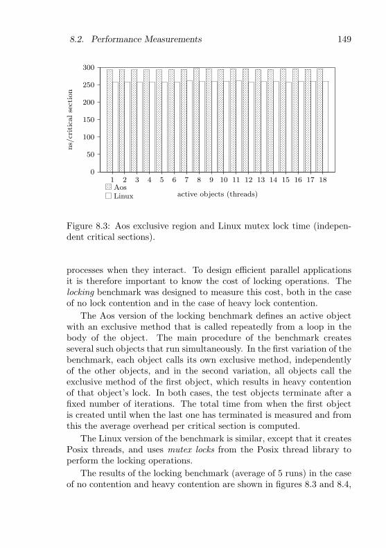
8.2. Performance Measurements 149
1 2 3 4 5 6 7 8 9 10 11 12 13 14 15 16 17 18
active objects (threads)
0
50
100
150
200
250
300ns/
critic
alse
ctio
n
........ Aos
..
..
..
..
..
..
..
..
..
..
..
..
..
..
..
..
..
..
..
..
..
..
..
..
..
..
..
..
..
..
..
..
..
..
..
..
..
..
..
..
..
..
..
..
..
..
..
..
..
..
..
..
..
..
..
..
..
..
..
..
..
..
..
..
..
..
..
..
..
..
..
..
..
..
..
..
..
..
..
..
..
..
..
..
..
..
..
..
..
..
..
..
..
..
..
..
..
..
..
..
..
..
..
..
..
..
..
..
..
..
..
..
..
..
..
..
..
..
..
..
..
..
..
..
..
..
..
..
..
..
..
..
..
..
..
..
..
..
..
..
..
..
..
..
..
..
..
..
..
..
..
..
..
..
..
..
..
..
..
..
..
..
..
..
..
..
..
..
..
..
..
..
..
..
..
..
..
..
..
..
..
..
..
..
..
..
..
..
..
..
..
..
..
..
..
..
..
..
..
..
..
..
..
..
..
..
..
..
..
..
..
..
..
..
..
..
..
..
..
..
..
..
..
..
..
..
..
..
..
..
..
..
..
..
..
..
..
..
..
..
..
..
..
..
..
..
..
..
..
..
..
..
..
..
..
..
..
..
..
..
..
..
..
..
..
..
..
..
..
..
..
..
..
..
..
..
..
..
..
..
..
..
..
..
..
..
..
..
..
..
..
..
..
..
..
..
..
..
..
..
..
..
..
..
..
..
..
..
..
..
..
..
..
..
..
..
..
..
..
..
..
..
..
..
..
..
..
..
..
..
..
..
..
..
..
..
..
..
..
..
..
..
..
..
..
..
..
..
..
..
..
..
..
..
..
..
..
..
..
..
..
..
..
..
..
..
..
..
..
..
..
..
..
..
..
..
..
..
..
..
..
..
..
..
..
..
..
..
..
..
..
..
..
..
..
..
..
..
..
..
..
..
..
..
..
..
..
..
..
..
..
..
..
..
..
..
..
..
..
..
..
..
..
..
..
..
..
..
..
..
..
..
..
..
..
..
..
..
..
..
..
..
..
..
..
..
..
..
..
..
..
..
..
..
..
..
..
..
..
..
..
..
..
..
..
..
..
..
..
..
..
..
..
..
..
..
..
..
..
..
..
..
..
..
..
..
..
..
..
..
..
..
..
..
..
..
..
..
..
..
..
..
..
..
..
..
.
..
..
..
..
..
..
..
..
..
..
..
..
..
..
..
..
..
..
..
..
..
..
..
..
..
..
..
..
..
..
..
..
..
..
..
..
..
..
..
..
..
..
..
..
.
..
..
..
..
..
..
..
..
..
..
..
..
..
..
..
..
..
..
..
..
..
..
..
..
..
..
..
..
..
..
..
..
..
..
..
..
..
..
..
..
..
..
..
..
.
..
..
..
..
..
..
..
..
..
..
..
..
..
..
..
..
..
..
..
..
..
..
..
..
..
..
..
..
..
..
..
..
..
..
..
..
..
..
..
..
..
..
..
..
.
..
..
..
..
..
..
..
..
..
..
..
..
..
..
..
..
..
..
..
..
..
..
..
..
..
..
..
..
..
..
..
..
..
..
..
..
..
..
..
..
..
..
..
..
.
..
..
..
..
..
..
..
..
..
..
..
..
..
..
..
..
..
..
..
..
..
..
..
..
..
..
..
..
..
..
..
..
..
..
..
..
..
..
..
..
..
..
..
..
.
..
..
..
..
..
..
..
..
..
..
..
..
..
..
..
..
..
..
..
..
..
..
..
..
..
..
..
..
..
..
..
..
..
..
..
..
..
..
..
..
..
..
..
..
.
..
..
..
..
..
..
..
..
..
..
..
..
..
..
..
..
..
..
..
..
..
..
..
..
..
..
..
..
..
..
..
..
..
..
..
..
..
..
..
..
..
..
..
..
.
..
..
..
..
..
..
..
..
..
..
..
..
..
..
..
..
..
..
..
..
..
..
..
..
..
..
..
..
..
..
..
..
..
..
..
..
..
..
..
..
..
..
..
..
.
..
..
..
..
..
..
..
..
..
..
..
..
..
..
..
..
..
..
..
..
..
..
..
..
..
..
..
..
..
..
..
..
..
..
..
..
..
..
..
..
..
..
..
..
..
..
..
..
..
..
..
..
..
..
..
..
..
..
..
..
..
..
..
..
..
..
.
..
..
..
..
..
..
..
..
..
..
..
..
..
..
..
..
..
..
..
..
..
..
..
..
..
..
..
..
..
..
..
..
..
..
..
..
..
..
..
..
..
..
..
..
.
..
..
..
..
..
..
..
..
..
..
..
..
..
..
..
..
..
..
..
..
..
..
.
..
..
..
..
..
..
..
..
..
..
..
..
..
..
..
..
..
..
..
..
..
..
..
..
..
..
..
..
..
..
..
..
..
..
..
..
..
..
..
..
..
..
..
..
.
..
..
..
..
..
..
..
..
..
..
..
..
..
..
..
..
..
..
..
..
..
..
..
..
..
..
..
..
..
..
..
..
..
..
..
..
..
..
..
..
..
..
..
..
.
..
..
..
..
..
..
..
..
..
..
..
..
..
..
..
..
..
..
..
..
..
..
..
..
..
..
..
..
..
..
..
..
..
..
..
..
..
..
..
..
..
..
..
..
.
..
..
..
..
..
..
..
..
..
..
..
..
..
..
..
..
..
..
..
..
..
..
..
..
..
..
..
..
..
..
..
..
..
..
..
..
..
..
..
..
..
..
..
..
.
..
..
..
..
..
..
..
..
..
..
..
..
..
..
..
..
..
..
..
..
..
..
..
..
..
..
..
..
..
..
..
..
..
..
..
..
..
..
..
..
..
..
..
..
.
..
..
..
..
..
..
..
..
..
..
..
..
..
..
..
..
..
..
..
..
..
..
..
..
..
..
..
..
..
..
..
..
..
..
..
..
..
..
..
..
..
..
..
..
.
..
..
..
..
..
..
..
..
..
..
..
..
..
..
..
..
..
..
..
..
..
..
..
..
..
..
..
..
..
..
..
..
..
..
..
..
..
..
..
..
..
..
..
..
.
..
..
..
..
..
..
..
..
..
..
..
..
..
..
..
..
..
..
..
..
..
..
..
..
..
..
..
..
..
..
..
..
..
..
..
..
..
..
..
..
..
..
..
..
.
..
..
..
..
..
..
..
..
..
..
..
..
..
..
..
..
..
..
..
..
..
..
..
..
..
..
..
..
..
..
..
..
..
..
..
..
..
..
..
..
..
..
..
..
..
..
..
..
..
..
..
..
..
..
..
..
..
..
..
..
..
..
..
..
..
..
.
..
..
..
..
..
..
..
..
..
..
..
..
..
..
..
..
..
..
..
..
..
..
..
..
..
..
..
..
..
..
..
..
..
..
..
..
..
..
..
..
..
..
..
..
.
..
..
..
..
..
..
..
..
..
..
..
..
..
..
..
..
..
..
..
..
..
..
.
..
..
..
..
..
..
..
..
..
..
..
..
..
..
..
..
..
..
..
..
..
..
..
..
..
..
..
..
..
..
..
..
..
..
..
..
..
..
..
..
..
..
..
..
.
..
..
..
..
..
..
..
..
..
..
..
..
..
..
..
..
..
..
..
..
..
..
..
..
..
..
..
..
..
..
..
..
..
..
..
..
..
..
..
..
..
..
..
..
.
..
..
..
..
..
..
..
..
..
..
..
..
..
..
..
..
..
..
..
..
..
..
..
..
..
..
..
..
..
..
..
..
..
..
..
..
..
..
..
..
..
..
..
..
.
..
..
..
..
..
..
..
..
..
..
..
..
..
..
..
..
..
..
..
..
..
..
..
..
..
..
..
..
..
..
..
..
..
..
..
..
..
..
..
..
..
..
..
..
.
..
..
..
..
..
..
..
..
..
..
..
..
..
..
..
..
..
..
..
..
..
..
..
..
..
..
..
..
..
..
..
..
..
..
..
..
..
..
..
..
..
..
..
..
.
..
..
..
..
..
..
..
..
..
..
..
..
..
..
..
..
..
..
..
..
..
..
..
..
..
..
..
..
..
..
..
..
..
..
..
..
..
..
..
..
..
..
..
..
.
..
..
..
..
..
..
..
..
..
..
..
..
..
..
..
..
..
..
..
..
..
..
Linux
Figure 8.3: Aos exclusive region and Linux mutex lock time (indepen-dent critical sections).
processes when they interact. To design efficient parallel applicationsit is therefore important to know the cost of locking operations. Thelocking benchmark was designed to measure this cost, both in the caseof no lock contention and in the case of heavy lock contention.
The Aos version of the locking benchmark defines an active objectwith an exclusive method that is called repeatedly from a loop in thebody of the object. The main procedure of the benchmark createsseveral such objects that run simultaneously. In the first variation of thebenchmark, each object calls its own exclusive method, independentlyof the other objects, and in the second variation, all objects call theexclusive method of the first object, which results in heavy contentionof that object’s lock. In both cases, the test objects terminate after afixed number of iterations. The total time from when the first objectis created until when the last one has terminated is measured and fromthis the average overhead per critical section is computed.
The Linux version of the benchmark is similar, except that it createsPosix threads, and uses mutex locks from the Posix thread library toperform the locking operations.
The results of the locking benchmark (average of 5 runs) in the caseof no contention and heavy contention are shown in figures 8.3 and 8.4,
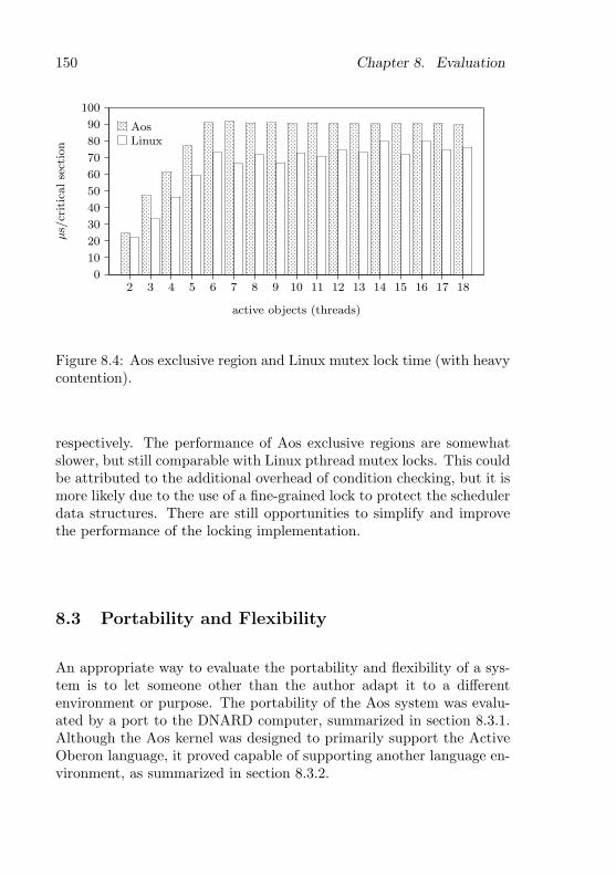
150 Chapter 8. Evaluation
2 3 4 5 6 7 8 9 10 11 12 13 14 15 16 17 18
active objects (threads)
0
10
20
30
40
50
60
70
80
90
100
µs/
critic
alse
ctio
n
........ Aos
..
..
..
..
..
.
..
..
..
..
..
.
..
..
..
..
..
.
..
..
..
..
..
.
..
..
..
..
..
..
..
..
..
..
.
..
..
..
..
..
..
..
..
..
..
.
..
..
..
..
..
..
..
..
..
..
.
..
..
..
..
..
..
..
..
..
..
.
..
..
..
..
..
..
..
..
..
..
..
..
..
..
..
..
..
..
..
..
..
..
..
..
..
..
..
.
..
..
..
..
..
..
..
..
..
..
..
..
..
..
..
..
..
..
..
..
..
..
..
..
..
..
..
.
..
..
..
..
..
..
..
..
..
..
..
..
..
..
..
..
..
..
..
..
..
..
..
..
..
..
..
..
..
..
..
.
..
..
..
..
..
..
..
..
..
..
..
..
..
..
..
..
..
.
..
..
..
..
..
..
..
..
..
..
..
..
..
..
..
..
..
.
..
..
..
..
..
..
..
..
..
..
..
..
..
..
..
..
..
.
..
..
..
..
..
..
..
..
..
..
..
..
..
..
..
..
..
..
..
..
.
..
..
..
..
..
..
..
..
..
..
..
..
..
..
..
..
..
..
..
..
.
..
..
..
..
..
..
..
..
..
..
..
..
..
..
..
..
..
..
..
..
.
..
..
..
..
..
..
..
..
..
..
..
..
..
..
..
..
..
..
..
..
.
..
..
..
..
..
..
..
..
..
..
..
..
..
..
..
..
..
..
..
..
.
..
..
..
..
..
..
..
..
..
..
..
..
..
..
..
..
..
..
..
..
.
..
..
..
..
..
..
..
..
..
..
..
..
..
..
..
..
..
..
..
..
..
..
..
..
..
..
..
..
..
..
..
..
..
..
..
..
..
..
..
..
..
.
..
..
..
..
..
..
..
..
..
..
..
..
..
..
..
..
..
..
..
..
..
..
..
..
..
..
..
..
..
..
..
..
..
..
..
..
..
..
..
..
..
.
..
..
..
..
..
..
..
..
..
..
..
..
..
..
..
..
..
..
..
..
.
..
..
..
..
..
..
..
..
..
..
..
..
..
..
..
..
..
..
..
..
.
..
..
..
..
..
..
..
..
..
..
..
..
..
..
..
..
..
..
..
..
.
..
..
..
..
..
..
..
..
..
..
..
..
..
..
..
..
..
..
..
..
.
..
..
..
..
..
..
..
..
..
..
..
..
..
..
..
..
..
..
..
..
.
..
..
..
..
..
..
..
..
..
..
..
..
..
..
..
..
..
..
..
..
.
..
..
..
..
..
..
..
..
..
..
..
..
..
..
..
..
..
..
..
..
.
..
..
..
..
..
..
..
..
..
..
..
..
..
..
..
..
..
..
..
..
.
..
..
..
..
..
..
..
..
..
..
..
..
..
..
..
..
..
..
..
..
.
..
..
..
..
..
..
..
..
..
..
..
..
..
..
..
..
..
..
..
..
.
..
..
..
..
..
..
..
..
..
..
..
..
..
..
..
..
..
..
..
..
.
..
..
..
..
..
..
..
..
..
..
..
..
..
..
..
..
..
..
..
..
.
..
..
..
..
..
..
..
..
..
..
..
..
..
..
..
..
..
..
..
..
.
..
..
..
..
..
..
..
..
..
..
..
..
..
..
..
..
..
..
..
..
.
..
..
..
..
..
..
..
..
..
..
..
..
..
..
..
..
..
..
..
..
.
..
..
..
..
..
..
..
..
..
..
..
..
..
..
..
..
..
..
..
..
.
..
..
..
..
..
..
..
..
..
..
..
..
..
..
..
..
..
..
..
..
.
..
..
..
..
..
..
..
..
..
..
..
..
..
..
..
..
..
..
..
..
.
..
..
..
..
..
..
..
..
..
..
..
..
..
..
..
..
..
..
..
..
.
..
..
..
..
..
..
..
..
..
..
..
..
..
..
..
..
..
..
..
..
.
..
..
..
..
..
..
..
..
..
..
..
..
..
..
..
..
..
..
..
..
.
..
..
..
..
..
..
..
..
..
..
..
..
..
..
..
..
..
..
..
..
.
..
..
..
..
..
..
..
..
..
..
..
..
..
..
..
..
..
..
..
..
.
..
..
..
..
..
..
..
..
..
..
..
..
..
..
..
..
..
..
..
..
.
..
..
..
..
..
..
..
..
..
..
..
..
..
..
..
..
..
..
..
..
.
..
..
..
..
..
..
..
..
..
..
..
..
..
..
..
..
..
..
..
..
.
..
..
..
..
..
..
..
..
..
..
..
..
..
..
..
..
..
..
..
..
.
..
..
..
..
..
..
..
..
..
..
..
..
..
..
..
..
..
..
..
..
.
..
..
..
..
..
..
..
..
..
..
..
..
..
..
..
..
..
..
..
..
.
..
..
..
..
..
..
..
..
..
..
..
..
..
..
..
..
..
..
..
..
.
..
..
..
..
..
..
..
..
..
..
..
..
..
..
..
..
..
..
..
..
.
..
..
..
..
..
..
..
..
..
..
..
..
..
..
..
..
..
..
..
..
.
..
..
..
..
..
..
..
..
..
..
..
..
..
..
..
..
..
..
..
..
.
..
..
..
..
..
..
..
..
..
..
..
..
..
..
..
..
..
..
..
..
.
..
..
..
..
..
..
..
..
..
..
..
..
..
..
..
..
..
..
..
..
.
..
..
..
..
..
..
..
..
..
..
..
..
..
..
..
..
..
..
..
..
.
..
..
..
..
..
..
..
..
..
..
..
..
..
..
..
..
..
..
..
..
.
..
..
..
..
..
..
..
..
..
..
..
..
..
..
..
..
..
..
..
..
.
..
..
..
..
..
..
..
..
..
..
..
..
..
..
..
..
..
..
..
..
.
..
..
..
..
..
..
..
..
..
..
..
..
..
..
..
..
..
..
..
..
.
..
..
..
..
..
..
..
..
..
..
..
..
..
..
..
..
..
..
..
..
.
..
..
..
..
..
..
..
..
..
..
..
..
..
..
..
..
..
..
..
..
.
..
..
..
..
..
..
..
..
..
..
..
..
..
..
..
..
..
..
..
..
.
..
..
..
..
..
..
..
..
..
..
..
..
..
..
..
..
..
..
..
..
.
..
..
..
..
..
..
..
..
..
..
..
..
..
..
..
..
..
..
..
..
..
..
..
..
..
..
..
..
..
..
..
..
..
..
..
..
..
..
..
..
.
..
..
..
..
..
..
..
..
..
..
..
..
..
..
..
..
..
..
..
..
Linux
Figure 8.4: Aos exclusive region and Linux mutex lock time (with heavycontention).
respectively. The performance of Aos exclusive regions are somewhatslower, but still comparable with Linux pthread mutex locks. This couldbe attributed to the additional overhead of condition checking, but it ismore likely due to the use of a fine-grained lock to protect the schedulerdata structures. There are still opportunities to simplify and improvethe performance of the locking implementation.
8.3 Portability and Flexibility
An appropriate way to evaluate the portability and flexibility of a sys-tem is to let someone other than the author adapt it to a differentenvironment or purpose. The portability of the Aos system was evalu-ated by a port to the DNARD computer, summarized in section 8.3.1.Although the Aos kernel was designed to primarily support the ActiveOberon language, it proved capable of supporting another language en-vironment, as summarized in section 8.3.2.
8.3. Portability and Flexibility 151
8.3.1 DNARD port
B. Egger ported the Aos system to the DNARD (Shark) network com-puter [99] in an ETH diploma thesis project [34] supervised by theauthor. The full system was ported, including the active object run-time system, the Active Oberon compiler, the device driver and file sys-tem frameworks, the TCP/IP services, the window manager and XMLbrowser, and the Oberon system and applications. Device drivers weredeveloped for the display, keyboard, mouse and ethernet controller. Theproject was completed in four months of full-time work.
The Shark machine was chosen as a target because it uses an ARMprocessor [109]. These RISC processors are used in many mobile de-vices because of their low power requirements and relatively high per-formance. The port validated the applicability of the Aos design on amodestly-sized singleprocessor machine.
The work also serves as a guideline for porting Aos to other plat-forms, highlighting which parts of the system are less portable.
A major part of the porting effort was the development of an ARMbackend with simple optimizations and an assembler for the parallelActive Oberon compiler (cf. 7.3). The compiler was first used as a cross-compiler running on a personal computer with Aos, and later ported tothe Shark Aos system itself.
The adaption of the active object runtime system formed anothermajor part of the work, of which memory management, interrupt han-dling and process management formed the largest subparts.
The development of device drivers was simplified by the PC-style ar-chitecture of the Shark, and the existence of a Native Oberon port [111].As the Shark is disk-less, a simple hybrid RAM/TFTP file system wasdeveloped.
Once the compiler, runtime system and device drivers were done,porting the rest of the system was relatively simple, with only minorproblems presented by some modules that use low-level language fea-tures (e.g., the SYSTEM module and inline assembler) for efficiency.
This project demonstrated that Aos can be ported to another archi-tecture relatively easily. A possible improvement identified is to split theActive module into a processor-dependent and a processor-independentpart. This would simplify future ports as only the processor-dependentpart would need to be modified.

152 Chapter 8. Evaluation
8.3.2 Java Environment
P. Reali, R. Laich and Gianni Banfi developed a Java virtual machine forAos as part of a language interoperability research project [10, 96, 102].
The Java environment takes advantage of Aos kernel memory man-agement, garbage collection, type support, method support and processsupport. A Java class library was ported, and its native methods wereimplemented in Active Oberon with the help of Aos system services.
The Aos module loader was generalized slightly to support moduleloader plugins. The Java environment uses such a plugin to integratea byte code compiler that compiles Java class files on-the-fly. Thisallows Java classes to be loaded similarly to Active Oberon modulesand enables bi-directional interoperability between Active Oberon andJava.
The Java language includes an interface concept, which allows a classto implement one or more pre-declared interfaces. A similar concept isnot present in the standard version of the Active Oberon language andAos runtime system. Therefore an additional runtime module was im-plemented to support interfaces, and the module loader was modifiedto automatically load this module when required. This mechanism wasalso used to develop an experimental version of the Active Oberon lan-guage that includes a similar interface concept.
The Java environment for Aos demonstrates the flexibility of theAos core.
8.4 System Size
The sizes of the various Aos subsystems are shown in table 8.1. Themiddle three columns specify the size in bytes of the global variables,global constants (including strings), and the Intel IA-32 object code,respectively. The last column specifies the number of lines of (Active)Oberon source. More detailed figures are shown in appendix A.
For a native multiprocessor operating system, Aos is small, with akernel of 7,210 lines of source or about 50KB of object code. For com-parison, the 4.4BSD kernel (cf. 8.1.2) consists of 58,289 lines of C code(excluding file systems, network protocols and device drivers, whichadd another 143,962 lines) [65]. Version 2.4 of the Linux kernel consistsof approximately 420,000 lines of C code (excluding drivers, file sys-
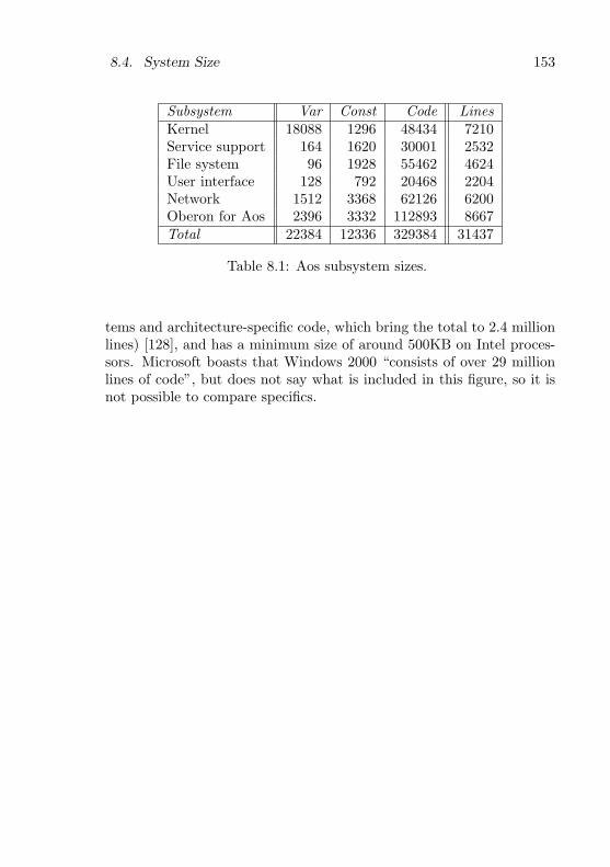
8.4. System Size 153
Subsystem Var Const Code LinesKernel 18088 1296 48434 7210Service support 164 1620 30001 2532File system 96 1928 55462 4624User interface 128 792 20468 2204Network 1512 3368 62126 6200Oberon for Aos 2396 3332 112893 8667Total 22384 12336 329384 31437
Table 8.1: Aos subsystem sizes.
tems and architecture-specific code, which bring the total to 2.4 millionlines) [128], and has a minimum size of around 500KB on Intel proces-sors. Microsoft boasts that Windows 2000 “consists of over 29 millionlines of code”, but does not say what is included in this figure, so it isnot possible to compare specifics.

154 Chapter 8. Evaluation
Chapter 9
Conclusion
This chapter summarizes the work that has been done and outlinespossible future work. Specific contributions of this work are listed atthe end of chapter 1.
9.1 Summary
Our goal was to develop an operating system as lean and transparent asOberon, but more powerful and widely applicable, not only for single-user workstations, but also for servers, embedded control systems andsmall devices. The resulting system, called Aos, is based on the Ac-tive Oberon language which unifies objects and processes in the activeobject concept. The kernel of the system consists of a native runtimeenvironment for Active Oberon.
The Active Oberon language is an extension of the Oberon languagethat allows the representation of concurrent processes as active objects,which are objects with intrinsic concurrent activity. For synchronizingprocesses, the unusual await primitive is used which allows the program-mer to directly specify an arbitrary boolean precondition for continuedexecution of a process. Our contribution to the language developmentis a small, efficient and reliable multiprocessor runtime system runningnatively on modern machines.
The Aos operating system is a modular, extensible system in thestyle of Oberon, with modules arranged in three conceptual layers: theactive object runtime system (kernel), shared system services, and ap-
155
156 Chapter 9. Conclusion
plications. Except for the kernel, all modules are dynamically loadable,which allows flexible configuration and extension of the system at run-time. System service modules and their clients are decoupled with asimple plugin module technique, which facilitates interchangeable sys-tem services based on standard interfaces to increase flexibility. A moregeneral implementation of the Oberon command concept is used to in-stantiate plugin modules and the objects under their control.
The primary purpose of the Aos kernel is to be a complete run-time environment for the Active Oberon language that also allows theprogramming of system-level services, e.g., device drivers. The ker-nel is tuned for this language, but has also been used to support theJava language. The object model supported by the kernel includes typeextension (single-inheritance subclassing), type-bound procedures (vir-tual methods), exclusive type-bound procedures (synchronized meth-ods), object-bound processes and general condition synchronization.
The first version of the Aos kernel was implemented for the IntelIA-32 multiprocessor system architecture, which has a typical small-scale (2–8 processor) symmetric multiprocessing architecture. The ker-nel is composed of several relatively small modules, each with a distinc-tive purpose and simple interface, which contributes to the transparencyof the system. The areas covered by the various modules are (bottom-up): boot loader and hardware environment interface, fine-grained locksfor kernel data structures, serial console output for debugging, virtualaddress space management, object storage management (heap and gar-bage collection), low-level interrupt handling, modules and types, activeobjects, multiple processors and portable kernel interface.
The middle layer of the system contains the shared operating sys-tem services (e.g., the file and communication subsystems) and theirdevice drivers. Service modules typically export an abstract object-based interface, which is then implemented in a plugin module that isnot directly imported by the client. This design helps to reduce thesize of the system. The file subsystem defines a system-wide file namespace, with names consisting of a file system specifier and a local filename. The specifier is a prefix used to locate a specific file system ob-ject, which then interprets the local file name part. This allows thename space to be extended at runtime with different kinds of file sys-tem implementations, e.g., the Aos disk file system that has a flat namespace and the FAT file system that has a hierarchical name space. Disk

9.1. Summary 157
devices are abstracted with a simple, but general, interface. The com-munication subsystem is responsible for communication with externalmachines. It defines and implements interfaces for the TCP/IP inter-net protocols based on abstract link layer device driver objects. Theuser interface subsystem provides basic support for user interfaces inthe form of abstract display and input device objects.
The top layer of the system contains user applications. The mostimportant example application developed by the author is a port of theNative Oberon system to Aos. This allows existing ETH Oberon ap-plications to run on the new system, which also allows the new systemto host its own development tools. The Oberon system can run as afull-screen application or in a window co-existing with other Aos appli-cations. All in all, the implementation of only nine low-level modules ofthe Oberon system had to be modified and one additional driver mod-ule implemented. Another important application is the VNC viewer,which allows remote-controlling of applications running on other oper-ating systems like Unix and Windows. Users of Aos have developedseveral other services and applications (including a parallel compiler,window manager, XML document-based user interface toolkit, Java en-vironment, VNC server, dynamic HTTP server, XML browser, etc.),demonstrating the capabilities of the system.
The flexible modular design of the system makes it suitable for manydifferent application areas and hardware environments, inviting compar-ison with a wide range of systems. The main advantage compared withlarge systems is its transparency, which promises to be an advantagewhen building reliable, secure, and efficient custom applications.
Specific characteristics of the Aos and Linux kernels were comparedusing microbenchmarks. In measurements of basic system call overheadand process creation overhead, Aos is 30 times and 5 times faster, re-spectively. These results show the reduced overhead of the extensiblesystem approach. In measurements of scheduling and locking overhead,it compares favourably with the highly-optimized Linux threads imple-mentation.
Users of the system have demonstrated its portability and flexibilityin two projects. In the first, the system was ported to a different proces-sor and system architecture in four months, including the developmentof a new compiler backend and device drivers. This is a significant devel-opment, because the relevant processor is used in many mobile devices,

158 Chapter 9. Conclusion
a possible application area for Aos. The second project demonstratedthe flexibility of the runtime system through the development of a Javaenvironment based on the kernel. This allows Java and Active Oberonprograms to interoperate by sharing data and procedures.
9.2 Future Work
The aim of any operating system is to be a platform for further work.The various applications and extensions developed by users of Aos havedemonstrated its applicability as a platform, but of course there is al-ways room for improvement.
Conceptual improvements. An open question is how the ActiveOberon language could be improved. In a parallel-running project [26],the type extension concept has been replaced with a definition concept,which enables object orientation based on interfaces instead of subclass-ing. A possible project is the reimplementation of the system using thenew dialect, and a comparison of the size, complexity and performanceof the two implementations.
A concept that was considered during the design of the system, butnot realized in the end, is hierarchical namespaces for modules. It is stillnot conclusive whether a namespace facility is really needed, since therelatively small scale of the system allows simpler solutions. The solu-tion taken was to name the modules of different subsystems or authorswith short unique prefixes, thereby avoiding module name conflicts.
The cooperative environment assumption (cf. 3.1) was made con-sciously to simplify the system design and implementation. The strongtyping and range checking built into the language avoids most problemscaused by erroneous programs. However, if programs that use low-levelfacilities of the language or system have errors, they can cause the sys-tem to become unstable, e.g., due to memory corruption. One way toavoid this is to avoid using these low-level features. Conformance is easyto check by checking the import list of the modules concerned. Anothersolution might be to add a derivative of the domain concept of theVamos system [84], allowing resources to be allocated on a domain-by-domain basis, and sections of the shared address space to be assigned todifferent programs, thereby containing faults to specific domains. Butinstead of complicating the system in this way, one might investigate

9.2. Future Work 159
where and why low-level features are used and replace them with safealternatives, eventually removing all such unsafe features from the lan-guage.
Implementation improvements. The implementation of some por-tions of the system could probably be improved.
A minor point is that the size of the runtime system implementationcan be reduced by removing some tracing and testing code. This wouldhave the side effect of moving the Out module to a higher level of themodule hierarchy, possibly to the system services layer, which would beconceptually cleaner.
Although the microbenchmarks of object locking have shown thatits performance is comparable to that of Linux threads, it can probablybe improved somewhat. A first step could be to simplify the implemen-tation of locks even further, especially the interaction with fine-grainedlocks. There are also opportunities for tuning, e.g., inlining the mostcommon locking operations, but it is questionable if this should be done:it would couple the runtime system and the compiler more closely, whichwould reduce flexibility.
The garbage collection algorithm (cf. 5.6) could be improved. Themain problem is that it is a stop-and-collect algorithm that can not runconcurrently with mutator processes. Although it is adequate for inter-active and server use, for realtime use the delays in the order of tens ofmilliseconds may be too intrusive. Several possible improvements couldbe investigated [15, 50, 55]. The virtual memory manager could be uti-lized to perform a mostly-parallel collection, where the marking processruns concurrently with the mutator. Pseudo-incremental garbage col-lection could be used so that when the system is idle, a non-intrusiverestartable garbage collection is initiated. The pointer rotation algo-rithm could be made non-intrusive (which probably only requires anadditional tag field per heap block), so that it can run concurrentlywith mutator processes. Sweeping could be delayed until allocationtime (lazy sweeping) to amortize sweep time and reduce the pause timeof the collector. The cache performance of the algorithm might beimproved by rearranging the heap structures. By using slightly morestorage (e.g., one word extra per heap block) and not trying to saveevery bit, the algorithms could be simplified more and perhaps speededup in the process.

160 Chapter 9. Conclusion
Porting to other environments. A big strength of a small systemis the ease with which it can be ported to new architectures and envi-ronments. A further advantage is that the type-safe language provides aclean abstraction for application programs and increases their portabil-ity also. Therefore a new port of the system can often immediately beused to run many existing applications without modification. This wasdemonstrated by the Shark port, which supported most existing appli-cations once the basic system was finished. Ports to other ARM-baseddevices are under way, specifically a handheld device and an experimen-tal wearable device.
Extended system services. The services provided by the systemcould be extended.
More standard network protocols and file systems could be imple-mented, as well as drivers for more devices. However, the amount ofwork to be done should not be underestimated. Standards are often de-veloped by large corporations that have an entrenched interest in com-plexity, in order to frustrate competition [86]. The decision to imple-ment Aos first for industry-standard hardware had the advantage thatit could run on powerful and inexpensive machines, but also brought theburden of a wide variety of incompatible hardware components requir-ing custom drivers. For further development it would be advantageousto focus on niche applications where a small system has advantages,e.g., custom-built devices and embedded systems with a stable hard-ware composition.
The Java language environment could be developed further andother similar language environments implemented, but the same caveatsas above hold for these environments.
Applications. Regardless of possible improvements, the system couldbe used in more applications, either for their own sake, or to furtherevaluate its strengths and weaknesses. A fruitful area might be thedevelopment of internet servers and network applications, perhaps inan embedded or mobile environment with small devices.
Appendix A
Module Sizes
Section 8.4 gives an overview of the sizes of various Aos subsystems.This appendix presents the module sizes in more detail.
The following tables show the sizes of the various modules that makeup the Aos kernel and system. In each table, the first column specifiesthe module name. The middle three columns specify the size in bytes ofthe global variables, global constants (including strings), and the IntelIA-32 object code, respectively. The last column specifies the numberof lines of (Active) Oberon source. The modules have all been compiledwith the parallel Active Oberon compiler and include some debuggingand testing code. The modules of the Aos kernel and system are prefixedwith ‘Aos’ in the implementation, to prevent name clashes with existingNative Oberon modules.
Table A.1 shows the modules of the active object runtime kernel.These are defined as the minimum set of modules that can be takentogether as a unit to support Active Oberon programs running on abare IA-32 machine.
Table A.2 shows the modules that provide support for system ser-vices modules. They are not essential for the execution of Active Oberonprograms and are therefore not considered part of the runtime systemkernel.
Tables A.3 through A.5 show independent modules of the systemservices layer and table A.6 shows the base modules of Oberon for Aos.
161

162 Appendix A. Module Sizes
Module Var Const Code LinesAosBoot 2180 40 3462 808AosLocks 4268 16 2227 428AosOut 2048 96 3484 413AosMemory 2916 24 6344 962AosHeap 4236 424 9661 1127AosInterrupts 1736 44 2930 609AosModules 100 148 4698 503AosActive 376 120 8900 1346AosProcessors 220 280 5057 717AosKernel 8 104 1671 297Total 18088 1296 48434 7210
Table A.1: Runtime kernel module sizes.
Module Var Const Code LinesAosPlugins 4 84 1999 176AosCommands 4 148 2507 170AosIO 60 92 7333 788AosTrap 92 1004 8071 628AosLoader 4 292 10091 770Total 164 1620 30001 2532
Table A.2: Service support module sizes.
Module Var Const Code LinesAosDisks 4 80 3455 310AosATADisks 28 848 14166 1329AosCaches 0 76 2457 220AosFS 12 148 10058 1120AosDiskVolumes 48 332 5266 337AosRAMVolumes 4 56 1152 103AosDiskFS 0 388 18908 1205Total 96 1928 55462 4624
Table A.3: File system module sizes.
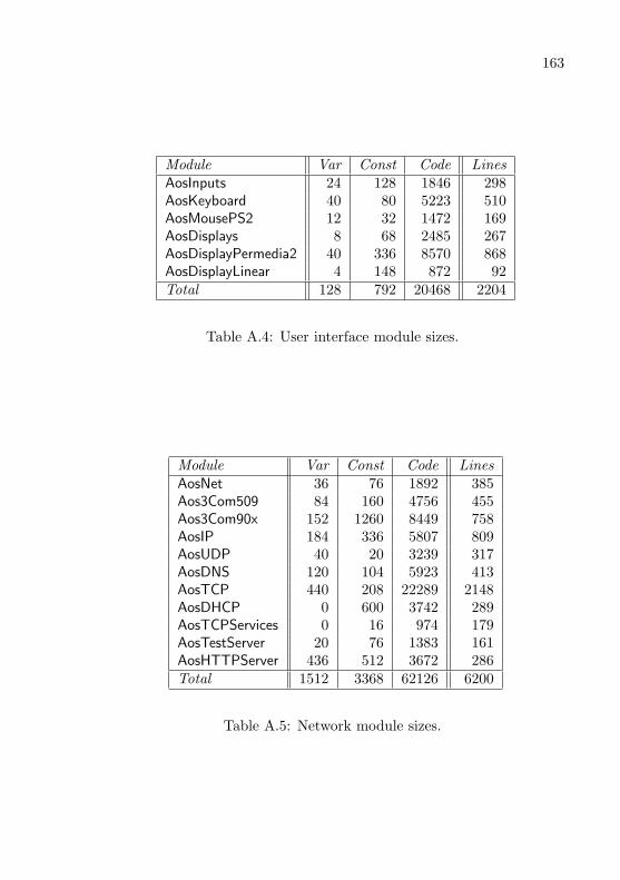
163
Module Var Const Code LinesAosInputs 24 128 1846 298AosKeyboard 40 80 5223 510AosMousePS2 12 32 1472 169AosDisplays 8 68 2485 267AosDisplayPermedia2 40 336 8570 868AosDisplayLinear 4 148 872 92Total 128 792 20468 2204
Table A.4: User interface module sizes.
Module Var Const Code LinesAosNet 36 76 1892 385Aos3Com509 84 160 4756 455Aos3Com90x 152 1260 8449 758AosIP 184 336 5807 809AosUDP 40 20 3239 317AosDNS 120 104 5923 413AosTCP 440 208 22289 2148AosDHCP 0 600 3742 289AosTCPServices 0 16 974 179AosTestServer 20 76 1383 161AosHTTPServer 436 512 3672 286Total 1512 3368 62126 6200
Table A.5: Network module sizes.
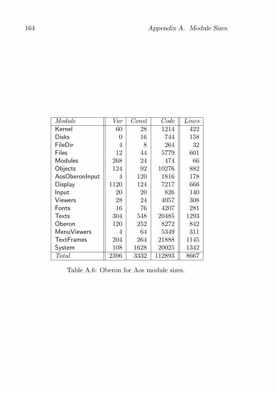
164 Appendix A. Module Sizes
Module Var Const Code LinesKernel 60 28 1214 422Disks 0 16 744 158FileDir 4 8 264 32Files 12 44 5779 601Modules 268 24 474 66Objects 124 92 10276 882AosOberonInput 4 120 1816 178Display 1120 124 7217 666Input 20 20 826 140Viewers 28 24 4057 308Fonts 16 76 4207 281Texts 304 548 20485 1293Oberon 120 252 8272 842MenuViewers 4 64 5349 311TextFrames 204 264 21888 1145System 108 1628 20025 1342Total 2396 3332 112893 8667
Table A.6: Oberon for Aos module sizes.

Appendix B
Technical Notes
This appendix describes the layout of heap blocks in detail. It is in-tended for reference when reading the Oberon source of the Heap module(cf. 5.6).
Object Storage Layout
Figures B.1 through B.6 show the layout of heap blocks. Every heapblock has a tag word in front of it pointing to a type descriptor for theblock. The layout is based on Native Oberon, except for the protectedrecord block (figure B.6), which is unique to Aos. The type descriptorswere slightly modified to allow pointer offsets to be negative. The NativeOberon structures are based on those of other ETH Oberon systems [27].
All heap blocks start with a tag, which is a pointer to a separate typedescriptor block or a meta-type descriptor contained in the heap blockitself. Bit 0 of the tag — the mark bit — is used during the mark phaseof the collector to mark a block that has been reached by the traversal.It is cleared during the sweep phase, so that type tests can be performedwithout having to mask the low bits. Bit 1 — the array bit — is set onan ArrBlk and cleared on all other blocks. With the low two bits maskedoff, the tag value points to the size of the block, which is stored in thetype descriptor or meta-type descriptor (the masked bits are indicatedwith an ‘M’ in the figures). The field offsets of pointer values in the heapblock are stored directly following the size value (see figure B.5), and areterminated by a sentinel that also encodes the number of pointer offsetvalues. During the mark phase the tag (excluding the low two bits) is
165
166 Appendix B. Technical Notes
modified to step through the pointer offset table and thereby store therecursion state of the traversal [85]. When the garbage collector is notrunning, Bit 2 of the tag is always cleared, and Bit 3 is set if the blockhas a real type descriptor, and cleared if it has a meta-type descriptor.
The alignment of heap block fields are indicated on the right-handside of the diagrams. The first data field of a heap block is always alignedso that any basic data type can be placed at that address (addressdivisible by 8). In some cases the garbage collector uses the alignmentrestrictions to recognize what kind of block a pointer is pointing to, byexamining the low bits of the pointer value. These bits are indicated inthe diagrams, with ‘X’ characters indicating don’t-care bits.
The SysBlk, TypeDesc and ProtRecBlk have a meta-type descriptorincluded at the start of the block. This serves only to describe the size ofthe block itself, and includes an empty pointer offset list. It is possiblethat the conservative marking algorithm used for process stacks findsa phantom pointer to the type descriptor, and care has to be taken tohandle these cases in the garbage collector. Possible phantom pointersare indicated with dashed boxes in the figures.
In Native Oberon, a negative sentinel value is used to encode thenumber of pointer offsets in a type descriptor and meta-type descriptor.In Aos, this is not possible as a ProtRecBlk also has legitimate negativepointer offsets in the object header. Instead, a small negative constant(MPO), which is less than the smallest negative pointer offset, is used assentinel. When the garbage collector finds a pointer offset less than thisvalue, it has reached the end of the pointer offset list, and can retrievethe number of pointer offsets from the value found by subtracting MPO.

167
−4tag X100Mq�6
TypeDesc
0
record fields
[padding]
pointer 00000 q - 6
?
recSize
adr = 28(mod 32)
adr = 0(mod 32)
adr = 28(mod 32)
Figure B.1: A RecBlk is used for a record.
−4tag 0000M
0size
4MPO− 4
8
padding
20indirect 00000q�
��� qq -
pointer 11000 q -
pointer 00000
adr = 28(mod 32)
adr = 0(mod 32)
adr = 8(mod 16)24
data
[padding]
6
?
size
adr = 28(mod 32)
Figure B.2: A SysBlk is normally allocated with SYSTEM.NEW.

168 Appendix B. Technical Notes
−4tag X101M
0lastElem
4currElem
8firstElem
12lend−1 = n
.
..len0 = m
4(3 + d)[padding]
4(3 + d + (d − 1) mod 2)
elem0,...,0
elem0,...,1
..
.
elemm−1,...,n−1
[padding]
adr = 0(mod 8)
adr = 28(mod 32)
q�6Element TypeDesc
6
?recSize
00000pointer q - q �
��
q �
��
adr = 28(mod 32)
adr = 0(mod 32)
Figure B.3: An ArrBlk is used for an array when the elements containpointers.

169
−4tag 0000M
0size
4MPO− 4
8
padding
20indirect 00000q�
��� qq -
pointer 11000 q -
pointer 00000
adr = 28(mod 32)
adr = 0(mod 32)
adr = 8(mod 16)
12lend−1 = n
.
..len0 = m
4(3 + d)[padding]
4(3 + d + (d − 1) mod 2)
elem0,...,0
elem0,...,1
.
..
elemm−1,...,n−1
[padding]
adr = 0(mod 8)
adr = 28(mod 32)
24/0
padding
6
?
size
Figure B.4: A SysBlk is used for an array when the elements do notcontain pointers.
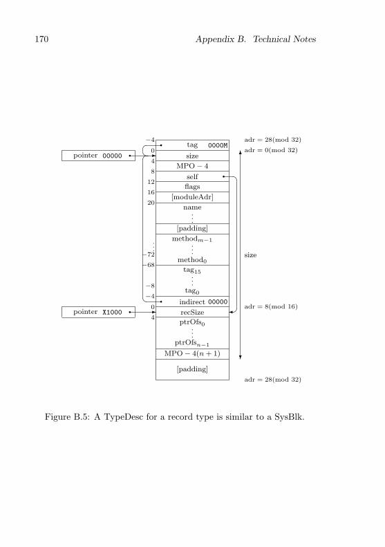
170 Appendix B. Technical Notes
−4tag 0000M
0size
4MPO− 4
8self
12flags
16[moduleAdr]
20name
.
..[padding]
.
.
.
methodm−1...
method0−72
−68tag15
..
.−8tag0−4
indirect 000000
recSize4
ptrOfs0...
ptrOfsn−1
MPO− 4(n + 1)
[padding]
pointer X1000 q -
pointer 00000 q - 6
?
size
q �
��q�
��� q adr = 28(mod 32)
adr = 0(mod 32)
adr = 8(mod 16)
adr = 28(mod 32)
Figure B.5: A TypeDesc for a record type is similar to a SysBlk.
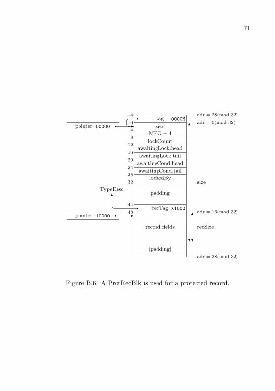
171
−4tag 0000M
0size
4MPO− 4
8lockCount
12awaitingLock.head
16awaitingLock.tail
20awaitingCond.head
24awaitingCond.tail
28lockedBy
32
padding
44recTag X1000q�6
TypeDesc
48
record fields
[padding]
pointer 10000 q -
pointer 00000 q -q�� 6
?
size
6
?
recSize
adr = 28(mod 32)
adr = 0(mod 32)
adr = 16(mod 32)
adr = 28(mod 32)
Figure B.6: A ProtRecBlk is used for a protected record.

172 Appendix B. Technical Notes

Appendix C
Alternative Interrupt Handling
Model
Section 4.3.3 describes a high-level interrupt handling model that wasimplemented in the kernel. Here an alternative model is presented. Thismodel was not implemented, due to its complexity in comparison to theimplemented model.
Await-Interrupt Model
It is appropriate to view a device driver as a cyclic process that awaitsand reacts to interrupts [129]. The handler process communicates withits client processes using the normal interprocess communication facili-ties.
The await-interrupt model for interrupt handling uses active objects,augmented with the await-interrupt statement, which suspends the cur-rent process until a specified interrupt occurs.
Figure C.1 is an example of an await-interrupt model device driverfor a device periodically producing unsolicited data. The device has twostates: uninitialized and initialized, and generates an interrupt when ithas been initialized. After initialization, the device can be programmedto generate an interrupt when unsolicited data becomes available. Thedriver is an active object, with a body for handling interrupts, andmethods for its clients, who communicate with the interrupt handlervia exclusive blocks and await statements (cf. 2.2.2).
173

174 Appendix C. Alternative Interrupt Handling Model
TYPE Driver = OBJECTVAR ”driver state”(* shared by client and driver processes *)
PROCEDURE Read(...); (* client process calls this to read data *)BEGIN {EXCLUSIVE} (* mutually exclusive with driver process *)
”return state information”END Read;
BEGIN {ACTIVE} (* this is the life-cycle of the driver process *)”initialize device””await-interrupt”(* wait for device to respond *)LOOP
”set up device to interrupt when data available””await-interrupt”(* wait for device to generate interrupt *)BEGIN {EXCLUSIVE} (* mutually exclusive with client *)
”get data from device and modify driver state”END
ENDEND Driver;
Figure C.1: Active Oberon pseudo-code of a device driver using theawait-interrupt model.
175
The main advantage of the await-interrupt model is that the devicedriver can be structured to directly reflect the state machine model ofthe device, without resorting to an event-driven programming style.
Non-Sharable Await-Interrupt Algorithm
Under the assumption that at most one process handles an interrupt(i.e., interrupts are not sharable between processes), the await-interruptstatement of the await-interrupt model can be implemented as a call toa runtime procedure that does the following:
1. The running process (the interrupt-handling process) is attachedto the specified interrupt. This means that an entry is made inthe interrupt vector table to associate the handler process withthe interrupt.
2. The interrupt is unmasked by programming the interrupt con-troller.
3. The running process is suspended.
4. The scheduler is invoked to select another process to run, anda context switch is made to continue it from where it was lastsuspended.
When the specified interrupt occurs, the runtime system does thefollowing:
1. The interrupt is masked. This is required to give the interrupthandler process time to remove the source of the interrupt signal.Otherwise, the interrupt would be signalled continually and willlock up the processor.
2. The suspended process is detached from the interrupt and enabled.
3. The scheduler is invoked, and if the newly enabled process has asufficiently high priority, a context switch is made to it immedi-ately. Otherwise, the interrupted process continues to run until itis suspended, or its time slice expires.
Even though it requires the masking of interrupts, this algorithmcan also be applied to handle nonmaskable interrupts. A nonmaskable
176 Appendix C. Alternative Interrupt Handling Model
interrupt is similar to a normal interrupt, except that it has a very highpriority, and can interrupt the processor even when it has disabled otherinterrupts. Despite the name, a nonmaskable interrupt can usually bemasked by the interrupt controller (but not directly by the processor).
Sharable Await-interrupt Algorithm
Here the algorithm is generalized for the case where several processescan wait on the same interrupt (i.e., the interrupt is shared betweendifferent devices and their driver objects). We consider disjunctive setsof processes: each interrupt number has a waiting set and a processingset, and there is a global satisfied set.
• Initially all processes are in the satisfied set, meaning that theyare not awaiting any interrupts.
• When a process in the satisfied set executes the AwaitInterrupt(n)call, it moves to the waiting set for interrupt n and is suspendeduntil interrupt n next occurs.
• When interrupt n occurs, all processes in its waiting set are en-abled and moved to its processing set. Then the scheduler is in-voked, similar to the case described in the non-sharing algorithm.The handling processes can be scheduled to run in parallel on oneor more processors.
• When a process in the processing set of interrupt n executes Await-Interrupt(m), it is moved to waiting set m, and suspended untilinterrupt m next occurs. In the common case, m is equal to n.
• When a process in the processing set of interrupt n terminates, itis moved to the satisfied set.
The reason for distinguishing the sets of processes is that the rulefor masking interrupts can be stated as: Interrupt n is unmasked if, andonly if, its waiting set is non-empty and its processing set is empty. Inother words, an interrupt is unmasked if at least one process is waitingfor it, unless some processes are still handling a previous occurrence. Ifa process enters the waiting set while the processing set is non-empty,it has no effect on the masking of the interrupt.
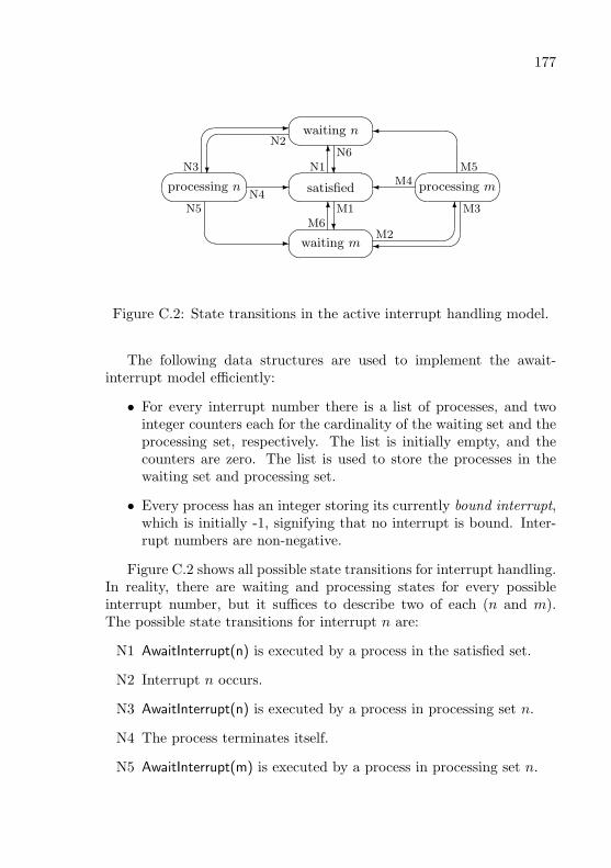
177
�� � waiting n
6N1 ?
N6
� -
?
�N2
N3�� � processing n -N4
�� � satisfied � M4
��
M5�� � processing m
?M16
M6 �
6 M2
M3�� � waiting m� -
N5
Figure C.2: State transitions in the active interrupt handling model.
The following data structures are used to implement the await-interrupt model efficiently:
• For every interrupt number there is a list of processes, and twointeger counters each for the cardinality of the waiting set and theprocessing set, respectively. The list is initially empty, and thecounters are zero. The list is used to store the processes in thewaiting set and processing set.
• Every process has an integer storing its currently bound interrupt,which is initially -1, signifying that no interrupt is bound. Inter-rupt numbers are non-negative.
Figure C.2 shows all possible state transitions for interrupt handling.In reality, there are waiting and processing states for every possibleinterrupt number, but it suffices to describe two of each (n and m).The possible state transitions for interrupt n are:
N1 AwaitInterrupt(n) is executed by a process in the satisfied set.
N2 Interrupt n occurs.
N3 AwaitInterrupt(n) is executed by a process in processing set n.
N4 The process terminates itself.
N5 AwaitInterrupt(m) is executed by a process in processing set n.
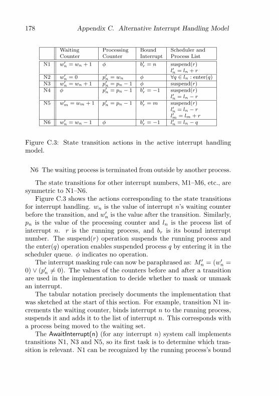
178 Appendix C. Alternative Interrupt Handling Model
Waiting Processing Bound Scheduler andCounter Counter Interrupt Process List
N1 w′n = wn + 1 φ b′r = n suspend(r)
l′n = ln + rN2 w′
n = 0 p′n = wn φ ∀q ∈ ln : enter(q)N3 w′
n = wn + 1 p′n = pn − 1 φ suspend(r)N4 φ p′n = pn − 1 b′r = −1 suspend(r)
l′n = ln − rN5 w′
m = wm + 1 p′n = pn − 1 b′r = m suspend(r)l′n = ln − rl′m = lm + r
N6 w′n = wn − 1 φ b′r = −1 l′n = ln − q
Figure C.3: State transition actions in the active interrupt handlingmodel.
N6 The waiting process is terminated from outside by another process.
The state transitions for other interrupt numbers, M1–M6, etc., aresymmetric to N1–N6.
Figure C.3 shows the actions corresponding to the state transitionsfor interrupt handling. wn is the value of interrupt n’s waiting counterbefore the transition, and w′
n is the value after the transition. Similarly,pn is the value of the processing counter and ln is the process list ofinterrupt n. r is the running process, and br is its bound interruptnumber. The suspend(r) operation suspends the running process andthe enter(q) operation enables suspended process q by entering it in thescheduler queue. φ indicates no operation.
The interrupt masking rule can now be paraphrased as: M ′n = (w′
n =0) ∨ (p′n 6= 0). The values of the counters before and after a transitionare used in the implementation to decide whether to mask or unmaskan interrupt.
The tabular notation precisely documents the implementation thatwas sketched at the start of this section. For example, transition N1 in-crements the waiting counter, binds interrupt n to the running process,suspends it and adds it to the list of interrupt n. This corresponds witha process being moved to the waiting set.
The AwaitInterrupt(n) (for any interrupt n) system call implementstransitions N1, N3 and N5, so its first task is to determine which tran-sition is relevant. N1 can be recognized by the running process’s bound
179
interrupt being −1. It is easy to see from figures C.2 and C.3 that thischaracterizes the satisfied state. N3 can be recognized by the boundinterrupt being equal to the parameter n, and N5 is the case where thebound interrupt is not equal to the parameter n.
Transitions N2 and N4 are implemented straightforwardly by theinterrupt handler procedure for interrupt n, and the process terminationsystem call, respectively.
Transition N6 is required when cleaning up a device driver object. Aspecial TerminateInterrupt system call can be provided for this purpose.

180 Appendix C. Alternative Interrupt Handling Model
List of Figures
2.1 Objects and processes: two viewpoints. . . . . . . . . . . 82.2 Example population of communicating objects. . . . . . 102.3 A generic bounded buffer in Active Oberon. . . . . . . . 122.4 An active object that awaits and reacts to messages on a
network connection. . . . . . . . . . . . . . . . . . . . . 152.5 Extending a bounded buffer to form an active producer
object. . . . . . . . . . . . . . . . . . . . . . . . . . . . . 162.6 A test module for the bounded buffer of figure 2.3. . . . 17
3.1 Overview of the Aos system structure. . . . . . . . . . . 223.2 Plugin object registry example: disk drivers. . . . . . . . 26
4.1 Runtime system location (traditional left, Aos right). . 324.2 Active Oberon pseudo-code of a device driver. . . . . . . 47
5.1 Intel SMP multiprocessor architecture (simplified). . . 505.2 Aos runtime system module structure. . . . . . . . . . 525.3 Typical IA-32 system physical memory layout. . . . . . 605.4 Address space organization (32MB RAM shown). . . . 615.5 Address space organization (4GB RAM shown). . . . . 635.6 All process states and state transitions. . . . . . . . . . 755.7 Overview of the process data structures. . . . . . . . . 78
6.1 File subsystem structure. . . . . . . . . . . . . . . . . . 1006.2 Communication subsystem structure. . . . . . . . . . . 1076.3 TCP object call graph. . . . . . . . . . . . . . . . . . . 1116.4 User interface subsystem structure. . . . . . . . . . . . 119
181

182 List of Figures
7.1 Oberon for Aos user interface modules. . . . . . . . . . 1267.2 VNC example [100]. . . . . . . . . . . . . . . . . . . . . 129
8.1 Aos active object and Linux thread creation time. . . . 1468.2 Aos active object and Linux thread scheduling time. . . 1478.3 Aos exclusive region and Linux mutex lock time (inde-
pendent critical sections). . . . . . . . . . . . . . . . . . 1498.4 Aos exclusive region and Linux mutex lock time (with
heavy contention). . . . . . . . . . . . . . . . . . . . . . 150
B.1 A RecBlk is used for a record. . . . . . . . . . . . . . . 167B.2 A SysBlk is normally allocated with SYSTEM.NEW. . . 167B.3 An ArrBlk is used for an array when the elements contain
pointers. . . . . . . . . . . . . . . . . . . . . . . . . . . 168B.4 A SysBlk is used for an array when the elements do not
contain pointers. . . . . . . . . . . . . . . . . . . . . . . 169B.5 A TypeDesc for a record type is similar to a SysBlk. . 170B.6 A ProtRecBlk is used for a protected record. . . . . . . 171
C.1 Active Oberon pseudo-code of a device driver using theawait-interrupt model. . . . . . . . . . . . . . . . . . . . 174
C.2 State transitions in the active interrupt handling model. 177C.3 State transition actions in the active interrupt handling
model. . . . . . . . . . . . . . . . . . . . . . . . . . . . . 178

List of Tables
5.1 Aos runtime system module responsibilities. . . . . . . 535.2 IA-32 architecture paging options. . . . . . . . . . . . . 59
8.1 Aos subsystem sizes. . . . . . . . . . . . . . . . . . . . 153
A.1 Runtime kernel module sizes. . . . . . . . . . . . . . . . 162A.2 Service support module sizes. . . . . . . . . . . . . . . 162A.3 File system module sizes. . . . . . . . . . . . . . . . . . 162A.4 User interface module sizes. . . . . . . . . . . . . . . . 163A.5 Network module sizes. . . . . . . . . . . . . . . . . . . 163A.6 Oberon for Aos module sizes. . . . . . . . . . . . . . . . 164
183

184 List of Tables

Bibliography
[1] 3Com Inc., 5400 Bayfront Plaza, Santa Clara, CA 95052-8145.Etherlink III Parallel Tasking ISA, EISA, Micro Channel andPCMCIA Adapter Drivers Technical Reference, 1994.
[2] 3Com Inc., 5400 Bayfront Plaza, Santa Clara, CA 95052-8145.3C90x Network Interface Cards Technical Reference, 1997.
[3] 3Dlabs Inc. Permedia 2 Programmer’s Reference Manual, 1997.
[4] Adaptec Inc., 691 South Milpitas Blvd., Milpitas, California95035. SCSI ASIC Solutions: AIC-7890, AIC-7891, AIC-3860Design-in Handbook, 1997.
[5] G. A. Agha. ACTORS: A Model of Concurrent Computation inDistributed Systems. The MIT Press, 1986.
[6] G. A. Agha. Concurrent Object-Oriented Programming. Com-munications of the ACM, 33(9), September 1990.
[7] G. R. Andrews. Foundations of Multithreaded, Parallel, and Dis-tributed Programming. Addison-Wesley, 2000.
[8] ANSI. T13-1153D Working Draft: Information Technology —AT Attachment with Packet Interface Extension (ATA/ATAPI-4), 1997.
[9] A. Baker and J. Lozano. Geratetreiber unter Windows 2000.Markt+Technik Verlag, 2001. Translation of The Windows 2000Device Driver Book, Prentice Hall PTR, 2001.
[10] G. Banfi. Just Another Way to Run Java Programs. Semesterproject, Department of Computer Science, ETH Zurich, 1997.
185

186 Bibliography
[11] T. Berners-Lee, R. Fielding, and H. Frystyk. Hypertext Trans-fer Protocol — HTTP/1.0. RFC 1945, Network Working Group,1996.
[12] B. N. Bershad, R. P. Draves, and A. Forin. Using Microbench-marks to Evaluate System Performance. In Proceedings of theThird Workshop on Workstation Operating Systems (WWOS-3),April 1992.
[13] H. Boehm. A Garbage Collector for C and C++. http://www.-hpl.hp.com/personal/Hans_Boehm/gc/.
[14] H. Boehm. Space Efficient Conservative Garbage Collection. InProceedings of the ACM SIGPLAN ’93 Conference on Program-ming Language Design and Implementation, 1993. ACM SIG-PLAN Notices, 28(6), June 1993.
[15] H. Boehm, A. J. Demers, and S. Shenker. Mostly Parallel GarbageCollection. ACM SIGPLAN Notices, 26(6), 1991.
[16] J. Boykin and A. Langerman. The Parallelization of Mach/-4.3BSD: Design Philosophy and Performance Analysis. In Dis-tributed and Multiprocessor Systems Workshop. USENIX Associ-ation, 1989.
[17] J. M. Bradshaw (ed.). Software Agents. The MIT Press, 1997.
[18] P. Brinch Hansen. Structured Multiprogramming. Communica-tions of the ACM, 15(7), July 1972. Reprinted in [22].
[19] P. Brinch Hansen. Operating System Principles. Prentice-Hall,1973.
[20] P. Brinch Hansen. Experience with Modular Concurrent Program-ming. IEEE Transactions on Software Engineering, 3(2), March1977. Reprinted in [22].
[21] P. Brinch Hansen. Efficient Parallel Recursion. ACM SIGPLANNotices, 30(12):9–16, December 1995. Reprinted in [22].
[22] P. Brinch Hansen. The Search for Simplicity: Essays in ParallelProgramming. IEEE Computer Society Press, 1996.

Bibliography 187
[23] P. Brinch Hansen. Classic Operating Systems. Springer Verlag,2001.
[24] T. Burri. Sound System fur Oberon System 3 (Native Oberon).Semester project, Department of Computer Science, ETH Zurich,1996.
[25] T. Burri. Development of a concurrent dynamic memory manager.Diploma thesis, Department of Computer Science, ETH Zurich,1997.
[26] Computer Systems Institute, ETH Zurich. Active Oberon for.NET. http://www.oberon.ethz.ch/oberon.net/.
[27] R. Crelier. TDescs on the Heap and Subobjects (DECOberonheap blocks). Unpublished sketch, Computer Systems Institute,ETH Zurich.
[28] O. J. Dahl. Monitors Revisited. In A.W. Roscoe, editor, A Clas-sical Mind — Essays in Honour of C.A.R. Hoare. Prentice-Hall,1994.
[29] E. W. Dijkstra. The Structure of the ‘THE’ MultiprogrammingSystem. Communications of the ACM, 11(5):341–346, May 1968.Reprinted in [23].
[30] A. R. Disteli. Integration aktiver Objekte in Oberon am Beispieleines Serversystems. PhD thesis, Computer Systems Institute,ETH Zurich, 1997.
[31] A. R. Disteli and P. Reali. Combining Oberon with Active Ob-jects. In [72], 1997.
[32] R. Droms. Dynamic Host Configuration Protocol. RFC 2131,Network Working Group, 1997.
[33] M. Dubois and C. Scheurich. Synchronization, Coherence andEvent Ordering in Multiprocessors. IEEE Computer, February1988.
[34] B. Egger. Development of an Aos Operating System for theDNARD Network Computer. Diploma thesis, Department ofComputer Science, ETH Zurich, August 2001.

188 Bibliography
[35] B. Egger. Simple Installation and Windows Interoperability forETH Oberon. Semester project, Department of Computer Science,ETH Zurich, 2001.
[36] R. Fielding, J. Gettys, J. Mogul, H. Frystyk, and T. Berners-Lee.Hypertext Transfer Protocol — HTTP/1.1. RFC 2068, NetworkWorking Group, 1997.
[37] M. Franz. Code-Generation On-the-Fly: A Key for Portable Soft-ware. PhD thesis, Computer Systems Institute, ETH Zurich, 1994.
[38] M. Franz. Oberon — The Overlooked Jewel. In L. Boszormenyi,J. Gutknecht, and G. Pomberger, editors, The School of NiklausWirth. dpunkt.verlag, 2000.
[39] M. Frei. Konzipierung eines Display Systems fur Active Oberon.Semester project, Department of Computer Science, ETH Zurich,1999.
[40] T. Frey. A Modern Graphical User Interface for the Aos System.Unpublished report, Computer Systems Institute, ETH Zurich,January 2002.
[41] T. Frey, H. Hogger, O. Joos, and P. Kramer. Development of anOberon System for the hyperstone E1 CPU. Semester project,Department of Computer Science, ETH Zurich, 1998.
[42] B. Gamsa, O. Krieger, J. Appavoo, and M. Stumm. Tornado:Maximizing Locality and Concurrency in a Shared Memory Mul-tiprocessor Operating System. In Third Symposium on OperatingSystem Design and Implementation (OSDI ’99). USENIX Associ-ation, 1999.
[43] R. Griesemer. On the Linearization of Graphs and Writing Sym-bol Files. Yellow Report 156, Computer Systems Institute, ETHZurich, March 1991. Published with [85].
[44] J. Gutknecht. Oberon, Gadgets and Some Archetypal Aspectsof Persistent Objects. Technical Report 243, Computer SystemsInstitute, ETH Zurich, February 1996.

Bibliography 189
[45] J. Gutknecht. Do the Fish Really Need Remote Control? A Pro-posal for Self-Active Objects in Oberon. In [72], 1997.
[46] H. Hartig, M. Hohmuth, J. Liedtke, S. Schonberg, and J. Wolter.The Performance of µ-Kernel-Based Systems. In Proceedings ofthe Sixteenth ACM Symposium on Operating Systems Principles,October 1997. ACM Operating Systems Review 31(5), December1997.
[47] C.A.R. Hoare. Monitors: An Operating System Structuring Con-cept. Communications of the ACM, 17(10):549–557, October1974.
[48] C.A.R. Hoare. Communicating Sequential Processes. Prentice-Hall, 1985.
[49] F. Hrebabetzky. Closed-Loop Control with Oberon. Software —Concepts and Tools, 18:73–79, 1997.
[50] IECC. The Garbage Collection List. Mailing list. Archive athttp://www.iecc.com/gclist/.
[51] Intel Corp. Pentium Pro Family Developer’s Manual Volume 3:Operating System Writer’s Guide, 1996.
[52] Intel Corp. 82371 FB (PIIX) and 82371SB (PIIX3) PCI ISA IDEXcelerator Data Book, 1997.
[53] Intel Corp. IA-32 Intel Architecture Software Developer’s ManualVolume 3: System Programming Guide, 2001. Order Number245472, http://developer.intel.com/.
[54] Internet Engineering Task Force, Network Working Group. Inter-net Official Protocol Standards, 2001. RFC 3000.
[55] R. Jones and R. Lins. Garbage Collection: Algorithms for Auto-matic Dynamic Memory Management. Wiley, 1996.
[56] J.L. Keedy. On Structuring Operating Systems With Monitors.ACM Operating Systems Review, 13(1), January 1979.
[57] C. Kleiner. Four Dimensional Dreams. Diploma thesis, Depart-ment of Computer Science, ETH Zurich, March 1999.

190 Bibliography
[58] J. Kreienbuhl. VNC Viewer for Oberon. Semester project, De-partment of Computer Science, ETH Zurich, 1999.
[59] F. Kuhn. Accellerated Display Driver and 3D Graphics Library forthe Permedia 2 chip. Semester project, Department of ComputerScience, ETH Zurich, 1999.
[60] S. Lalis and B. A. Sanders. Adding Concurrency to the Obe-ron System. In J. Gutknecht, editor, Lecture Notes in ComputerScience 782: Programming Languages and System Architectures,pages 328–344. Springer Verlag, March 1994.
[61] B. W. Lampson and D. D. Redell. Experience with Processes andMonitors in Mesa. Communications of the ACM, 23(2):105–117,February 1980.
[62] A.M. Lister and P.J. Sayer. Hierarchical Monitors. Software —Practice and Experience, 7:613–623, 1977.
[63] J. Marais. Design and Implementation of a Component Architec-ture for Oberon. PhD thesis, Computer Systems Institute, ETHZurich, 1996.
[64] J. Mauro and R. McDougall. Solaris Internals. Prentice-Hall,2001.
[65] M. K. McKusick, K. Bostic, M. J. Karels, and J. S. Quarterman.The Design and Implementation of the 4.4BSD Operating System.Addison-Wesley, 1996.
[66] B. Meyer. Systematic Concurrent Object-Oriented Programming.Communications of the ACM, 36(9), September 1993.
[67] P. Mockapetris. Domain Names — Concepts and Facilities. RFC1034, Information Sciences Institute, University of Southern Cal-ifornia, 1987.
[68] P. Mockapetris. Domain Names — Implementation and Specifi-cation. RFC 1035, Information Sciences Institute, University ofSouthern California, 1987.

Bibliography 191
[69] D. Mosberger. Memory Consistency Models. Technical ReportTR 93/11, Department of Computer Science, The University ofArizona, 1993.
[70] H. P. Mossenbock, J. Templ, and R. Griesemer. Object Oberon:An Object-Oriented Extension of Oberon. Yellow Report 109,Computer Systems Institute, ETH Zurich, June 1989.
[71] H. P. Mossenbock and N. Wirth. The Programming LanguageOberon-2. Structured Programming, 12(4), 1991.
[72] H. P. Mossenbock (ed.). Lecture Notes in Computer Science1204: Proceedings of the Joint Modular Languages Conference,JMLC’97. Springer Verlag, March 1997.
[73] D. Muller. Development of a 64-bit MIPS Implementation of theOberon System. Diploma thesis, Department of Computer Sci-ence, ETH Zurich, 1997.
[74] P. J. Muller. Native Oberon Operating System. Web site. http://-www.oberon.ethz.ch/native/.
[75] P. J. Muller and P. J. A. de Villiers. Using Oberon to Design a Hi-erarchy of Extensible Device Drivers. In P. Schulthess, editor, Pro-ceedings of the Joint Modular Languages Conference, JMLC’94,Ulm, Germany, September 1994. Universitatsverlag Ulm.
[76] Olivetti Research. Virtual Network Computing. http://www.uk.-research.att.com/vnc/.
[77] E. Oswald. A Generic 2D Graphics API with Object Frameworkand Applications. PhD thesis, Computer Systems Institute, ETHZurich, 2000.
[78] D. L. Parnas. Designing Software for Ease of Extension and Con-traction. IEEE Transactions on Software Engineering, SE-5(2),March 1979.
[79] D. L. Parnas. Why Software Jewels Are Rare. IEEE Computer,29(2), February 1996.
192 Bibliography
[80] D. L. Parnas and D. P. Siewiorek. Use of the Concept of Trans-parency in the Design of Hierarchically Structured Systems. Com-munications of the ACM, 18(7), July 1975.
[81] D.L. Parnas. On the Criteria to be Used in Decomposing Systemsinto Modules. Communications of the ACM, 15(12), December1972.
[82] PCI Special Interest Group. PCI Local Bus Specification, Revision2.2, 1998. http://www.pcisig.com/.
[83] J. K. Peacock. File System Multithreading in System V Release4 MP. In USENIX Summer 1992 Technical Conference, pages19–29. USENIX Association, June 1992.
[84] F. V. Peschel. Vamos — Entwurf und Realisierung eines erweiter-baren Betriebssystems fur Arbeitsplatzrechner. PhD thesis, Com-puter Systems Institute, ETH Zurich, 1989.
[85] C. Pfister (ed.), B. Heeb, and J. Templ. Oberon Technical Notes.Yellow Report 156, Computer Systems Institute, ETH Zurich,March 1991. Published with [43].
[86] R. Pike. Systems Software Research is Irrelevant. Presentation atthe Symposium on Operating Systems Principles (SOSP), Febru-ary 2000. http://www.cs.bell-labs.com/who/rob/utah2000.pdf.
[87] C. Plattner. Universal Serial Bus Unterstutzung fur ETH Oberon.Semester project, Department of Computer Science, ETH Zurich,2000.
[88] D. C. Plummer. An Ethernet Address Resolution Protocol. RFC826, Network Working Group, 1982.
[89] J. Postel. Echo Protocol. RFC 862, Information Sciences Institute,University of Southern California, 1983.
[90] J. Postel (ed.). User Datagram Protocol. RFC 768, InformationSciences Institute, University of Southern California, 1980.
[91] J. Postel (ed.). Internet Control Message Protocol. RFC 792,Information Sciences Institute, University of Southern California,1981.

Bibliography 193
[92] J. Postel (ed.). Internet Protocol. RFC 791, Information SciencesInstitute, University of Southern California, 1981.
[93] J. Postel (ed.). Transmission Control Protocol. RFC 793, In-formation Sciences Institute, University of Southern California,1981.
[94] P. Reali. Jaos. Web site. http://www.oberon.ethz.ch/jaos/.
[95] P. Reali. Structuring a Compiler with Active Objects. In JointModular Languages Conference. Springer Verlag, September 2000.
[96] P. Reali. Language Interoperability. PhD thesis, Computer Sys-tems Institute, ETH Zurich, 2002.
[97] Realtek Semiconductor Corp. Realtek RTL8139(A/B) Program-ming Guide, 1999.
[98] M. Reiser and N. Wirth. Programming in Oberon: Steps beyondPascal and Modula. Addison-Wesley, 1992.
[99] Digital Research. The DIGITAL Network Appliance ReferenceDesign. Web site. http://www.research.compaq.com/SRC/iag/.
[100] T. Richardson, Q. Stafford-Fraser, K. R. Wood, and A. Hopper.Virtual Network Computing. IEEE Internet Computing, 2(1),January/February 1998.
[101] T. Richardson and K. R. Wood. The RFB Protocol. Technicalreport, Olivetti Research Lab, Cambridge, 1998.
[102] R.Laich. Eine Java Virtual Machine fur Aos. Diploma thesis,Department of Computer Science, ETH Zurich, 2001.
[103] M. Russinovich. Win2K Queued Spinlocks. http://www.compu-ware.com/products/driverstudio/resources/% -papers/spinlocks.-htm.
[104] S3 Inc., Santa Clara, CA 95052-8058. Trio64V+ Integrated Graph-ics/Video Accelerator, 1996.
[105] R. W. Scheifler, J. Gettys, D. Converse, and A. Mento. X WindowSystem: Core Libraries and Standards. Butterworth-Heinemann,1996.

194 Bibliography
[106] C. Schimmel. Unix Systems for Modern Architectures. Addison-Wesley, 1994.
[107] H. Schorr and W. Waite. An Efficient Machine-Independent Pro-cedure for Garbage Collection in Various List Structures. Com-munications of the ACM, 10(8), August 1967.
[108] M. L. Scott, T. J. LeBlanc, B. D. Marsh, T. G. Becker, C. Dub-nicki, E. P. Markatos, and N. G. Smithline. Implementation Issuesfor the Psyche Multiprocessor Operating System. Computing Sys-tems, 3(1), Winter 1990.
[109] D. Seal (ed.). ARM Architecture Reference Manual. Addison-Wesley, second edition, 2001.
[110] J. Sedlacek. Project C2: A Survey of an Industrial EmbeddedApplication with PC Native Oberon. In Joint Modular LanguagesConference. Springer Verlag, September 2000.
[111] A. Signer. Development of an Oberon System 3 for the DNARDNetwork Computer. Diploma thesis, Department of ComputerScience, ETH Zurich, 1999.
[112] A. Silberschatz and P. B. Galvin. Operating System Concepts.Addison-Wesley, fifth edition, 1998.
[113] W. Simpson (ed.). The Point-to-Point Protocol (PPP). RFC 1661,Network Working Group, 1994.
[114] D. A. Solomon and M. E. Russinovich. Inside Microsoft Windows2000. Microsoft Press, third edition, 2000.
[115] R. Strobl. Optimizing the Native Oberon NetSystem. Semesterproject, Department of Computer Science, ETH Zurich, 1999.
[116] P. Studi. Ein Client-Server Filesystem fur Aos. Semester project,Department of Computer Science, ETH Zurich, 2001.
[117] J. Supcik. HP-Oberon – The Oberon Implementation for HP 9000Series 700. Yellow Report 212, Computer Systems Institute, ETHZurich, 1994.

Bibliography 195
[118] C. A. Szyperski. Insight ETHOS: On Object-Orientation in Op-erating Systems. PhD thesis, Computer Systems Institute, ETHZurich, 1992.
[119] A. S. Tanenbaum. Modern Operating Systems. Prentice-Hall,1992.
[120] J. Templ. Metaprogramming in Oberon. PhD thesis, ComputerSystems Institute, ETH Zurich, 1994.
[121] C. P. Thacker and L. C. Stewart. Firefly: A Multiprocessor Work-station. In Proceedings of the Second International Conference onArchitectural Support for Programming Languages and OperatingSystems (ASPLOS II), October 1987.
[122] R. C. Unrau, O. Krieger, B. Gamsa, and M. Stumm. HierarchicalClustering: A Structure for Scalable Multiprocessor OperatingSystem Design. The Journal of Supercomputing, 9:105–136, 1995.
[123] USB Org. Universal Serial Bus (USB) Specification Rev. 2.0,2000. http://www.usb.org/.
[124] F. van Gilluwe. The Undocumented PC: A Programmer’s Guide.Addison-Wesley, second edition, 1997.
[125] Video Electronics Standards Association, 2150 North First Street,Suite 440, San Jose, CA 95131-2029. Vesa BIOS Extension (VBE)Core Functions Version 2.0.
[126] C. von Praun and T. Gross. Compiler-based Object Consistency.In Workshop on Caching, Coherency and Consistency (WC3 ’01),June 2001.
[127] S. Walthert. Entwicklung eines Style Layers und Renderers furdie XML-basierte GUI-Shell des Aos Systems. Diploma thesis,Department of Computer Science, ETH Zurich, 2001.
[128] D. A. Wheeler. More Than a Gigabuck: Estimating GNU/Linux’sSize. http://www.dwheeler.com/sloc/.
[129] N. Wirth. Modula: A Language for Modular Multiprogramming.Software — Practice and Experience, 7:3–35, 1977.
196 Bibliography
[130] N. Wirth. The Use of Modula. Software — Practice and Experi-ence, 7:37–65, 1977.
[131] N. Wirth. Programming in Modula-2. Springer Verlag, third,corrected edition, 1985.
[132] N. Wirth. The Programming Language Oberon. Software —Practice and Experience, 18(7):671–690, July 1988.
[133] N. Wirth. A Plea for Lean Software. IEEE Computer, February1995.
[134] N. Wirth and J. Gutknecht. Project Oberon: The Design of anOperating System and Compiler. Addison-Wesley, 1992.
[135] G. R. Wright and W. R. Stevens. TCP/IP Illustrated, volume 2.Addison-Wesley, 1995.
[136] W. Wulf, E. Cohen, W. Corwin, A. Jones, R. Levin, C. Pierson,and F. Pollack. HYDRA: The Kernel of a Multiprocessor Oper-ating System. Communications of the ACM, 17(6), June 1974.
[137] W. A. Wulf, R. Levin, and S. P. Harbison. HYDRA/C.mmp —An Experimental Computer System. McGraw-Hill, 1981.
[138] B. G. Zorn. Comparative Performance Evaluation of Garbage Col-lection Algorithms. PhD thesis, University of California at Berke-ley, December 1989.

Curriculum Vitae
Pieter Johannes Muller
11th July 1968 Born in Nababeep, South Africa. Son of Andriesand Coerie Muller.
1975–1983 High School Nababeep, South Africa.
1984–1986 Paul Roos Gimnasium, Stellenbosch, South Africa.
1987–1989 B.Sc. Mathematical Sciences, Stellenbosch University,South Africa.
1990–1991 B.Sc. Hons. Computer Science, Stellenbosch University,South Africa.
1991–1994 M.Sc. (cum laude) Computer Science, StellenboschUniversity, South Africa.
1991–1995 Research assistant, Instituut vir ToegepasteRekenaarwetenskap, Stellenbosch University, South Africa.
1995–2001 Research and teaching assistant, Computer SystemsInstitute, ETH Zurich.
2002 Research and development engineer, MCT Lab GmbH, Zurich.
197