
Supported Residential Facility (SRF) Support Program West SRF Exercise Group
Upload
duongxuyenCategory
view
220download
2
BNL-100747-2013-CP
The 300 mA SRF ERL
I. Ben-Zvi
Presented at the Workshop to Explore Physics Opportunities with Intense, Polarized Electron Beams Up to 300 MeV
Cambridge, MA March 14-16, 2013
Collider-Accelerator Department Brookhaven National Laboratory
U.S. Department of Energy
DOE Office of Science Notice: This manuscript has been authored by employees of Brookhaven Science Associates, LLC under Contract No. DE-AC02-98CH10886 with the U.S. Department of Energy. The publisher by accepting the manuscript for publication acknowledges that the United States Government retains a non-exclusive, paid-up, irrevocable, world-wide license to publish or reproduce the published form of this manuscript, or allow others to do so, for United States Government purposes. This preprint is intended for publication in a journal or proceedings. Since changes may be made before publication, it may not be cited or reproduced without the author’s permission.

DISCLAIMER
This report was prepared as an account of work sponsored by an agency of the United States Government. Neither the United States Government nor any agency thereof, nor any of their employees, nor any of their contractors, subcontractors, or their employees, makes any warranty, express or implied, or assumes any legal liability or responsibility for the accuracy, completeness, or any third party’s use or the results of such use of any information, apparatus, product, or process disclosed, or represents that its use would not infringe privately owned rights. Reference herein to any specific commercial product, process, or service by trade name, trademark, manufacturer, or otherwise, does not necessarily constitute or imply its endorsement, recommendation, or favoring by the United States Government or any agency thereof or its contractors or subcontractors. The views and opinions of authors expressed herein do not necessarily state or reflect those of the United States Government or any agency thereof.
1
The 300 mA SRF ERL
Introduction
High-average-current accelerators, electron and proton alike, are now in the frontier of accelerator science and technology. These machines are at the intensity frontier of particle physics, such as Project-X for protons and LHeC for electrons and high-luminosity colliders in nuclear physics such as eRHIC. Energy Recovery Linacs (ERL) provide the highest possible current for applications that do not destroy the electron beam, and thus are well suited for electron-hadron colliders, high-power Free-Electron lasers for industrial applications and directed energy defense systems, intense Tera Hertz (THz), generation of Compton X-rays and so on.
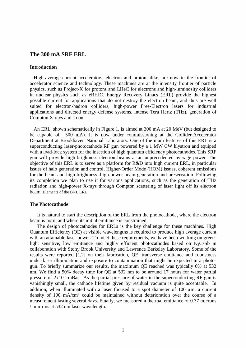
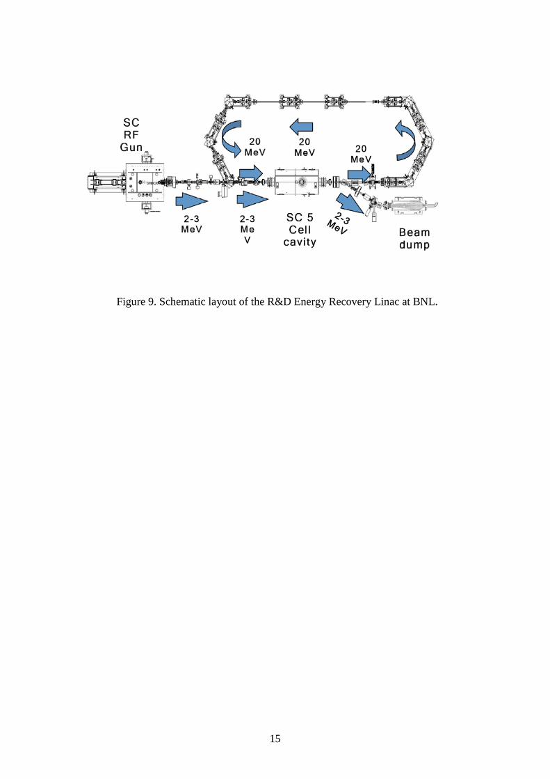
An ERL, shown schematically in Figure 1, is aimed at 300 mA at 20 MeV (but designed to
be capable of 500 mA). It is now under commissioning at the Collider-Accelerator Department at Brookhaven National Laboratory. One of the main features of this ERL is a superconducting laser-photocathode RF gun powered by a 1 MW CW klystron and equiped with a load-lock system for the insertion of high quantum efficiency photocathodes. This SRF gun will provide high-brightness electron beams at an unprecedented average power. The objective of this ERL is to serve as a platform for R&D into high current ERL, in particular issues of halo generation and control, Higher-Order Mode (HOM) issues, coherent emissions for the beam and high-brightness, high-power beam generation and preservation. Following its completion we plan to use it for various applications, such as the generation of THz radiation and high-power X-rays through Compton scattering of laser light off its electron beam. Elements of the BNL ERL
The Photocathode
It is natural to start the description of the ERL from the photocathode, where the electron beam is born, and where its initial emittance is constrained.
The design of photocathodes for ERLs is the key challenge for these machines. High Quantum Efficiency (QE) at visible wavelengths is required to produce high average current with an attainable laser power. To meet these requirements, we have been working on green-light sensitive, low emittance and highly efficient photocathodes based on K2CsSb in collaboration with Stony Brook University and Lawrence Berkeley Laboratory. Some of the results were reported [1,2] on their fabrication, QE, transverse emittance and robustness under laser illumination and exposure to contamination that might be expected in a photo-gun. To briefly summarize our results, the maximum QE reached was typically 6% at 532 nm. We find a 50% decay time for QE at 532 nm to be around 17 hours for water partial pressure of 2x10⁻⁹ mBar. As the partial pressure of water in the superconducting RF gun is vanishingly small, the cathode lifetime given by residual vacuum is quite acceptable. In addition, when illuminated with a laser focused to a spot diameter of 100 µm, a current density of 100 mA/cm2 could be maintained without deterioration over the course of a measurement lasting several days. Finally, we measured a thermal emittance of 0.37 microns / mm-rms at 532 nm laser wavelength.
2
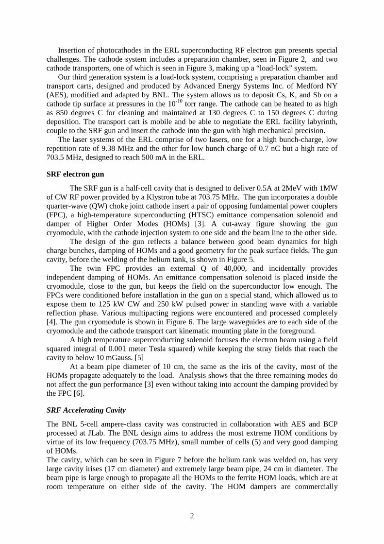
Insertion of photocathodes in the ERL superconducting RF electron gun presents special challenges. The cathode system includes a preparation chamber, seen in Figure 2, and two cathode transporters, one of which is seen in Figure 3, making up a “load-lock” system.
Our third generation system is a load-lock system, comprising a preparation chamber and transport carts, designed and produced by Advanced Energy Systems Inc. of Medford NY (AES), modified and adapted by BNL. The system allows us to deposit Cs, K, and Sb on a cathode tip surface at pressures in the 10-10 torr range. The cathode can be heated to as high as 850 degrees C for cleaning and maintained at 130 degrees C to 150 degrees C during deposition. The transport cart is mobile and be able to negotiate the ERL facility labyrinth, couple to the SRF gun and insert the cathode into the gun with high mechanical precision.
The laser systems of the ERL comprise of two lasers, one for a high bunch-charge, low repetition rate of 9.38 MHz and the other for low bunch charge of 0.7 nC but a high rate of 703.5 MHz, designed to reach 500 mA in the ERL.
SRF electron gun
The SRF gun is a half-cell cavity that is designed to deliver 0.5A at 2MeV with 1MW of CW RF power provided by a Klystron tube at 703.75 MHz. The gun incorporates a double quarter-wave (QW) choke joint cathode insert a pair of opposing fundamental power couplers (FPC), a high-temperature superconducting (HTSC) emittance compensation solenoid and damper of Higher Order Modes (HOMs) [3]. A cut-away figure showing the gun cryomodule, with the cathode injection system to one side and the beam line to the other side.
The design of the gun reflects a balance between good beam dynamics for high charge bunches, damping of HOMs and a good geometry for the peak surface fields. The gun cavity, before the welding of the helium tank, is shown in Figure 5.
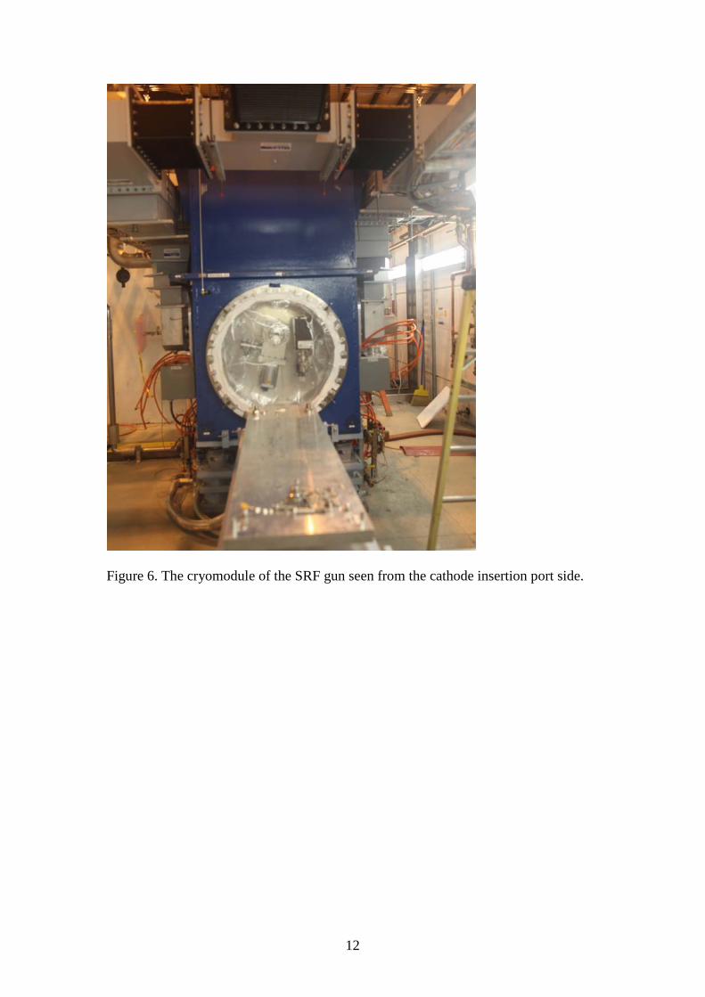
The twin FPC provides an external Q of 40,000, and incidentally provides independent damping of HOMs. An emittance compensation solenoid is placed inside the cryomodule, close to the gun, but keeps the field on the superconductor low enough. The FPCs were conditioned before installation in the gun on a special stand, which allowed us to expose them to 125 kW CW and 250 kW pulsed power in standing wave with a variable reflection phase. Various multipacting regions were encountered and processed completely [4]. The gun cryomodule is shown in Figure 6. The large waveguides are to each side of the cryomodule and the cathode transport cart kinematic mounting plate in the foreground.
A high temperature superconducting solenoid focuses the electron beam using a field squared integral of 0.001 meter Tesla squared) while keeping the stray fields that reach the cavity to below 10 mGauss. [5]
At a beam pipe diameter of 10 cm, the same as the iris of the cavity, most of the HOMs propagate adequately to the load. Analysis shows that the three remaining modes do not affect the gun performance [3] even without taking into account the damping provided by the FPC [6].
SRF Accelerating Cavity
The BNL 5-cell ampere-class cavity was constructed in collaboration with AES and BCP processed at JLab. The BNL design aims to address the most extreme HOM conditions by virtue of its low frequency (703.75 MHz), small number of cells (5) and very good damping of HOMs. The cavity, which can be seen in Figure 7 before the helium tank was welded on, has very large cavity irises (17 cm diameter) and extremely large beam pipe, 24 cm in diameter. The beam pipe is large enough to propagate all the HOMs to the ferrite HOM loads, which are at room temperature on either side of the cavity. The HOM dampers are commercially

3
available, derived from the Cornell 500 MHz storage ring cavity design. As a result of these design features the cavity is a “single mode” cavity, all HOMs are strongly coupled to the HOM damper, and the loss factor is very low [7]. The cell shape also enhances mechanical stability. The power source for the accelerating cavity is a high efficiency (over 50%) IOT Amplifier. The gun cryomodule with part of the ERL beam line can be seen in Figure 8. The cylinder on top of the cryomodule is a helium ballast tank.
The ERL cryogenic system provides 2K superfluid helium cooling to the super-conducting RF gun and the 5-cell RF cavity. The cryogenic system includes a 300W 4.5K coldbox, a wet expander, and a 2K to 4K recovery heat exchanger for each cryomodule to recover refrigeration below 4K. The 2K superfluid bath is produced by pumping using a sub-atmospheric warm compression system. The system includes 45 g/s screw compressor, a 3800 liter liquid helium storage dewar, a 170 m3 warm gas storage tank, and a 40,000 liter liquid nitrogen storage dewar.
Beam optics
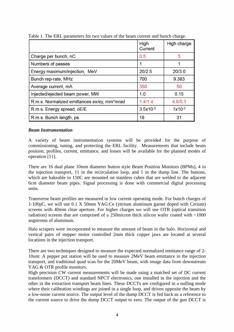
One of the critical parts of the ERL is the merger of the low-energy and high-energy beams. The injection energy is not recovered. Low injection energy requires less RF power and lowers dumped beam energy. A novel emittance preserved merger system is implemented in this ERL. Beam dynamics simulation the R&D ERL injector indicates that for an electron bunch of 0.7 nC, the ERL will have equal normalized emittances in vertical and horizontal planes of 1.4 mm-mrad [8]. Table 1 shows the beam parameters of the ERL as calculated using the PARMELA program for two design beam current and charge. The lattice of the ERL loop is very flexible for the various studies and applications we plan. The adjustable part of the lattice has two arcs and a straight section. Each arc is an achromatic with adjustable longitudinal dispersion value from +1 m to -1 m. Quadrupoles in the dispersion-free straight section provides for matching of the end quadrupoles. One of the two 180 degrees arcs is movable by ±1/8 RF wavelength. This allows the ERL to be also configured as a two-pass recirculating linac with no energy recovery. In this mode the machine should be capable of 1 mA average current at 40 MeV. However, some minor modifications would be required in this case, in particular the addition of another beam dump. More details about R&D ERL optics can be found [9]. The return loop magnets are of traditional design with the following exceptions: a) The bending radius of the 60o dipole magnets is 20 cm, which is rather small. We use 15o edges on both sides of the dipoles to split the very strong focusing evenly between the horizontal and vertical planes (so-called chevron-magnet). b) The requirements on field quality of the loop’s quadrupoles had been determined by the requirement to preserve a very low normalized transverse slice emittance of electron beam (εn~ 1mm-mrad). We used direct tracking of a sample electron beam to verify a high degree of the emittance preservation [10]. c) Each quadrupole is equipped with a dipole trim coil, which can be also used to excite a sextupole component, if required, for emittance preservation of e-beam with a large energy spread. All the ERL magnets are accurately CNC machined and installed on similarly machined bases. Within each base there is no provision for alignment, the CNC machining achieves tolerances better than a survey procedure. We use a commercially available beam dump modified to the ERL special needs. The beam dump design is based on a standard 1 MW klystron beam dump. The beam dump is designed to have the capability for removing 1 MW of unrecovered electron beam power with beam energy of 5 MeV.
4
Table 1. The ERL parameters for two values of the beam current and bunch charge.
Beam Instrumentation
A variety of beam instrumentation systems will be provided for the purpose of commissioning, tuning, and protecting the ERL facility. Measurements that include beam position, profiles, current, emittance, and losses will be available for the planned modes of operation [11].
There are 16 dual plane 10mm diameter button style Beam Position Monitors (BPMs), 4 in the injection transport, 11 in the recirculation loop, and 1 in the dump line. The buttons, which are bakeable to 150C are mounted on stainless cubes that are welded to the adjacent 6cm diameter beam pipes. Signal processing is done with commercial digital processing units.
Transverse beam profiles are measured in low current operating mode. For bunch charges of 1-100pC, we will use 0.1 X 50mm YAG:Ce (yttrium aluminum garnet doped with Cerium) screens with 40mm clear aperture. For higher charges we will use OTR (optical transition radiation) screens that are comprised of a 250micron thick silicon wafer coated with ~1000 angstroms of aluminum.
Halo scrapers were incorporated to measure the amount of beam in the halo. Horizontal and vertical pairs of stepper motor controlled 2mm thick copper jaws are located at several locations in the injection transport. There are two techniques designed to measure the expected normalized emittance range of 2-10um: A pepper pot station will be used to measure 2MeV beam emittance in the injection transport, and traditional quad scan for the 20MeV beam, with image data from downstream YAG & OTR profile monitors. High precision CW current measurements will be made using a matched set of DC current transformers (DCCT) and standard NPCT electronics, one installed in the injection and the other in the extraction transport beam lines. These DCCTs are configured in a nulling mode where their calibration windings are joined in a single loop, and driven opposite the beam by a low-noise current source. The output level of the dump DCCT is fed back as a reference to the current source to drive the dump DCCT output to zero. The output of the gun DCCT is
5
then a differential current measurement [12]. The anticipated sub-microampere resolution may permit using this diagnostic as a second layer of the machine protection system. Bunch-by-bunch & bunch train charge will be measured by an in-flange Integrating Current Transformer (ICT) located in the upstream injection line. The nominal integrating window is 4us, but can be adjusted shorter or longer based on the temporal limits of the electronics. Photomultiplier tube (PMT) based loss detectors are installed at locations where beam loss is most likely. Eight Ion Chamber (IC) loss detectors are employed at select locations in the ERL. These are 113cc glass bottles with BNC & SHV connectors for signal and bias. Ion chamber type loss monitors based on gas filled heliax cable are also employed at the ERL. In addition to amplitude proportional beam loss detection as provided from the PMT, IC, & heliax detectors, event count based detectors are employed. PIN Diode loss detector modules, Bergoz model BLM, installed at eight select locations in ERL. These modules are built around two PIN photodiodes mounted face-to-face making use of coincidence counting to be insensitive to synchrotron radiation photons. With extremely low spurious count rate of < 1 in 10 sec, up to 10 MHz counting, dynamic range of 108, and 100nS recovery time, these detectors are of the lowest costs and highest dynamic ranges available. The TTL data output of each detector is counted by a scalar VME module. Thermal imagers will be used at several locations to measure beam pipe temperature gradients to ensure beam losses not seen by other loss detectors are monitored. The camera offers image transfer and control via Ethernet, and configurable location specific temperature thresholds on the image can be programmed and used to provide a machine protection alarm or interlock signal from a digital output port on the camera assembly.
Summary
We provided a brief description of the design of the various subsystems of a 300 mA, 20 MeV R&D ERL. A detailed description of the ERL can be found in the literature [13]. The ERL currently is in commissioning at Brookhaven National Laboratory. The R&D program will address the high-current, low-emittance properties of the system, like coherent emissions, beam halo evolution and mitigation and emittance preservation. We plan to increase the current gradually from sub-mA to ampere-class in stages, to be followed by applications such as the generation of very high repetition rate terahertz radiation.
References
1. T. Vecchione, I. Ben-Zvi, D. H. Dowell, J. Feng, T. Rao, J. Smedley, W. Wan, and H. A. Padmore, A Low Emittance and High Efficiency Visible Light Photocathode for High Brightness Accelerator-Based X-ray Light Sources, Appl. Phys. Lett. 99, 034103 (2011)
2. T. Vecchione, J. Feng, H.A. Padmore, I. Ben-Zvi, X. Liang, M. Ruiz-Osés, T. Rao, J. Smedley, and D. Dowel. Effect of roughness on emittance of potassium cesium antimonide photocathodes. Proceedings of IPAC12, page MOPPP041, 2012.
3. R. Calaga, I. Ben-Zvi, M. Blaskiewicz, X. Chang, D. Kayran and V. Litvinenko, High current superconducting gun at 703.75 MHz , Physica C: Superconductivity, 441, 159, (2006)
4. Wencan Xu, et al, Design, Simulation and Conditioning of 500 kW Fundamental Power Couplers for a SRF Gun, , accepted for publication in Phys. Rev. ST Accel. Beams.
5. R. Gupta, et al, Design Construction and Test Results of a HTS Solenoid for Energy

6
Recovery Linac, Proceedings of 2011 Particle Accelerator Conference, New York, NY, USA, TUP163
6. L. Hammons and H. Hahn, HOM Damping Properties of Fundamental Power Couplers in the Superconducting Electron Gun of the ERL at BNL, Proceedings of 2011 Particle Accelerator Conference, New York, NY, USA page 901
7. H. Hahn, I. Ben-Zvi, R. Calaga, L. Hammons, E. C. Johnson, J. Kewisch, V. N. Litvinenko, and Wencan Xu, Higher-order-mode absorbers for energy recovery linac cryomodules at Brookhaven National Laboratory, Phys. Rev. ST Accel. Beams 13, 121002 (2010).
8. D. Kayran, V.N. Litvinenko, Merger system optimization in BNL’s high current R&D ERL. Proceedings of PAC’07, pp. 3711-3713.
9. D. Kayran et al, Optics for High Brightness and High Current ERL Project at BNL, in Proceedings of PAC 2005, pp. 1775-1777.
10. W. Meng, A. Jain, G. Ganetis, D. Kayran, V.N. Litvinenko, C. Longo, G. Mahler, E. Pozdeyev, and J. Tuozzolo, Unique Features in Magnet Designs for R&D Energy Recovery LINAC at BNL, Proceedings of PAC07, Albuquerque, New Mexico, USA, p. 655-7.
11. David Gassner, Dmitry Kayran, Leonard DeSanto, Chuyu Liu, George Mahler, Rob Michnoff, Toby Miller, Michelle Wilinski, BNL Energy Recovery Linac Instrumentation, Proceedings of the 2011 ERL Workshop, WG4-003
12. P. Cameron, et al., “Differential Current Measurements in the BNL ERL Facility”, ERL2005 Workshop, Newport News, Virginia, OSTI ID: 15020019. (2010)
13. ICFA Beam Dynamics Newsletter No. 58, Issue Editor E. Métral, Editor in Chief W. Chou, article 4.14.

7
Figure 1. Schematic 3-D view of the R&D Energy Recovery Linac at BNL.
SRF gun
5-cell accelerating
cavity
Beam dump
High-energy
loop

8
Figure 2. The photocathode deposition chamber. The “arms” seen projecting from the central vacuum chamber contain the alkaline sources.

9
Figure 3. The UHV transport cart element of the load-lock system.

10
Figure 4. Cut-away view of the SRF gun. The photocathode insertion port is on the left, the beam line on the right.

11
Figure 5. SRF photocathode electron gun, 2 MeV 300 mA at 704 MHz. The beam port faces front, the twin fundamental power couplers to the right and left, the pick-up probe facing upwards.
12
Figure 6. The cryomodule of the SRF gun seen from the cathode insertion port side.

13
Figure 7. The ERL 5-cell accelerating cavity.

14
Figure 8. The linac cryomodule of the ERL and part of the 20 MeV beam line.
15
Figure 9. Schematic layout of the R&D Energy Recovery Linac at BNL.


![egkjkVª i'kq o eRL; foKku fo|kihB]egkjkVª i'kq o eRL; … Syllbus-13.pdfegkjk"Vª i'kq o eRL; foKku fo|kihB]egkjk"Vª i'kq o eRL; foKku fo|kihB] QqVkGk ryko ekxZ] ukxiwjQqVkGk ryko](https://static.fdocuments.us/doc/165x107/5e4ce462672ff270e34d4fd8/egkjkv-ikq-o-erl-fokku-fokihbegkjkv-ikq-o-erl-syllbus-13pdf-egkjkv.jpg)