
Thank you for purchasing a Smart Ride Air Management ... · PDF fileThank you for purchasing a...
16
Thank you for purchasing a Smart Ride Air Management System, AIRBAGIT.COM’s premier flagship product. This system will meet all of your custom and utility needs and will provide you years of trouble free service. Please read the installation instructions and tips thoroughly before installing this system. Any deviation from these instructions can cause damage to the Relay Module and LCD Controller. You are installing a computer system onto your vehicle and it must be isolated from voltage spikes and feed back as much as today’s computer man- aged vehicles are. The power, ground and ignition wires need to be solid clean mounts with out any relays in their paths. Electrical Relays are a source of voltage feedback that can damage and or short out the CPU of the Relay Module (the brain) of the Smart Ride system. The pre-built system comes with a Diode protected relay for the compressor. The system has the option of disabling the compressor when the ignition is off so no cut-off relay in the power circuit will be necessary. We recommend that a disconnect or pull-able fuse be installed in the +12 volt power supply to the Relay Module. Any time that further electrical work needs to be done on the vehicle, disconnect the power to the Relay Module before disconnecting the battery. When starting the vehicle, please allow the system to fully boot up (20 to 30 seconds). Pushing any buttons before the boot process is finished may cause the system to freeze up (as with any computer). In this case, you will have to ‘reboot’ by disconnecting the LCD at the barrel connector for at least 10 seconds. We also recommend that you: Do not run the Smart Ride with the vehicle connected to a battery charger Do not jump start the vehicle without disconnecting the Smart Ride first Do not ‘splice’ into any wire harnesses, we have extensions for the pressure senders, height sensors and LCD connectors Do isolate the power supply from other high power systems such as Stereos and Alarms If you are upgrading from a Plug’N’Play or using your own compressor set up and will be using our system to control the compressor, you will need to upgrade to our relay or install a Diode (1 amp) in the compressor control line (yellow wire) The tank pressure sending unit must be installed for proper unit and compressor operation Occasionally the LCD unit may go blank or read all Zeros (even if you don’t have Height Sensors). If this is the case, you may have tried to activate the system before boot was complete or you have electrical interference problems. Rebooting is your first option. If the problem persists, check all of your connections thoroughly. If you have any questions before installation or problems after installation, please contact us and we will be glad to assist you. B1
Transcript of Thank you for purchasing a Smart Ride Air Management ... · PDF fileThank you for purchasing a...

Thank you for purchasing a Smart Ride Air Management System, AIRBAGIT.COM’s premier �agship product. This system will meet all of your custom and utility needs and will provide you years of trouble free service. Please read the installation instructions and tips thoroughly before installing this system. Any deviation from these instructions can cause damage to the Relay Module and LCD Controller. You are installing a computer system onto your vehicle and it must be isolated from voltage spikes and feed back as much as today’s computer man-aged vehicles are. The power, ground and ignition wires need to be solid clean mounts with out any relays in their paths. Electrical Relays are a source of voltage feedback that can damage and or short out the CPU of the Relay Module (the brain) of the Smart Ride system. The pre-built system comes with a Diode protected relay for the compressor. The system has the option of disabling the compressor when the ignition is o� so no cut-o� relay in the power circuit will be necessary. We recommend that a disconnect or pull-able fuse be installed in the +12 volt power supply to the Relay Module. Any time that further electrical work needs to be done on the vehicle, disconnect the power to the Relay Module before disconnecting the battery. When starting the vehicle, please allow the system to fully boot up (20 to 30 seconds). Pushing any buttons before the boot process is �nished may cause the system to freeze up (as with any computer). In this case, you will have to ‘reboot’ by disconnecting the LCD at the barrel connector for at least 10 seconds. We also recommend that you:
Do not run the Smart Ride with the vehicle connected to a battery charger
Do not jump start the vehicle without disconnecting the Smart Ride �rst
Do not ‘splice’ into any wire harnesses, we have extensions for the pressure senders, height sensors and LCD connectors
Do isolate the power supply from other high power systems such as Stereos and Alarms
If you are upgrading from a Plug’N’Play or using your own compressor set up and will be using our system to control the compressor, you will need to upgrade to our relay or install a Diode (1 amp) in the compressor control line (yellow wire)
The tank pressure sending unit must be installed for proper unit and compressor operation
Occasionally the LCD unit may go blank or read all Zeros (even if you don’t have Height Sensors). If this is the case, you may have tried to activate the system before boot was complete or you have electrical interference problems. Rebooting is your �rst option. If the problem persists, check all of your connections thoroughly. If you have any questions before installation or problems after installation, please contact us and we will be glad to assist you.
B1

IndexLCD Controller and Relay Control Box LayoutsPlug n Play InstallationNon-Plug n Play InstallationNon-Plug n Play SchematicAir-Engine / Air Force Wiring SchematicsHeight Sensor InstallationPreset and Compressor Functionality (Setup Screen #1)Setup Screen #2 Button Layout (Timing, Pressure Switch and Tolerance Setup)Setup Screen #2 Cont. Setup DescriptionsHeight Sensor Calibration (Setup Screen #3 and #4)Functionality Tips and TroubleshootingSpecial Compressor Wiring Schematics
Page12345
6-891011121314
The System IncludesSmart-Ride Standard
LCD ControllerRelay Control BoxPower LoomValve Loom
Smart-Ride P and Smart-Ride HP300 PSI Digital Pressure Sender w/18” Loom (Optional 240” Loom)Spanner Wrench
Smart-Ride H and Smart-Ride HPHeight Sensors w/240” LoomsSmart-Ride HP Hardware Pack Ball Joints 1/4-28 x 12” Threaded Rod 1/4-28 Hex Nuts 1/4-28 Nyloc Nuts
QTY
1111
51
418488

QTY
1111
51
418488
12
4
56
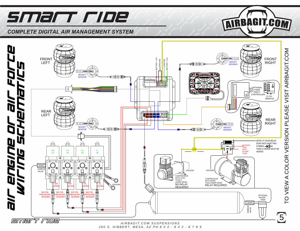
Pin 1:BLACK = GROUNDPin2: RED = BATTERY +12VPin 3: BLACK = GROUNDPin 4: YELLOW = COMP. OUT +12V/40A.This output is only designed to control a compressor with less than a 40 amp load. LARGER COMPRESSORS MUST HAVE A RELAY INSTALLED BETWEEN THE SMART-RIDE AND THE COMPRESSOR.SEE WIRING SCHEMATICSPin 5: WHITE = IGNITION +12VPin 6: GREEN = COMPRESSOR POWER +12V
3
POWER LOOM
BLACK = FRONT LEFT UPWHITE = FRONT LEFT DOWNBLUE = FRONT RIGHT UPGREY = FRONT RIGHT DOWNYELLOW = REAR LEFT UPBROWN = REAR LEFT DOWNPURPLE = REAR RIGHT UPGREEN = REAR RIGHT DOWN
VALVE LOOMTANK
LEFT REARLEFT FRONT
RIGHT REARRIGHT FRONT
PRESSURESENDER
(RED)HEIGHT
SENSORS (BLUE)LEFT REAR
LEFT FRONTRIGHT REAR
RIGHT FRONT
LCD CONTROLLER
PRESET 1 = BLACKPRESET 2 = BROWN
PRESET 3 = REDPRESET 4 = ORANGEPRESET 5 = YELLOWFRONT UP = GREEN
FRONT DOWN = BLUEREAR UP = PURPLE
REAR DOWN = GRAYCOMPRESSOR = WHITE
OPTIONAL INPUTS+12V
4.76
1.97
INFLATE ALLFOUR AIR BAGS
SMART-RIDE BUTTONEnter into setup screens
COMPRESSOR RAN FORMORE THAN 5 MINS.
SCROLL LEFTTHROUGH SETUP
SCREEN
SCROLL RIGHTTHROUGH SETUP
SCREEN
FRONTLEFT MANUAL
CONTROL
FRONTRIGHT MANUAL
CONTROL
REARLEFT MANUAL
CONTROL
COMPRESSORINDICATOR
BLUE = RUNNINGGREEN = IDLERED = ALARM
ON = BATTERYIS BELOW 10.5v
LOW BATTERYINDICATOR
DEFLATE ALLFOUR AIR BAGS
MANUALCOMPRESSOR
ACTIVATION
5 USER PRESETSSingle Press will display Preset LevelsDouble Press will activate the Preset
REARRIGHT MANUAL
CONTROL
1

2
REMOVE SCREWS ANDROTATE TOP BRACE TOGAIN ACCESS TO THESMART-RIDE RELAYCONTROL BOX
ROUTE SMART-RIDE’S REDPOWER WIRE, BOTH BLACK, GROUND WIRES, THEGREEN POWER WIRE, HEIGHT SENSOR LOOMSAND LCD CONTROLLER CABLE THROUGH GROMMET
ROUTE AIRBAG AIRLINESTHROUGH LARGE GROMMET
CHECKED VALVE INLET PLUMB TO TANK
PLUG MAIN POWERHARNESS IN BEFORECONNECTING THE LCDCONTROLLER
FRRL
FL
RR
1. Disconnect the negative battery terminal.2. Remove top of Plug n Play by removing external screws with supplied bit.3. Mount the Plug n Play in a dry location. It is recommended that you leave 5.5”-6” of room free in front of the PnP for valve removal.4. Install tank and connect a line to the tank from the compressor and a second line back to checked inlet of the PnP.5. Install tank pressure sender. Use the supplied Spanner Wrench to tighten the sender. Do not Overtighten. 6. Route the sender wire from the sender through the Plastic Grommit and into the PnP. Plug the connector in.(See Figure below)7. Route Airbag airlines through the large grommet and connect to the valves. See figure below for valve assignments.8. Run the 8 gauge power wire to the battery and connect through the supplied 60Amp brearker. Also, make sure the ground wire is connected to a clean part of the frame.9. Route a seperate power wire from the battery to Red and Green Power wire of the Smart-Ride.10. Route the 2 Smart-Ride ground wires out of the PnP Box and connect them to the same ground point as the PnP Ground.11. Connect the Smart-Ride’s White wire to the cars ignition.12. Locate a safe position for the LCD controller to be mounted. The controller can also remain loose and be handheld. Make sure the controller isn’t in a position where it can be accidentally activated while driving.13. Route the LCD controller wire loom from the controller to the Plug n Play. The loom will pass through the small plastic grommet in the middle top of the Plug n Play. Do not plug LCD loom into the Relay control box yet.14. Plug the Red and Black power connection into the Plug n Play.15. Connect the vehicles battery. 16. Plug the LCD Controller into the Relay control box. The LCD display will turn on the run through its intialization process. Once the LCD turns on the compressor will start filling the tank. The display will show the tank pressure and the individual bag pressures. The height sensor will not display until they are connected.17. Test the valves to make sure they are connected correctly.18. Mount the height sensors (See Height Sensor Installation Section) and routewires through the same grommet as the LCD loom. The height display for each corner will activate when the height sensor is connected to the relay control box.19. (Optional) Connect necessary “Optional Input Loom” to the third party controller. +12V Only20. Calibrate the height sensors. (See Calibration Section).21. Reinstall Plug n Play Top.

1. Disconnect the negative battery terminal.2. Mount the Smart-Ride in a dry location away from hot exhaust and any moving components.3. Determine where the LCD Controller will be mounted.4. Connect the LCD controller to the Relay Control Box.5. Wire according to diagram on page 1. a.Power Loom i. Connect the Black wires (Pin 1 & Pin 3) to (-) Ground. ii. Connect the Red wire (Pin 2) to constant +12V. iii. Connect the Yellow (Pin 4) to the Compressor (less than 40amp) or Compressor Relay (over 40amp draw). 1.This output is only designed to supply power to a compressor that requires less than 40 amps. Larger compressors must have a relay installed in between the Smart-Ride and the Compressor. (Wiring Schematics)` iv. Connect the White wire (Pin 5)to an Ignition wire. This wire will turn the LCD Controller On. When the ignition turns on it will also activate Preset #1 if that option has been turned on (See Screen #2 instructions for details). v. Connect the Green Wire to constant +12V (Pin 6). This wire will supply power to the inter- nal relay that powers the Yellow Wire. b.Valve Loom i. Connect each wire to its corresponding valve as shown on the Non-PnP Wiring Schematic. ii. If you have purchased this Smart-Ride controller with one of Airbagit.com's Air Engine valve assemblies, or Air Force then the Valve Loom will plug right into the Air Engine's white 9 pin plug. See Air Engine Wiring Schematic. The system will now have control of the valves but will not display pressures or heights until the sensors are installed. c. Pressure Sending units (RED). (SMART-RIDE P and SMART-RIDE HP Models Only) After the each Pressure Sending unit is installed you will see the tank pressure displayed on the LCD Controller. i. Install the pressure sending units and plug into the red sockets on the relay control box as indicated on page 1. Note: Pressure Sending units are to be tightened with the included spanner wrench only, Tightening by hand will damage the sending unit.
ii. Smart-Ride P Models with speed control adjusters will need to make sure that the pres sure sender is installed between the bag and the speed control adjuster. Installing the pres sure sender after the speed control valve will cause inaccurate readings thus affecting the units ability to reach its preset values. d. Height Sensors (BLUE). (SMART-RIDE H and SMART-RIDE HP Models Only) i. SEE HEIGHT SENSOR INSTALLATION INSTRUCTIONS e. Optional Inputs (These should be installed after the system has been completely installed and setup) i. NOTE: THESE ARE ONLY TO BE CONNECTED IF YOU INTEND ON USING A THIRD PARTY CONTROLLER I.E. 12 CHANNEL REMOTE, OR ALARM SYSTEM. If you do not intend on controlling the Smart-Ride with anything other than the Smart-Ride LCD Controller then leave this loom unplugged. ii. In order to use the optional third party inputs you will need to supply each wire with +12V. This is not a constant +12V but momentary power that is supplied by a third party controller.
3

4A I R B A G I T. C O M S U S P E N S I O N S
2 6 0 S . H I B B E R T, M E S A , A Z P H . 8 0 0 - 8 4 2 - 8 7 8 9
TO V
IEW
A C
OLO
R V
ER
SIO
N P
LEA
SE
VIS
IT A
IRB
AG
IT.C
OM
12 4
56
3
MAX MAX
FILLVALVE
DUMPVALVE
GR
OU
ND
BAT
TER
Y +1
2V
IGN
ITIO
N
BAT
TER
Y +1
2V
CHECKVALVE
OPTIONALWATER
TRAP
8586
30
87A
87
GROUND
BATTERY+12V WITH60 AMPFUSE
OR
GROUND GROUND
FILLVALVE
TANK
MAX
FILLVALVE
MAX
FILLVALVE
DUMPVALVE
HEIGHTSENSOR
HEIGHTSENSOR
HEIGHTSENSOR
HEIGHTSENSOR
300 PSIPRESSURE
SENDER
300 PSIPRESSURE
SENDER
300 PSIPRESSURE
SENDER
300 PSIPRESSURE
SENDER
12 CH.REMOTE
OPTIONAL THIRD PARTY
CONTROLLER
DUMPVALVE
DUMPVALVE
COMPRESSORWITH MORETHAN 40AMP DRAWRELAY REQUIRED
COMPRESSORWITH LESSTHAN A40AMP DRAWNO RELAYREQUIRED
300 PSIPRESSURE
SENDER
RELAYCONTROL
BOX
LCD CONTROLLER
LEFTFRONT
REARLEFT
REARRIGHT
FRONTRIGHT
TANK TANK
TANK
NOTE: IF YOUR RELAY DOES NOT HAVE THISSYMBOLTHEN A DIODE MUST BE ADDED
5A I R B A G I T. C O M S U S P E N S I O N S
2 6 0 S . H I B B E R T, M E S A , A Z P H . 8 0 0 - 8 4 2 - 8 7 8 9
TO V
IEW
A C
OLO
R V
ER
SIO
N P
LEA
SE
VIS
IT A
IRB
AG
IT.C
OM
12 4
56
3
MAX
MAX
GR
OU
ND
BAT
TER
Y +1
2V
IGN
ITIO
NB
ATTE
RY
+12V
CH
EC
KVA
LVE
OPTIONALWATER
TRAP
8586
30
87A
87
GROUND
BATTERY+12VWITH60 AMPFUSE
COMPRESSORWITH MORETHAN 40AMP DRAWRELAY REQUIRED
COMPRESSORWITH LESSTHAN A40AMP DRAWNO RELAYREQUIRED
GROUND GROUND
MAXMAX HEIGHT
SENSOR
HEIGHTSENSOR
HEIGHTSENSOR
HEIGHTSENSOR
RRUP
FRUP
RLUP
FLUP
FLDOWN
RLDOWN
FR DOWN
RRDOWN
GROUND
300 PSIPRESSURE
SENDER
300 PSIPRESSURE
SENDER
300 PSIPRESSURE
SENDER
300 PSIPRESSURE
SENDER
REARRIGHT
FRONTRIGHTLEFT
FRONT
REARLEFT
CHECKVALVE
12 CH.REMOTE
OPTIONAL THIRD PARTY
CONTROLLER
OR
NOTE: IF YOUR RELAY DOES NOT HAVE THISSYMBOLTHEN A DIODE MUST BE ADDED

6A I R B A G I T. C O M S U S P E N S I O N S
2 6 0 S . H I B B E R T, M E S A , A Z P H . 8 0 0 - 8 4 2 - 8 7 8 9
LOWEST“B”
MAX LIFT“A”
ARMLENGTH
“AL”
AXLE
GROUND
WHEEL
MID TRAVEL“VL/2”
1. MEASURE THE SUSPENSION TRAVEL WITH YOUR AIR SYSTEM. a. DETERMINE WHICH SUSPENSION LINK IS GOING TO BE ATTACHED TO THE HEIGHT SENSOR b. INFLATE THE SUSPENSION TO MAXIMUM PRESSURE OR MAXIMUM LIFT. c. MEASURE THE DISTANCE FROM THE FRAME SIDE LINK PIVOT POINT OF THE LINK TO THE GROUND. d. WRITE DOWN THIS MEASUREMENT IN BOX "A". e. DEFLATE THE SUSPENSION TO ITS LOWEST POINT. f. MEASURE THE DISTANCE FROM THE SAME PIVOT POINT TO THE GROUND. WRITE DOWN THIS MEASUREMENT IN BOX "B". g. SUBTRACT “A” AND “B” TO GET THE VERTICLE LIFT. WRITE THIS DOWN IN BOX "VL". h. RAISE THE VEHICLE HALF WAY UP SO THAT THE FRAME SIDE PIVOT IS EQUAL TO HALF OF "VL". i. MEASURE THE DISTANCE BETWEEN THE PIVOT BOLTS ON THE LINK AND WRITE THIS DOWN IN BOX "AL".

7 A I R B A G I T. C O M S U S P E N S I O N S
2 6 0 S . H I B B E R T, M E S A , A Z P H . 8 0 0 - 8 4 2 - 8 7 8 9
"A" "B" "VL" 3.00 "VL"MIN.
MOUNTINGDISTANCE
"AL" 4.25 "VL"MAX.
MOUNTINGDISTANCE
"AL"
4.50
3.76
3.02
95°
TRY TO USE AS MUCH OF THE SENSORS TRAVEL AS POSSIBLE
WITHOUT EXCEEDINGTRAVEL LIMITS
2. COMPLETE THE EQUATIONS BELOW TO GET THE OPTIMAL RANGE FOR MOUNTING THE HEIGHT SENSORS LINK-AGE. THIS OPTIMAL RANGE IS MEASURED FROM THE FRAME SIDE PIVOT OUT TOWARD THE WHEEL.3. MOVE THE SUSPENSION TO ITS MID-TRAVEL POSITION, PICK A POINT INSIDE THE OPTIMAL RANGE FOUND IN THE PREVIOUS STEPS. LOCATE A SECOND POINT ON THE FRAME THAT IS 90 DEGREES ABOVE THE PREVIOUS POINT AS SHOWN IN THE ILLUSTRATION BELOW.4. MEASURE THE DISTANCE BETWEEN THE SPOT ON THE FRAME AND THE SPOT ON THE LINK. SUBTRACT 3/4" FROM THIS DISTANCE AND CUT THE SUPPLIED THREADED ROD TO THIS LENGTH.
MAX.
MIN.
AXLE
FRAME
OPTIMALRANGE
MAX
90
8A I R B A G I T. C O M S U S P E N S I O N S
2 6 0 S . H I B B E R T, M E S A , A Z P H . 8 0 0 - 8 4 2 - 8 7 8 9
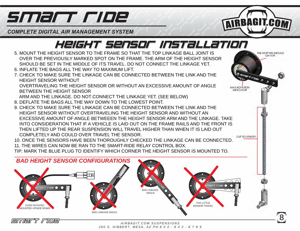
5. MOUNT THE HEIGHT SENSOR TO THE FRAME SO THAT THE TOP LINKAGE BALL JOINT IS OVER THE PREVIOUSLY MARKED SPOT ON THE FRAME. THE ARM OF THE HEIGHT SENSOR SHOULD BE SET IN THE MIDDLE OF ITS TRAVEL. DO NOT CONNECT THE LINKAGE YET.6. INFLATE THE BAGS ALL THE WAY TO MAXIMUM LIFT. 7. CHECK TO MAKE SURE THE LINKAGE CAN BE CONNECTED BETWEEN THE LINK AND THE HEIGHT SENSOR WITHOUT OVERTRAVELING THE HEIGHT SENSOR OR WITHOUT AN EXCESSIVE AMOUNT OF ANGLE BETWEEN THE HEIGHT SENSOR ARM AND THE LINKAGE. DO NOT CONNECT THE LINKAGE YET. (SEE BELOW)8. DEFLATE THE BAGS ALL THE WAY DOWN TO THE LOWEST POINT. 9. CHECK TO MAKE SURE THE LINKAGE CAN BE CONNECTED BETWEEN THE LINK AND THE HEIGHT SENSOR WITHOUT OVERTRAVELING THE HEIGHT SENSOR AND WITHOUT AN EXCESSIVE AMOUNT OF ANGLE BETWEEEN THE HEIGHT SENSOR ARM AND THE LINKAGE. TAKE INTO CONSIDERATION THAT IF A VEHICLE IS LAID OUT ON THE FRAME RAILS AND THE FRONT IS THEN LIFTED UP THE REAR SUSPENSION WILL TRAVEL HIGHER THAN WHEN IT IS LAID OUT COMPLETELY AND COULD OVER TRAVEL THE SENSOR.10. ONCE THE SENSORS HAVE BEEN THOROUGHLY CHECKED THE LINKAGE CAN BE CONNECTED.11. THE WIRES CAN NOW BE RAN TO THE SMART-RIDE RELAY CONTROL BOX. TIP: MARK THE BLUE PLUG TO IDENTIFY WHICH CORNER THE HEIGHT SENSOR IS MOUNTED TO.
OVER ROTATEDMOUNTED UPSIDE DOWN
BAD LINKAGE ANGLE
BAD LINKAGE ANGLE
TOO LITTLESENSOR TRAVEL
BAD HEIGHT SENSOR CONFIGURATIONS

9
To Save a PresetPresets should only be set after the height sensors have been calibrated.1. Raise or Lower each corner to the desired position.2. Press the center of the Smart-Ride Button once and then the press the right side of the Smart-Ride button “>” button to enter into the Preset Setup Screen #1.3. Press whichever preset button you would like to have associated with the current position. The control-ler will beep once and save the current position.4. Press the Smart-Ride Button once to exit out of the setup screens.
To Activate a Preset1. Press the button once for the desired preset. The heights and pressure associated with that preset will flash on the LCD.2. Double press the preset button quickly to activate the preset. The button lights will flash and if the button beeper is turned on it will beep while the system is going towards the preset.
Compressor Functionality1. The Smart-Ride will send out a +12V signal when the Tank Pressure is outside the range set in Setup Screen #2.2. The compressor can be set to run whenever the tank is low or whenever the tank is low and the LCD is turned on. (See Setup Screen #2 section)2. The Smart-Ride is only capable of suppling 40amps of current to run a compressor. Any compressors requiring more than 40A will require a relay to be installed between the Smart-Ride and the compressor. NOTE: UNLESS YOUR RELAY CAME WITH A BUILT IN DIODE, THEN A DIODE NEEDS TO BE INSTALLED. 3. The Compressor will run for only 5 mins at a time and then turn off. This will prevent the compressor from running if there is a leak or a failed airline. The COMP light will turn red when this error has occured. In the regular control screen Press the “D” button to restart the compressor.
Restore Factory Defaults1. Press the center of the Smart-Ride Button once and then the press the right side of the Smart-Ride button “>” button to enter into the Preset Setup Screen #1.2. Press and hold the “D” button for 3 seconds.
8586
30
87A
87
GROUNDYELLOWCOMP WIRE
NOTE: IF YOUR RELAY DOES NOT HAVE THISSYMBOLTHEN A DIODE MUST BE ADDED

A I R B A G I T. C O M S U S P E N S I O N S2 6 0 S . H I B B E R T, M E S A , A Z P H . 8 0 0 - 8 4 2 - 8 7 8 9
10
FRONT SPEEDLIFT00-50
FRONT SPEEDDROP00-50
REAR SPEEDLIFT00-50
REAR SPEEDDROP00-50
BUTTON LIGHTSON/OFF
LCDBACKLIGHT
COLOR BUTTONBEEP
ON/OFFIGNITION
COMPRESSORCONTROL
2 BEEPS = OFF4 BEEPS = ON
PSITOLER-ANCE00-15
TANKLOWPRESSUE TANK
HIGHPRESSUE
IGNITION RISE TOPRESET #1
0=Off1=On
12
3
4 5
7
9
0=Off1=On
PULSE ON MANUALCONTROLS
8
10
11
HEIGHT TOLERANCE
0.0-1.26
THESE SETTINGS ARE OPTIONAL AND SHOULD BE CHANGED IF FINE TUNING IS REQUIRED.
A I R B A G I T. C O M S U S P E N S I O N S2 6 0 S . H I B B E R T, M E S A , A Z P H . 8 0 0 - 8 4 2 - 8 7 8 9
11
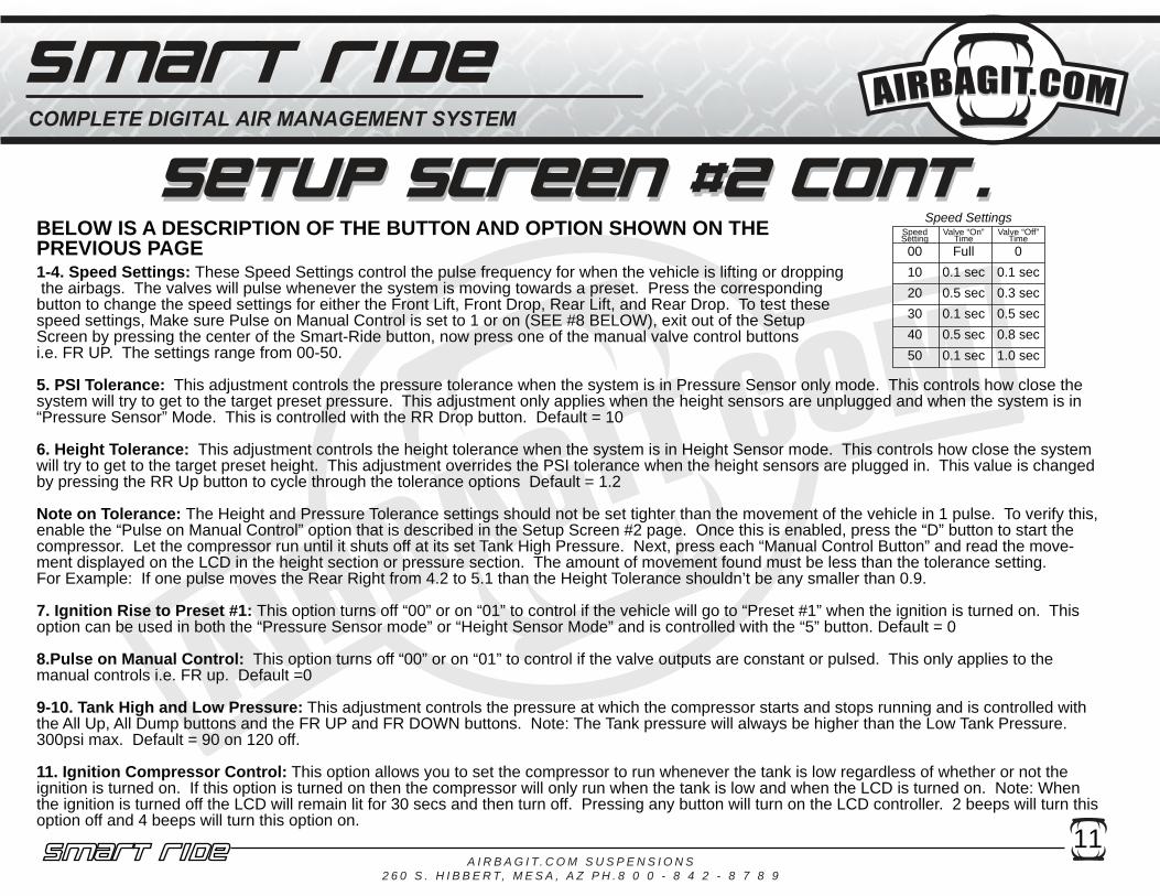
1-4. Speed Settings: These Speed Settings control the pulse frequency for when the vehicle is lifting or dropping the airbags. The valves will pulse whenever the system is moving towards a preset. Press the corresponding button to change the speed settings for either the Front Lift, Front Drop, Rear Lift, and Rear Drop. To test these speed settings, Make sure Pulse on Manual Control is set to 1 or on (SEE #8 BELOW), exit out of the Setup Screen by pressing the center of the Smart-Ride button, now press one of the manual valve control buttons i.e. FR UP. The settings range from 00-50.
5. PSI Tolerance: This adjustment controls the pressure tolerance when the system is in Pressure Sensor only mode. This controls how close the system will try to get to the target preset pressure. This adjustment only applies when the height sensors are unplugged and when the system is in “Pressure Sensor” Mode. This is controlled with the RR Drop button. Default = 10
6. Height Tolerance: This adjustment controls the height tolerance when the system is in Height Sensor mode. This controls how close the system will try to get to the target preset height. This adjustment overrides the PSI tolerance when the height sensors are plugged in. This value is changed by pressing the RR Up button to cycle through the tolerance options Default = 1.2
Note on Tolerance: The Height and Pressure Tolerance settings should not be set tighter than the movement of the vehicle in 1 pulse. To verify this, enable the “Pulse on Manual Control” option that is described in the Setup Screen #2 page. Once this is enabled, press the “D” button to start the compressor. Let the compressor run until it shuts off at its set Tank High Pressure. Next, press each “Manual Control Button” and read the move-ment displayed on the LCD in the height section or pressure section. The amount of movement found must be less than the tolerance setting.For Example: If one pulse moves the Rear Right from 4.2 to 5.1 than the Height Tolerance shouldn’t be any smaller than 0.9.
7. Ignition Rise to Preset #1: This option turns off “00” or on “01” to control if the vehicle will go to “Preset #1” when the ignition is turned on. This option can be used in both the “Pressure Sensor mode” or “Height Sensor Mode” and is controlled with the “5” button. Default = 0
8.Pulse on Manual Control: This option turns off “00” or on “01” to control if the valve outputs are constant or pulsed. This only applies to the manual controls i.e. FR up. Default =0
9-10. Tank High and Low Pressure: This adjustment controls the pressure at which the compressor starts and stops running and is controlled with the All Up, All Dump buttons and the FR UP and FR DOWN buttons. Note: The Tank pressure will always be higher than the Low Tank Pressure. 300psi max. Default = 90 on 120 off.
11. Ignition Compressor Control: This option allows you to set the compressor to run whenever the tank is low regardless of whether or not the ignition is turned on. If this option is turned on then the compressor will only run when the tank is low and when the LCD is turned on. Note: When the ignition is turned off the LCD will remain lit for 30 secs and then turn off. Pressing any button will turn on the LCD controller. 2 beeps will turn this option off and 4 beeps will turn this option on.
SpeedSetting
Valve “On”Time
Valve “Off”Time
00 Full 010 0.1 sec 0.1 sec20 0.5 sec 0.3 sec30 0.1 sec 0.5 sec40 0.5 sec 0.8 sec50 0.1 sec 1.0 sec
Speed SettingsBELOW IS A DESCRIPTION OF THE BUTTON AND OPTION SHOWN ON THEPREVIOUS PAGE

12
After installation of the height sensors a calibration is required so the Smart-Ride can better understand your suspen-sion. The calibration process converts the vehicles suspension travel into a scale 0.0 - 9.9. The Smart-Ride then displays the vehicles position based on this scale. The 0.0 - 9.9 Scale is not a reference to ride height inches.Cycle your suspension up and down to verify that the height sensors are communicating properly with the Smart-Ride system and that the height values are changing with the suspension.
Setup Screen #3 Calibrate Minimum Height.1. Lower the vehicle all the way down to its lowest point.2. Press the center of the Smart-Ride Button once and then the press the right side of the Smart-Ride button “>” button until you reach Setup Screen #3.3. Press and hold the “All” Down button until all of the height displays read 0.5. Each individual control buttons can also be used to set the display at 0.5. 4. Press the center of the Smart-Ride Button to exit out of the calibration mode.Safety Height AlarmThe software has an alarm that will beep when any of the vehicle’s height sensors are between 0.0- 1.5 and 8.5 - 9.8. This option is controlled from Setup Screen #3 by pressing the “D” button. 2 Beeps = Off and 4 Beeps = On
Setup Screen #4 Calibrate Maximum Height.1. Raise the vehicle all the way up to its highest point.2. Press the center of the Smart-Ride Button once and then the press the right side of the Smart-Ride button “>” button until you reach Setup Screen #4.3. Press and hold the “All” up button until all of the height displays read 10. Each individual control buttons can also be used to set the display at 9.8. 4. Press the center of the Smart-Ride Button to exit out of the calibration mode.

13
Functionality Tips:
1. The Tank Pressure Sender must be plugged in for the Smart-Ride to work properly.2. The Smart-Ride will attempt to move the vehicle to the requested preset for 30 seconds. After this time the system will cancel the function. If the vehicle hasn’t reached its desired preset before this 30 seconds then the flow control valves need to be adjusted to increase or decrease the speed. 3. Pressing any key while the system is moving the vehicle towards a preset will cancel the function.4. Adjusting the timing and flow control valves will allow the vehicle to lift and lower at the same speed.5. The Height and Pressure Tolerance settings should not be set tighter than the movement of the vehicle in 1 pulse. To verify this, enable the “Pulse on Manual Control” option that is described in the Setup Screen #2 page. Once this is enabled, press the “D” button to start the compressor. Let the compressor run until it shuts off at its set Tank High Pressure. Next, press each “Manual Control Button” and read the movement displayed on the LCD in the height section or pressure section. The amount of movement found must be less than the tolerance setting.For Example: If one pulse moves the Rear Right from 4.2 to 5.1 than the Height Tolerance shouldn’t be any smaller than 0.9.
Troubleshooting:
Q. Smart-Ride isn’t reading any pressures or heights and all the number in the pressure and height section are reading zeros?A. The Smart-Ride’s CPU has miscycled. Reset the system by disconnecting the barrel plug for 10 sec-onds and then plug everything back together. The main reason for this issue is from an unprotected relay, an installed regular pressure switch, or from the LCD control cable being shorted out.
Q. The compressor doesn’t turn on?A. Make sure you have your tank pressure sender installed and reading pressure on the display. Press the “D” button and see if the compressor turns on. If the compressor doesn’t turn on then check your wiring between the Smart-Ride and the compressor. If the compressor does turn on then check your high and low pressure settings. (See Setup Screen #2).
Q. The compressor is running when the key is off?A. Change the “Ignition Compressor Control” option. (See Setup Screen#2).
Q. The cables for my LCD Controller/height/pressure senders are too short?A. We have extensions that we can send out. Do not splice in a new length of wire into your connection cables.

14
124
56
3
TRIG
+ NO C NC
+12v POSITIVEGROUND
TIMER
858630
87A
87
GROUND
BATTERY+12V WITH60 AMPFUSE
GROUND
GROUND
858630
87A
87BATTERY
+12V WITH
60 AMPFUSE
GROUND
OPTIONALSECOND COMPRESSOR
1A DIODE
SMART-RIDEWITH DRYER TIMER
AND OPTIONAL SECONDCOMPRESSOR
12
4
56
3
SMART-RIDE WITHDUAL COMPRESSORS
858630
87
GROUND
GROUND
86 8530
87
GROUND
GROUND
1N4001 1N4001DIODEDIODE
BATTERY+12V WITH
60 AMP FUSE
NOTE: EACH COMPRESSOR NEEDS TO HAVE ITS OWN POWER WIRE AND FUSE
BATTERY+12V WITH
60 AMP FUSE


![Robots, Smart Homes and Ride Shares - EXL Service · [ Robots, Smart Homes and Ride Shares ] • The emerging “Internet of Things” uses sensors and wireless networks to create](https://static.fdocuments.us/doc/165x107/5f0f337a7e708231d442fc9d/robots-smart-homes-and-ride-shares-exl-service-robots-smart-homes-and-ride.jpg)