TH2683A Insulation Resistance Meter - tonghui.com.cn · TH2683A Insulation Resistance Meter is an...
62
OPERATION MANUAL TH2683A Insulation Resistance Meter C C C h h h a a a n n n g g g z z z h h h o o o u u u T T T o o o n n n g g g h h h u u u i i i E E E l l l e e e c c c t t t r r r o o o n n n i i i c c c C C C o o o . . . , , , L L L t t t d d d . . . A A A d d d d d d : : : No.3, Tianshan Road, New District, Changzhou, Jiangsu T T T e e e l l l : : : ( ( ( 0 0 0 5 5 5 1 1 1 9 9 9 ) ) ) 8 8 8 5 5 5 1 1 1 3 3 3 2 2 2 2 2 2 2 2 2 2 2 2 , , , 8 8 8 5 5 5 1 1 1 1 1 1 3 3 3 3 3 3 4 4 4 2 2 2 F F F a a a x x x : : : ( ( ( 0 0 0 5 5 5 1 1 1 9 9 9 ) ) ) 8 8 8 5 5 5 1 1 1 0 0 0 9 9 9 9 9 9 7 7 7 2 2 2 E E E - - - m m m a a a i i i l l l : : : S S S a a a l l l e e e s s s @ @ @ t t t o o o n n n g g g h h h u u u i i i . . . c c c o o o m m m . . . c c c n n n W W W e e e b b b s s s i i i t t t e e e : : : h h h t t t t t t p p p : : : / / / / / / w w w w w w w w w . . . t t t o o o n n n g g g h h h u u u i i i . . . c c c o o o m m m . . . c c c n n n
Transcript of TH2683A Insulation Resistance Meter - tonghui.com.cn · TH2683A Insulation Resistance Meter is an...

OOPPEERRAATTIIOONN MMAANNUUAALL
TH2683A Insulation Resistance Meter
CCChhhaaannngggzzzhhhooouuu TTTooonnnggghhhuuuiii EEEllleeeccctttrrrooonnniiiccc CCCooo... ,,, LLLtttddd...
AAAdddddd::: No.3, Tianshan Road, New District, Changzhou, Jiangsu
TTTeeelll :::(((000555111999)))888555111333222222222222,,,888555111111333333444222
FFFaaaxxx:::(((000555111999)))888555111000999999777222
EEE---mmmaaaiii lll ::: SSSaaallleeesss@@@tttooonnnggghhhuuuiii ...cccooommm...cccnnn
WWWeeebbbsssiii ttteee::: hhhttt tttppp::: /// /// wwwwwwwww... tttooonnnggghhhuuuiii ...cccooommm...cccnnn
TH2683A Operation Manual Ver.1.3
Contents
Contents
1) Introduction to Instrument, Unpacking and Installing ...................................................... 1
1.1 Introduction to Instrument ................................................................................. 1
1.2 Unpacking ........................................................................................................... 1
1.3 Power Connection .............................................................................................. 1
1.4 Fuse ..................................................................................................................... 2
1.5 Environment ....................................................................................................... 2
1.6 Use of Test Fixture .............................................................................................. 2
1.7 Warm‐up ............................................................................................................. 2
1.8 Other Features .................................................................................................... 2
2) Introduction to Front and Rear Panels .............................................................................. 3
2.1 Introduction to Front Panel ................................................................................ 3
2.2 Introduction to Rear Panel ................................................................................. 4
2.3 Display Zone ....................................................................................................... 5
2.4 Introduction to Buttons on Front Panel ............................................................. 6
2.4.1 [MEAS] ................................................................................................................ 6
2.4.2 [SYSTEM] ............................................................................................................. 6
2.5 Simple Operation ................................................................................................ 6
2.6 Starting Up .......................................................................................................... 7
3) Basic Operation ................................................................................................................. 9
3.1 <MEAS DISP> ...................................................................................................... 9
3.1.1 Measurement Functions ................................................................................... 10
3.2 <MEAS SETUP> ................................................................................................. 10
3.2.1 OUTP VOLT ....................................................................................................... 11
3.2.2 MEAS MODE ..................................................................................................... 12
3.2.3 CHAR TIME ........................................................................................................ 12
3.2.4 MEAS SPEED ..................................................................................................... 13
3.2.5 RANGE SET ........................................................................................................ 13
3.2.6 LOCK RANGE ..................................................................................................... 13
3.2.7 CONT CHEC ....................................................................................................... 14

TH2683A Operation Manual Ver.1.3
Contents
3.2.8 OPEN CLR .......................................................................................................... 14
3.2.9 Average ............................................................................................................. 15
3.2.10 MEAS DISP ........................................................................................................ 15
3.3 <PICKOUT SETUP> ............................................................................................ 16
3.3.1 PICK FUNC ......................................................................................................... 16
3.3.2 PICK ITEM .......................................................................................................... 17
3.3.3 LOLI ONE ........................................................................................................... 17
3.3.4 BEEP SET ........................................................................................................... 17
3.3.5 Steps for BIN Disp ............................................................................................. 18
3.3.6 Steps for PICK LIVA ........................................................................................... 18
3.3.7 Steps for OUTP RESU ........................................................................................ 19
3.3.8 PULSE WID ........................................................................................................ 19
3.4 Start Test ........................................................................................................... 19
3.4.1 Test Method ..................................................................................................... 19
3.4.2 Operation Process ............................................................................................ 20
3.4.3 Range Selection ................................................................................................ 21
4) System Setup and File Manage ....................................................................................... 22
4.1 System Setup .................................................................................................... 22
4.1.1 BEEPER .............................................................................................................. 22
4.1.2 PASSWORD ....................................................................................................... 22
4.1.3 BUS MODE ........................................................................................................ 23
4.1.4 LANGUAGE .............................................................................................................. 23
4.1.5 KEYSOUND ........................................................................................................ 24
4.1.6 TRIGER .............................................................................................................. 24
4.1.7 BAUD RATE ....................................................................................................... 24
4.1.8 HANDLER VCC ................................................................................................... 25
4.1.9 Setting Time and Date ...................................................................................... 25
4.2 <File Manage> .................................................................................................. 25
4.2.1 Introduction to Save/Recall .............................................................................. 25
4.2.2 Structure of File Folder/File in a U Disk ............................................................ 26

TH2683A Operation Manual Ver.1.3
Contents
5) Performance Index .......................................................................................................... 30
5.1 Measurement Function .................................................................................... 30
5.1.1 Measurement Parameters and Notations ........................................................ 30
5.1.2 Range ................................................................................................................ 30
5.1.3 Trigger ............................................................................................................... 30
5.1.4 Mode of Test Terminal ..................................................................................... 30
5.1.5 Measurement Speed (when MEAS DISP & BIN DISP is set as OFF) .................. 30
5.1.6 Display Digits .................................................................................................... 31
5.2 Test Signal ......................................................................................................... 31
5.2.1 Output Voltage Range ...................................................................................... 31
5.2.2 Output Voltage Accuracy .................................................................................. 31
5.2.3 Maximum Display Range .................................................................................. 31
5.3 Measurement Accuracy .................................................................................... 31
5.3.1 Basic Accuracy for Resistance Measurement ................................................... 32
6) Remote Control ............................................................................................................... 33
6.1 RS232C Connection .......................................................................................... 33
6.2 SCPI (Standard Commands for Programmable Instruments) ........................... 34
6.3 USBTMC Remote Control System ..................................................................... 34
6.3.1 System Configuration ....................................................................................... 34
6.3.2 Install the Driver ............................................................................................... 35
6.4 USBVCOM Virtual Serial Port ............................................................................ 36
6.4.1 System Configuration ....................................................................................... 36
6.4.2 Installing Driver ................................................................................................. 36
7) SCIP Command Reference ............................................................................................... 38
7.1 TH2683A Subsystem Commands ...................................................................... 38
7.1.1 DISPlay Subsystem Commands ......................................................................... 38
7.1.2 FUNCtion Subsystem Commands ..................................................................... 39
7.1.3 DISCharge Subsystem Commands .................................................................... 44
7.1.4 TRIGger Subsystem Commands ........................................................................ 44
7.1.5 FETCH? Subsystem Commands ........................................................................ 45

TH2683A Operation Manual Ver.1.3
Contents
7.1.6 COMParator Subsystem Commands ................................................................ 46
7.1.7 SYSTem Subsystem Commands ........................................................................ 50
7.1.8 Mass MEMory Subsystem Commands ............................................................. 51
7.2 GPIB Common Comamnds ............................................................................... 51
8) Handler Interface ............................................................................................................ 53
9) Package Contents and Warranty ..................................................................................... 56
9.1 Package Contents ............................................................................................. 56
9.2 Marks ................................................................................................................ 56
9.3 Package ............................................................................................................. 56
9.4 Shipping ............................................................................................................ 57
9.5 Storage .............................................................................................................. 57
9.6 Warranty ........................................................................................................... 57
Declaration
The descriptions contained in this manual may not cover all information about this instrument.
Introductions to the improvements of the instrument in performance, function, internal structure,
outer appearance, accessories, packing material, etc. are subject to change without notice. If you
find any inconformity of this manual with our instruments, please contact us for further
consultation by the address listed on the cover.

TH2683A Operation Manual Ver.1.3
1
1) Introduction to Instrument, Unpacking and
Installing
Thank you for your purchase and use of our products! This chapter will introduce the basic
instrument performance, which is followed by notes of unpacking and installing.
1.1 Introduction to Instrument
With touch, color LCD screen and unique insulation resistance/leakage current dual test function,
TH2683A Insulation Resistance Meter is an intelligent measurement instrument that is used for
rapid measurements on insulating properties of electronic parts and components (especially the
capacitance), dielectric material, equipments, wires, cables, etc.
TH2683A is provided with sorting output and external single pulse signal input interface, making
it easy for pipeline operation. The quipped communication interface can achieve the off‐site
operations of all functions of the instrument through microcomputer. The instrument has a
powerful anti‐jamming capability, which makes the measurement more reliable
1.2 Unpacking
Inspect the shipping container for damage after unpacking it. It is not recommended to power on
the instrument in the case of a damage container.
If the contents in the container do not conform to the packing list, notify us or your dealer.
1.3 Power Connection
1) Power supply: 90V to 121Vac (60Hz) or 198 to 242Vac (50Hz).
2) Power supply power range: ≤50VA.
3) L (line wire), N (neutral wire) and E (earth ground wire) of the power supply input socket
should correspond to the power plug of the instrument.
4) The instrument has been specially designed for decreasing noise jamming caused by the
input in AC power terminal, but it is also recommended to use it in the environment of low
noise. If noises cannot be avoided, install a power source filter please.
WARNING: To avoid injury to personnel and damage to the instrument resulting from electric
shock, do sure that the earth ground wire is safely grounded.

TH2683A Operation Manual Ver.1.3
2
1.4 Fuse
The fuse is a standard configuration, so use the included custom fuse please.
1.5 Environment
1) Do not store or use the instrument where it could be exposed to many dusts, great vibration,
direct sunshine and corrosive gas.
2) The instrument should operate under the temperature ranging from 10℃ to 40℃, relative
humidity of no greater than 90%. For high accuracy, use the instrument in the environment
above mentioned.
3) For high accuracy, do not block the left air vent so as to ensure good ventilation.
4) The instrument has been specially designed for decreasing noise jamming caused by the AC
power input, but it is also recommended to use it in the environment of low noise. If noise
cannot be avoided, install a power filter please.
5) If the instrument will not be used for a long time, please place it in the original or a similar
packing box. The environment temperature should be kept in the range of 0℃ to 40℃, and
the relative humidity should not be greater than 90%RH. The box should be located in an
airy room where it could be exposed corrosive impurities and direct sunlight.
6) Test leads on the instrument that are connected to DUTs should be kept away from strong
electromagnetic fields to avoid interference.
1.6 Use of Test Fixture
Only use the test fixture or cable made by our company, because the use of other test fixtures or
cables may result in incorrect measurement results. In addition, for good contact of DUT and
fixture, keep the test fixture or cable and pins of DUT clean.
Connect the test fixture or cable to HV (‐) and INPUT terminals on the instrument front panel.
1.7 Warm‐up
1) For accurate measurement, the warm‐up time should not be less than 30 minutes.
2) Do not turn on or off the instrument frequently. This may cause internal data confusion.
1.8 Other Features
1) Consumption: ≤50VA
2) Dimensions (W*H*D): 235mm*104mm*360mm; this dimension is the final packaging size.
3) Weight: Approx. 3.6kg

TH2683A Operation Manual Ver.1.3
3
2) Introduction to Front and Rear Panels
This chapter will describe the basic operation of TH2683A. Before using the instrument, please
read this chapter carefully.
2.1 Introduction to Front Panel
Figure 2‐1 shows the front panel of TH2683A.
POWER
1 2 3 4 5 6 7
12 11 9 810
INPUT
GUARD
(-)HV
WARNING:!
1000VDC MAX OUTPUT;
PLEASE REFER TO THE
"SAFETY SUMMARY"IN
THE OPERATION MANUAL.
MEAS SYSTEM
FILE ENTER
TESTDISCH.
TH2683A Insulation Resistance Meter
Figure 2‐1 Front Panel
1) USB interface
HOST interface of USB
2) LCD and touch screen
480*272 dot‐matrix, 24‐bit, 4.3‐inch TFT and touch LCD is used for measurement setup and
result display.
3) [MEAS]
Press [MEAS] to enter into the MEAS DISP page.
4) [FILE]
Press [FILE] to enter into the page of internal and external File Manage.
5) [SYSTEM]
Press [SYSTEM] to enter into the SYSTEM SETUP page.
6) [ENTER]
Press this key to terminate and store input data.
7) Test terminals (HV‐), INPUT, GUARD

TH2683A Operation Manual Ver.1.3
4
(HV‐): voltage output terminal
INPUT: sampling input terminal
GUARD: ground shield terminal
8) [TEST]
When the trigger mode is set as MANU (manual), pressing this key can trigger the
instrument manually.
9) [DISCH.]
Press this key to make the instrument return to discharge state from test state.
10) Universal Arrow Keys
There are four arrow keys: up, down, left and right arrow keys.
11) Trademark and Model
Show instrument trademark and model.
12) POWER
It is the power switch.
2.2 Introduction to Rear Panel
Figure 2‐2 shows the rear panel of TH2683A.
1 2 3
456
DEVICE HANDLER
RS-232C FOOT.CRATING FUSE~ T2AL110V/60Hz~220V/50Hz T1AL
RS-232C
S/N:R3-513-00016
7
Figure 2‐2 Rear Panel
1) RS232C Serial Interface
It realizes serial communication of the instrument with PC.
2) FOOT.C
External trigger signal, foot switch TH1801‐001 (optional) can be used to trigger measurement
when the trigger source is EXT.
3) Power Socket
It is used to input AC power and it is equipped with fuse socket. Fuse will be placed in fuse socket
to protect the instrument.

TH2683A Operation Manual Ver.1.3
5
4) Nameplate
It shows the instrument model.
5) Ground Terminal
This terminal connects the instrument chassis thus to protect or shield ground connection.
6) HANDLER Interface
Through HANDLER interface, an automatic test system can be conveniently constructed to realize
auto test. TH2683A will output sorting comparator result signals and link signals. Meantime,
“START” signal can be obtained through this interface.
7) USB Interface
PC can remotely control TH2683A through USB DEVICE.
2.3 Display Zone
TH2683A adopts 24‐bit 4.3‐inch LCD touch screen with a resolution of 480*272. The display
screen is divided into the following zones, as shown in figure 2‐3.
Figure 2‐3 Display zone
1. Page name
This zone shows the current page name.
2. Function zone
On measurement display page, this zone is used to show the measurement parameters
(parameters on this page can only be shown, but not be changed); on other page, it is used to
change the measurement parameters and zones after colon of functional parameters can be
touched to change.
3. Soft keys
TH2683A Operation Manual Ver.1.3
6
This zone displays the function menu corresponding to the cursor‐located zone.
4. Result display
This zone displays the measurement result and the time of each test procedures (counting down).
5. Prompt information
This zone displays all prompt information.
6. Bin display
This zone displays sorting results of bins (when sorting function is ON).
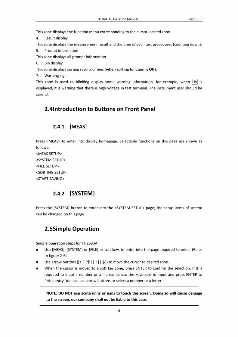
7. Warning sign
This zone is used to blinking display some warning information, for example, when HV is
displayed, it is warning that there is high voltage in test terminal. The instrument user should be
careful.
2.4 Introduction to Buttons on Front Panel
2.4.1 [MEAS]
Press <MEAS> to enter into display homepage. Selectable functions on this page are shown as
follows:
<MEAS SETUP>
<SYSTEM SETUP>
<FILE SETUP>
<SORTING SETUP>
<START SAVING>
2.4.2 [SYSTEM]
Press the [SYSTEM] button to enter into the <SYSTEM SETUP> page; the setup items of system
can be changed on this page.
2.5 Simple Operation
Simple operation steps for TH2683A:
Use [MEAS], [SYSTEM] or [FILE] or soft keys to enter into the page required to enter. (Refer
to figure 2‐5)
Use arrow buttons ([←] [↑] [→] [↓]) to move the cursor to desired zone.
When the cursor is moved to a soft key zone, press ENTER to confirm the selection. If it is
required to input a number or a file name, use the keyboard to input and press ENTER to
finish entry. You can use arrow buttons to select a number or a letter.
NOTE: DO NOT use acute units or nails to touch the screen. Doing so will cause damage
to the screen, our company shall not be liable to this case.

TH2683A Operation Manual Ver.1.3
7
2.6 Starting Up
Ensure the power earth (ground) wire is grounded, plug into a 3‐wire power socket. Press down
the power switch on the bottom left corner of the front panel, the instrument will be started up
and a boot screen will be displayed.
Figure 2‐4 shows the boot screen of TH2683A, indicating product information such as instrument
trademark, model and version.
Figure 2‐4 TH2683A Boot Screen
If the password protection is enabled, you will be asked to input your password. After inputting
your password, press [ENTER] to enter into the main menu page.
NOTE: This series of products have enabled password protection and the default password is
2683. You can reset the password by yourself. Refer to the password function on <SYSTEM
SETUP> page for more details.

TH2683A Operation Manual Ver.1.3
8
Figure 2‐5 TH2683A Main Display

TH2683A Operation Manual Ver.1.3
9
3) Basic Operation
3.1 <MEAS DISP>
Touch the screen or press down [MEAS] and then the <MEAS DISP> page will be displayed on the
screen shown as figure 3‐1.
Figure 3‐1 Measure Display
The following functions can be achieved by touching the related key in soft key area on this page.
MEAS SETUP (entering into the measurement setup page)
SYSTEM SETUP (entering into the system setup page)
FILE SETUP (entering into the internal file setup page)
PICKOUT SETUP (entering into the pick out setup page)
START Save (the current measurement results will be saved to U‐disk by pressing this touch
key. If there is no U‐disk inserted in the interface, the measurement results will not be saved;
if there is U‐disk, the touch key of START Save will change into STOP Save and it will stop
saving the data into U‐disk by pressing the touch key of STOP Save).
NOTE: Be sure to press STOP Save to end saving after START Save. Otherwise, the data may be
lost.
The following test condition information will be displayed in measurement/condition display zone
on this page. These conditions (except the measurement internal resistance) can be set on <

TH2683A Operation Manual Ver.1.3
10
MEAS SETUP> page.
MEAS STEP.
RANGE.
OUTP VOLT.
MONI VOLT.
MEAS MODE.
INTER RES.
3.1.1 Measurement Functions
Measurable parameters on TH2683A are as follows:
Primary Parameters
R (Insulation resistance)
I (Leakage current)
Secondary Parameter
T (Time count value of each procedure)
The measurement results of primary parameters and secondary parameter are respectively
displayed in three lines in the form of large characters. The upper two lines indicate the primary
parameters, while the lower line shows the secondary parameter.
Note:
1. Settings and modifications of all functions can be taken by the following steps: 1): Touch the
corresponding function zone and then select the desired function in the soft key zone on
the right side of the screen; 2): Use arrow buttons and [ENTER] button to set and modify
the corresponding function.
2. Settings and modifications of all functions can only be taken in discharging state. Only
discharging key and start saving function response in measurement state.
3.2 <MEAS SETUP>
Touch the main menu and then touch the soft key <MEAS SETUP> to enter into the <MEAS
SETUP> page shown as figure 3‐2.
TH2683A Operation Manual Ver.1.3
11
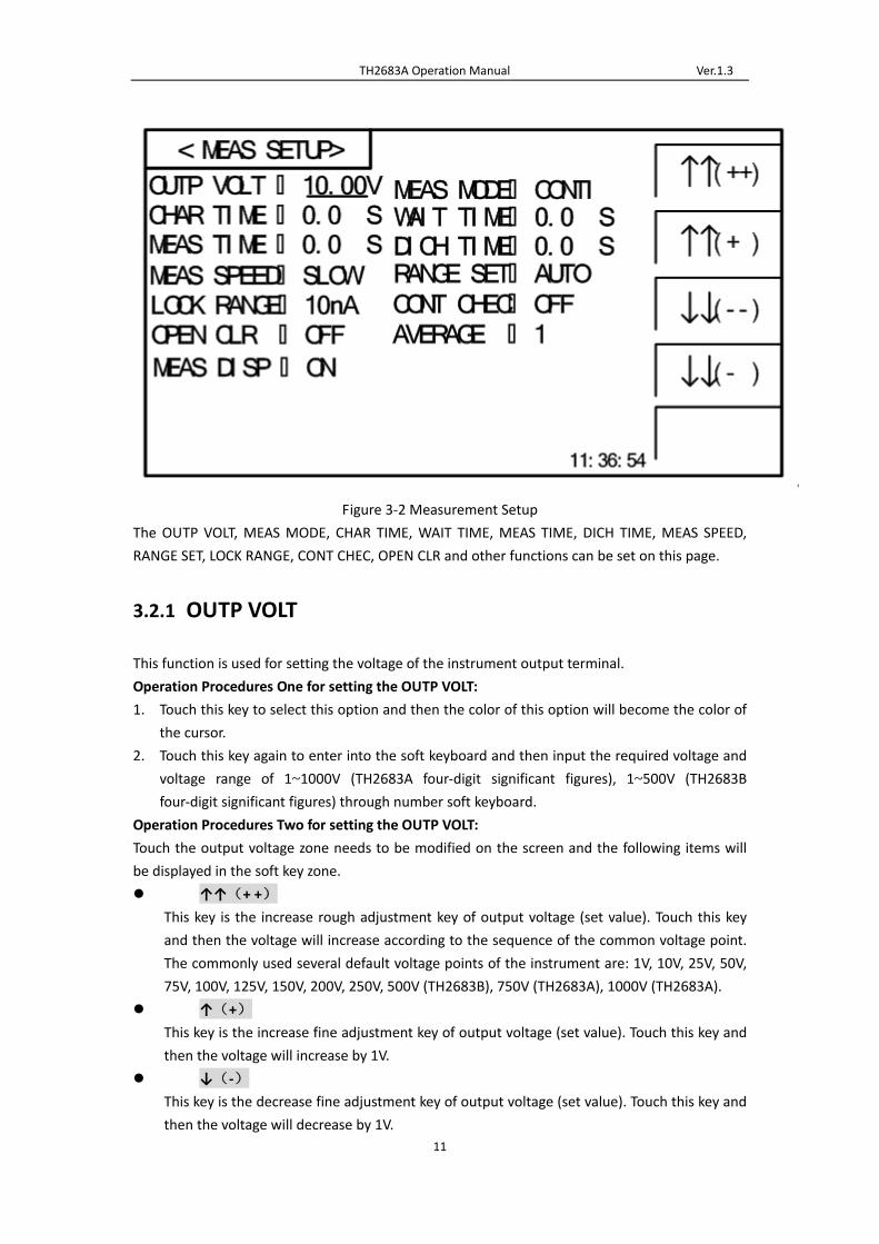
Figure 3‐2 Measurement Setup
The OUTP VOLT, MEAS MODE, CHAR TIME, WAIT TIME, MEAS TIME, DICH TIME, MEAS SPEED,
RANGE SET, LOCK RANGE, CONT CHEC, OPEN CLR and other functions can be set on this page.
3.2.1 OUTP VOLT
This function is used for setting the voltage of the instrument output terminal.
Operation Procedures One for setting the OUTP VOLT:
1. Touch this key to select this option and then the color of this option will become the color of
the cursor.
2. Touch this key again to enter into the soft keyboard and then input the required voltage and
voltage range of 1~1000V (TH2683A four‐digit significant figures), 1~500V (TH2683B
four‐digit significant figures) through number soft keyboard.
Operation Procedures Two for setting the OUTP VOLT:
Touch the output voltage zone needs to be modified on the screen and the following items will
be displayed in the soft key zone.
↑↑(+ +)
This key is the increase rough adjustment key of output voltage (set value). Touch this key
and then the voltage will increase according to the sequence of the common voltage point.
The commonly used several default voltage points of the instrument are: 1V, 10V, 25V, 50V,
75V, 100V, 125V, 150V, 200V, 250V, 500V (TH2683B), 750V (TH2683A), 1000V (TH2683A).
↑(+)
This key is the increase fine adjustment key of output voltage (set value). Touch this key and
then the voltage will increase by 1V.
↓(‐)
This key is the decrease fine adjustment key of output voltage (set value). Touch this key and
then the voltage will decrease by 1V.

TH2683A Operation Manual Ver.1.3
12
↓↓(‐ ‐)
This key is the decrease rough adjustment key of output voltage (set value). Touch this key
and then the voltage will decrease according to the sequence of the common voltage point.
The commonly used several default voltage points of the instrument are: 1V, 10V, 25V, 50V,
75V, 100V, 125V, 150V, 200V, 250V, 500V (TH2683B), 750V (TH2683A), 1000V (TH2683A).
3.2.2 MEAS MODE
This function is used for setting the measurement mode of the instrument.
Steps for setting the MEAS MODE:
Touch the corresponding zone. The following items will be displayed in the soft key zone.
SINGLE
It is used for setting the measurement mode of the instrument as SINGLE.
CONTI
It is used for setting the measurement mode of the instrument as CONTI.
Touch the corresponding key in soft key zone to select the relevant function.
3.2.3 CHAR TIME
This function is used for setting the charge time of the instrument.
Operation Procedures One for setting the CHAR TIME:
1. Touch this key to select this option and then the color of this option will become the color of
the cursor.
2. Touch this key (cursor) again to enter into the number soft keyboard, input the required
charge time (correct to 0.1s) through number soft keyboard and then press the ENTER key to
confirm and return to <MEAS SETUP> page.
Operation Procedures Two for setting the CHAR TIME:
Touch the time zone needs to be modified on the screen and the following items will be displayed
in the soft key zone.
↑↑(+ +)
Touch this key and then the instrument will increase the charge time (set value) rapidly by
10s.
↑(+)
Touch this key and then the instrument will increase the charge time (set value) by 1s.
↓(‐)
Touch this key and then the instrument will decrease the charge time (set value) by 1s.
↓↓(‐ ‐)
Touch this key and then the instrument will decrease the charge time (set value) rapidly by
10s.
Steps for setting the WAIT TIME, MEAS TIME and DICH TIME are the same as CHAR TIME. The
setting range of CHAR TIME, WAIT TIME, MEAS TIME and DICH TIME is 0~999s. When the time is
set as 0s, this step (details for measurement procedures please refer to 3.4.2) is closed.

TH2683A Operation Manual Ver.1.3
13
3.2.4 MEAS SPEED
This function is used for setting the measurement speed of the instrument.
Steps for setting the MEAS SPEED:
Touch the corresponding zone. The following items will be displayed in the soft key zone.
FAST
It is used for setting the MEAS SPEED as FAST.
SLOW
It is used for setting the MEAS SPEED as SLOW.
Touch the corresponding key in soft key zone to select the relevant function.
3.2.5 RANGE SET
This function is used for setting the range selection mode of the instrument.
Steps for setting the RANGE SET:
Touch the corresponding zone. The following items will be displayed in the soft key zone.
AUTO
It is used for setting the range selection mode as AUTO.
LOCK
It is used for setting the range selection mode as LOCK.
Touch the corresponding key in soft key zone to select the relevant function.
3.2.6 LOCK RANGE
This function is used for selecting the lock range of the instrument.
Steps for setting the LOCK RANGE:
Touch the corresponding zone. The following items will be displayed in the soft key zone.
1mA
It is used for setting the LOCK RANGE as AUTO.
100UA
It is used for setting the LOCK RANGE as 100UA.
10uA
It is used for setting the LOCK RANGE as 10uA.
1uA
It is used for setting the LOCK RANGE as 1uA.
More
Touch this key and then the following items will be displayed in the soft key zone:
100nA
It is used for setting the LOCK RANGE as 100nA.
10nA
It is used for setting the LOCK RANGE as 10nA.
More
TH2683A Operation Manual Ver.1.3
14
Return.
Touch the corresponding key in soft key zone to select the relevant function.
NOTE: This option can be modified only when the RANGE SET is set as LOCK.
3.2.7 CONT CHEC
This function is used for setting the contact check of the instrument. As the unique contact check
function of TH2683A/TH2683B, this function can well identify the contact performance of
components for capacitance, cable and other capacitive materials and reduce the occurring of
error test. In addition, the contact check will not increase any measurement time.
When the CONT CHEC function is set as ON, NO CONT (NO CONTACT), not R or I will be displayed
on the screen if the instrument is in test mode and no capacitive material is detected.
When the CONT CHEC function is set as OFF, the instrument will test the value directly, not check
the capacitive material.
Steps for setting the CONT CHEC:
Touch the corresponding zone. The following items will be displayed in the soft key zone.
ON
It is used for setting the CONT CHEC as ON.
OFF
It is used for setting the CONT CHEC as OFF.
Touch the corresponding key in soft key zone to select the relevant function.
NOTE: The contact check function is useful when testing capacitive materials and the capacity is
larger than 100pF.
3.2.8 OPEN CLR
This function is used for operating open clear of the instrument.
Steps for setting the OPEN CLR:
Touch the corresponding zone. The following items will be displayed in the soft key zone.
ON
It is used for setting the OPEN CLR as ON. If the open clear is successful, the OPEN CLR state
changes to ON; if the open clear is failing, the OPEN CLR state keeps OFF.
OFF
It is used for setting the OPEN CLR as OFF.
Touch the corresponding key in soft key zone to select the relevant function.
NOTE:
1. If the user operates the open clear successfully, the clear base used in the instrument
is the base obtained when operating this open clear; if the user operates the open clear
unsuccessfully or sets the OPEN CLR as OFF, the clear base used in the instrument is the
Factory Default.
2. When operating open clear, the user must conform to the condition described in
Chapter One—“Environment”, pull out all the test lines in test terminals and heat the
instrument for more than 30 minutes, otherwise it may result in inaccurate clear base and

TH2683A Operation Manual Ver.1.3
15
then affect the accuracy of measurement results.
3.2.9 Average
This function is used for setting the test average times of the instrument. The set range is 1~199.
Operation Procedures One for setting the CHAR TIME:
1. Touch this key to select this option and then the color of this option will become the color of
the cursor.
2. Touch this key (cursor) again to enter into the number soft keyboard, input the required
average times and then press the ENTER key to confirm and return to <MEAS SETUP> page.
Operation Procedures Two for setting the CHAR TIME:
Touch the average zone needs to be modified on the screen and the following items will be
displayed in the soft key zone.
↑↑(+ +)
Touch this key and then the instrument will increase the average times (set value) rapidly by
10.
↑(+)
Touch this key and then the instrument will increase the average times (set value) by 1.
↓(‐)
Touch this key and then the instrument will decrease the average times (set value) by 1.
↓↓(‐ ‐)
Touch this key and then the instrument will decrease the average times (set value) rapidly by
10.
NOTE:
1. When the MEAS TIME is set as 0s (i.e. this procedure is set as OFF), the Average
times can be set as 1~999.
2. When the MEAS TIME is not set as 0s (i.e. this procedure is set as ON), the set value
of the Average times is subject to the MEAS TIME. Specifically, the following restriction
rules are required:
(1) When the MEAS SPEED is set as SLOW, it takes 0.06s to make a measurement, so the
restrictive relation between the Average times and the MEAS TIME is:
Average times × 0.06 <= MEAS TIME
(2) When the MEAS SPEED is set as FAST, it takes 0.03s to make a measurement, so the
restrictive relation between the Average times and the MEAS TIME is:
Average times × 0.03 <= MEAS TIME
3. For the same reason, when setting the MEAS TIME, the above restriction rules are
also required.
3.2.10 MEAS DISP
This function is used for setting the MEAS DISP of the instrument as ON/OFF.
Steps for MEAS DISP:
Touch the corresponding zone. The following items will be displayed in the soft key zone.

TH2683A Operation Manual Ver.1.3
16
ON
It is used for setting the MEAS DISP as ON.
OFF
It is used for setting the MEAS DISP as OFF.
Touch the corresponding key in soft key zone to select the relevant function.
3.3 <PICKOUT SETUP>
Touch the soft key PICKOUT SETUP to enter into the <PICKOUT SETUP> page as shown in figure
3‐3.
Figure 3‐3 PICKOUT SETUP
The comparator functions of the instrument can be set on this page. TH2683A can set three
groups of limit values for primary parameters.
The function introduction of <PICKOUT SETUP> page
3.3.1 PICK FUNC
This function is used for controlling the switch of the instrument pickout function.
Steps for PICK FUNC:
Touch the corresponding zone. The following items will be displayed in the soft key zone.
ON
It is used for setting the PICK FUNC as ON.
OFF
It is used for setting the PICK FUNC as OFF.
Touch the corresponding key in soft key zone to select the relevant function.
NOTE: The following steps can be operated under the premise of setting the PICK FUNC as ON.

TH2683A Operation Manual Ver.1.3
17
3.3.2 PICK ITEM
This function is used for selecting the pick item of the instrument.
Steps for PICK ITEM:
Touch the corresponding zone. The following items will be displayed in the soft key zone.
CURR
It is used for setting the PICK ITEM as CURR.
RESIS
It is used for setting the PICK ITEM as RESIS.
Touch the corresponding key in soft key zone to select the relevant function.
3.3.3 LOLI ONE
This function is used for setting the lower limit value of the instrument Bin One.
Steps for setting the LOLI ONE:
1. Touch this key to select this option and then the color of this option will become the color of
the cursor.
2. Touch this key (cursor) again to enter into the number soft keyboard, input the required
lower limit value (four‐digit significant figures) and then press the ENTER key to confirm and
return to <PICKOUT SETUP> page.
The setting methods of UPLI ONE, LOLI TWO, UPLI TWO, LOLI THR and UPLI THR are the same as
LOLI ONE, the setting ranges for three groups of lower/upper limit value are:
1. When the PICK ITEM is set as CURR, the range is 1pA—1.25mA.
2. When the PICK ITEM is set as RESIS, the range is 100kΩ‐10TΩ.
3. The lower limit value of each bin cannot be larger than the upper limit value,
otherwise “please re enter due to over‐limit data” will be noticed.
4. The pickout ranges of three bins can be overlapped.
3.3.4 BEEP SET
This function is used for setting the pickout beep of the instrument.
Steps for BEEP SET:
Touch the corresponding zone. The following items will be displayed in the soft key zone.
BIN ONE
It is used for setting that the buzzer will alarm when the test value passes BIN ONE.
BIN TWO
It is used for setting that the buzzer will alarm when the test value passes BIN TWO.
BIN THREE
It is used for setting that the buzzer will alarm when the test value passes BIN THREE.
NG
It is used for setting that the buzzer will alarm when the test value of three bins fail.
OFF

TH2683A Operation Manual Ver.1.3
18
It is used for setting the PICKOUT BEEP as OFF.
Touch the corresponding key in soft key zone to select the relevant function.
NOTE:
1. The BIN ONE enjoys the top priority in the three bins, followed by BIN TWO and BIN
THREE. BIN TWO and BIN THREE will not compare when BIN ONE passes, and so on, the
test fails when all three bins fail.
2. The pickout results will be displayed on the main display interface when the PICK
FUNC is set as ON. When one of the three bins passes, the main display interface will light
up the green light and indicates BIN1, BIN2 and BIN3. When all three bins fail, the main
display interface will light up the red light and indicates FAIL.
3.3.5 Steps for BIN Disp
Touch the corresponding zone. The following items will be displayed in the soft key zone.
ON
It is used for setting the BIN Disp as ON.
OFF
It is used for setting the BIN Disp as OFF.
Touch the corresponding key in soft key zone to select the relevant function.
3.3.6 Steps for PICK LIVA
Touch the corresponding zone. The following items will be displayed in the soft key zone.
ON
It is used for setting the PICK LIVA as ON.
OFF
It is used for setting the PICK LIVA as OFF.
Touch the corresponding key in soft key zone to select the relevant function.
NOTE:
1. When the PICK LIVA is set as OFF, if the PICK ITEM is set as RESIS, the upper limit
value of BIN1, BIN2 and BIN3 will be set as infinitely great and become unchangeable and
drop out of compare, namely, the pickout changes from interval pickout to single‐point
pickout; if the PICK ITEM is set as CURR, the lower limit value of BIN1, BIN2 and BIN3 will
be set as 0 and become unchangeable and drop out of compare, namely, the pickout also
changes from interval pickout to single‐point pickout.
2. When the PICK LIVA is set as ON, whether the PICK ITEM is set as RESIS or CURR, set
the limit value according to the above steps.
3. Whether the PICK LIVA is set as ON or OFF, the priority level of BIN1, BIN2 and BIN3
keeps invariant.

TH2683A Operation Manual Ver.1.3
19
3.3.7 Steps for OUTP RESU
Touch the corresponding zone. The following items will be displayed in the soft key zone.
LEVEL
It is used for setting the OUTP RESU as LEVEL.
PULSE
It is used for setting the OUTP RESU as PULSE.
Touch the corresponding key in soft key zone to select the relevant function.
3.3.8 PULSE WID
This function is used for setting the pulse width of pulse signal for Handler PICKOUT (this item
can be changed when the OUTP RESU is set as PULSE). The setting range is 1~25ms.
Operation Procedures One for setting the PULSE WID:
1. Touch this key to select this option and then the color of this option will become the color of
the cursor.
2. Touch this key (cursor) again to enter into the number soft keyboard, input the required
pulse width and then press the ENTER key to confirm and return to <PICKOUT SETUP> page.
Operation Procedures Two for setting the PULSE WID:
Touch the average zone needs to be modified on the screen and the following items will be
displayed in the soft key zone.
↑↑(+ +)
Touch this key and then the instrument will increase the pulse width (set value) rapidly by 5.
↑(+)
Touch this key and then the instrument will increase the pulse width (set value) by 1.
↓(‐)
Touch this key and then the instrument will decrease the pulse width (set value) by 1.
↓↓(‐ ‐)
Touch this key and then the instrument will decrease the pulse width (set value) rapidly by 5.
3.4 Start Test
3.4.1 Test Method
Please connect the DUT (especially the DUT with polarity, such as the capacitor) according to the
method as shown in figure 3‐4 before testing.

TH2683A Operation Manual Ver.1.3
20
Figure 3‐4 Test connection program
NOTE:
There is voltage output in HV (‐) terminal. Please connect the DUT in discharge
condition. Beware of electric shock.
Be sure to connect the DUT with polarity (electrolytic condenser, etc.) according to the
positive and negative terminals shown in the program, otherwise it may result in the
explosion of components. Take it down after discharging for a few seconds to prevent
electric shock.
Short circuit of the instrument for a long time is not allowed; otherwise it will damage
the instrument.
In order to obtain ideal accuracy and stability, the test environment must first be
guaranteed according to the condition described in the Chapter One‐‐‐“Environment”.
3.4.2 Operation Process
1. Press TEST key to enter the test status.
2. Press DISCH. Key to finish testing and return to discharge condition.
The specific steps are as follow:
Where, the HV mark will blink in the three steps of charging, waiting and testing. The DICH mark
will blink when discharging. In addition, the three steps of charging, waiting and testing (when
the DICH TIME is set as 0s, only press the DISCH key, the system changes from test status to
discharge status) can be set as ON or OFF.
TH2683A Operation Manual Ver.1.3
21
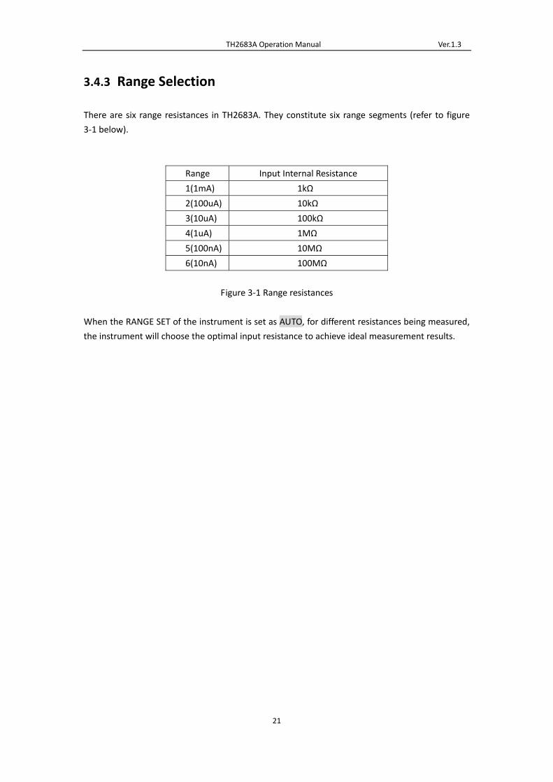
3.4.3 Range Selection
There are six range resistances in TH2683A. They constitute six range segments (refer to figure
3‐1 below).
Range Input Internal Resistance
1(1mA) 1kΩ
2(100uA) 10kΩ
3(10uA) 100kΩ
4(1uA) 1MΩ
5(100nA) 10MΩ
6(10nA) 100MΩ
Figure 3‐1 Range resistances
When the RANGE SET of the instrument is set as AUTO, for different resistances being measured,
the instrument will choose the optimal input resistance to achieve ideal measurement results.

TH2683A Operation Manual Ver.1.3
22
4) System Setup and File Manage
4.1 System Setup
Press [SYSTEM] to enter into the <SYSTEM SETUP> page as shown in figure 4‐1.
Figure 4‐1 System Setup
On this page, the following functions can be set: BEEPER, PASSWORD, BUS MODE, LANGUAGE,
TRIGER, KEYSOUND, BAUD RATE, HANDLER VCC AND TIME.
4.1.1 BEEPER
This function is used to control the switch of beeper. If the system beeps, it indicates the warning
beep of illegal key or touch.
Steps for setting the beeper:
Touch BEEPER, the following soft key zone will be displayed:
ON
Touch this key to turn on the beeper function.
OFF
Touch this key to turn off the beeper function.
You can touch soft key zone to set corresponding functions.
4.1.2 PASSWORD
This function is used to set the password.
TH2683A Operation Manual Ver.1.3
23
Steps for setting the password:
Touch PASSWORD, the following soft key zone will be displayed:
OFF
Touch this key to turn off the password protection function. This function would be disabled
only when the preset password is correctly input.
LOCK SYSTEM
Touch this key to enable the password function. Please input the password which will be
required to be input when opening a file or starting up the instrument.
LOCK FILE
It is used for file protection of users.
MODIFY
Touch this key to modify the password.
Steps for modify the password:
Touch MODIFY, a numeric keyboard will pop up then you should input the original password and
press [ENTER] to confirm. Input the new password when the numeric keyboard is shown once
again and press [ENTER] to confirm. Then the numeric keyboard will be displayed for the third
time, please input the new password. Press [ENTER] to finish the password modification.
NOTE: The default password is 2683.
4.1.3 BUS MODE
This function is used for selecting the communication interface.
Steps for setting the bus mode:
1) Touch BUS MODE, the following soft key zone will be displayed:
RS232C
USBTMC
USBVCOM
2) Touch RS232C to select the RS232C interface.
3) Touch USBTMC to select the USBTMC interface. The instrument communicates with PC
through the USB interface (USB DEVICE) on the rear panel.
4) Touch USBVCOM to select the USBVCOM interface. The instrument communicates with PC
through the USB interface (USB DEVICE) on the rear panel.
4.1.4 LANGUAGE
This function is used to set the language.
Steps for setting the language:
Touch LANGUAGE, the following soft key zone will be displayed:
English
Touch this soft key to set the language as English.
Chinese

TH2683A Operation Manual Ver.1.3
24
Touch this soft key to set the language as Chinese.
You can touch soft keys to set corresponding functions.
4.1.5 KEYSOUND
This function is used to control the key sound when the users touch the touch screen and press
the machinery keys.
Steps for setting the KEYSOUND:
Touch KEYSOUND, the following soft key zone will be displayed:
ON
Touch this key to turn on the key sound of touch screen.
OFF
Touch this key to turn off the key sound of touch screen.
You can touch soft key zone to set corresponding functions.
4.1.6 TRIGER
This function is used to select the trigger source of triggering the instrument to test.
Steps for setting the TRIGER:
Touch TRIGER, the following soft key zone will be displayed:
MAN
Press the “TEST” key on the panel, the instrument will test a DUT once and display the result.
This mode keeps in waiting mode when it is not used.
EXT
Test a DUT once and display the result when the instrument receives an external “start up”
signal from the footswitch of HANDLER interface or FOOT.C interface on the rear panel and
then enter into the waiting mode again.
BUS
The measurement of the instrument will be triggered through the communication interface.
You can touch soft key zone to set corresponding functions.
4.1.7 BAUD RATE
This function is used to select the baud rate of RS232 interface. The following twelve baud rates
are selectable: 9.60000k, 19.2000k, 28.8000k, 38.4000k, 48.0000k, 57.6000k, 67.2000k, 76.8000k,
86.4000k, 96.0000k, 105.600k and 115.200k.
Steps for setting the baud rate:
Touch BAUD RATE, the following items will be displayed in the soft key zone:
↑(+)
Touch the key to increase the baud rate.
↓(‐)
Touch the key to decrease the baud rate.
TH2683A Operation Manual Ver.1.3
25
4.1.8 HANDLER VCC
This function is used to control the VCC selection for handler interface of the instrument.
Steps for setting the HANDLER VCC:
Touch HANDLER VCC, the following soft key zone will be displayed:
INTER
It is used for setting the Handler interface powered by internal VCC.
EXTER
It is used for setting the Handler interface powered by external VCC.
You can touch soft key zone to set corresponding functions.
4.1.9 Setting Time and Date
This function is used for setting the correct time of the local time zone.
For example: 9 o’clock 13 minute and 25 second a.m. on November 12, 2010 will be shown as
10‐11‐12 09:13:25.
Operations are as follows: Touch the time zone to be modified, the following items will be
displayed.
↑↑(+ +)
Touch this key and then the time will increase rapidly by 5.
↑(+)
Touch this key and then the time will increase by 1.
↓(-)
Touch this key and then the instrument will decrease by 1.
↓↓(- -)
Touch this key and then the instrument will decrease rapidly by 5.
4.2 <File Manage>
TH2683A series can save parameters that are set by user to the internal non‐volatile memory in
the file format. User can load the file to use these parameters instead of resetting.
This section will introduce the information about the function of Save/Recall.
Notation Explanation:
E: Abbreviation of External, representing external memory, like U disk.
I: Abbreviation of Internal, representing internal memory, like internal Flash of TH2683A.
4.2.1 Introduction to Save/Recall
By the function of save/recall, user can save measurement results and configuration information
to TH2683A internal Flash or external U disk; meanwhile user can recall data from TH2683A
internal Flash or external U disk.

TH2683A Operation Manual Ver.1.3
26
Introduction to Methods and Applications of Save
The table below shows the applicable save methods and applications:
Table 4‐1 Methods and Applications of Save
Save method Recall Application
Type File format
Configuration save
(internal Flash)
*.STA Yes Save the current configuration to
internal Flash.
Configuration save
(external U disk)
*.STA Yes Save the current configuration to a U
disk.
Data save (external U
disk)
*.CSV No Save measurement results to a U
disk.
4.2.2 Structure of File Folder/File in a U Disk
Before saving data to a U disk, you are recommended to save it into a file and folder that have existed
in the memory as shown in table 4‐2. If you want to save the configuration file into a file folder in PC,
you should enter into the folder on the instrument and then take relative file operations.
Table 4‐2 Folder in U disk
Folder Maximum Amount of File Description
CSV 999 Including measurement result, like *.CSV file.
STA 999 Including configuration data, like *.STA file.
‐‐‐‐‐‐‐‐‐‐‐‐‐‐‐‐‐‐‐‐‐‐‐‐‐‐‐‐‐‐‐‐‐‐‐‐‐‐‐‐‐‐‐‐‐‐‐‐‐‐‐‐‐‐‐‐‐‐‐‐‐‐‐‐‐‐‐‐‐‐‐‐‐‐‐‐‐‐‐‐‐‐‐‐‐‐‐‐‐‐‐‐‐‐‐‐‐‐‐‐‐‐‐‐‐‐‐‐‐‐‐‐‐‐‐‐‐‐‐‐‐‐‐‐
NOTE: CSV and STA folders might be automatically generated when a U disk is connected.
Structure of Folder/File in a U disk is shown in figure 4‐2.

TH2683A Operation Manual Ver.1.3
27
Figure 4‐2 file structure in a U disk
When using a U disk on TH2683A, you should pay special attention to the following points:
1. Use a U disk with the USB2.0 interface.
2. The U disk file system should be FAT16 or FAT32. FAT16 or FAT32 standard should be used to
format the U disk. If the U disk memory exceeds 512M, it is recommended to use FAT32 standard to
format the disk.
3. Before a U disk is connected to TH2683A, you are recommended to save the data on it and
Tonghui will not be liable for the data loss.
4. In order to rapidly save the instrument data to a U disk, it is not recommended to store too
many files or folders.
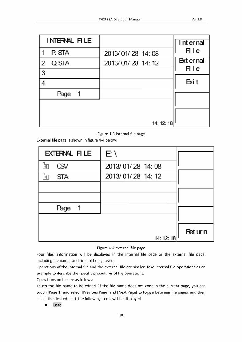
Operation Procedures
Touch FILE in any page and select File Manage to enter into the internal file page (or directly
press the FILE button on the front panel) as shown in figure 4‐3 below.
Touch [Inter File] and [External File] to respectively display files stored in the internal FLASH and
the external U disk. Touch [Exit] to exit the file manage page.
TH2683A Operation Manual Ver.1.3
28
Figure 4‐3 internal file page
External file page is shown in figure 4‐4 below:
Figure 4‐4 external file page
Four files’ information will be displayed in the internal file page or the external file page,
including file names and time of being saved.
Operations of the internal file and the external file are similar. Take internal file operations as an
example to describe the specific procedures of file operations.
Operations on file are as follows:
Touch the file name to be edited (If the file name does not exist in the current page, you can
touch [Page 1] and select [Previous Page] and [Next Page] to toggle between file pages, and then
select the desired file.), the following items will be displayed.
Load

TH2683A Operation Manual Ver.1.3
29
Touch this key, if the file name that the cursor locates is not empty, [YES] and [NO] will
be displayed in the soft key zone. When [YES] is selected, the instrument will load the
setup data in the file; when [NO] is selected, the current operation will be cancelled.
Save
Touch this key, [YES] and [NO] will be displayed in the soft key zone. When [NO] is
selected, the current operation of save file will be cancelled; when [YES] is selected, the
numerical keyboard will pop up and then you can input the file name and press [ENTER]
to finish inputting. Thus the current settings in all pages will be saved to the file. (NOTE:
When storing a file, if the inputting file number has already existed, the save
operation will overwrite the original file.)
Delete
Touch “Delete”, if “YES” is selected, the instrument will delete the file that the cursor
locates.
Copy to E:
Touch “Copy to E”. The instrument will copy the file the cursor locates or the selected
file to a U disk.
Select
Touch “Select”, the file the cursor locates will be selected. TH2683A can simultaneously
copy several files to a U disk.
Touch “Select” once again, the selected file will be cancelled from selection.
Save Measurement Results
In the “MEAS DISP” page, touch “Start Save” in soft key zone to save measurement results to a U
disk. Touch “Stop Save”, the instrument will stop saving measurement results.
Operations of External File and Folder
Operations of external file are similar to that of internal file.
Operations of external file folder are as below:
(1) Touch the name of the desired file folder to enter into the corresponding folder;
(2) Touch “Upper Page” in the right soft key zone to return to the upper page shown as
figure 4‐4 above.

TH2683A Operation Manual Ver.1.3
30
5) Performance Index
5.1 Measurement Function
5.1.1 Measurement Parameters and Notations
R:Resistance
I: Leakage current
5.1.2 Range
Resistance Mode: AUTO, MANU (HOLD, UP, DOWN)
5.1.3 Trigger
Manual, external, bus
Manual: Press the “TRIGGER” button on the panel, the instrument will test a DUT once and
display the result. This mode keeps in waiting mode when it is not used.
External: Test a DUT once and display the result when the instrument receives an external “start
up” signal from the footswitch of HANDLER interface on the rear panel.
BUS: The measurement of the instrument will be triggered through the communication interface.
5.1.4 Mode of Test Terminal
2‐terminal measurement mode
HV (‐): DCV output terminal INPUT: Sampling input terminal
5.1.5 Measurement Speed (when MEAS DISP & BIN DISP is set
as OFF)
Speed
Parameter FAST SLOW
R Meas/sec≤30ms Meas/sec≤60ms
I Meas/sec≤30ms Meas/sec≤60ms

TH2683A Operation Manual Ver.1.3
31
5.1.6 Display Digits
Item
Resistance 4‐digit significant figures
Leakage
current
Range 1:correct to 100nA
Range 2:correct to 10nA
Range 3:correct to 1nA
Range 4:correct to 100pA
Range 5:correct to 10pA
Range 6:correct to 1pA
Time Correct to 0.1s
5.2 Test Signal
5.2.1 Output Voltage Range
Max. output DVC range of TH2683A test terminal: 1 – 1000V.
Max. output DVC range of TH2683B test terminal: 1 – 500V.
5.2.2 Output Voltage Accuracy
Voltage ≥ 10V: 1% ± 1V
Voltage < 10V: 10% ± 0.1V
5.2.3 Maximum Display Range
Parameter Measurement Display Range
Resistance test 100.0kΩ ~ 10.00TΩ
Leakage current test
Range 1: 100uA ~ 1mA, input internal resistance 10kΩ
Range 2: 10uA ~ 100uA, input internal resistance 10kΩ
Range 3: 1uA ~ 10uA, input internal resistance 10kΩ
Range 4: 100nA ~ 1uA, input internal resistance 10kΩ
Range 5: 10nA ~ 100nA, input internal resistance 1MΩ
Range 6: 1nA ~ 10nA, input internal resistance 1MΩ
5.3 Measurement Accuracy
Measurement accuracy depends on measurement stability, temperature coefficient, linearity,

TH2683A Operation Manual Ver.1.3
32
repeatability and correction interpolation error.
Checking the measurement accuracy should be taken under the following circumstances:
a. Warm‐up time should be more than 30 minutes.
b. Correctly open the output terminal and perform zero clearing by pressing the
start key on the MEAS SETUP page.
5.3.1 Basic Accuracy for Resistance Measurement
SLOW, FAST: (This accuracy is obtained under the temperature of 20±5℃)
Test accuracy Voltage ≥10V and I>10nA :±2%
Voltage ≤10V or I ≤ 10nA :±5%

TH2683A Operation Manual Ver.1.3
33
6) Remote Control
6.1 RS232C Connection
RS‐232 standard, also called as asynchronous serial communication standard, has already been
widely used for data communication between computers, computer and external equipment. RS
is the English abbreviation of Recommended Standard; 232, the standard number. This standard
is issued by EIA in 1969, which rules to send one bit in a data line every time.
As most serial interfaces, the serial interface of TH2683A is also not strictly based on RS‐232
standard but only uses the smallest subset of this standard. The signals are listed in the following
table.
Table 6‐1 RS‐232 Signal and Pin Connector
The reason is that the use of three lines is much more inexpensive and much simpler than that
of five lines or six lines, which is the biggest advantage of using serial interface for
communication.
The connection of the instrument with PC is shown in figure 6‐1.
TXD(2) (3) RXD
PC
(Controller) RXD(3) (2) TXD TH2683A series
GND(5) (5) GND
Figure 6‐1 Connection of the instrument with PC
Figure 6‐1 shows that the serial interface pin definition of this instrument is different from that of
9 pin connector used in the computer. User can purchase the serial interface cable from our
company.
RS232 interface characterizes with a baud rate ranging from 9600 to 115200, no parity, 8‐bit data
bit, 1‐bit stop bit.
The instrument commands comply with the SCPI standard. When a command string is
Signal Code Connector Pin Number
Transmitted Data TXD 2
Received Data RXD 3
Signal Ground Common GND 5

TH2683A Operation Manual Ver.1.3
34
transmitted to the instrument, it is required to send LF (hexadecimal: 0AH) as the terminating
character. Each time the maximum receivable number of SPCI command string is 2kByte.
For result data formats transmitted to a PC from the instrument, see Commands Reference.
6.2 SCPI (Standard Commands for Programmable Instruments)
SCPI is a new general command based on the IEEE488.2‐1987 standard. (SCPI is the same as TMSL,
a system language for measurement testers adopted by HP.)
System for Component X System for Component Y
BUS
Relative information for measurement tester
Common commands and query
Syntax and data structure
Remote control
D C B A A B C D
IEEE488.1 Standard
SCPI SCPI
Where:Level D shows the instrument functions
Level C shows the common system functions
Level B shows the information communication functions
Level A shows the interface functions (IF)
Figure 6‐2 SCPI functions levels
6.3 USBTMC Remote Control System
USB (Universal Serial Bus) remote control system controls the instrument through the USB
interface. This connection conforms to USBTMC‐USB488 and USB2.0 protocols.
6.3.1 System Configuration
Connect USB interfaces on PC and TH2683A through a USB cable.

TH2683A Operation Manual Ver.1.3
35
6.3.2 Install the Driver
When TH2515 is first connected to a PC through a USB cable, the prompt information –Found
New Hardware will show on the right bottom of the computer desktop, as is shown below:
Figure 6‐3 Procedure 1 of Installing USB Driver
Click “NEXT”, dialogue 6‐4 will pop up. Choose “Install the software automatically
(recommended)”.
Figure 6‐4 Procedure 2 of Installing USB Driver
When the installation of driver is finished, user can see “usb test and measurement device” in the
device manager of PC, as is shown in the following figure.

TH2683A Operation Manual Ver.1.3
36
Figure 6‐5 USBTMC Display of PC Device Manager
When user is using USBTMC interface, labview software can be used to access the instrument.
6.4 USBVCOM Virtual Serial Port
When “USBVCOM” is selected, the USB interface can be configured as a virtual serial port
(VCom).
6.4.1 System Configuration
Connect PC and TH2683A to the USB interface through a USB cable.
6.4.2 Installing Driver
Methods of installing USBCDC driver are the same with that of installing USBTMC driver. When
the installation of driver is finished, user can see “usb VCom port” in the PC device manager, as is
shown in figure 6‐6.
Figure 6‐6 VCom Display of PC Device Manager

TH2683A Operation Manual Ver.1.3
37
Now, usb VCom port acts as a serial port. When PC has no serial port, the communication
software based on this serial port can be used as USB virtual serial port.

TH2683A Operation Manual Ver.1.3
38
7) SCIP Command Reference
1. Data Conventions of This Manual
NR1 :integer, for example:123
NR2 :fixed number, for example: 12.3
NR3 :floating number, for example: 12.3E+5
NL :CR character,integer: 10
^END:EOI (end) signal of IEEE‐488 bus.
7.1 TH2683A Subsystem Commands
●DISPlay ●TRIGger ●COMParator ●DISCharge ●SYSTem
●FUNCtion ●FETCh? ●Mass MEMory
NOTE: All the following commands relating to changing the instrument setup are
recommended to be used when the instrument is in discharge condition, otherwise it may result
in wrong results.
7.1.1 DISPlay Subsystem Commands
DISPlay subsystem commands are mainly used to set the instrument display page.
The :DISPlay? query returns to the current page.
Command Tree:
The :PAGE command sets the display page.
The DISPlay:PAGE? qurey returns to the current page.
Command Syntax: DISPlay:PAGE <page name>
Functions of <page name> are as follows:
MEASurement Set the display page to measurement display.
MSETup Set the display page to measurement setup.
LTABle Set the display page to pickout setup.
SYSTem Set the display page to system setup.

TH2683A Operation Manual Ver.1.3
39
FLISt Set the display page to (internal) file list.
For example: WrtCmd(“DISP:PAGE MEAS”); Set the display page to measurement display.
Query syntax: DISPlay:PAGE?
Return format: <page name><NL^END>
<page name> refer to the above set value.
7.1.2 FUNCtion Subsystem Commands
FUNCtion subsystem commands are mainly used to set the items relating to MEAS SETUP:
“voltage”, “measurement mode”, “charge time”, “wait time”, “measurement time”, “discharge
time”, “range”, “contact check” and “zero clearing”.
Command Tree:
TH2683A Operation Manual Ver.1.3
40
The :CZERo ON command is used to execute open clear zero of the instrument, “?” can query the
current zero clearing passes or fails. If this zero clearing passes, the zero base used in this
measurement is obtained from this open zero clearing; if this zero clearing fails, the zero base
used in this measurement is factory default.
The :CZERo OFF command is used to cancel the influence of the zero base toward measurement
results when users execute zero ckearing successfully. At this time, the zero base used in the
measurenment is the factory default.
Command syntax: FUNCtion: CZERo ON(1)
OFF(0)
Where,
Character 1 (integer:49) means ON.
Character 0 (integer: 48) means OFF.
For example: WrtCmd(“:FUNC:CZER:ON”); Execute open zero clearing of the instrument.
Query syntax: FUNCtion:CZERo?
Return Format:
SUCCess
<NL^END>
FAILed
The FUNCtion:CZERo? query returns to the zero clearing result (success or failed).
The : OVOLtage command sets the output voltage of the instrument.
The :FUNCtion: OVOLtage? query returns to the current output voltage of the instrument.
Command Syntax: :FUNCtion: OVOLtage <value>
Where, <value> is any real value among the output voltage range (1‐1000V) of the instrument.
For example: WrtCmd(“FUNCtion:OVOL 12.50”); set the output voltage of the instrument as
12.50V.
Query syntax: FUNCtion: OVOLtage ?
Return Format: <value><NL^END>
The :FUNCtion: OVOLtage? query returns to the current output voltage of the instrument.
The : MMODe command sets the measurement mode of the instrument.
The :FUNCtion:MMODe? query returns to the measurement mode of the instrument.
SINGle
Command Syntax:FUNCtion: MMODe
CONTinuous
Where, SINGle and CONTinuous are respectively indicate single and continuous measurement.
For example: WrtCmd(“FUNCtion:MMOD SINGle”); set the measurement mode of the
instrument as SINGle.

TH2683A Operation Manual Ver.1.3
41
Query syntax: FUNCtion: MMODe ?
SINGle
Return Format: <NL^END>
CONTinuous
The :FUNCtion: MMODe? query returns to the current measurement mode of the instrument.
The : MSPeed command sets the measurement speed of the instrument.
The :FUNCtion:MSPeed? query returns to the measurement speed of the instrument.
FAST
Command Syntax:FUNCtion: MSPeed
SLOW
Where, FAST and SLOW are respectively indicate fast and slow measurement.
For example: WrtCmd(“FUNCtion:MSP SLOW”); set the measurement speed of the instrument as
SLOW.
Query syntax: FUNCtion: MSPeed ?
FAST
Return Format: <NL^END>
SLOW
The :FUNCtion: MMODe? query returns to the current measurement speed of the instrument.
The :CCHeck command set the contact check switch of the instrument.
The FUNCtion:CCHeck? query returns to the current contact check switch of the instrument.
Command syntax:
ON(1)
FUNCtion: CCHeck
OFF(0)
Where,
Character 1 (integer:49) means ON.
Character 0 (integer: 48) means OFF.
For example: WrtCmd(“:FUNC:CCH:ON”); set the contact chcek switch of the instrument as “ON”.
Query syntax: FUNCtion:CCHeck?
Return Format:
ON
<NL^END>
OFF
The :CTTMe command set the charge time of the instrument.
The FUNCtion:CTTMe? query returns to the current charge time of the instrument.
Command syntax: FUNCtion: CTIMe <value>

TH2683A Operation Manual Ver.1.3
42
Where, <value> is any real value among the charge time range (0‐999.0s) of the instrument
(correct to 0.1s).
For example: WrtCmd(“FUNCtion:CTTM 12.5”); set the charge time of the instrument as 12.5s.
Query syntax: FUNCtion: CTTMe?
Return Format: <value><NL^END>
The :FUNCtion:CTTMe? query returns to thecharge time of the instrument.
The :WTIMe command set the wait time of the instrument.
The FUNCtion:WTIMe? query returns to the current wait time of the instrument.
Command syntax: FUNCtion: WTIMe <value>
Where, <value> is any real value among the wait time range (0‐999.0s) of the instrument (correct
to 0.1s).
For example: WrtCmd(“FUNCtion:WTIme 12.5”); set the wait time of the instrument as 12.5s.
Query syntax: FUNCtion: WTIMe?
Return Format: <value><NL^END>
The :FUNCtion:WTIMe? query returns to the wait time of the instrument.
The :MTIMe command set the measurement time of the instrument.
The FUNCtion:MTIMe? query returns to the current measurement time of the instrument.
Command syntax: FUNCtion: CTIMe <value>
Where, <value> is any real value among the measurement time range (0‐999.0s) of the
instrument (correct to 0.1s).
For example: WrtCmd(“FUNCtion:MTIMe 12.5”); set the measurement time of the instrument as
12.5s.
Query syntax: FUNCtion: MTIMe?
Return Format: <value><NL^END>
The :FUNCtion:MTIMe? query returns to the measurement time of the instrument.
The :DTIMe command set the discharge time of the instrument.
The FUNCtion:DTIMe? query returns to the current discharge time of the instrument.
Command syntax: FUNCtion: DTIMe <value>
Where, <value> is any real value among the discharge time range (0‐999.0s) of the instrument
(correct to 0.1s).
For example: WrtCmd(“FUNCtion:DTIMe 12.5”); set the discharge time of the instrument as
12.5s.
Query syntax: FUNCtion: DTIMe?
Return Format: <value><NL^END>
The :FUNCtion:DTIMe? query returns to the discharge time of the instrument.
The :AVERage command sets the measurement average time of the instrument.

TH2683A Operation Manual Ver.1.3
43
The :FUNCtion:AVERage? query returns to the current measurement average times of the
instrument.
Command syntax: FUNCtion: AVERage <value>
Where, <value> is any integer value among the average times range (1‐999) of the instrument.
For example: WrtCmd(“FUNCtion:AVERage 12”); set the average times of the instrument as 12.
Query syntax: FUNCtion: AVERage?
Return Format: <value><NL^END>
The :FUNCtion:AVERage? query returns to the average times of the instrument.
The :RANGe command sets the range of the instrument.
The FUNCtion:RANGe? query returns to the current range parameters .
Command syntax: FUNCtion: RANGe <value>
Where, <value> can be 1mA、100uA、10uA、1uA、100nA、10nA
For example: WrtCmd(“FUNC:RANG 1mA”); Set the range of the instrument as 1mA.
The :RANGe:AUTO command sets the range auto selection mode of the instrument.
The FUNCtion:RANGe:AUTO? query returns to the current range mode.
Command syntax:
ON (1)
FUNCtion:RANGe:AUTO
OFF (0)
Where,
Character 1 (integer:49) means ON.
Character 0 (integer: 48) means OFF.
For example: WrtCmd(“FUNC:RANG:AUTO ON”); Set the range mode of the instrument as AUTO.
Query syntax: FUNCtion:RANGe:AUTO?
ON
Return format: <NL^END>
OFF
The :MDISplay command sets the measurement display switch of the instrument.
The FUNCtion:MDISplay? query returns to the current measurement display switch of the
instrument.
Command syntax:
ON (1)
FUNCtion:MDISplay
OFF (0)
Where,
Character 1 (integer:49) means ON.
Character 0 (integer: 48) means OFF.
For example: WrtCmd(“FUNC:RANG:MDIS: ON”); Set the measurement display switch of the
instrument as AUTO.

TH2683A Operation Manual Ver.1.3
44
Query syntax: FUNCtion:MDISplay?
ON
Return format: <NL^END>
OFF
7.1.3 DISCharge Subsystem Commands
DISCharge [:GO]
Set the instrument to discharge.
7.1.4 TRIGger Subsystem Commands
The TRIGger subsystem commands set the instrument trigger source and the delay time after
triggering, and triggers instrument measurement.
Command Tree:
The :IMMediate command triggers a measurement.
Command syntax: TRIGger[:IMMediate]
For example:WrtCmd(“TRIG”);
The :SOURce command sets the mode of trigger source.
The :SOURce? query returns to the current mode of trigger source.
Command syntax:
EXTernal
TRIGger:SOURce BUS
HOLD
Where,
EXTernal Be triggered by the HANDLER interface.
BUS Be triggered by the RS232 interface or the USB interface (DEVICE).
HOLD Be triggered by pressing the TEST key.
For example: WrtCmd(“TRIG:SOUR BUS”);
Query syntax: TRIGger:SOURce?
Return format:

TH2683A Operation Manual Ver.1.3
45
EXT
BUS <NL^END>
HOLD
7.1.5 FETCH? Subsystem Commands
The FETCh? Subsystem commands are used to get the measurement result of TH2683A.
Command Tree:
The [:IMP]? query returns TH2683A’s last measurement result to its output buffer.
Query syntax: FETCh[:IMP]?
For example, WrtCmd (“TRIG:SOUR BUS”);
WrtCmd (“TRIG”);
WrtCmd (“FETC?”);
When the PICKOUT function is set as ON:
Data format: < insulation resistance>, < leakage current>, <pickout item>, <pickout comparator
results>,< ultralimit>
0 BIN1 passes
1 BIN2 passes
2 BIN3 passes
3 Three bins all failed
The figure below is the range value of ultralimit compare for each range (NOTE: lower limit is not
compared in range 6)
Parameter Compare range
Current
Range 1:95uA ~ 1.05mA
Range 2:9.5uA ~ 105uA
Range 3:0.95uA ~ 10.5uA
Range 4:95nA ~ 1.05uA
Range 5:9.5nA ~ 105nA
Range 6: ~ 10.5nA
Ultralimit:
0 downlap

TH2683A Operation Manual Ver.1.3
46
1 between the range
2 onlap
When the PICKOUT function is set as OFF:
Data format: <insulation resistance>, <leakage current>, <ultralimit>
Ultralimit:
0 downlap
1 between the range
2 onlap
AUTO command makes TH2683A to send each measurement result to its output buffer
automatically.
ON
OFF
Command syntax:FETCh:AUTO 1
0
For example: WrtCmd(“FETC:AUTO ON”);
The SMONitor command querys the monitor voltage.
Command syntax:FETCh:SMONitor:VOLT?
7.1.6 COMParator Subsystem Commands
COMParator subsystem commands are used to set the pickout function of the insturment,
including the setup of pickout switch and pickout list.
Command Tree:

TH2683A Operation Manual Ver.1.3
47
The :FUNCtion command is used to set the pickout function as ON or OFF. It can query the
current pickout function state.
Command syntax:
ON(1)
COMParator:FUNCtion
OFF(0)
Where,
Character 1 (integer:49) means ON.
Character 0 (integer: 48) means OFF.
For example: WrtCmd(“COMP:FUNC ON”)
Query syntax: COMParator:FUNCtion ?
Return format: <NR1><NL^END>
The :ITEM command sets the pickout item of the instrument.
COMParator:ITEM? Query returns to the current pickout item.
Command syntax:
CURRent
COMParator:ITEM
RESistance
Where,
CURRent set the pickout item as CURR

TH2683A Operation Manual Ver.1.3
48
RESistance set the pickout item as RESIS
For example: WrtCmd(“COMP:ITEM CURR”)
Query syntax: COMParator:ITEM?
Return format:
CURRent
<NL^END>
RESistance
The :Current:BIN<value> <low limit>,<high limit> and :RESistance:BIN<value> <low limit>,<high
limit> commands are usd to set the high limit and low limit when the pickout item is set as CURR
or RESIS.
Command syntax: COMParator: Current:BIN<value> <low limit>,<high limit>
Where,
<value> is the BIN No. of NR1 data format, input range: 1‐3.
<low limit> is the low limit of NR1,NR2 or NR3 data format.
<high limit> is the high limit of NR1,NR2 or NR3 data format.
For example: WrtCmd(“COMP: Current :BIN1 12.00n, 50.00n”),the default unit of resistance is
Ω and the default unit of current is A.
Query syntax: COMP: Current:BIN<n>?
Return format: <NR3>,<NR3><NL^END>
:BEEPer BONe
BTWo
BTHRee
NG
OFF
The above commands are used to specify the indication of beeper toward pickout results or turn
off the beeper function.
Command syntax:
COMParator:BEEPer BONe it beeps when the beeper passes BIN1
COMParator:BEEPer BTWo it beeps when the beeper passes BIN2
COMParator:BEEPer BTHRee it beeps when the beeper passes BIN3
COMParator:BEEPer NG it beeps when three bins of the beeper all failed
COMParator:BEEPer OFF turn off the beeper function
Query Syntax:
COMParator:BEEPer?
Return format:
BONe, BTWo, BTHRee, NG, OFF
The :BDISplay command is used to set the bin display of the instrument as ON or OFF.

TH2683A Operation Manual Ver.1.3
49
The :BDISplay? query returns to the current bin display state.
Command syntax:
ON(1)
COMParator: BDISplay
OFF(0)
Where,
Character 1 (integer:49) means ON.
Character 0 (integer: 48) means OFF.
For example: WrtCmd(“COMP:BDIS ON”)
Query Syntax: COMParator: BDISplay?
Return format: <NR1><NL^END>
The : BLIMitvalue command is used to set the bin limit value of the instrument as ON or OFF.
The: BLIMitvalue? query returns to the current bin limit value.
Command syntax:
ON(1)
COMParator: BLIMitvalue
OFF(0)
Where,
Character 1 (integer:49) means ON.
Character 0 (integer: 48) means OFF.
For example: WrtCmd(“COMP:BLIM ON”)
Query Syntax: COMParator: BLIMitvalue?
Return format: <NR1><NL^END>
The :ORESultcommand sets the bin output results type of the instrument.
COMParator:ORESult? query returns to the current bin output results type.
Command syntax:
LEVel
COMParator:ORESult
PULSe
Where,
LEVel set the bin output results type as LEVel
PULSe set the bin output results type as PULSe
For example: WrtCmd(“COMP:ORES LEV”)
Query syntax: COMParator:ORES?
Return format:
LEVel
<NL^END>
PULSe
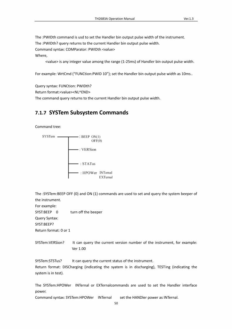
TH2683A Operation Manual Ver.1.3
50
The :PWIDth command is usd to set the Handler bin output pulse width of the instrument.
The :PWIDth? query returns to the current Handler bin output pulse width.
Command syntax: COMParator: PWIDth <value>
Where,
<value> is any integer value among the range (1‐25ms) of Handler bin output pulse width.
For example: WrtCmd (“FUNCtion:PWID 10”); set the Handler bin output pulse width as 10ms..
Query syntax: FUNCtion: PWIDth?
Return format:<value><NL^END>
The command query returns to the current Handler bin output pulse width.
7.1.7 SYSTem Subsystem Commands
Command tree:
The :SYSTem:BEEP OFF (0) and ON (1) commands are used to set and query the system beeper of
the instrument.
For example:
SYST:BEEP 0 turn off the beeper
Query Syntax:
SYST:BEEP?
Return format: 0 or 1
SYSTem:VERSion? It can query the current version number of the instrument, for example:
Ver 1.00
SYSTem:STSTus? It can query the current status of the instrument.
Return format: DISCharging (indicating the syatem is in discharging), TESTing (indicating the
system is in test).
The SYSTem:HPOWer INTernal or EXTernalcommands are used to set the Handler interface
power.
Command syntax: SYSTem:HPOWer INTernal set the HANDler power as INTernal.

TH2683A Operation Manual Ver.1.3
51
Query Syntax: SYSTem:HPOWer?
Return format: INTernal (indicating the current HANDler power is INTernal), EXTernal (indicating
the current HANDler power is EXTernal).
7.1.8 Mass MEMory Subsystem Commands
Mass MEMory subsystem commands are used to set the storing and loading of the files (specific
to the internal files).
Command tree:
Mass MEMory :LOAD :STATe <record number>
:STORe :STATe <record number>
The :LOAD:STATe command is used to load the files stored.
Command syntax: MMEMory:LOAD:STATe <value>
Where,
<value> file sequence number of 1‐20 (NR1)
For example, WrtCmd(“MMEM:LOAD:STAT 1”);
The :STORe:STATe command is used to store the current setup of the instrument to a file.
Command syntax: MMEMory:STOR:STATe <value>,<name>
Where,
<value> file sequence number of 1‐20 (NR1).
<name> file name (suffix .STA is not required, the length is less than 15
characters).
For example, WrtCmd(“MMEM:STOR:STAT 1,ABC”);
7.2 GPIB Common Comamnds
●*RST ●*TRG ●*IDN
The *RST command resets the instrument.
Command syntax: *RST
For example: WrtCmd(“*RST”);
The *TRG command triggers the measurement and then sends the result to the output
buffer.
Command syntax: *TRG
For example: WrtCmd(“*TRG”);
NOTE: ”*trg” will be valid when :INIT:CONT ON and trig:sour bus commands are enabled.
The *IDN? query returns TH2683A’s identification string.
Query syntax: *IDN?
Return format: <manufacturer>,<model>,<firmware><NL^END>

TH2683A Operation Manual Ver.1.3
52
Where,
<manufacturer> Name of Manufacturer ( Tonghui)
<model> Instrument Model (TH2683A/TH2683B)
<firmware> Firmware Version (Version 1.0.0)
For example: WrtCmd(“*IDN?”);

TH2683A Operation Manual Ver.1.3
53
8) Handler Interface
TH2683A Insulation Resistance Meter equips with a Handler interface which is mainly used to
output the sorting result. When the instrument is applied to an automatic component sorting
test system, this interface will output the handshake signal and the sorting result output signal.
The sorting result output corresponds to the comparison result output of the current comparator
bin.
Terminals and Their Descriptions:
Port No. Port name Description
1 /START Low level pulse, it is valid when in failling edge. When the
instrument is in external trigger mode and this signal is valid,
the instrument will trigger one measurement.
2 /PASS2 BIN2 passes.
3 /FAIL BIN failed.
4 VCC Internal electric source, +5V.
5 EXTV External power supply, +5V.
6 /PASS1 BIN1 passes.
7 /PASS3 BIN3 passes.
8 /EOC End of the measurement.
9 COM External power supply ground.
NOTE: the sequence chart below is obtained when the MEAS DISP and BIN DISP are set as OFF.
Non‐programmable Handler sequence chart (OUTP RESU is set as LEVEL)
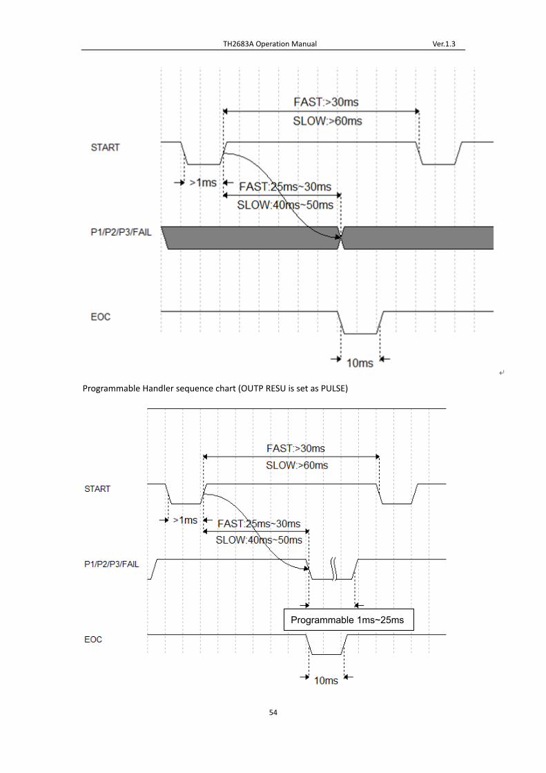
TH2683A Operation Manual Ver.1.3
54
Programmable Handler sequence chart (OUTP RESU is set as PULSE)
Programmable 1ms~25ms
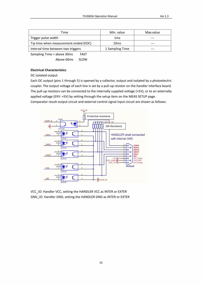
TH2683A Operation Manual Ver.1.3
55
Time Min. value Max.value
Trigger pulse width 1ms ‐‐‐
Tip time when measurement ended (EOC) 10ms ‐‐‐
Interval time between two triggers 1 Sampling Time ‐‐‐
Sampling Time = above 30ms FAST
Above 60ms SLOW
Electrical Characteristics
DC isolated output
Each DC output (pins 1 through 5) is opened by a collector, output and isolated by a photoelectric
coupler. The output voltage of each line is set by a pull‐up resistor on the handler interface board.
The pull‐up resistors can be connected to the internally supplied voltage (+5V), or to an externally
applied voltage (EXV: +5V) by setting through the setup item on the MEAS SETUP page.
Comparator result output circuit and external control signal input circuit are shown as follows:
VCC_IO: Handler VCC, setting the HANDLER VCC as INTER or EXTER
GND_IO: Handler GND, setting the HANDLER GND as INTER or EXTER

TH2683A Operation Manual Ver.1.3
56
9) Package Contents and Warranty
9.1 Package Contents
Following items should be contained in the package.
Verify that you have received all above items and any optional accessories you may have ordered.
If anyone is missing, please contact our company or operating division without delay.
NOTE: foot switch is optional component and it is sold separately.
9.2 Marks
The following marks can be seen on each instrument panel and nameplate:
a. Manufacturer name and trademark
b. Product name and model
c. Product number and date
d. the License for Manufacturing Measurement Instruments and its number
e. Marks for test terminal
9.3 Package
The instrument, generally wrapped in a plastic bag, should be packed in a strong packing box that
could resist dust, vibration and moisture. Accessories, spare parts, operation manual and
SSSeeerrr iiiaaalll
NNNuuummmbbbeeerrr
NNNaaammmeee QQQuuuaaannnttt iii tttyyy
1 TH2683A series instrument 1
2 Test cable (TH26004B) 1
3 Three‐Wire power line 1
4 Fuse (1A/2A) 1 of each
5 Operation Manual 1
6 Manufacturer Certificate 1
7 Test Report 1
8 Warranty Card 1

TH2683A Operation Manual Ver.1.3
57
manufacturer certificates, etc. should also be included in it.
9.4 Shipping
In the shipment, the instrument should be handled with care and some precautions must be
taken to resist moisture and water.
9.5 Storage
The instrument should be stored in an airy room where the environment temperature ranges
from 5℃ to 40℃, relative humidity is not greater than 85% and the air contains no detrimental
impurities that might corrode the instrument.
9.6 Warranty
This Tonghui instrument product is warranted against defects in material and workmanship for a
period of two years from the date of shipment. You should supply us with the warranty card
before you enjoy the free maintenance service. This warranty does not apply in the event of
misuse or abuse of the product or as a result of unauthorized alterations or repairs. Tonghui will,
without charge, repair or replace, at its option, defective product or component parts.
The maintenance for this instrument should be performed by professional maintenance
personnel. Do not substitute the internal components unauthorized when maintaining. In order
to ensure the measurement accuracy, the instrument must be measured and corrected after
maintenance. You should bear the maintenance expense for damages caused by unauthorized
repairing or substituting components.


![User's Model MY40 Insulation Resistance Tester [ …Insulation Resistance Tester [ Operation Manual ] This manual describes the specifications and handling precautions of the insulation](https://static.fdocuments.us/doc/165x107/5e58e655eb65b66d2954e0fb/users-model-my40-insulation-resistance-tester-insulation-resistance-tester-.jpg)