TFT LCD MONITOR - Vita Electronics CO., · PDF file · 2013-11-22TFT LCD MONITOR...
23
TFT LCD MONITOR VT-650YMN2 USER’S MANUAL V0.A
Transcript of TFT LCD MONITOR - Vita Electronics CO., · PDF file · 2013-11-22TFT LCD MONITOR...

TFT LCD MONITOR
VT-650YMN2
USER’S MANUAL V0.A
1
CONTENTS 1. Introduction Page 2
Product Description ....................................................... Page 2
Package Contents .......................................................... Page 2
Product Features …....................................................... Page 2
Screen Cleaning Techniques ......................................... Page 3
Additional ..................................................................... Page 3
2. Control Functions Page 5
Function Selection ......................................................... Page 5
Function Adjustments..................................................... Page 5
3. Installation ..................................................................... Page 15
4. Display Modes................................................................ Page 15
5. Signal Connector Pin-Outs........................................... Page 16
6. Power Saving Features................................................... Page 17
7. Product Specifications.................................................... Page 18
8. Windows Setup ............................................................. Page 19
9. Trouble Shooting …………………………………….. Page 20
2
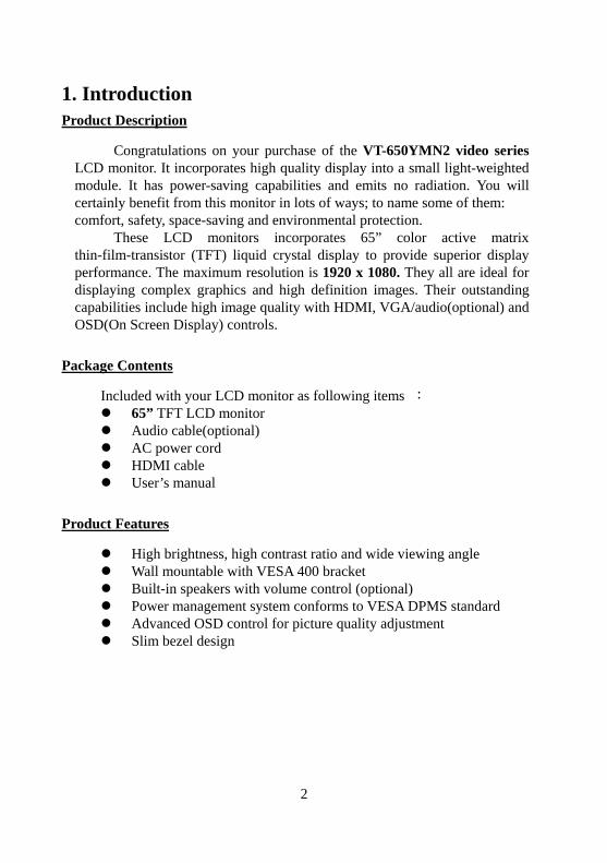
1. Introduction Product Description
Congratulations on your purchase of the VT-650YMN2 video series LCD monitor. It incorporates high quality display into a small light-weighted module. It has power-saving capabilities and emits no radiation. You will certainly benefit from this monitor in lots of ways; to name some of them: comfort, safety, space-saving and environmental protection.
These LCD monitors incorporates 65” color active matrix thin-film-transistor (TFT) liquid crystal display to provide superior display performance. The maximum resolution is 1920 x 1080. They all are ideal for displaying complex graphics and high definition images. Their outstanding capabilities include high image quality with HDMI, VGA/audio(optional) and OSD(On Screen Display) controls.
Package Contents
Included with your LCD monitor as following items : 65” TFT LCD monitor Audio cable(optional) AC power cord HDMI cable User’s manual
Product Features
High brightness, high contrast ratio and wide viewing angle Wall mountable with VESA 400 bracket Built-in speakers with volume control (optional) Power management system conforms to VESA DPMS standard Advanced OSD control for picture quality adjustment Slim bezel design
3
Screen Cleaning Techniques 1. Gently clean the screen with a clean camel hair lens brush, or a soft, clean,
lint-free cloth, to remove dust and other particles that can scratch the screen.
2. Do not apply pressure to the screen surface when wiping it clean. 3. Do not pour or spray any liquid directly onto the screen or casing. Chemical
cleaners have been reported to damage the screen or case of the LCD monitor.
Additional
Read all of these instructions and save them for later use. Follow all warnings and instructions on the product. 1. Product
Do not block the vent holes in the case. Do not insert sharp objects or spill liquid into the LCD monitor
through cabinet slots. They may cause accident fire, electric shock or failure.
Disconnect the power plug from the AC outlet if you will not use it for an extended period of time.
Do not attempt to service this product yourself, as opening or removing covers may expose you to dangerous voltage points or other risks.
Do not touch the screen directly with your fingers. You may damage the screen, and oil from your skin is difficult to remove.
Do not apply pressure to screen. The LCD panel is very delicate. 2. Power
Use the type of power indicated on label. 3. Plugs
Do not remove any of the prongs of the monitor’s three-pronged power plug.
Disconnect the power plug from the AC outlet under following conditions: If you will not use it for an extended period time. When the power cord or plug is damaged or frayed.

4
If the product does not operate normally when the operating
instructions are followed. Adjust only those controls that are covered by the operating instructions. Improper adjustment of other controls may result in damage and will often require extensive work by a qualified technician.
If the product exhibits a distinct change in performance,
service may be required. 4. Power and extension cords
Do not allow anything to rest on the power cord. Do not locate this product where persons will walk over the cord. Use the proper power cord with correct attachment plug type. If the
power source is 120V AC, use a power cord that has UL and C-UL approvals. If the power source is a 240V AC supply, use the tandem (T blade) type attachment plug with ground conductor power cord that meets the respective European country’s safety regulations, such as VDE for Germany.
Do not over load wall outlets or power cords. Ensure that the total of all units plugged into the wall outlet does not exceed 10 amperes.
Ensure that the total ampere ratings on all units plugged into the extension cord is not above the cord’s rating.
5. Environment
Place the monitor on a flat and leveled surface. Place the monitor in a well-ventilated place. Keep the monitor away from overly hot, cold or humid places, places
directly under sunlight, dusty surroundings, equipment that generate strong magnetic fields.
Please adjust the frequency to 60 Hz after setting up the LCD monitor. Then push the OSD menu button and use the auto adjustment function to
find the best mode of your computer.

5
2. Control Functions The monitor digital control functions are located on the rear panel. They are
shown in the figure below and described in the following paragraphs.
Function Selection
1. Press the knob “MENU/SELECT” to show the OSD menu. Then use the “ ” and “ ”△ ▽ to select a function. Press the knob “AUTO/EXIT” to close the OSD menu.
2. With the knob “ ” and “ ” , you can adjust the speaker volume△ ▽ on the monitor. When you press the “ ”▽ , the speakers are mute. Press the “ ”△ and
then the speakers are active. When you press the knob “ ”△ , the speaker volume OSD is shown.
You can increase or decrease the volume by pressing the “ ” and △
“ ”▽ . 3. You can hold the knob “AUTO/EXIT” for more than 1 second to adjust the
image quality automatically. The OSD menu will close automatically after 3-10 seconds without operation and saves any changes you have made. Function Adjustments
1. Signal Select
When there is no OSD menu display the knob “AUTO/EXIT” can select
HDMI / VGA(optional)
6
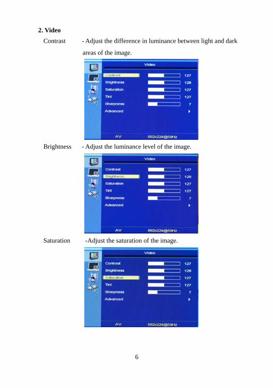
2. Video
Contrast - Adjust the difference in luminance between light and dark
areas of the image.
Brightness - Adjust the luminance level of the image.
Saturation -Adjust the saturation of the image.
7
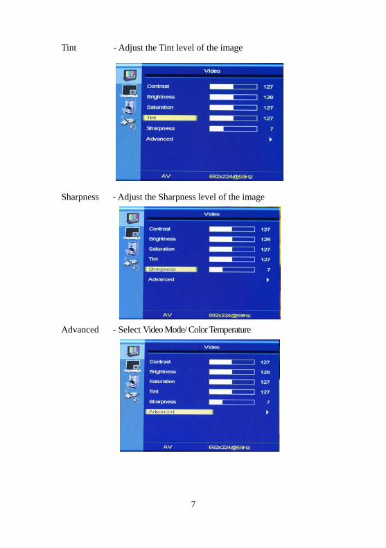
Tint - Adjust the Tint level of the image
Sharpness - Adjust the Sharpness level of the image
Advanced - Select Video Mode/ Color Temperature

8
Video Mode - Adjust the Video Mode for
Normal/Nature/Cinema/Sport/Vivid
Color Temperature - Adjust Color Temperature
Cool(9300k)/User/Warm(6500k)/Nature(7500k)
VGA
Contrast - Adjust the difference in luminance between light and dark
areas of the image.
9
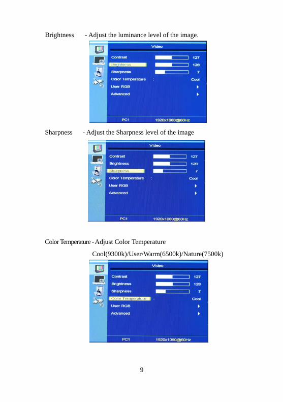
Brightness - Adjust the luminance level of the image.
Sharpness - Adjust the Sharpness level of the image
Color Temperature - Adjust Color Temperature
Cool(9300k)/User/Warm(6500k)/Nature(7500k)

10
User RGB - Adjusting R/G/B level of the image
Advanced -Select Auto Adjustment / Color Temperature
Auto Adjustment - Adjust geometry of the image automatically.

11
H Position - Adjust the horizontal position of the image.
V Position -Adjust the vertical position of image.
Clocks - Adjust the horizontal sync size of signal.

12
Phase - Adjust the horizontal sync phase of signal.
3. Display (Video & VGA)(optional)
Aspect Ratio - Adjust Aspect Ratio Full Screen/Cinma Scope/4:3/Pillar Box Expand/1:1
4. Audio (Video & VGA)(optional)
Volume - Adjust the speaker volume.

13
5. System Settings (Video & VGA)
Language -Select Language English/Trad.Chinese/Fran/Deu/Ita
OSD Timer - Adjust OSD Timer
OSD Transparency - Adjust OSD Transparency

14
Recall - Recall Factory setting
Key Lock -Set the function keys locked.
AP ID -Set the AP number of this monitor.
15
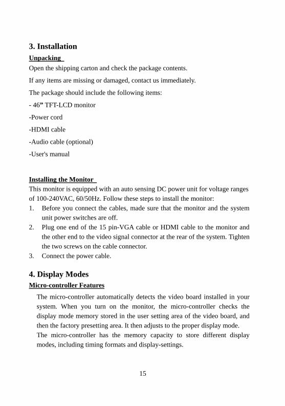
3. Installation Unpacking Open the shipping carton and check the package contents.
If any items are missing or damaged, contact us immediately.
The package should include the following items:
- 46” TFT-LCD monitor
-Power cord
-HDMI cable
-Audio cable (optional)
-User's manual
Installing the Monitor This monitor is equipped with an auto sensing DC power unit for voltage ranges of 100-240VAC, 60/50Hz. Follow these steps to install the monitor: 1. Before you connect the cables, made sure that the monitor and the system
unit power switches are off. 2. Plug one end of the 15 pin-VGA cable or HDMI cable to the monitor and
the other end to the video signal connector at the rear of the system. Tighten the two screws on the cable connector.
3. Connect the power cable. 4. Display Modes Micro-controller Features
The micro-controller automatically detects the video board installed in your system. When you turn on the monitor, the micro-controller checks the display mode memory stored in the user setting area of the video board, and then the factory presetting area. It then adjusts to the proper display mode. The micro-controller has the memory capacity to store different display modes, including timing formats and display-settings.

16
Factory Presetting Area
There are some preferred display modes preset in the micro-controller. These display modes are preset at the factory and include the most popular display modes currently available. The micro-controller searches for a proper display mode in this area if it fails to find a proper display mode in the user setting area.
MODE Resolution
(Dots*lines)
Horizontal
Freq.(KHz)
Vertical
Freq.(Hz)
Remark
1. VGA 640×350 31.5 70 Non-interlaced
2. VGA 720×400 31.5 70 Non-interlaced
3. VGA 640×480 31.5 60 Non-interlaced
4. VESA/75 640×480 37.5 75 Non-interlaced
5. VESA/60 800×600 37.9 60 Non-interlaced
6. VESA/75 800×600 46.9 75 Non-interlaced
7. VESA/60 1024×768 48.4 60 Non-interlaced
8. VESA/70 1024×768 56.5 70 Non-interlaced
9. VESA/75 1024×768 60.0 75 Non-interlaced
10. VESA/60 1280×1024 64.0 60 Non-interlaced
11. VESA/75 1280×1024 80.0 75 Non-interlaced
12. -- 1360×768 47.7 60 Non-interlaced
13. -- 1680×1050 65.3 60 Non-interlaced
14. -- 1920×1080 67.5 60 Non-interlaced
5. Signal Connector Pin-outs To connect VGA, 8514A or IBM-compatible graphics adapters, use a 15 pin mini D-type male connector.(optional)
17
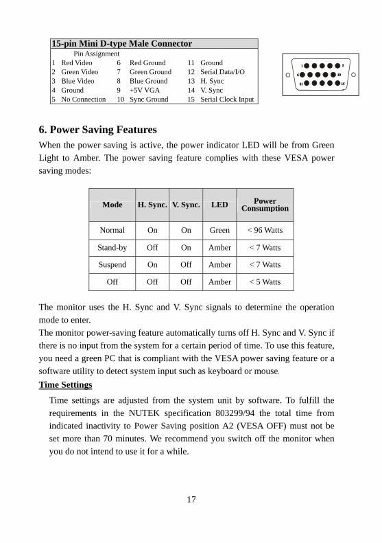
6. Power Saving Features When the power saving is active, the power indicator LED will be from Green Light to Amber. The power saving feature complies with these VESA power saving modes:
Mode H. Sync. V. Sync. LED Power Consumption
Normal On On Green < 96 Watts
Stand-by Off On Amber < 7 Watts
Suspend On Off Amber < 7 Watts
Off Off Off Amber < 5 Watts
The monitor uses the H. Sync and V. Sync signals to determine the operation mode to enter. The monitor power-saving feature automatically turns off H. Sync and V. Sync if there is no input from the system for a certain period of time. To use this feature, you need a green PC that is compliant with the VESA power saving feature or a software utility to detect system input such as keyboard or mouse.
Time Settings
Time settings are adjusted from the system unit by software. To fulfill the requirements in the NUTEK specification 803299/94 the total time from indicated inactivity to Power Saving position A2 (VESA OFF) must not be set more than 70 minutes. We recommend you switch off the monitor when you do not intend to use it for a while.
15-pin Mini D-type Male ConnectorPin Assignment
1 Red Video 6 Red Ground 11 Ground 2 Green Video 7 Green Ground 12 Serial Data/I/O 3 Blue Video 8 Blue Ground 13 H. Sync 4 Ground 9 +5V VGA 14 V. Sync 5 No Connection 10 Sync Ground 15 Serial Clock Input

18
7. Product Specifications
VT-650YMN2
Panel Type: Screen Size: Pixel Pitch: Brightness: Contrast Ratio: Response Time: Viewing Angle(H / V) Max. Resolution: Display Color
Active TFT-LCD 64.5” diagonal 0.744 mm Typical: 700 cd/㎡ Typical: 2500:1 Typical: 8ms (typ. G to G) Typical: 178° / 178°
1920 x 1080 1073.7 M
Video Input Analog: 15-pin, D-sub connector(optional) Digital: HDMI connector
Display Area 1428.5 (W) x 804.5 (H) mm
Input voltage 100-240V AC
Power Consumption TBD
Frequency Horizontal:30-80 KHz; Vertical: 50-60 Hz
Dimensions(W/I carton) TBD
Weight N.W.: TBD
G.W.: TBD
Operating Conditions 5°C – 40°C; 20%-80% RH
Storage Conditions: -10°C – 60°C; 10%-90% RH
Wall mountable VESA 400 bracket
The typical value of brightness, contrast ratio, response time and viewing angle is subject to change
without notice.
ModelFeatures
19
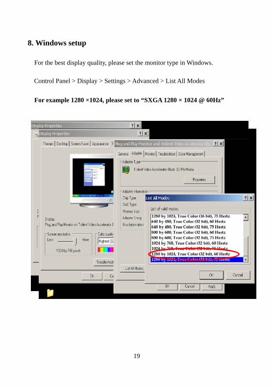
8. Windows setup For the best display quality, please set the monitor type in Windows.
Control Panel > Display > Settings > Advanced > List All Modes For example 1280 ×1024, please set to “SXGA 1280 × 1024 @ 60Hz”

20
9. Trouble Shooting
1) Power on but no picture
→ Make sure the VGA cable is tightly connected from the video output
connector on the video card to the video input connector on the monitor.
→ Make sure you are using the standard power adapter coming with the
monitor.
→ Check your video card if the driver is correctly installed. If there is no video
signal from the video card, “NO INPUT SIGNAL” will show on the screen.
2) Wrong or abnormal colors
→ If any color (red, green, or blue) is missing, check video cable to make sure
it is securely connected. Loose pins in the cable connector can cause a bad
connection.
3) The text and icon look blurry
→ LCD monitor has a native resolution which pixels are produced by cells in
fixed positions. When a resolution different from the native resolution is
chosen, the LCD monitor uses various interpolation methods to achieve the
pseudo resolution. To achieve the optimum viewing quality, choose the native
resolution of the panel is recommended.
→ Use “Auto Tuning” function to adjust image quality on the OSD menu or
you can hold button AUTO for 1 seconds to do auto tuning.
4) Display position is incorrect
→ Use “Auto Tuning” function to adjust image position on the OSD menu or
you can hold button AUTO for1 seconds to do auto tuning.
5) Speakers have no sound
→ Make sure the audio cable is tightly connected from the audio output jack on
the PC to the audio input jack on the monitor.
21
6) Residue image
→ If an image remains on the screen for an extended period of time, it may be
imprinted in the screen and leave a residue image. It is characteristic of liquid
crystal and is not malfunction or deterioration of the liquid crystal. The residue
image will disappear after a period of time. It is recommended to set up the
screen saver for your LCD monitor.
7) Out of Rang → The first thing you need to check is the screen resolution. Usually “Out of Range” is caused by improper resolution setting. You can recover the proper screen resolution as the following steps for Windows: (Assumed that the optimal resolution and frequency setting is 1280x1024@ 60Hz.) Boot the computer into VGA Mode (F8) [repeatedly] at startup. Go to “Control Panel”, double click on “Display”, click on the SETTINGS TAB, and click on the ADVANCED button. Then Click on the Adapter TAB, click “List All Modes” and change the screen resolution to 1280x1024. (You can select 16 bit or 32 bit color which depends on your video card capability.) Select “1280 by 1024, High Color (16 bit), Default Refresh” Click on the “OK” and “APPLY”. After clicking the APPLY button, a message will be displayed “Your desktop has been reconfigured. Do you want to keep these settings?” Click “Yes” and “OK”. Then click “OK” on the Display Properties window. Restart your PC After you restart, go back to “List All Modes” to adjust your screen refresh rate to 60 Hertz.

22
The “Out of Range” may happen if you switch monitor A to monitor B for your PC. Whenever you change the monitor for your PC, your PC may detect it as a new hardware and automatically install a proper driver for the monitor. So, you will have both monitor A and monitor B drivers on your PC. Sometimes the two monitor drivers may conflict each other and cause “Out of Range”. You can resolve “Out of Range” by uninstalling both monitor drivers and reboot your PC. The Windows will automatically detect the new hardware and install a proper driver for the monitor. Here is a quick way to uninstall the monitor drivers: Right click on “My Computer”, select “Properties” and click on “Hardware”. Click on “Device Manager”, select “Monitor” and click on “+” in front of “Monitor”. Then you can see one of the monitor drivers called “Plug and Play Monitor”. A quick way is to uninstall all the monitor drivers and then let Windows automatically detect the new hardware. (Right click on the monitor driver and select “Uninstall”). Restart your PC