Texture Spray Gun · 2020-03-29 · 3A3373C EN Operation, Parts Texture Spray Gun For water-Based...
18
3A3373C EN Operation, Parts Texture Spray Gun For water-Based Materials Only. Model: 24S134, 24S135, 24S155 non-bleeder, use with RTX Texture Sprayers 125 psi (8.6 bar, 0.86 MPa) Maximum Air/Fluid Working Pressure Model: 248093 bleeder, use with GTX Texture Sprayers 125 psi (8.6 bar, 0.86 MPa) Maximum Air/Fluid Working Pressure Important Safety Instructions Read all warnings and instructions in this manual and related manuals. Be familiar with the controls and the proper usage of the equipment. Save these instructions. ti28084a Use only genuine Graco replacement parts. The use of non-Graco replacement parts may void warranty. www.graco.com/techsupport ?? ??
Transcript of Texture Spray Gun · 2020-03-29 · 3A3373C EN Operation, Parts Texture Spray Gun For water-Based...

3A3373CEN
Operation, Parts
Texture Spray GunFor water-Based Materials Only.Model: 24S134, 24S135, 24S155 non-bleeder, use with RTX Texture Sprayers125 psi (8.6 bar, 0.86 MPa) Maximum Air/Fluid Working Pressure
Model: 248093 bleeder, use with GTX Texture Sprayers125 psi (8.6 bar, 0.86 MPa) Maximum Air/Fluid Working Pressure
Important Safety InstructionsRead all warnings and instructions in this manual and related manuals. Be familiar with the controls and the proper usage of the equipment. Save these instructions.
ti28084a
Use only genuine Graco replacement parts. The use of non-Graco replacement parts may void warranty.
www.graco.com/techsupport
?? ??

Contents
2 3A3373C
ContentsWarnings . . . . . . . . . . . . . . . . . . . . . . . . . . . . . . . . . . . . . . . . . . . . . . . . . . . . . . . . . . . . . 3
Component Identification . . . . . . . . . . . . . . . . . . . . . . . . . . . . . . . . . . . . . . . . . . . . . . . . 524S134, 24S135, 24S155, 248093 . . . . . . . . . . . . . . . . . . . . . . . . . . . . . . . . . . . . . . 5
Setup . . . . . . . . . . . . . . . . . . . . . . . . . . . . . . . . . . . . . . . . . . . . . . . . . . . . . . . . . . . . . . . . 6Pressure Relief Procedure . . . . . . . . . . . . . . . . . . . . . . . . . . . . . . . . . . . . . . . . . . . . . 6Spray Disc and Nozzle Selection . . . . . . . . . . . . . . . . . . . . . . . . . . . . . . . . . . . . . . . . 7
Gun Adjustments . . . . . . . . . . . . . . . . . . . . . . . . . . . . . . . . . . . . . . . . . . . . . . . . . . . . . . 8Shutdown and Cleanup . . . . . . . . . . . . . . . . . . . . . . . . . . . . . . . . . . . . . . . . . . . . . . . . . 9Repair . . . . . . . . . . . . . . . . . . . . . . . . . . . . . . . . . . . . . . . . . . . . . . . . . . . . . . . . . . . . . . . 10
Fluid Seal Replacement . . . . . . . . . . . . . . . . . . . . . . . . . . . . . . . . . . . . . . . . . . . . . . 10Air Seal Replacement . . . . . . . . . . . . . . . . . . . . . . . . . . . . . . . . . . . . . . . . . . . . . . . 11
Troubleshooting . . . . . . . . . . . . . . . . . . . . . . . . . . . . . . . . . . . . . . . . . . . . . . . . . . . . . . 1224S134, 24S135, 24S155, 248093 Gun Parts . . . . . . . . . . . . . . . . . . . . . . . . . . . . . . . . 14
Replacement WideTex Discs . . . . . . . . . . . . . . . . . . . . . . . . . . . . . . . . . . . . . . . . . . 1424S134, 24S135, 24S155, 248093 Gun Parts List . . . . . . . . . . . . . . . . . . . . . . . . . 15
Technical Specifications . . . . . . . . . . . . . . . . . . . . . . . . . . . . . . . . . . . . . . . . . . . . . . . 16Graco Standard Warranty . . . . . . . . . . . . . . . . . . . . . . . . . . . . . . . . . . . . . . . . . . . . . . 17Graco Information . . . . . . . . . . . . . . . . . . . . . . . . . . . . . . . . . . . . . . . . . . . . . . . . . . . . . 18

Warnings
3A3373C 3
WarningsThe following warnings are for the setup, use, grounding, maintenance, and repair of this equipment. The exclamation point symbol alerts you to a general warning and the hazard symbols refer to procedure-specific risks. When these symbols appear in the body of this manual or on warning labels, refer back to these Warnings. Product-specific hazard symbols and warnings not covered in this section may appear throughout the body of this manual where applicable.
EQUIPMENT MISUSE HAZARDMisuse can cause death or serious injury.• Always wear appropriate gloves, eye protection, and a respirator or mask when
painting.• Do not operate or spray near children. Keep children away from equipment at all
times.• Do not overreach or stand on an unstable support. Keep effective footing and
balance at all times.• Stay alert and watch what you are doing.• Do not operate the unit when fatigued or under the influence of drugs or alcohol.• Do not kink or over-bend the hose.• Do not expose the hose to temperatures or to pressures in excess of those
specified by Graco.• Do not use the hose as a strength member to pull or lift the equipment.• Do not alter or modify equipment. Alterations or modifications may void agency
approvals and create safety hazards.• Make sure all equipment is rated and approved for the environment in which you
are using it.

Warnings
4 3A3373C
SKIN INJECTION HAZARDHigh-pressure fluid from dispensing device, hose leaks, or ruptured compo-nents will pierce skin. This may look like just a cut, but it is a serious injury that can result in amputation. Get immediate surgical treatment.• Engage trigger lock when not dispensing.• Do not point dispensing device at anyone or at any part of the body.• Do not put your hand over the fluid outlet.• Do not stop or deflect leaks with your hand, body, glove, or rag.• Follow the Pressure Relief Procedure when you stop dispensing and
before cleaning, checking, or servicing equipment. • Tighten all fluid connections before operating the equipment.• Check hoses and couplings daily. Replace worn or damaged parts
immediately.PLASTIC PARTS CLEANING SOLVENT HAZARD Many solvents can degrade plastic parts and cause them to fail, which could cause serious injury or property damage. • Use only compatible water-based solvents to clean plastic structural or
pressure-containing parts.• See Technical Data in this and all other equipment instruction manuals. Read
fluid and solvent manufacturer’s Safety Data Sheet (SDS) and recommendations.
PERSONAL PROTECTIVE EQUIPMENTWear appropriate protective equipment when in the work area to help prevent serious injury, including eye injury, hearing loss, inhalation of toxic fumes, and burns. This protective equipment includes but is not limited to:• Protective eyewear, and hearing protection. • Respirators, protective clothing, and gloves as recommended by the fluid and
solvent manufacturer.CALIFORNIA PROPOSITION 65This product contains a chemical known to the State of California to cause cancer, birth defects or other reproductive harm. Wash hands after handling.

Component Identification
3A3373C 5
Component Identification24S134, 24S135, 24S155, 248093
24S134, interior gun kit includes WideTex™ discs24S135, exterior gun kit includes hardened WideTex discs24S155, gun only without WideTex discs248093, bleeder gun
A
B
D
E
F
H
C
ti28085a
A Air Control ValveB TriggerC Trigger LockD Retaining ring
E Prime ValveF Material InletH Nozzle
Setup
6 3A3373C
Setup
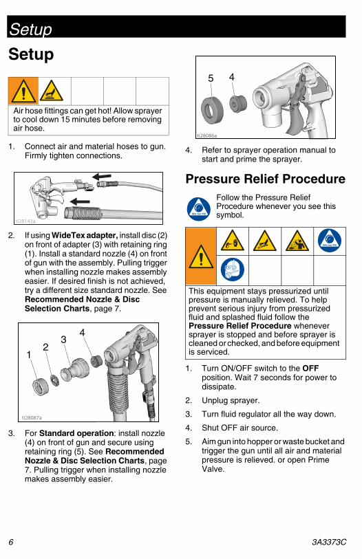
1. Connect air and material hoses to gun. Firmly tighten connections.
2. If using WideTex adapter, install disc (2) on front of adapter (3) with retaining ring (1). Install a standard nozzle (4) on front of gun with the assembly. Pulling trigger when installing nozzle makes assembly easier. If desired finish is not achieved, try a different size standard nozzle. See Recommended Nozzle & Disc Selection Charts, page 7.
3. For Standard operation: install nozzle (4) on front of gun and secure using retaining ring (5). See Recommended Nozzle & Disc Selection Charts, page 7. Pulling trigger when installing nozzle makes assembly easier.
4. Refer to sprayer operation manual to start and prime the sprayer.
Pressure Relief ProcedureFollow the Pressure Relief Procedure whenever you see this symbol.
1. Turn ON/OFF switch to the OFF position. Wait 7 seconds for power to dissipate.
2. Unplug sprayer.
3. Turn fluid regulator all the way down.
4. Shut OFF air source.
5. Aim gun into hopper or waste bucket and trigger the gun until all air and material pressure is relieved. or open Prime Valve.
Air hose fittings can get hot! Allow sprayer to cool down 15 minutes before removing air hose.
ti28143a
23
1
4
ti28087a
This equipment stays pressurized until pressure is manually relieved. To help prevent serious injury from pressurized fluid and splashed fluid follow the Pressure Relief Procedure whenever sprayer is stopped and before sprayer is cleaned or checked, and before equipment is serviced.
ti28086a
45
Setup
3A3373C 7
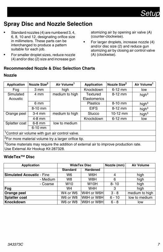
Spray Disc and Nozzle Selection• Standard nozzles (4) are numbered 3, 4,
6, 8, 10 and 12, designating orifice size in millimeters. These parts can be interchanged to produce a pattern suitable for each job.
• For smaller droplet sizes, reduce nozzle (4) and/or disc (2) size and increase gun
atomizing air by opening air valve (A) (counter-clockwise).
• For larger droplets, increase nozzle (4) and/or disc size (2) and reduce gun atomizing air by closing air control valve (A) (clockwise).
Recommended Nozzle & Disc Selection Charts
Nozzle
WideTex™ Disc
Application Nozzle Size2 Air Volume1 Application Nozzle Size2 Air Volume1
Fog 3 mm high Knockdown 6-12 mm lowSimulated Acoustic
4 mm medium to high Textured Elastomerics
8-12 mm high3
6 mm Plastics 8-10 mm high3
8-10 mm EIFS 8-12 mm high3
Orange peel 3-4 mm medium to high Stucco 10-12 mm high3
4-8 mm Knockdown 6-12 mm lowSplatter coat 6-8 mm low to medium
6-10 mm1Control air volume with gun air control valve.2For more material volume try a larger orifice tip.3Some materials may require the addition of external air to improve production rate. Use External Air Hookup Kit 287328.
Application WideTex Disc Nozzle (mm) Air VolumeStandard Hardened
Simulated Acoustic - Fine W6 W6H 4 high - Medium W8 W8H 6 high - Coarse W10 W10H 8- 10 high
Fog W4 W4H 3 highOrange peel W4 or W6 W4H or W6H 3 - 8 medium to highSplatter coat W6 or W8 W6H or W8H 6 - 10 low to mediumKnockdown W6 or W8 W6H or W8H 6 - 8 low

Gun Adjustments
8 3A3373C
Gun AdjustmentsSufficient fluid output (volume and pressure)and good atomization is a balance ofatomizing air, material thickness/materialflow and nozzle selection. Achieving thecorrect balance for your application requiresexperimentation to achieve desired results.Keep in mind these important points whenadjusting gun:
• To select correct nozzle for your applications, consider size of aggregate in material and coarseness of spray pattern. Remember the larger the nozzle, the larger the pattern. See Recommended Nozzle & Disc Selection Charts, page 7.
• Start sprayer with gun air control valve completely open. If needed, slowly close gun air control valve until you get a good spray pattern. Use minimum amount of air at spray gun to achieve proper spray pattern and to minimize bounce back.
+ Test spray pattern on cardboard. Hold gun 18 to 30 in. (45.7 to 76.2 cm) from surface. Use this spraying dis-tance for most applications.
+ When spraying with a nozzle only overlap each stroke 50% in a circular motion.
+ When spraying with a nozzle and disc overlap each stroke 50% in a linear motion.
• Material flow is controlled with the fluid flow regulator knob and displayed on the gauge. Gun air flow is regulated using air control valve located on the gun handle.
+ Opening air control valve increases air flow through gun, which decreases texture material flow through pump.
+ Closing air control valve decreases air flow through gun, which increases texture material flow through pump.
For Less Material FlowTry one or a combination of these methods:
• Open air control valve.
• Turn material flow control on sprayer to decrease flow, counter-clockwise.
• Use smaller nozzle.
For More Material FlowTry any one or a combination of thesemethods:
• Close air control valve.
• Turn material flow control on sprayer to increase flow.
• Use thinner material mixture.
• Use a larger nozzle.
Preventing Material Surge at Gun TriggerPressure will build up in the system when youstop triggering the gun. To prevent materialsurge at initial gun triggering:
• Point gun away from surface you are spraying when you first pull trigger.
• When you first start to spray, hold the gun away from the surface and gradually work your way closer to it.
• Keep gun moving.
• After you begin spraying, trigger the gun as little as possible.
For Continuous SprayingUse trigger lock to hold trigger open andreduce fatigue.
Check Material Consistency PeriodicallyCheck and thin material as needed tomaintain proper consistency. The materialmay thicken as it sits and slow downproduction. Agitate periodically.

Shutdown and Cleanup
3A3373C 9
Shutdown and Cleanup
NOTE: Keep pump and hose clean when switching between materials. A dirty pump can release particles of texture into the finish.
When you have finished spraying:
1. Drain remaining material into bucket until most of texture material is out of the hopper.
2. Fill material hopper with clean water.
3. Remove nozzle from gun. Trigger gun into bucket until most of texture mix is pumped out. Allow water to flow through gun until gun is clean.
4. Finish cleaning all components. A soft brush may be used to help loosen any dried on material from surface.
NOTE: Cleaning out all air passages and components will improve gun per-formance and life.
5. Connect air line to gun. Open gun air control valve, forcing air through nozzle to clear out any remaining material.
6. Disconnect air line and material hose from gun.
To ensure proper gun function for future use,remove and clean needle components andapply a few drops of light oil to:
• air hose quick connect
• material hose connections
• air shutoff needle material needle
NOTICE
Before removing material hose be sure pressure is relieved and material is not in the hose.
To keep sprayer in good operating condition, always clean it throughly and prepare it properly for storage.
ti28088a
ti28086a
45
ti28089a

Repair
10 3A3373C
RepairRepair involves the removal and replacementof worn or damaged parts.
Fluid Seal ReplacementFor Non-bleeder guns use Seal ReplacementKit, 287228. For bleeder guns use SealReplacement Kit, 287338.
1. Remove retaining ring (11), nozzle (28), and needle assembly (9) through front of gun.
2. Use a hook-shaped object to carefully pull up-cup retainer and u-cup out of gun.
3. Using your finger or a 1/2-in. diameter rod, push new seal (3) in place. Make sure seal is seated against sleeve bearing (35).
4. Insert u-cup retaining ring (41). Make sure retaining ring is seated against u-cup (3).
5. Graco recommends you replace the entire fluid needle assembly at this time, including the needle (9) spring (5), packing o-ring (6) and guide (7).
6. Trigger gun a few times to make sure u-cup and retainer are securely in place.
NOTICE
U-cup seals are very fragile. Never pound on seal when during assembly.
ti28090a
ti28091a
ti28091a
ti28094a

Repair
3A3373C 11
Air Seal Replacement(Use Seal Replacement Kit, 287229.)
1. Remove air valve retainer (21), compression spring (19), air valve seal (18) and needle (17) through back of gun.
2. Use a hook-shaped object to carefully pull u-cup seal (4) out of gun.
3. Push new seal (4) in place using a small diameter (1/4 in. or smaller) object. Make sure seal is seated against sleeve bearing (36).
4. Replace air valve needle (17) seal (18), spring (19) and O-ring (20) if necessary.
ti28093a
ti28095a
ti28096a

Troubleshooting
12 3A3373C
Troubleshooting
1. Follow , page 6, before checking or repairing.
2. Check all possible problems and causes before disassembling the unit.
Problem
What to CheckIf check is OK, go to next
check
What to DoWhen check is not OK,
refer to this column
Material will not flow out of gun
Material too thick Thin material. Increase pres-sure at pump.
Not enough air Open gun air control valve (A) more (counter-clockwise)
Trigger adjustment set too low
Rotate trigger nut clockwise to increase (adjust) trigger travel
Nozzle too small Increase nozzle size
Gun is plugged Clean gun
Pattern too fine Material too thin Add more dry material to mix to thicken
Air pressure too high Close gun air control valve (A) partially (clockwise)
Gun needle travel too low Rotate trigger nut clockwise to increase (adjust) trigger travel
Nozzle too small Replace nozzle with larger size
Pattern too coarse Material too thick Add water to mix to thin material
Air pressure too low Open gun air control valve (A) more (counter-clockwise)
Nozzle too large Replace nozzle with smaller size
Gun will not shut off Worn nozzle and/or needle Replace worn parts
Nozzle retaining ring not on all the way
Tighten completely.
Debris in gun passages Clean gun.
Fluid leaking at flow needle nut (8)
Damaged seal Replace seal (3).

Troubleshooting
3A3373C 13
Needle nut won’t adjust Dirty threads Clean threads.
Nozzle not on gun Put nozzle on gun.
Needle triggered Adjust when trigger is not pulled.
Air won’t shut off when gun trigger is released
Debris in gun air passages Clean gun.
Loose air fittings Tighten air fittings on gun
Worn air seals Replace air shutoff needle u-cup (4) and/or air valve seal (18)
Prime valve is leaking. Remove and clean prime valve.
Prime valve is plugged. Remove and clean prime valve.
Problem
What to CheckIf check is OK, go to next
check
What to DoWhen check is not OK,
refer to this column
24S134, 24S135, 24S155, 248093 Gun Parts
14 3A3373C
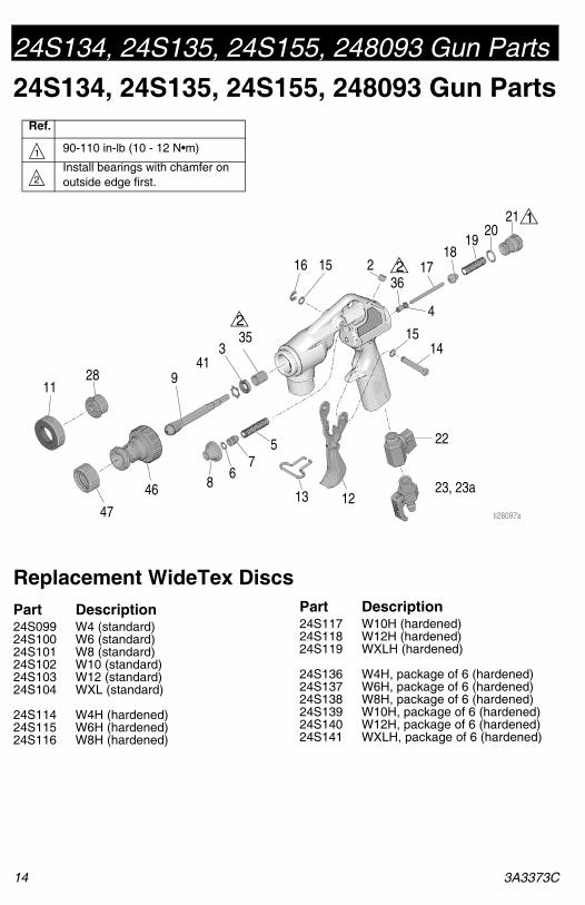
24S134, 24S135, 24S155, 248093 Gun Parts
Replacement WideTex Discs
Ref.
90-110 in-lb (10 - 12 N•m)
Install bearings with chamfer on outside edge first.
1
2
1128
47
46
941
335
86
75
13 1223, 23a
22
1415
16 15 236
4
1718
1920
21
ti28097a
2
1
2
Part Description24S099 W4 (standard)24S100 W6 (standard)24S101 W8 (standard)24S102 W10 (standard)24S103 W12 (standard)24S104 WXL (standard)
24S114 W4H (hardened)24S115 W6H (hardened)24S116 W8H (hardened)
24S117 W10H (hardened)24S118 W12H (hardened)24S119 WXLH (hardened)
24S136 W4H, package of 6 (hardened)24S137 W6H, package of 6 (hardened)24S138 W8H, package of 6 (hardened)24S139 W10H, package of 6 (hardened)24S140 W12H, package of 6 (hardened)24S141 WXLH, package of 6 (hardened)
Part Description
24S134, 24S135, 24S155, 248093 Gun Parts
3A3373C 15
24S134, 24S135, 24S155, 248093 Gun Parts ListRef. Part Description Qty.2 103147 PLUG, pipe, Guns
24S134, 24S135, 24S155
1
3 15D125 SEAL, u-cup,.375 dia. shaft
1
4 15D126 SEAL, u-cup, 156 dia. shaft, Guns 24S134, 24S135, 24S155
1
5 118592 SPRING, compression 16 156454 PACKING, o-ring 17 15C894 GUIDE, needle, fluid 18 15B163 NUT, needle 19 NEEDLE, fluid, assbly
246972 Guns 24S134, 24S135, 24S155
1
246971 Gun 248093 111 15B042 RING, retaining, nozzle 112 15C882 TRIGGER, gun 113 15D120 LOCK, trigger 114 118717 PIN, clevis w groove 115 107243 WASHER 216 115999 RING, retaining 117 15C895 NEEDLE, air valve, 156
dia. shaft, Guns 24S134, 24S135, 24S155
1
18 15D104 SEAL, air valve, 156 dia. shaft, Guns 24S134, 24S135, 24S155
1
19 108961 SPRING, compression, 156 dia. shaft, Guns 24S134, 24S135, 24S155
1
20 103610 PACKING, o-ring 121 15C896 RETAINER, spring, air
valve1
22 17H665 VALVE, ball 123 17J436 ASSEMBLY, prime
valve, 156 dia. shaft, Guns 24S134, 24S135, 24S155
1
23a 17K135 FITTING, air, line, Gun 248093
1
28 NOZZLE28a 15C883 NOZZLE, texture 3mm 128b 15C884 NOZZLE, texture 4 mm 128c 15C885 NOZZLE, texture 6 mm 128d 15C886 NOZZLE, texture 8 mm 128e 15C887 NOZZLE, texture 10 mm 128f 15C888 NOZZLE, texture 12 mm 135 119183 BEARING, sleeve, 0.375
dia. shaft1
36 119184 BEARING, sleeve, 4 mm dia. shaft, 156 dia. shaft, Guns 24S134, 24S135, 24S155
1
37 KIT, repair, fluid needle, includes 3, 5, 6, 7, 8, 9, 10, 16, 35
287228 Guns 24S134, 24S135, 24S155
1
287338 Gun 248093 138 287229 KIT, repair, air needle
includes 4, 17, 18, 19, 20, 36
1
39 LABEL, right17H679 Guns 24S134, 24S135,
24S1551
15D932 Gun 248093 140 LABEL, left
17H680 Guns 24S134, 24S135, 24S155
1
15D930 Gun 248093 141 119343 RING, retaining 146 17E200 HOUSING, adapter 147 17H637 RING, retaining 1
24S142 KIT, accessory, WideTex includes 46, 47, nozzles W4, W6, W8, W10, W12, WXL
1
24S143 KIT, accessory, WideTex includes 46, 47, nozzles W4H, W6H, W8H, W10H, W12H, WXLH
1
Ref. Part Description Qty.

Technical Specifications
16 3A3373C
Technical SpecificationsUS Metric
Spray GunMaximum Fluid Working Pressure
Non-bleeder gun 125 psi 8.6 bar, 0.9 MPaBleeder gun 125 psi 8.6 bar, 0.9 MPa
Maximum Air Working Pressure 125 psi 8.6 bar, 0.9 MPaAir Requirements (maximum) 30 scfm 0.84m3/minFluid Inlet Size 1 in. NPT 25.4 mmDimensionsHeight 10.3 in. 262 mmLength 7.5 in. 191 mmWidth 1.7 in. 43 mmWeight (dry) 2.3 lb. 1.0 kgNoise**
Sound Pressure Level 80.8 dBa*Sound Power Level 96.5 dBa*
Materials of ConstructionWetted materials on all models Anodized Aluminum, Stainless Steel, Buna-N, UHMW
Polyethylene, Brass, Steel, Viton, DelrinNotes* Spraying simulated acoustic at full air and maximum material pressure.** Sound pressure measured 3 feet (1 meter) from equipment while spraying. Sound power measured per ISO-9614.

Graco Standard Warranty
3A3373C 17
Graco Standard WarrantyGraco warrants all equipment referenced in this document which is manufactured by Graco and bearing its name to be free from defects in material and workmanship on the date of sale to the original purchaser for use. With the exception of any special, extended, or limited warranty published by Graco, Graco will, for a period of twelve months from the date of sale, repair or replace any part of the equipment determined by Graco to be defective. This warranty applies only when the equipment is installed, operated and maintained in accordance with Graco’s written recommendations.
This warranty does not cover, and Graco shall not be liable for general wear and tear, or any malfunction, damage or wear caused by faulty installation, misapplication, abrasion, corrosion, inadequate or improper maintenance, negligence, accident, tampering, or substitution of non-Graco component parts. Nor shall Graco be liable for malfunction, damage or wear caused by the incompatibility of Graco equipment with structures, accessories, equipment or materials not supplied by Graco, or the improper design, manufacture, installation, operation or maintenance of structures, accessories, equipment or materials not supplied by Graco.
This warranty is conditioned upon the prepaid return of the equipment claimed to be defective to an authorized Graco distributor for verification of the claimed defect. If the claimed defect is verified, Graco will repair or replace free of charge any defective parts. The equipment will be returned to the original purchaser transportation prepaid. If inspection of the equipment does not disclose any defect in material or workmanship, repairs will be made at a reasonable charge, which charges may include the costs of parts, labor, and transportation.
THIS WARRANTY IS EXCLUSIVE, AND IS IN LIEU OF ANY OTHER WARRANTIES, EXPRESS OR IMPLIED, INCLUDING BUT NOT LIMITED TO WARRANTY OF MERCHANTABILITY OR WARRANTY OF FITNESS FOR A PARTICULAR PURPOSE.
Graco’s sole obligation and buyer’s sole remedy for any breach of warranty shall be as set forth above. The buyer agrees that no other remedy (including, but not limited to, incidental or consequential damages for lost profits, lost sales, injury to person or property, or any other incidental or consequential loss) shall be available. Any action for breach of warranty must be brought within two (2) years of the date of sale.
GRACO MAKES NO WARRANTY, AND DISCLAIMS ALL IMPLIED WARRANTIES OF MERCHANTABILITY AND FITNESS FOR A PARTICULAR PURPOSE, IN CONNECTION WITH ACCESSORIES, EQUIPMENT, MATERIALS OR COMPONENTS SOLD BUT NOT MANUFACTURED BY GRACO. These items sold, but not manufactured by Graco (such as electric motors, switches, hose, etc.), are subject to the warranty, if any, of their manufacturer. Graco will provide purchaser with reasonable assistance in making any claim for breach of these warranties.
In no event will Graco be liable for indirect, incidental, special or consequential damages resulting from Graco supplying equipment hereunder, or the furnishing, performance, or use of any products or other goods sold hereto, whether due to a breach of contract, breach of warranty, the negligence of Graco, or otherwise.
FOR GRACO CANADA CUSTOMERSThe Parties acknowledge that they have required that the present document, as well as all documents, notices and legal proceedings entered into, given or instituted pursuant hereto or relating directly or indirectly hereto, be drawn up in English. Les parties reconnaissent avoir convenu que la rédaction du présente document sera en Anglais, ainsi que tous documents, avis et procédures judiciaires exécutés, donnés ou intentés, à la suite de ou en rapport, directement ou indirectement, avec les procédures concernées.

All written and visual data contained in this document reflects the latest product information available at the time of publication.
Graco reserves the right to make changes at any time without notice.
Original instructions. This manual contains English. MM 3A3373
Graco Headquarters: MinneapolisInternational Offices: Belgium, China, Japan, Korea
GRACO INC. AND SUBSIDIARIES • P.O. BOX 1441 • MINNEAPOLIS MN 55440-1441 • USACopyright 2016, Graco Inc. All Graco manufacturing locations are registered to ISO 9001.
www.graco.comRevision C, May 2019
Graco InformationFor the latest information about Graco products, visit www.graco.com.
For patent information, see www.graco.com/patents.
TO PLACE AN ORDER, contact your Graco distributor or call 1-800-690-2894 to identify the nearest distributor.


![GPG Gravity Spray Gun gpg.pdfThe GPG spray gun is a professional quality spray gun designed to comply with all global legislations. Trigger 12 bar [175 psi] ... Never use 1,1,1-Trichloroethane,](https://static.fdocuments.us/doc/165x107/610bfed5e0aa09342647c21f/gpg-gravity-spray-gun-gpgpdf-the-gpg-spray-gun-is-a-professional-quality-spray.jpg)