Texture and other Mappings - Carnegie Mellon School of Computer...
59
1 Computer Graphics 15-462 Texture and other Mappings Shadows Texture Mapping Bump Mapping Displacement Mapping Environment Mapping Shadows Texture Mapping Bump Mapping Displacement Mapping Environment Mapping Angel Chapter 7 COMPUTER GRAPHICS 15-462
Transcript of Texture and other Mappings - Carnegie Mellon School of Computer...

1Computer Graphics 15-462
Texture and other Mappings
ShadowsTexture MappingBump MappingDisplacement MappingEnvironment Mapping
ShadowsTexture MappingBump MappingDisplacement MappingEnvironment Mapping
Angel Chapter 7
COMPUTER GRAPHICS15-462

2Computer Graphics 15-462
Announcements• Written assignment #1 back later next week.

3Computer Graphics 15-462
ShadowsShadows occur where objects are hidden from a light source• Omit any intensity contribution from hidden light sources• Umbra and penumbra (function of size of light source)• Soft shadows and hard shadows (point light source at a distance)• Important perceptual clue for connecting objects to ground (feet in
particular)• But object-to-object shadows also important• In general, shadows from many light sources

4Computer Graphics 15-462
Planar Projection ShadowsSimplest case:Point light source (no penumbra) and shadows only on
the ground planeGood for flight simulators
Shadow is projection of polygononto the surface with the center of projection at the light source

5Computer Graphics 15-462
Planar Projection Shadows
Put light source at origin with
Simple perspectiveprojection through the
origin:
Translate back with
),,( 111 zyxT −−−
����
�
�
����
�
�
=
00/10
0100
0010
0001
1y
M
),,( 111 zyxT

6Computer Graphics 15-462
Planar Projection Shadows in OpenGL
GlFloat m[16]; /* shadow projection matrix */
For (i=0;i<15;i++) m[i]=0.0;
m[0] = m[5] =m[10] = 1.0; m[7] = -1.0/y1;
glBegin(GL_POLYGON);
/* draw the polygon normally */
glEnd();
glMatrixMode(GL_MODELVIEW);
glPushMatrix(); /* save state*/
glTranslatef(x1,y1,z1); /* translate back */
glMultMatrixf(m); /* project*/
glTranslate(-x1,-y1,-z1); /* move light to origin */
glColor3fv(shadow_color);
glBegin(GL_POLYGON);
/* draw the polygon again */
glEnd();
glPopMatrix(); /* restore state */

7Computer Graphics 15-462
Question• If a perspective transform does a point light
source, what does a directional light source?
• [Angel demo]
8Computer Graphics 15-462
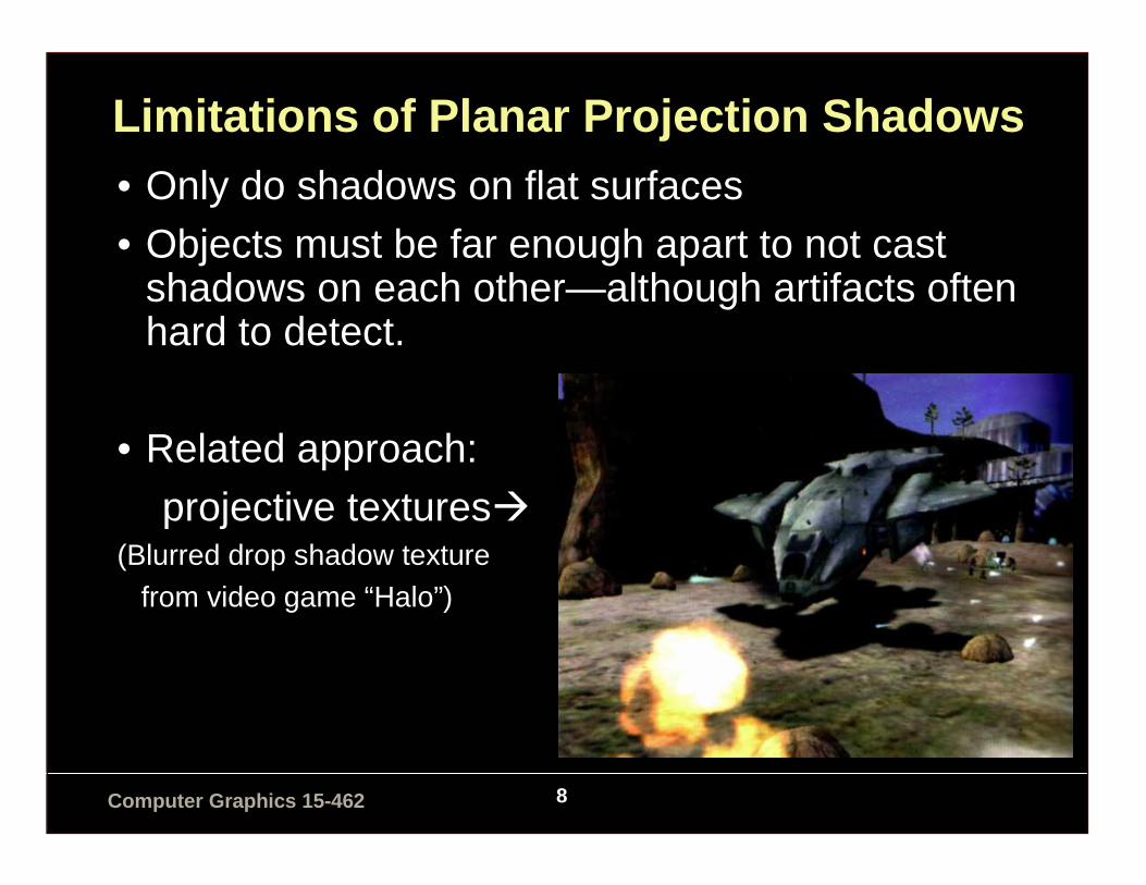
Limitations of Planar Projection Shadows• Only do shadows on flat surfaces• Objects must be far enough apart to not cast
shadows on each other—although artifacts often hard to detect.
• Related approach:
projective textures�(Blurred drop shadow texture
from video game “Halo”)

9Computer Graphics 15-462
Other Shadow Algorithms
Shadow Maps (Williams, 1978):
• Z-Buffer algorithm• Works for curved surfaces
1. Render from light source to compute depth map (z distance toclosest object for each pixel in the map).
2. While rendering, if a point (x,y,z) is visible, map (x,y,z) in the coordinates of the viewpoint to (x’,y’,z’), the coordinates of the point from the light.
3. If z’ is greater than the value in the z-buffer for that point, then a surface is nearer to the light source than the point under consideration and the point is in shadow. If so, render with a shadow intensity, if not render as normal.
• Handles multiple light sources (with multiple z-buffers), moving objects and lights (at the cost of several renderings). Clearly a winning strategy with hardware.

10Computer Graphics 15-462
Shadow Maps (Williams, 1978)
11Computer Graphics 15-462
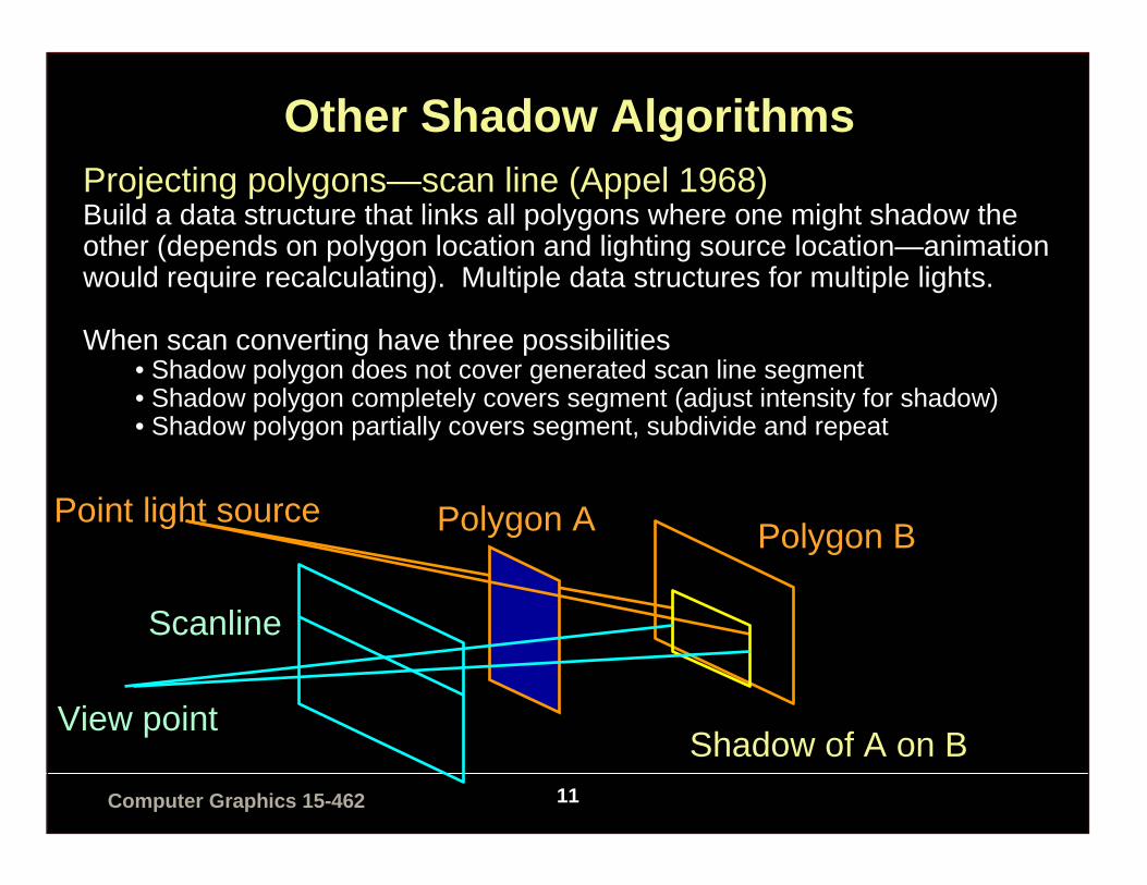
Other Shadow AlgorithmsProjecting polygons—scan line (Appel 1968)Build a data structure that links all polygons where one might shadow the other (depends on polygon location and lighting source location—animation would require recalculating). Multiple data structures for multiple lights.
When scan converting have three possibilities• Shadow polygon does not cover generated scan line segment• Shadow polygon completely covers segment (adjust intensity for shadow)• Shadow polygon partially covers segment, subdivide and repeat
Point light source Polygon A
Shadow of A on B
Polygon B
View point
Scanline

12Computer Graphics 15-462
Other Shadow AlgorithmsShadow Volumes (Crow 1977)Compute the volume of space swept out by an object, intersected with the viewing volume.
Include these invisible objects in rendering pipeline.Render visible objects as in shadow if they are in front of a back facing shadow polygon and in back of a front facing polygon. Extend the z buffer to contain this extra information.
View volume
Point light source Polygon
Intersection of shadow volume with view volume

13Computer Graphics 15-462
Examples: Shadow Volumes

14Computer Graphics 15-462
Texture Mapping

15Computer Graphics 15-462
• Real objects have small surface features• One option: use a huge number of polygons with
appropriate surface coloring and reflectance characteristics
• Another option: use a mapping algorithm to modify the shading algorithm
– Texture mapping– Bump mapping– Displacement mapping– Environmental mapping
Last time we talked about shading. But uniformly colored or shaded surfaces are unrealistic.
16Computer Graphics 15-462
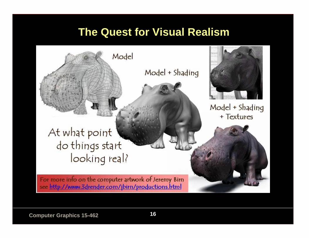
The Quest for Visual Realism
17Computer Graphics 15-462
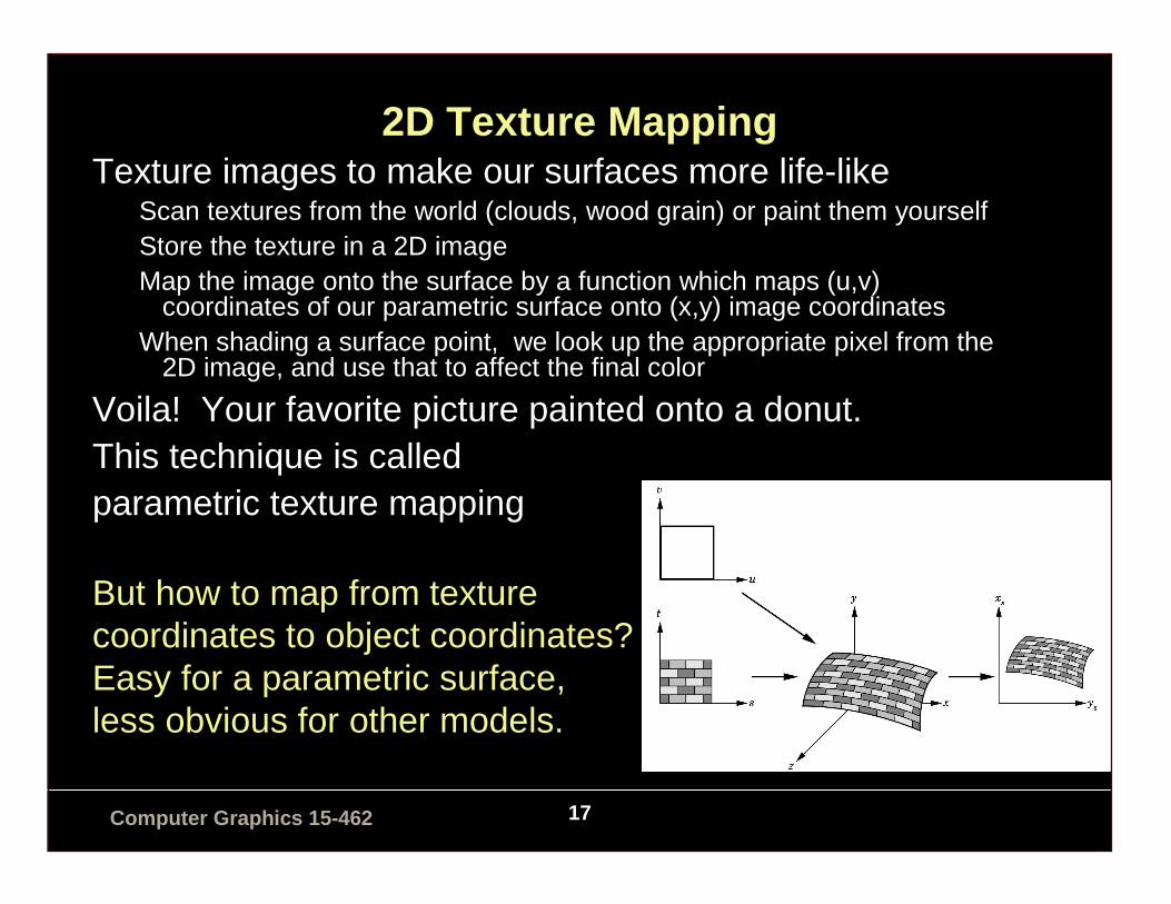
2D Texture MappingTexture images to make our surfaces more life-like
Scan textures from the world (clouds, wood grain) or paint them yourselfStore the texture in a 2D imageMap the image onto the surface by a function which maps (u,v)
coordinates of our parametric surface onto (x,y) image coordinatesWhen shading a surface point, we look up the appropriate pixel from the
2D image, and use that to affect the final color
Voila! Your favorite picture painted onto a donut.This technique is called parametric texture mapping
But how to map from texturecoordinates to object coordinates?Easy for a parametric surface,less obvious for other models.

18Computer Graphics 15-462
Texture Mapping: General
( )( )( )wvuT
vuT
uT
,,
, ( )ss yx ,( )www zyx ,,
Texture Space Object Space Screen Space

19Computer Graphics 15-462
Specifying the Mapping Function
Some objects have natural parameterizations:– Sphere: use spherical coordinates (φ,θ)=(2πu,πv)– Cylinder: use cylindrical coordinates (u,θ)=(u,2πv)

20Computer Graphics 15-462
Specifying the Mapping Function
Some objects have natural parameterizations:– Parametric surface (such as B-spline or Bezier): use patch
parameters (u,v)
)(
)(
minmaxminmax
minmin
minmaxminmax
minmin
vvtt
ttvv
uuss
ssuu
−−
−+=
−−
−+=
Doesn’t take into account the curvature of the surface: stretching.Just like with roller coaster.

21Computer Graphics 15-462
Specifying the Mapping Function
What about arbitrary polygonal objects?Two step mapping:• To a canonical shape first• Then project normals from object
a) From texture value to objectb) Use normals to find texturec) Line from center to point to
texture value

22Computer Graphics 15-462
Or design the mapping by hand

23Computer Graphics 15-462
Demo: “uvMapper”
• www.uvmapper.com

24Computer Graphics 15-462
Texture Mapping in OpenGL
A parallel pipeline for pixel operations:Texture mapping is part of the shading process

25Computer Graphics 15-462
Texture Mapping in OpenGL
Glubyte my_texels[512][512];glTexImage2D(GL_TEXTURE_2D, 0, 3, 512, 512, 0,
GL_RGB,GL_UNSIGNED_BYTE, my_texels);/* level, components, w, h, border, format, type, tarray */
glEnable(GL_TEXTURE_2D);
/* assign texture coordinates */glBegin(GL_QUAD);
glTexCoord2f(0.0, 0.0);glVertex2f(x1,y1,z1);glTexCoord2f(1.0, 0.0);glVertex2f(x2,y2,z2);glTexCoord2f(1.0,1.0);glVertex2f(x3,y3,z3);glTexCoord2f(0.0,1.0);glVertex2f(x4,y4,z4);
glEnd();
26Computer Graphics 15-462
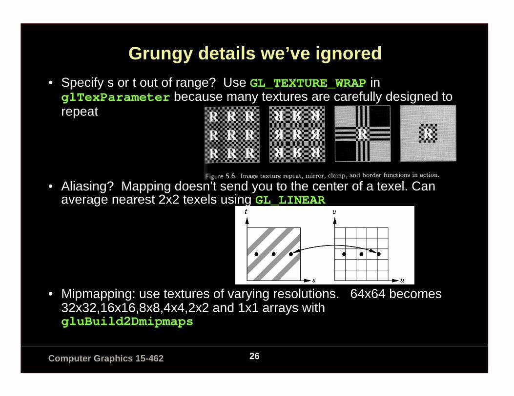
Grungy details we’ve ignored
• Specify s or t out of range? Use GL_TEXTURE_WRAP in glTexParameter because many textures are carefully designed to repeat
• Aliasing? Mapping doesn’t send you to the center of a texel. Can average nearest 2x2 texels using GL_LINEAR
• Mipmapping: use textures of varying resolutions. 64x64 becomes 32x32,16x16,8x8,4x4,2x2 and 1x1 arrays with gluBuild2Dmipmaps

27Computer Graphics 15-462
What is aliasing?
• Sampling error when mapping texture images to screen

28Computer Graphics 15-462
What is aliasing?
• An on-screen pixel may not map neatly to a texel.

29Computer Graphics 15-462
Example: Checkerboard
• Particularly severe problems in regular textures

30Computer Graphics 15-462
The Beginnings of a Solution: Mipmapping
• Pre-calculate how the texture should look at various distances, thenuse the appropriate texture at each distance. This is called mipmapping.
• “Mip” � “multum in parvo” or “many things in a small place”• Each mipmap (each image below) represents a level of resolution.• Powers of 2 make things much easier.

31Computer Graphics 15-462
The Beginnings of a Solution
• Problem: Clear divisions between different depth levels• Mipmapping alone is unsatisfactory.

32Computer Graphics 15-462
Another Component: Filtering
• Take the average of multiple texels to obtain the final RGB value
• Typically used along with mipmapping• Bilinear filtering
– Average the four surrounding texels– Cheap, and eliminates some aliasing, but does not help with visible
LOD divisions
(demonstration movies)

33Computer Graphics 15-462
Another Component: Filtering
• Trilinear filtering– Interpolate between two LODs– Final RGB value is between the result of a bilinear filter at one
LOD and a second bilinear filter at the next LOD– Eliminates “seams” between LODs– At least twice as expensive as bilinear filtering

34Computer Graphics 15-462
Another Component: Filtering
• Anisotropic filtering– Basic filtering methods assume that a pixel on-screen maps to
a square (isotropic) region of the texture– For surfaces tilted away from the viewer, this is not the case!
Figure 5. Anisotropic footprints are very common.
Image courtesy of nVidia

35Computer Graphics 15-462
Another Component: Filtering
• Anisotropic filtering– A pixel may map to a rectangular or trapezoidal section of
texels—shape filters accordingly and use either bilinear or trilinear filtering
– Complicated, but produces very nice results

36Computer Graphics 15-462
Bilinear Filtering
ID Software

37Computer Graphics 15-462
Trilinear Filtering
ID Software

38Computer Graphics 15-462
Anisotropic Filtering
ID Software

39Computer Graphics 15-462
Side-by-Side Comparison
nVidia

40Computer Graphics 15-462
Texture Generation
PhotographsDrawings Procedural methods (2D or 3D)
Associate each x,y,z value directly withan s,t,r value in the texture block (sculpting in marble and granite)

41Computer Graphics 15-462
Procedural Methods
Reaction-DiffusionGreg Turk, Siggraph ‘91

42Computer Graphics 15-462
Solid Textures
• Have a 3-D array of texture values (e.g., a block of marble)
– Use a function [xyz] -> [RGB] to map colors to points in space
• Such a 3D map is called a solid texture map• In practice the map is often defined
procedurally– No need to store an entire 3D array of colors– Just define a function to generate a color for
each 3D point
• The most interesting solid textures are random ones
– a great marble algorithm has now become cliché
• Evaluate the texture coordinates in object coordinates - otherwise moving the object changes its texture!
From: An Image Synthesizerby Ken Perlin, SIGGRAPH '85

43Computer Graphics 15-462
Uses for Texture Mapping (Heckbert 1986)
Use texture to affect a variety of parameters• surface color - color (radiance) of each point on surface
(Catmull 1974)• surface reflectance - reflectance coefficients kd, ks, or nshiny
• normal vector - bump mapping (Blinn 1978)• geometry - displacement mapping• transparency - transparency mapping (clouds) (Gardener 1985)• light source radiance - environment mapping (Blinn 1978)
44Computer Graphics 15-462
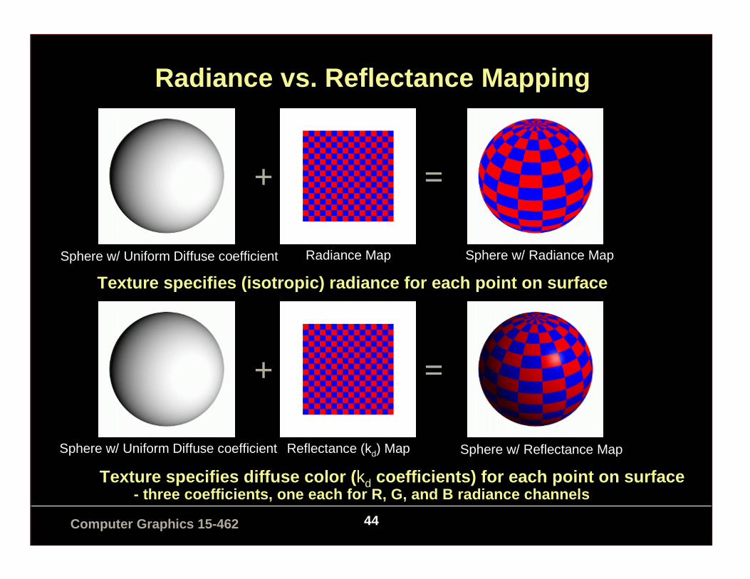
Radiance vs. Reflectance Mapping
+ =
Texture specifies (isotropic) radiance for each poi nt on surface
Sphere w/ Uniform Diffuse coefficient Radiance Map Sphere w/ Radiance Map
+ =
Texture specifies diffuse color ( kd coefficients) for each point on surface- three coefficients, one each for R, G, and B radia nce channels
Sphere w/ Uniform Diffuse coefficient Reflectance (kd) Map Sphere w/ Reflectance Map

45Computer Graphics 15-462
Multitexturing
(See RedBook p.422 for details)

46Computer Graphics 15-462
Bump Mapping: A Dirty Trick• Which spots bulge out, and which are indented?
• Answer: None! This is a flat image.
• The human visual system is hard-coded to expect light from above
• In CG, we can perturb the normal vector without having to make any actual change to the shape.

47Computer Graphics 15-462
Bump Mapping• Basic texture mapping paints on to a smooth surface• How do you make a surface look rough?
– Option 1: model the surface with many small polygons– Option 2: perturb the normal vectors before the shading calculation
+ =
Sphere w/Diffuse Texture Map Bump Map Sphere w/Diffuse Texture + Bump Map
Real Bump Fake Bump Flat Plane

48Computer Graphics 15-462
Bump Mapping• Basic texture mapping paints on to a smooth surface• How do you make a surface look rough?
– Option 1: model the surface with many small polygons– Option 2: perturb the normal vectors before the shading calculation
» the surface doesn’t actually change, but shading makes it look that way
» bump map fakes small displacements above or below the true surface» can use texture-mapping for this
– texture image gives amount to perturb surface normal
What kind of anomaly will this produce?
Greg Turk

49Computer Graphics 15-462
Bump Mapping
Let be a point on a parametric surface.Unit normal is
Where
are partial derivative vectors tangent to the surface at point P
( )vu,p
|| vu
vu
pppp
n××=
������
�
�
������
�
�
∂∂∂∂∂∂
=
u
zu
yu
x
up
������
�
�
������
�
�
∂∂∂∂∂∂
=
v
zv
yv
x
vp

50Computer Graphics 15-462
Bump Mapping
Displace the surface in the normal direction by
Then
We don’t actually change the surface (p), just the normal. Need to calculate:
( )vud ,
( )npp vud ,' +=
''' vu ppn ×=

51Computer Graphics 15-462
Bump MappingCompute the partial derivatives by
differentiating p’
If d is small
Pre-compute arrays of
uu vudu
du
nnpp ),(' +∂∂+=
vv vudv
dv
nnpp ),(' +∂∂+=
uv u
d
v
dpnpnnn ×
∂∂+×
∂∂+='
u
d
v
d
∂∂
∂∂
,

52Computer Graphics 15-462
Bump Mapping
• We can perturb the normal vector without having to make any actual change to the shape.
• This illusion can be seen through—how?
Original model (5M) Simplified (500) Simple model with bump map
53Computer Graphics 15-462
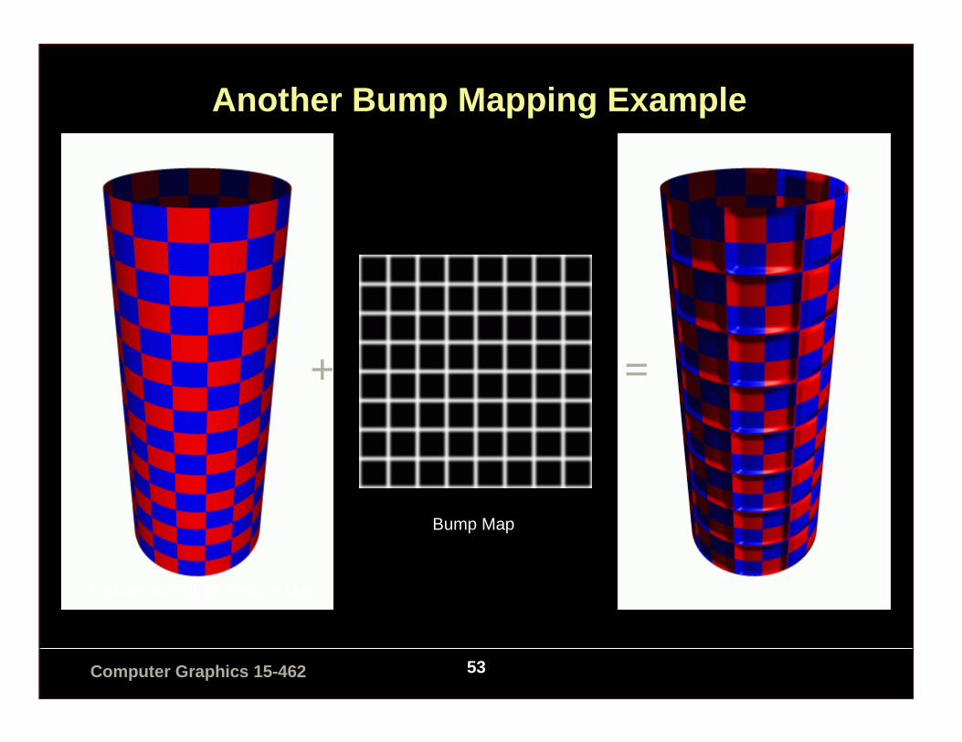
Another Bump Mapping Example
+ =
Cylinder w/Diffuse Texture Map
Bump Map
54Computer Graphics 15-462
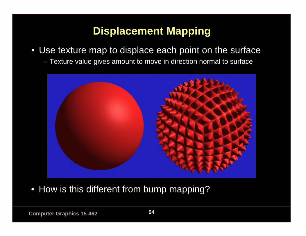
Displacement Mapping
• Use texture map to displace each point on the surface– Texture value gives amount to move in direction normal to surface
• How is this different from bump mapping?

55Computer Graphics 15-462
Environment Mapping
Specular reflections that mirror the environment

56Computer Graphics 15-462
Environment Mapping
Specular reflections that mirror the environment
Cube is a naturalintermediate object for a room

57Computer Graphics 15-462
Environment Mapping
• Generate the environment map either by scanning or by rendering the scene from the point of view of the object (win here becausepeople’s ability to do the reverse mapping in their heads is bad—they won’t notice flaws)
• OpenGL can automatically generate the coordinates for a spherical mapping. Given a vertex and a normal, find point on sphere thathas same tangent:
glTexGenfv(GL_S, GL_SPHERE_MAP,0);
glTexGenfv(GL_T,GL_SPHERE_MAP,0);
glEnable (GL_TEXTURE_GEN_S);
glEnable (GL_TEXTURE_GEN_T);

58Computer Graphics 15-462
Environment Mapping: Cube Maps

59Computer Graphics 15-462
More Tricks: Light Mapping• Quake uses light maps in addition to (radiance) texture maps. Texture
maps are used to add detail to surfaces, and light maps are used to store pre-computed illumination. The two are multiplied together at run-time, and cached for efficiency.
Radiance Texture Map Only Radiance Texture + Light Map
Light Map