TETRA TECH - Pigeon Lakepigeonlake.org/PastPlans/Tetra Tech Report of Exploration.pdf · TETRA TECH...
20
TETRA TECH August 17, 2007 Pigeon Lake Protection and Rehabilitation District Attn: Mr. Dennis Krueger Clintonville, Wisconsin 54929 SUBJECT: Report of Exploration Pigeon Lake Drawdown Potential Clintonville, Wisconsin Tetra Tech Project No. 7340178 Dear Mr. Krueger: Per your request, we have collected sediment samples for classification and laboratory testing to determine the potential effect of a drawdown of Pigeon Lake. This report summarizes our exploration and findings, and presents our recommendations for the potential results of a drawdown. The soil samples obtained in the field will be retained at our office for two months. The samples will then be discarded unless we are requested to hold them for a longer period. We appreciate the opportunity to be of service to you on this project. If you have any questions concerning this report, or if we can be of further assistance as this project develops, please contact us at (715) 845-4100. Sincerely, TETRA TECH Andy Walters, E.1.T Geotechnical Engineer Drilling Department Manager AW SAGEOTECH\2007jobsWigeon Lakelreport 081707.000 Attachments Tet.ra Tech, icc, 565 South 72"' Avenue, Wausau, WI 54401 715.845.4100 i'".3x 715.842.0381 www.tetratethcorn
Transcript of TETRA TECH - Pigeon Lakepigeonlake.org/PastPlans/Tetra Tech Report of Exploration.pdf · TETRA TECH...

TETRA TECH
August 17, 2007
Pigeon Lake Protection and Rehabilitation District Attn: Mr. Dennis Krueger Clintonville, Wisconsin 54929
SUBJECT: Report of Exploration Pigeon Lake Drawdown Potential Clintonville, Wisconsin Tetra Tech Project No. 7340178
Dear Mr. Krueger:
Per your request, we have collected sediment samples for classification and laboratory testing to determine the potential effect of a drawdown of Pigeon Lake.
This report summarizes our exploration and findings, and presents our recommendations for the potential results of a drawdown. The soil samples obtained in the field will be retained at our office for two months. The samples will then be discarded unless we are requested to hold them for a longer period.
We appreciate the opportunity to be of service to you on this project. If you have any questions concerning this report, or if we can be of further assistance as this project develops, please contact us at (715) 845-4100.
Sincerely, TETRA TECH
Andy Walters, E.1.T Geotechnical Engineer Drilling Department Manager
AW SAGEOTECH\2007jobsWigeon Lakelreport 081707.000
Attachments
Tet.ra Tech, icc, 565 South 72"' Avenue, Wausau, WI 54401
715.845.4100 i'".3x 715.842.0381 www.tetratethcorn
Report of Exploration
Pigeon Lake Drawdown Potential Clintonville, Wisconsin
Prepared for:
Pigeon Lake Protection and Rehabilitation District
Waupaca County Clintonville, Wisconsin 54929
Prepared by:
Tetra Tech
555 South 72'd Avenue Wausau, Wisconsin 54401 (715) 845-4100 Fax (715) 842-0381 Tetra Tech Project No. 7340178
August 17, 2007
121.1;e0i; 10!
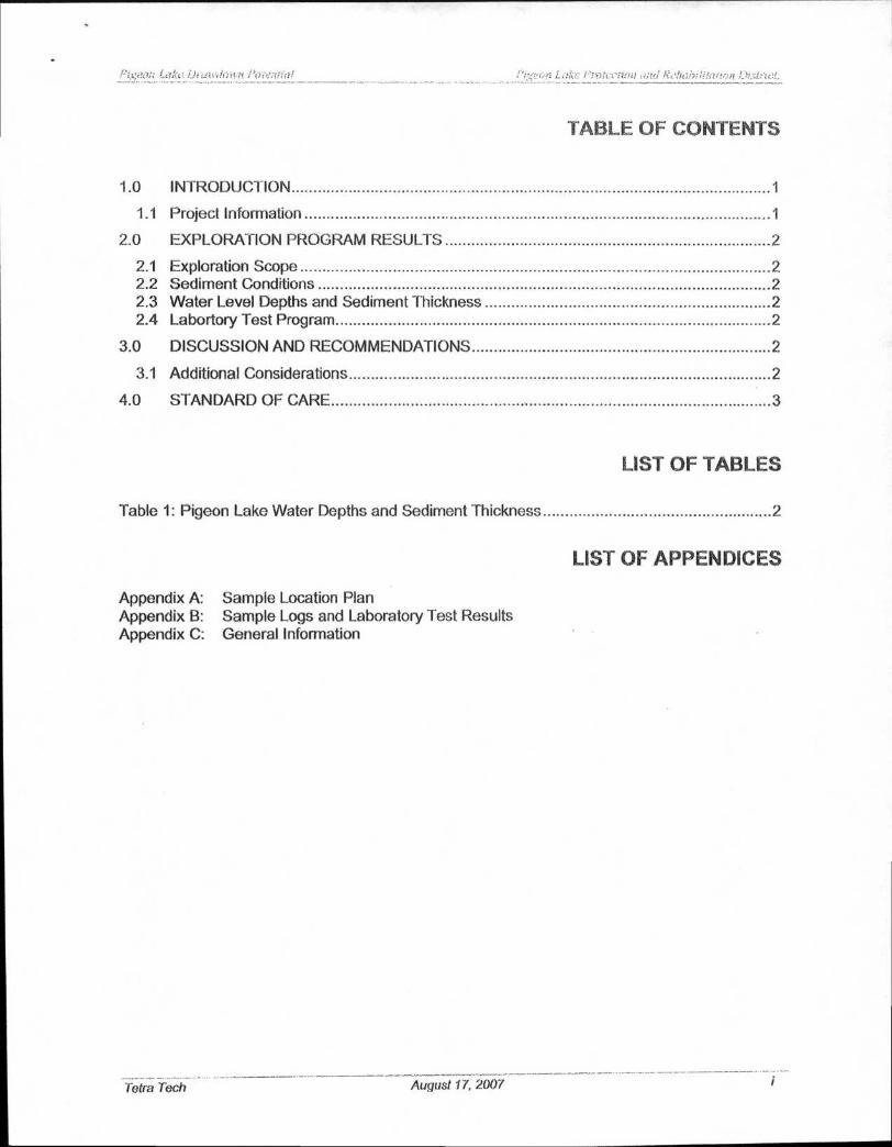
TABLE OF CONTENTS
1.0 INTRODUCTION 1
1.1 Project Information 1
2.0 EXPLORATION PROGRAM RESULTS 2
2.1 Exploration Scope 2 2.2 Sediment Conditions 2 2.3 Water Level Depths and Sediment Thickness 2 2.4 Labortory Test Program 2
3.0 DISCUSSION AND RECOMMENDATIONS 2
3.1 Additional Considerations 2
4.0 STANDARD OF CARE 3
LIST OF TABLES
Table 1: Pigeon Lake Water Depths and Sediment Thickness 2
LIST OF APPENDICES
Appendix A: Sample Location Plan Appendix B: Sample Logs and Laboratory Test Results Appendix C: General Information
Tetra Tech
August 17, 2007

'11'di,1 11.7 2 “,
etk Rairthifazlric:n
1.0 INTRODUCTION
This report has been prepared to aid in the evaluation of alternatives to increase lake depth for Pigeon Lake in Waupaca County near Clintonville, Wisconsin. This report includes exploration data, laboratory and engineering analysis, and recommendations for the potential drawdown results for the proposed project.
The primary purpose of the exploration was to determine the stratigraphy and physical properties of the sediment soils lining the lake bottom, particularly the potential settlement a lake drawdown would cause.
The analysis and recommendations presented in this report is under the assumption that variations in the sediment soils exist, but is based solely upon the samples collected.
This report is not intended to document or detect the presence, or absence, of any environmental conditions at the site, nor to perform an environmental assessment of the site.
1.1 Project Information
We understand the Pigeon Lake Protection and Rehabilitation District is evaluating alternatives to increase lake depth. Tetra Tech has been tasked to provide recommendations for the potential results of a lake drawdown. Mr. Dennis Krueger authorized Tetra Tech to perform the exploration at this site.
2.0 EXPLORATION PROGRAM RESULTS
2.1 Exploration Scope
On June 21, 2007, 4 locations of Pigeon Lake were sampled by collecting bulk samples and PVC Tube samples for sediment classification and laboratory testing. The PVC Tube samples were collected by directly pushing the tubing in the sediment layer and capping the tube ends for sample preservation. A sample location diagram is included in Appendix A.
The samples recovered were returned to our laboratory for testing, and reviewed by a geotechnical engineer. The soil classifications are in accordance with the Unified Soil Classification System (USCS).
2.2 Sediment Conditions
The laboratory tests indicate the sediment sampled contained between 6.4 to 42.9 percent organic material. Of the four sample locations, only sample location PL•3 encountered fine grained cohesive soils (clay). Sample locations, PL-1, PL-2, and PL-4 each encountered granular, cohesionless soils (silt and sand).
Detailed descriptions of the soils encountered are provided on the boring logs included in Appendix 8.
Tetra Tech August 17, 2007
SAMPLE LOCATION
SEDIMENT THICKNESS
WATER DEPTH
3.5 FT
5.0 FT
3.0 FT
5.0 FT
PL-1
PL-2
PL-3
26 INCHES
23 INCHES
23 INCHES
PL-4 30 INCHES
arct i rde}:11 Pown tok e Prmeetioo bili Distreop. .... .
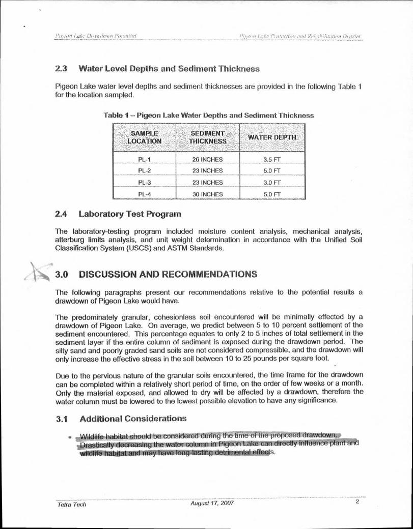
2.3 Water Level Depths and Sediment Thickness
Pigeon Lake water level depths and sediment thicknesses are provided in the following Table 1 for the location sampled.
Table 1 — Pigeon Lake Water Depths and Sediment Thickness
2.4 Laboratory Test Program
The laboratory-testing program included moisture content analysis, mechanical analysis, atterburg limits analysis, and unit weight determination in accordance with the Unified Soil Classification System (USCS) and ASTM Standards.
3.0 DISCUSSION AND RECOMMENDATIONS
The following paragraphs present our recommendations relative to the potential results a drawdown of Pigeon Lake would have.
The predominately granular, cohesionless soil encountered will be minimally effected by a drawdown of Pigeon Lake. On average, we predict between 5 to 10 percent settlement of the sediment encountered. This percentage equates to only 2 to 5 inches of total settlement in the sediment layer if the entire column of sediment is exposed during the drawdown period. The silty sand and poorly graded sand soils are not considered compressible, and the drawdown will only increase the effective stress in the soil between 10 to 25 pounds per square foot.
Due to the pervious nature of the granular soils encountered, the time frame for the drawdown can be completed within a relatively short period of time, on the order of few weeks or a month. Only the material exposed, and allowed to dry will be affected by a drawdown, therefore the water column must be lowered to the lowest possible elevation to have any significance.
3A Additional Considerations
e Wildlife habitat should be considered during the time of the proposed drawdown. Drastically decreasing the water column in Pigeon Lake can directly influence plant and
11111011111111bitat and may have long-lasting detrimental effects.
Tetra Tech
August 17, 2007 2
■ • 4,1•1) 1 1?,0hrisu.ri , 1 17-1 ,Ae6Tivion i); ,-/r.et
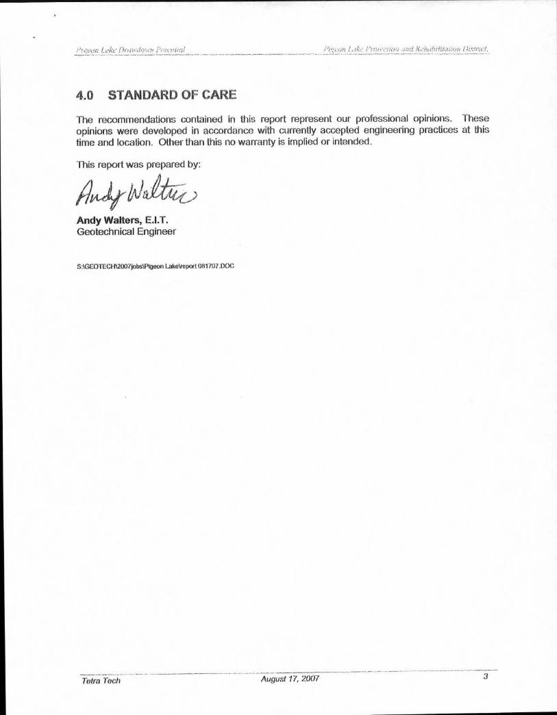
4.0 STANDARD OF CARE
The recommendations contained in this report represent our professional opinions. These
opinions were developed in accordance with currently accepted engineering practices at this
time and location. Other than this no warranty is implied or intended.
This report was prepared by:
Andy Walters, E.I.T. Geotechnical Engineer
SAGEOTECH12007jobsiPigeon LakeVeport (181707.DOC
.....
Tetra Tech August 17, 2007 3
X 0,44 9we, A
APPENDIX A
SAMPLE LOCATION DIAGRAM

APPENDIX B
SAMPLE LOGS LAB TEST RESULTS
Project Name: Pigeon Lake
Borehole Location: See Sample Location Plan _ ____ _
Borehole Number; PL-1 Driller: Neal Thieme Logger: Clint Eiden
Drilling Equipment: Direct Push PVC Borehole 2 Date Started: 6/21/07 Date Finished: 6/21/07 Diameter (in.): Elevation Ground: and Datum: Notes:
DEPT
H (ft
)
P OCK
E T PE
NTAM
E TER
(Op)
1
kIVIP
LE N
U MBE
R z
SAM
PLE
STAN
DAR D
PE
NETR
ATIO
N ! T
EST
(blow
s/ft) W ifi 0
-4 >-
MOI
STU R
E CO
NTE N
T (%
)
4.-:-
Fj.
-0 I P
LAST
ICIT
Y IN
DE
X
GRAP
HIC
LOG
o z
w :..) MATERIAL DESCRIPTION
CI 0
a O.
CY - O.
0 SPT 0 LL N in
47t. X
V cl
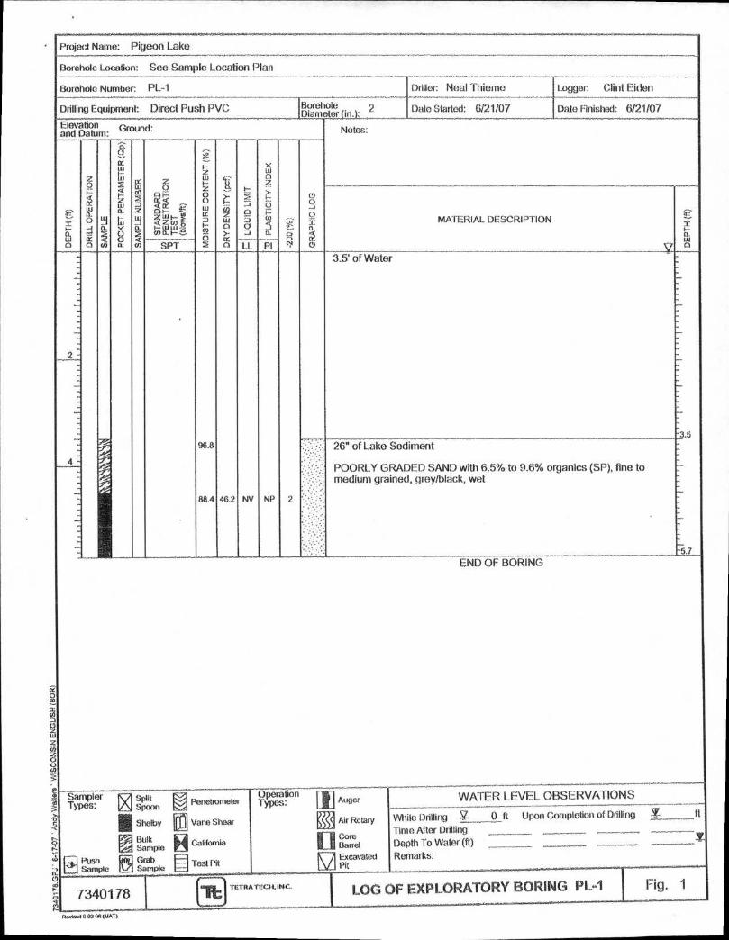
3.5
2-
_
•
3.5' of Water
96.8 ....I•: 26" of Lake Sediment
ye::1 :. POORLY GRADED SAND with 6.5% to 9.6% organics (SP), fine to — - medium grained, grey/black, wet
88.4 46.2 NV NP 2 V . _
-5.7 END OF BORING
samPler ar4 SPIlt 0 Penetrometer I / Auger TypeS: w spoon Types: Operation WATER LEVEL OBSERVATIONS
ill Shelby iti Vane Shear g i Air Rotary While Drilling V_ p ft Upon Completion of Drilling t ft
Time After Drilling ril Bulk California 11 Barrel Depth To Water (ft) _______ ____ 'KT.. Sample
tiH Push
IN Grab Test Pit NA Excavated Remarks:
7340178 it TETRA TEC1A, INC. LOG OF EXPLORATORY BORING PL-1 Fig. 1
601-0.1 (AT)
U.S. SIEVE OPENING IN INCHES
4 2 1 1/2 6 3 1.5 314 1/2 :
U.S. SIEVE NUMBERS
6 10 14 1° 20 30 40 50 60 100 140 200
I I r HYDROMETER
100
00
70
80
m
Zw 50 LL
40
a.
30
20
10
100
10
01
0.01
0.001
GRAIN SIZE IN MILLIMETERS
COBBLES GRAVEL SAND
SILT OR CLAY coarse j fine coarse [medium 1 fine
Specimen Identification Classification
LL
PL PI
Cc
Cu
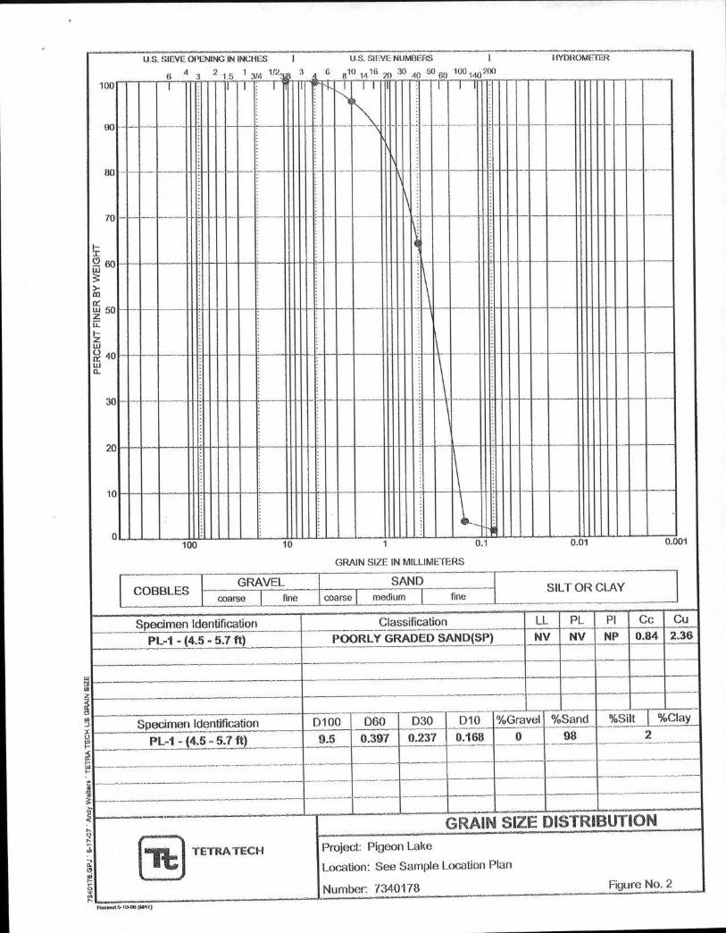
PL-1 - (4.5 - 5.7 ft)
POORLY GRADED SAND(SP)
NV NV NP 0.84 2.36
an
Specimen Identification
D100
PL-1 - (4.5 - 5.7 ft) 9.5 D60 D30 D10
0.397 0.237 0.168
%Gravel %Sand %Si t %Clay
0 98 2
GRAIN SIZE DISTRIBUTION Project: Pigeon Lake
Location: See Sample Location Plan
Number 7340178
ro
rb
I. 0 an
O
TETRA TECH
Figure No. 2
firviend r,-10.36 (MAT)

Project Name: Pigeon Lake
Borehole Location: See Sample Location Plan
Borehole Number: PL-2 Driller Neal Thiome Logger. Clint Eiden _
Drilling Equipment: Direct Push PVC Borehole - 2 plarne etraii Date Sta rted : 6/21/07 rt d Date Finished: 6/21/07
Elevation Ground: and Datum: Notes:
DE
PTH
(ft)
DR
ILL O
PE
RA
TIO
N
SA
MP
LE
PO
CK
ET
PE
NTA
ME
TER
(Q
p)
SA
MP
LE N
UM
BE
R
ST
AN
DA
RD
P
EN
ET
RA
TIO
N
TE
ST
(b
low
s / t)
MO
IST
UR
E C
ON
TEN
T ( %
)
DR
Y D
EN
SIT
Y (
pc f)
LIQ
UID
LIM
IT
x ii, a 2 > t- o
e a 0
GR
AP
HIC
LO
G
MATERIAL DESCRIPTION
DE
PTH
(ft)
SPT LL PI
..
-.]
."-, ,"
9/ ..A.°
471.6
239.4 21.7
NV
NV
NP
NP
5' of Water
•
H
,.
_
4 -
ft -
37 •
• .
23" of Lake Sediment
SILTY SAND with 30% to 42.9% organics (SM), fine grained, black/grey, wet
:7
END OF BORING
Sampler Types:
K-7 Spoon IA si"xxx,
II Shelby
rq Moe
Push IN Grab Sample Sample
'. ;se
[a
H —
Penetrometer
Vane Shear
California
rest Pit
erat. 1°" Types. 11
El
r_l
FA
Auger
Air Rotary
trerel Excavated Pit
WATER LEVEL OBSERVATIONS
While Drilling SZ, 0 ft Upon Completion of Drilling I __ft
_ ______ Time After Drilling .
Depth To Water (ft) It
-- - Remarks:
7340178 LOG OF EXPLORATORY BORING PL-2 Fig. 3 h it TETRA TECH, INC.
U005.10-02-011 (NAT)
U.S. SIEVE OPENING IN INCHES I U.S. SIEVE NUMBERS I HYDROMEIER 4 2 1 1/2. 3 6 16 30 50 100 200 ..... 6 3 5 :4/4 3/8 4 20 40 60 140
PE
RC
ENT
FIN
ER
BY
WE
IGH
T
8 -84
0 0
st.
o
0
-'"N---
•
100 10 1 01 0.01 0.001
GRAIN SIZE IN MILLIMETERS
LCOBBLES GRAVEL SAND
SILT OR CLAY coarse Dina coarse medium I fine
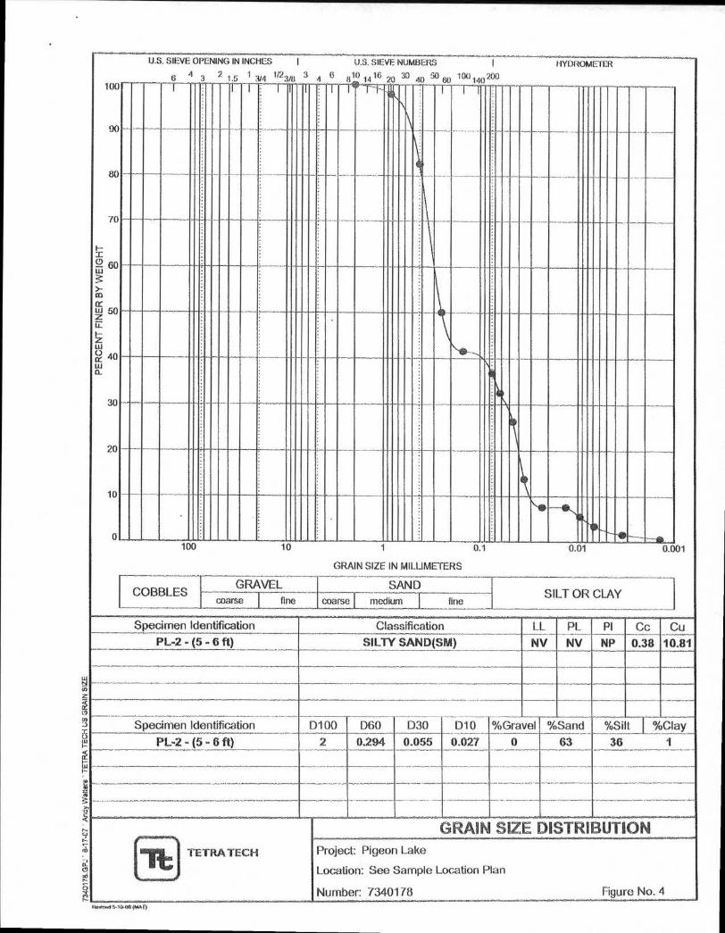
Specimen Identification Classification LL PL PI Cc Cu PL-2 - (5 - 6 ft) SILTY SAND(SM) NV NV NP 0.38 10.81
D100 D60 D30 D10 %Gravel %Sand %Silt %Clay Specimen Identification
PL-2 - (5 - 6 ft) 2 0.294 0.055 0.027 0 63 36 1
, -
TETRA TECH
GRAIN SIZE DISTRIBUTION Project: Pigeon Lake
Location: See Sample Location Plan
Number: 7340178 Figure No. 4 rioAnwl 5-10-06 (MAI)
0
a
Lu
in
0
9
(I
Project Name: Pigeon Lake
Borehole Location: See Sample Location Plan
Borehole Number: PL-3 Driller: Neal Thieme Logger: Clint Eiden
Drilling Equipment: Direct Push PVC Borehole 2 Diameter in.: Date Started: 6/21/07 Date Finished: 6/21/07
Elevation Ground: and Datum: Notes:
Zi.1
LH a D
RIL
L O
PE
RA
TIO
N
1 S
AM
PL
E
PO
CK
ET
PE
NTA
ME
TER
(00
1
IMP
LE
NU
MB
ER
ST
AN
DA
RD
P
EN
ET
RA
TIO
N
TES
T
(blo
wst
)
MO
ISTU
RE
CO
NTE
NT
(%)
DR
Y D
EN
SIT
Y (p
ar)
ea 5
• PLA
ST
ICIT
Y I
ND
EX
--I
e. -..
CI `1'
. „,,,
0
MATERIAL DESCRIPTION
DE
PTH
(ft)
SPT LL PI
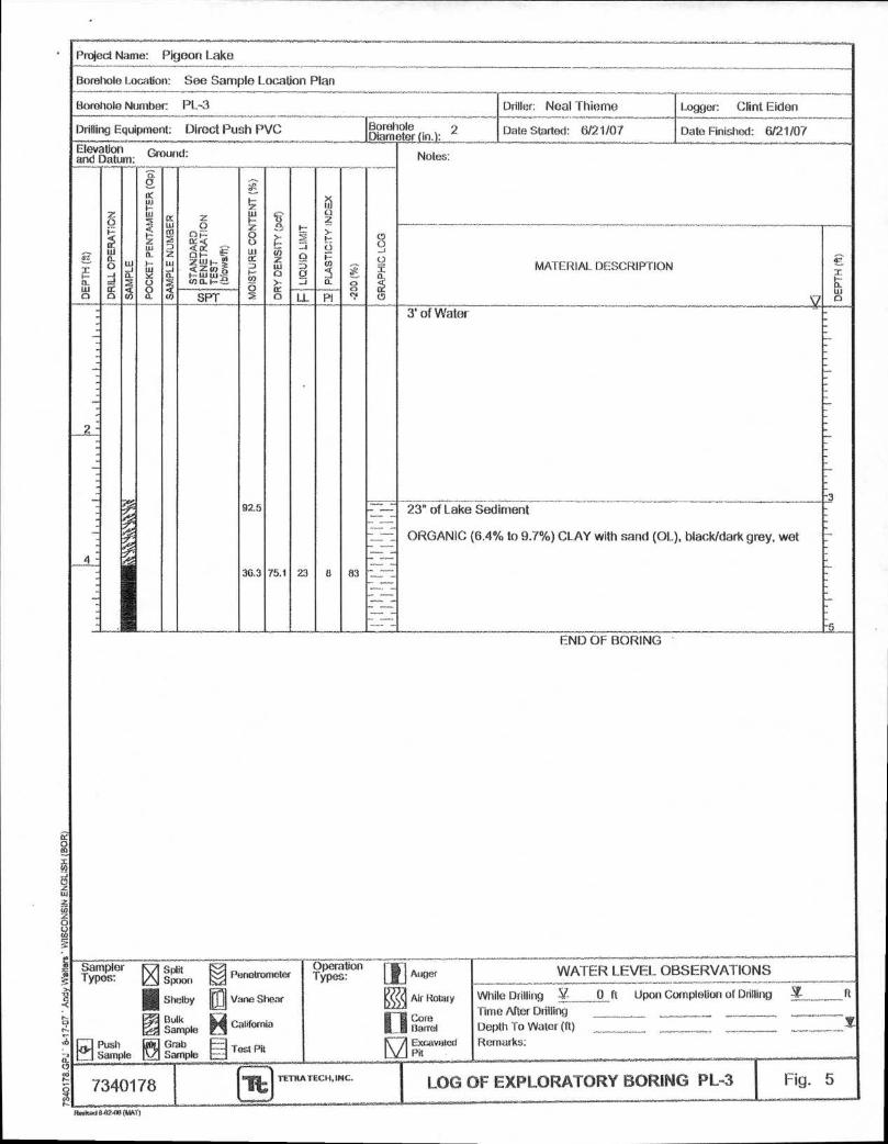
92.5
36.3 75.1 23 8 83
_
2 -
3' of Water
-3 - —
2_2"
_
— —
23” of Lake Sediment
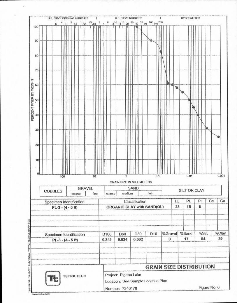
ORGANIC (6.4% to 9.7%) CLAY with sand (OL), black/dark grey, wet
... -
-..
_
-
-5 END OF BORING
..... Sampler ix Spoon
Types: sii-o twl, Penetrometer
Vane Shear
Operation [1] Auger Types: WATER LEVEL OBSERVATIONS
111 Shelby V : § Air Rotary While Drilling Sl- ft Upon Completion of Drilling I ft _.0
Time After Drilling
Lusi fl inple
rre,
i Bulk California H - i Sample Grab
. Lple E fest Pit
ri M
Barrel Excavated
Pit
Depth To Water (ft) _____
Remarks:
Fig. 5 7340178 TETRA TECH, INC. LOG OF EXPLORATORY BORING PL-3
Rericad (MAT)
U.S. SIEVE OPENING IN INCHES
0 4 1 1/2
I U.S. SIEVE
3 1.5 314 3/8 3 6
4 810
1 16
NUMBERS I
— 40 0 1i
0 ( ° 140 2°()
I IYDROMETER
30 00
PER
CE
NT
FIN
ER
BY
WE
IGH
T
• 0
_ —
100 10 1 0 1
GRAIN SIZE IN MILLIMETERS
0.01 0.001
GRAVEL [COBBLES -1
SAND SILT OR CLAY
coarse fine coarse medium r fine
Specimen Identification Classification LL PL PI Cc Cu
PL-3 - (4 - 5 ft) ORGANIC CLAY with SAND(01) 23 15 8
Specimen Identification D100 D60 D30 D10 %Gravel %Sand %Si t I %Clay
PL-3 - (4 - 5 ft) 0.841 0.034 0.002
GRAIN
0 17 54 29
.._
SIZE DISTRIBUTION
TETRA TECH
-
Project: Pigeon Lake
Location: See Sample Location Plan
Number: 7340178 Figure No. 6
14.0v1sed 6-10-00 (MAT)
0 co
a- u)
w
co 0 0 0
2 476- a. ro
Project Name: Pigeon Lake
Borehole Location: See Sample Location Plan
Borehole Number: PL-4 Driller: Neal Thiome Logger: Clint Eiden
Drilling Equipment: Direct Push PVC Borehole Diameter (in.):
2
Notes:
Date Started: 6/21/07
...,..—.--
Date Finished: 6/21/07
,1;.'
ElevatIor Ground: and Datt IN:
4,:, - : I-- a. LIJ 0
Z 0 F"
1
d --1 tr. 0 S
AM
PL
P
• -
1 PO
CK
ET
PE
NT
AM
ET
ER
I`C
p)1
I SA
MP
LE N
UM
BER
F 1,
1 S
TAN
DA
RD
_
i S
(Now
sift)
MO
IST
UR
E C
ON
TE
NT
%)
DR
Y D
.E. N
SIT
Y (
pc?)
I-
D a 5
.J
LL
P IN
'EX
1 -20
1: (
%)
....i o T. CI-
(9 IN
MATERIAL DESCRIPTION
8
..7f.'..-
..9-
...e..---4
.t,.-
-',..-4.- ..-e. .."-...e,
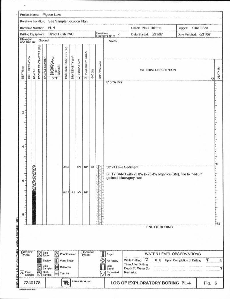
292.:
285.' 18.3
NV
NV
NP
NP
.343
5' of Water
-5
• . 30" of Lake Sediment
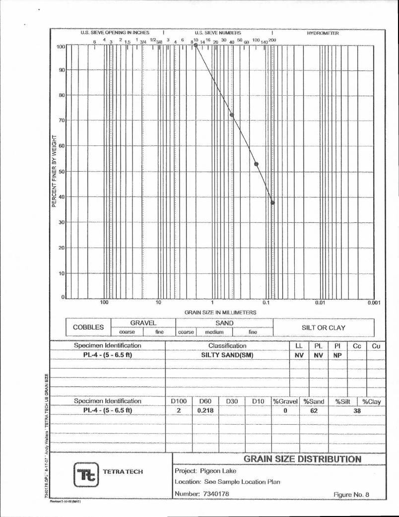
SILTY SAND with 23.8% to 25.4% organics (SM), fine to medium .. grained, black/grey, wet
..:
8.5 END OF BORING
Sampler Types:
Push Sample
;;A:
Split Spoon
Shelby
Bulk Sample Grab Sample
Penetrometer
Eal Vane Shear
H . . . Callfogisa
lest Pit
Operation Types:
to
Auger
I Air Rotaiy
WATER LEVEL OBSERVATIONS
While Drilling V- ____. 0 ft Upon Completion of Drilling
Time After Drilling
Depth To Water (ft) ______ _ Remarks:
_
I ft
........--........--..
111 Gore
pi Excavated
. Y.
• 340178 it TETI1A TECH, INC. LOG OF EXPLORATORY BORING PL-4 .... ........._
Fig. 6 .
RovrIPU 8-024K, (NA 11
U.S. SIEVE OPENING
4 2 6 3
IN INCHES I U.S. SIEVE NUMBERS I HYDROMETER
.5 1 1/23/8 6 10 16 30 50 100.140 200 3/4 3/8 4 8 14 40 60 1 20 40
PE
RC
EN
T F
INER
BY
WE
IGH
T
I,:44
. 4
.;
CT C
',4 C
O 8
0 8 C 0
o
0
0 C
c 8
0 1 I I I I I I l' I I I 1 r
i
100 10 1 01 0.01 0.001
GRAIN SIZE IN MILLIMETERS
GRAVEL SAND SILT OR CLAY COBBLES
coarse I tine coarse medium I., fine
Specimen Identification Classification LL PL PI Cc Cu PL-4 - (5 - 6.5 ft) SILTY SAND(SM) NV NV NP
Specimen Identification D100 D60 D30 010 %Gravel %Sand %Silt I %Clay PL-4 - (5 - 6.5 ft) 2 0.218 0 62 38
TETRA TECH
GRAIN SIZE DISTRIBUTION Project: Pigeon Lake
Location: See Sample Location Plan
Number: 7340178 Figure No. 8 Review 5-10414 (MAT)
TE E
APPENDIX C
GENERAL INFORMATION
SC Clayey sand G"'
PT Peat Highly organic sollS Primarily organic matter, dark In valor, and organic odor
Cnarse.Cirairied Soils
Mae than 50%
retained On No. ar0
sieve
More than SOS COMe lractieri retained on
No. 4 sieve
Clean Gravels Less than 5. ,„
fines
Gravels with Finns
More than 12% fines
Ca S and 1 5 Cc c 5'
Cu < 4 3nd'or 1 > Cc >
Fines classify as ML or MI-I
Fines class:ly as CL or ClA
Sands
50% or more of
coarse faction passes No 4 S:Ova
Clean Sands Less than 5%
fines
Sands with Fines
Mn 123 Ore t an 'a fines
Ci: z 6 and 1 s Cc 5. 3'
Cu < 0 and;ur 1> Cc > 3E
Fines classify as ML or MN
Fines classify as CL or CH
Fine-Grained Sous 561tor more passes
the No. 200 sieve
Silts and Clays Liquid firm less
than 50
Silts and Clays Liquid lend 50 or
more
Inorganic
Pi a 7 and plots on or above -11'.
line
PI < 4 or plots below 'A" line
Organic
Inorganic
L:NgidIiinit_7 oven dried Liquid limit - not dried 4 "S .
PI plots on Of atmv0 "A' line
PI plots below W line
Organit: Liquid Said= oven dried
Liquid limit --not dried 676
Organic clat'''" MN •
Organic sill
OL Organic sill u°
ML Sat
CH Fat clay 4 "
• MH Elastic sift
UH Organic clay'''L " O
•••••••••••..•••••••••
SW Well-graded sand
SF' Poorly graded sand
SM Silly Sand
OW ',Ned graded gravel'
GP Poorly graded gravel'
GM Silty gravel
GC Clayey gravel 6 "
CL Leafs clay
. I rCn.„,...
)0
ref itill$ of , C.04 OA 01 ',I...21.11 1011{
7,73-f 7i47-1-c-iliiirriViITOZO f 5 00717--1741 ,4"a • -• 10.1 i H 50 —"- IL Eguraild. tof .4. - law
ika,r3.11 0 I. PI-4 to LL - 25 5. Lat, I ia-a P1-0 75 lt.L- 201
so 41.- i • of • 0 . - 0 ,1
"... '1:11 ', 14'..1.7. . 0,101 Lk . is , C PI"
f. Y" thy. P1•0 91L1. - Is / ,..
5., .-
s'a
,I7F-t75; " s 6
.4;.;
L Od l i: L.IMiS ILL 1
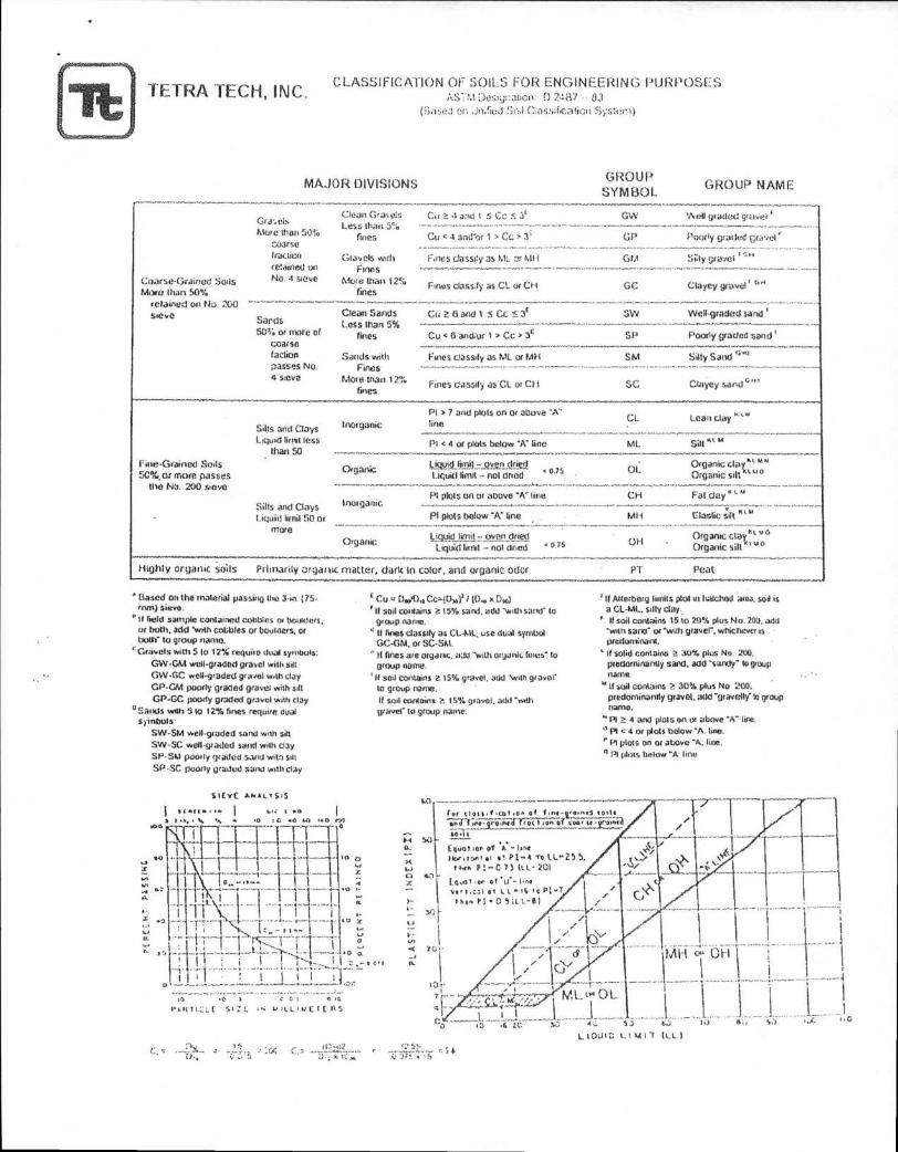
TETRA TECH, INC. CLASSIFICATION OF SOILS FOR ENGINEERING PURPOSES
M Desiirotiow 0 24i17
Viased (•; jrVIG:1 Sr;.1C:assif:catioo S ,;s:er
MAJOR DIVISIONS GROUP
SYMBOL GROUP NAME
Based on the material passing the 3-in. (75- mm) sieve.
It field sample contained cobbles cm bouiders, or both. add with cobbles or boomers, or both" to group name.
`Gravels with 5 to 12% require dual symbols:
GW•GAA weir•graded gravel with sill GW•GC wee-graded gravel with Clay
GP-GM poorly graded grave: with silt GP-GC poorly graded gravel with clay
° Sands with 5 to 12% fines require dual symbols:
SW-SM wen-graded sand with rah SW-SC well-graded sand with clay
SP-SM primly graded sand with sill
SP-SC poorly graded sand with clay
Sit YE AN al. , SIS
IL 41.• I ♦ , I MO
I a w, • 405.0 .0 VY)
) it,
IL 11 $
C •r :*
Cu .• Cc= 1 0.011 't D '1) '11 soil conlains a 15% sand. add "with sand - to
group name.
4 11 fines classify as CL-ML, use dual symbol GC-GM, or SC-Sht.
II fines are organic, add "with ()manic firms" to group name.
It sod contains 5 15% gravel, add 'with gravel' to group name. If soil contains P 15% gravel, add ',am gravel' to group name.
' If Atterbarg limits plot in lialchod area. soil is a GL-ML, silty clay,
". If soil contains 15 to 29% plus No. 200, add "with said" or 'vvith graver, whichever is predominant.
If solid Contains 1,, 30% plus No. 200. predominantly sand, add -sandy' to group name.
" If 50i1 contains IP. 30% plus No 200. predominantly gravel, add "gravelly' le group name.
" Pt 4 and plots OR Or above 'A" tine.
PI < 4 or lots below A. line.
PI plots On or above "A: fine.
° P1 plots below "k line
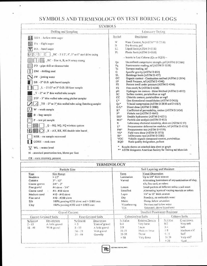
SYMBOLS . _ Drilling and Sampling Labor:J.1,3:v Test.im IF
141P liSA - hallow stem auger
l'A - nigh; auger
rffl - hand auger
,..7] _ 2 1:2",1", 5" or 6" steel drive casing
fillfi RH _RC - Size A, 11, or N rotary casing
P1) - pipe drill or cleanout tube
En - drilling mud
JW -jetting water
In SD -2" U.D. split barrel sample
[Di L - 2 112" or 3" U.D. SB liner sample
- 2" or 3" thin walled tube sample
[113l 3TP 3" thin walled tube using pitcher sampler
TO - 2" or 3" thin walled tube using Osterberg sampler
[2] w _wash sample
13 - bag sample
- test pit sample
n - 11Q, NQ, PQ wireless system
Lal"71 L\I _X - AX, 13X, NX double tube barrel
I
NSR - no sample recovered
CI CORE - rock core
V • WL water- level
N standard penetration test, blows per foot
CR - core recovery, percent
\Vigo Content, % (Asim" 13 72i 6) 1)
l3ry density, per
LL
Liquid lunar (ATS.vI [) •1316} Plastic I unit (ASTM 0 4315)
-• Inserts in Las: (Qt: or RQD)
Qtt Unconfined compressive strength, psf (AS CM 1) 2166) l'q Penetrometer reading, tsf (ASTM 1) 1558)
is Torvane reading, tsf
G Specific gravity (ASTM D 854) SI, Shrinkage limits (ASTM D 427) CC Organic content - Combustion method (ASTM D 2974) SP Swell Pressure, tsf (ASTM 0 4546) PS Percent swell under pressure (ASTM 13 4546)
ES Free swell, • (ASTM 0 4546) pH Hydrogen ion content - Meter Method (ASTM D 4972) SC Sulfate content, parts/million or rug/1 CC. Chloride content, parts/million or mgd
C" One dimensional consolidation (ASTM 10 2435) Qc• Triasial compression (ASTM 0 28 50 and l) 4767) DS.° Direct shear (ASTM I) 3080)
K° Coefficient of permeability, cm/sec (AsTmn 2434) P• Pinhole test (ASTM 1) 4647)
Dli• Double hydrometer (ASTM 0 4221) MA" Particle sin analysis (ASTM 0 422)
R Laboratory electrical resistivity, ohm-cm (ASTM Cl 57)
E• Pressuremeter deformation modulus, tsf (ASTM 0 4719) PM• Pressurcmetcr test (ASTIvt I) 4719) VS• Field vane shear (ASTM 0 2573) 111.• 111111am -rider test (ASTM 1) 3385) VOC Volatile organic compound content, panstmillion RQD Rock quality designation, percent
' Results shown on attached data sheet or graph • ° ASTM designates American Society for Testing and Materials
VI LA
TERMINOLOGY Particle Size Soil Layering and 'Moisture
Size Rangy 1c1111 Visual Observatio!I
Boulders >12" Lamination to 1/4" thick stratum
Cobbles
Coarse gravel 3" - 12'
3/4" - 3"
V arved A hemating laminations of any combination of clay,
silt, fine sand, or colors
Fine grade' 1r4 sieve - 3/4" Lenses Small pockets of different soils in a soil mass
Coarse sand 114 - 1110 sieve Stratified Alternating layers of varying materials or colors
Medium sand //10 ft4 0 sieve Layer 1/4" to 12" thick stratum
line sand n-10 - /no° sieve Dry Powdery, no noticeable water
Sill 100% 'sassing tr2C0 sieve and > 0.005 min Moist Damp, bclow saturation
Clay 100% passing /1200 and < 0.005 trim Waterbeartne,
Wet
Peo.aou!, soil Letow wzazr
Saturated, above liauld limit
Gravel Coa:elit Sw.- .1. • 1- ;: Pcnirtr4iion itetiistaila 1 __________________.. ._
Coarse-Gm:lie:I Soils 1 Fine-Gra:112d Sods I C:oliesienless Sails I Coliriive Soils
%L.Q.EA:Ke I 1?V..Z.I3;' .0gl `!!it.n.r.;1Y:1 Dem-o.:: noon '...; - \:_et4 f!,ti;:',iYr-lier.i...:!%, i l'.. \:"..:Iii.IA Cr vi :.!4..411..1 2 - 15 A lio!e gravel < 5 Trace or gravel 0-• Vary ',twit I 0-1 Very soft
> 3()
16 - 49 %•C;:it gr:,, c.., 5 - 15 A lt:tl.:_gra+ -:.1 i 5.9 I .o,..se ! 3- 4 Soli
31 - 40 Gravelly
l'2.1..A
> 50
30-50
Ni.,::::.m ., ...:.r.sr. i L'•?,
'....):::.s
V-zry deoLa
i.,. :5
16• .10
N4crlitan 5::1:7
Star
Very stiff
1 6 - :0 '...'.',;11 g:a.,:el
SYMBOLS ,AIND TERMINOLOGY ON TEST BORING LOGS
TiTRATECN, ,NC.
RELATIVE DENSITY
Sands & Gravels
1
SM* Blows;Ic3t
Very Loose
Lied De•.s..1 Dense Ver7
0 -4
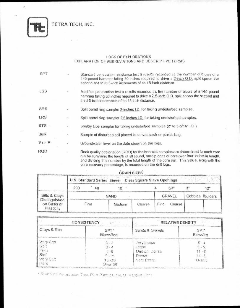
TETRA TECH, INC.
LOGS OF EXPLORATIONS EXPLANATION OF ABBREVIATIONS AND DESCRIPTIVE TERMS
SPT
Standard penetration resistance test :1 results recorded as the number of blows Of a 140-pound hammer falling 30 inches required to drive a 2-inch O.D. split spoon the second and third 6-inch increments of an 18-inch distance.
LSS
Modified penetration test 13 results recorded as the number of blows of a 140-pound hammer falling 30 inches required to drive a 2.5-inch 0.0. split spoon the second and third 6-inch increments of an 18-inch distance.
SRS
LRS
STS •
Bulk
V or Y
ROD
Split barrel ring sampler 2-inches I.D. for taking undisturbed samples.
Spilt barrel ring sampler 2.5 inches. LLD. for taking undisturbed samples.
Shelby tube sampler for taking undisturbed samples (2" to 3-5/16" 1.0.)
Sample of disturbed soil placed. in canvas sack or plastic bag.
Groundwater level on the date shown on the logs.
Rock quality designation (ROD) for the bedrock samples are determined for each core run by summing the length of all sound, hard pieces of core over four inches in length, and dividing this number by the total length of the core run. This value, along with the core recovery percentage, is recorded on the drill logs.
GRAIN SIZES:
U.S. Standard Series Sieve. Clear Square Sieve Openings
200 . 40 10 ' 4 3/4" 3" 12"
Silts & Clays Distinguished on Basis of
Plasticity —
SAND GRAVEL Cobbles Boulders
Fine -
Medium
—
Coarse Fine Coarse - -
_
CONSISTENCY .
Clays & Silts SPT•
..... Blows/foot
Very. Sf.):t 2 Soft 3 - 4
5 -8 Stiff 5 Vory 1 -39 Hard
• . 1