Testing of the First Part of Series Production 10MW MBKs ...
3
TESTING OF THE FIRST PART OF SERIES PRODUCTION 10MW MBKS FOR THE XFEL PROJECT V. Vogel, L. Butkowski, S. Choroba, A. Cherepenko, J. Hartung, V. Kachaev, R. Wagner. DESY, 22607 Hamburg, Germany Abstract At present more than half of 27 of 10 MW horizontal multi-beam klystrons (MBK) manufactured by two companies for the European XFEL project have been delivered to DESY. After delivery each klystron is connected to the connection module (CM), a HV oil tank with integrated HV connector, voltage and current monitors and a coaxial filament transformer, tested on the test stand and, if necessary conditioned. After this the klystrons are ready for installation in the underground linear accelerator tunnel. Two MBKs are already installed at the injector area of the XFEL. For the European XFEL project MBKs which can produce RF power of 10 MW, at RF frequency of 1.3 GHz, 1.5 ms pulse length and 10 Hz repetition rate, were chosen as RF power sources. During the incoming test the most important parameters of the MBK such as bandwidth, filament power, perveance, gain at different cathode voltage, phase stability and sensitivity to the solenoids current setting are measured and documented. In this paper we will give an overview of the test procedure, summarize the current test results and give a comparison of the most important parameters for several tubes. INTRODUCTION Two companies, “Thales” with MBK TH1802 [1] and “Toshiba” with MBK E3736H [2], started klystrons delivery for the European XFEL project in 2012. By the end of 2014 DESY should have MBKs for all 27 RF station of the XFEL. The main parameters of the MBKs are given in Table 1. Table 1: Main parameters of L-band MBK for XFEL Parameters Design value Test value Output power (MW) 10 9.9-10.5 RF pulse length (ms) 1.5 1.5 Efficiency (%) > 63 63-68 Repetition rate (Hz) up to 30 10 A verage RF power (kW) 150 155 Collector power (kW) 300 270 Max drive power (W) <200 <200 Bandwidth (MHz) 3 >3 All klystrons delivered in DESY were first connected to a connection module, CM, that had been produced by BINP Novosibirsk [3, 4 and 5] and then conditioned and tested in one the MBK test stands [6, 7 and 8]. The average time of conditioning and testing for the TH1802 is about 330 hours and for the E3736 about 280 hours. The tubes were conditioned up to full RF power and full RF pulse length with a repetition rate of 10 Hz. Figure 1 shows the top view of the test stands. Figure 2 shows one of klystrons with CM and HV cable inside of the test chamber. During acceptance test of MBK, in addition, two HV cables “NEXAN” with “PFISTERER 3S” connector were tested for about 11,000 hours. The test didn’t show any sign of degradation or increasing level of partial discharge. Figure 1: MBK test stands at DESY Hamburg Figure 2: HV connection between pulse transformer and MBK, connectors’ type “PFISTERER 3S” Proceedings of LINAC2014, Geneva, Switzerland TUPP023 01 Electron Accelerators and Applications 1D FELs ISBN 978-3-95450-142-7 481 Copyright © 2014 CC-BY-3.0 and by the respective authors
Transcript of Testing of the First Part of Series Production 10MW MBKs ...

TESTING OF THE FIRST PART OF SERIES PRODUCTION 10MW MBKS FOR THE XFEL PROJECT
V. Vogel, L. Butkowski, S. Choroba, A. Cherepenko, J. Hartung, V. Kachaev, R. Wagner. DESY, 22607 Hamburg, Germany
Abstract At present more than half of 27 of 10 MW horizontal multi-beam klystrons (MBK) manufactured by two companies for the European XFEL project have been delivered to DESY. After delivery each klystron is connected to the connection module (CM), a HV oil tank with integrated HV connector, voltage and current monitors and a coaxial filament transformer, tested on the test stand and, if necessary conditioned. After this the klystrons are ready for installation in the underground linear accelerator tunnel. Two MBKs are already installed at the injector area of the XFEL. For the European XFEL project MBKs which can produce RF power of 10 MW, at RF frequency of 1.3 GHz, 1.5 ms pulse length and 10 Hz repetition rate, were chosen as RF power sources. During the incoming test the most important parameters of the MBK such as bandwidth, filament power, perveance, gain at different cathode voltage, phase stability and sensitivity to the solenoids current setting are measured and documented. In this paper we will give an overview of the test procedure, summarize the current test results and give a comparison of the most important parameters for several tubes.
INTRODUCTION
Two companies, “Thales” with MBK TH1802 [1] and “Toshiba” with MBK E3736H [2], started klystrons delivery for the European XFEL project in 2012. By the end of 2014 DESY should have MBKs for all 27 RF station of the XFEL. The main parameters of the MBKs are given in Table 1.
Table 1: Main parameters of L-band MBK for XFEL
Parameters Design value Test value
Output power (MW) 10 9.9-10.5
RF pulse length (ms) 1.5 1.5
Efficiency (%) > 63 63-68
Repetition rate (Hz) up to 30 10
Average RF power (kW) 150 155
Collector power (kW) 300 270
Max drive power (W) <200 <200
Bandwidth (MHz) 3 >3
All klystrons delivered in DESY were first connected to a connection module, CM, that had been produced by BINP Novosibirsk [3, 4 and 5] and then conditioned and tested in one the MBK test stands [6, 7 and 8]. The average time of conditioning and testing for the TH1802 is about 330 hours and for the E3736 about 280 hours. The tubes were conditioned up to full RF power and full RF pulse length with a repetition rate of 10 Hz. Figure 1 shows the top view of the test stands. Figure 2 shows one of klystrons with CM and HV cable inside of the test chamber. During acceptance test of MBK, in addition, two HV cables “NEXAN” with “PFISTERER 3S” connector were tested for about 11,000 hours. The test didn’t show any sign of degradation or increasing level of partial discharge.
Figure 1: MBK test stands at DESY Hamburg
Figure 2: HV connection between pulse transformer and MBK, connectors’ type “PFISTERER 3S”
Proceedings of LINAC2014, Geneva, Switzerland TUPP023
01 Electron Accelerators and Applications
1D FELs
ISBN 978-3-95450-142-7
481 Cop
yrig
ht©
2014
CC
-BY-
3.0
and
byth
ere
spec
tive
auth
ors

RESULTS OF MBK TEST
Since August 2012 we have started the test of the first series horizontal MBK on DESY site. For the test of the MBK two radiation protected test chambers were built. Both klystron waveguide outputs were connected through WR650 directional coupler, which has been developed by company “NANINVEST”, and by two RF power divider to two RF loads. Using four RF loads for one klystron allowed us to make the test of average output RF power up to level of 155 kW. The waveguide system was pressured with dry air up to 1.35 bars absolute. The pressured waveguide with an air flow up to 10 litters per minute allowed us to work without breakdowns on the level of pulse power of 5 MW in every klystron output arm at a pulse length of 1.5 ms and repetition rate of 10 Hz. Figure 3 shows one of klystron output arms. During the high power tests all klystron parameters were proved. We have measured the bandwidth, the gain, the phase response and efficiency of the tubes [8, 9, 10 and 11]. Figure 4 shows the maximum output power as function to cathode voltage. Figures 5 and 6 show the gain curves for the all already accepted klystrons.
Figure 3: Connection between MBK and RF loads during test.
Figure 4: Maximum power for two types of MBK.
Figure 5: Gain curves for 6 of accepted klystrons.
Figure 6: Gain curves for 12 accepted klystron.
PROTECTION SYSTEM
The life time goal for the horizontal MBKs for the XFEL is 60000 hours. TH1802 and E3736H MBKs, which were designed for XFEL, use M-type of dispenser cathode. For this type of cathode we can expect average tube lifetime up to 145000 hours. In reality however, the klystron lifetime does not depend only on type of cathode, cathode temperature and vacuum level in the tube, but it can also be severely shortened by some events such as gun arcing, RF breakdown inside tube, beam losses and a number of filament switching on. Therefore, to mitigate the influence such events on the klystron lifetime the special fast protection system, named as KLM (Klystron Lifetime Management System) [9, 10 and 11], was designed. It was developed during the MBK prototypes test and has been tested with all the MBK klystrons we have received and tested. It works as expected, preventing expansion of the events most seriously reducing the klystron lifetime. The KLM uses different sensors to gather information about actual operation conditions and
TUPP023 Proceedings of LINAC2014, Geneva, Switzerland
ISBN 978-3-95450-142-7
482Cop
yrig
ht©
2014
CC
-BY-
3.0
and
byth
ere
spec
tive
auth
ors
01 Electron Accelerators and Applications
1D FELs
a module to decide whether to stop or just to interrupt operation for a few pulses and then to resume. To be as much efficient as possible all KLM actions should be very fast. Now we have reached the response time of 360 nanoseconds, for the KLM realized in MTCA crate. To choose of which type of recovery procedure should be taken, the KLM gets the signals from directional couplers (DC) of both klystron outputs, klystron input, signals from voltage and current sensors, level of current in one of ion pumps and signals from light sensors installed nearby klystron output windows. The directional coupler is one of the most important devices for KLM: the signal from it is used to detect the reflected power from the waveguide distribution system (WDS) and to analyse the difference between the expected and the real output RF impulse shape. To detect a breakdown on the air side of output window of the klystron or breakdown in the waveguide section between window and DC, fast light sensors are used. The HV breakdown sensor detects the gun arc in the klystron. All above mentioned signals together with the value of current in the klystron ion pumps help us to understand the reason of event, use the right recovery procedure and make the right estimation for the recovery time of RF station back to normal operation. Another option of using KLM is life time prediction for all of HV components (such as CM, HV cable, HV connectors and pulse transformer) that is based on measurement of level of partial discharge in HV system.
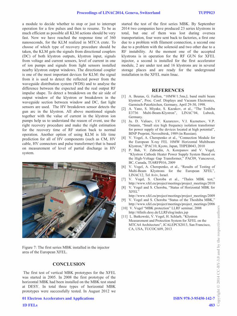
Figure 7: The first series MBK installed in the injector area of the European XFEL.
CONCLUSION
The first test of vertical MBK prototypes for the XFEL was started in 2005. In 2008 the first prototype of the horizontal MBK had been installed on the MBK test stand at DESY. In total three types of horizontal MBK prototypes were successfully tested. In August 2012 we
started the test of the first series MBK. By September 2014 two companies have produced 23 series klystrons in total, but one of them was lost during oversea transportation, four were sent back to factories, a first one due to a problem with filament connection, a second one due to a problem with the solenoid and two other due to a RF instability. At the moment one of the accepted klystrons is in operation for the RF GUN for XFEL injector, a second is installed for the first accelerator module, 2 are under test and 16 klystrons are in several storage places and are ready for the underground installation in the XFEL main linac.
REFERENCES [1] A. Beunas, G. Faillon, “10MW/1.5ms,L band multi beam
klystron”, Proc. Conf. Displays and Vacuum Electronics, Garmisch-Paterkirchen, Germany, April 29-30, 1998.
[2] A. Yano, S. Miyake, S. Kazakov, et al., “The Toshiba E3736 Multi-Beam-Klystron”, LINAC’04, Lubeck, Germany.
[3] Ju. D. Valiaev, I.V. Kazarezov, V.I. Kuznetsov, V.P. Ostanin, “Small size high frequency isolation transformer for power supply of the devices located at high potential”, BINP Preprint, Novosibirsk, 1989 (in Russian).
[4] V. Vogel, A. Cherepenko et al., “Connection Module for the European X-ray FEL 10MW Horizontal Multibeam Klystron,” IPAC10, Kyoto, Japan, THPEB043, 2010
[5] P. Bak, V. Zabrodin, A. Korepanov and V. Vogel, “Klystron Cathode Heater Power Supply System Based on the High-Voltage Gap Transformer,” PAC09, Vancouver, BC, Canada, TU6RFP016, 2009
[6] V. Vogel, A. Cherepenko, et al., “Results of Testing of Multi-Beam Klystrons for the European XFEL”, LINAC12, Tel Aviv, Israel.
[7] V. Vogel, S. Choroba et al., “Thales MBK test,” http://www.xfel.eu/project/meetings/project_meetings/2010
[8] V. Vogel and S. Choroba, “Status of Horizontal MBK for XFEL” http://www.xfel.eu/project/meetings/project_meetings/2009
[9] V. Vogel and S. Choroba “Status of the Thoshiba MBK,” http://www.xfel.eu/project/meetings/project_meetings/2006
[10] V. Vogel “MBK protection” LLRF seminar, 2008 http://ttfinfo.desy.de/LLRFelog/index.jsp
[11] L. Butkowski, V. Vogel, H. Schlarb, “Klystron Measurement and Protection System for XFEL on the MTCA4 Architecture”, ICALEPCS2013, San Francisco, CA, USA, TUCOCA09, 2013
Proceedings of LINAC2014, Geneva, Switzerland TUPP023
01 Electron Accelerators and Applications
1D FELs
ISBN 978-3-95450-142-7
483 Cop
yrig
ht©
2014
CC
-BY-
3.0
and
byth
ere
spec
tive
auth
ors