Test Tracks - Millbrook · the test tracks. We put safety and confidentiality at the heart of our...
52
www.millbrook.co.uk Test Tracks
Transcript of Test Tracks - Millbrook · the test tracks. We put safety and confidentiality at the heart of our...

www.millbrook.co.uk
Test Tracks
2

3
In this brochure, you will find details of our test tracks, from the famous Hill Route at Millbrook to the extraordinary indoor natural snow tracks at Test World. We have also included an overview of the broad range of services and test facilities that we offer to our customers that complement the test tracks. We put safety and confidentiality at the heart of our operations and we are passionate about providing outstanding customer service at all times. We invest in our people and our facilities and strive to be the best service provider in the markets we serve.
All of our employees take pride in delivering exactly what their customers want, whether that is a vehicle test, engineered conversion or smooth-running conference. The quality of our work is reflected in our ISO 9001 and ISO 14001 certifications and ISO 17025 accreditation for many test procedures.
Please do not hesitate to contact us if we can be of service.
Alex Burns President
Welcome to Millbrook
Millbrook Group Overview
Support Services
Test Tracks UK
On-Road Tracks and Features
Off-Road Tracks and Features
Off-Road Technical Features
Customisable Features
Track Permits
Test World
Contents
4
6
8
10
26
29
43
43
44
At Millbrook Group, we are fortunate to have outstanding test tracks in two wonderful locations in the UK and Finland. From these, we serve the best Companies in the World and we help them to develop the vehicles, tyres, engines and fuels of the future. We are independent and impartial in everything that we do.
4
Defence
Security
Bus, Truck and Off Highway
Automotive
Fuels and Lubricants
Markets
Tyres
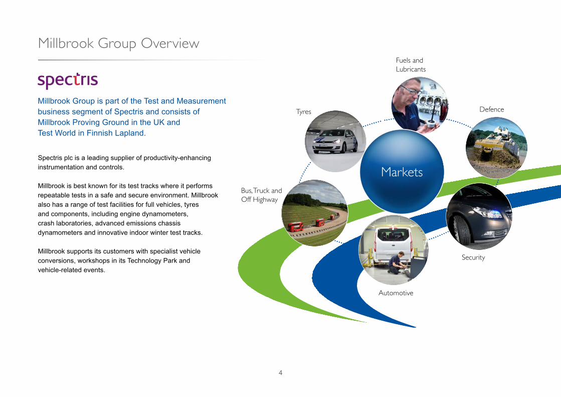
Millbrook Group Overview
Millbrook Group is part of the Test and Measurement business segment of Spectris and consists of Millbrook Proving Ground in the UK and Test World in Finnish Lapland.
Spectris plc is a leading supplier of productivity-enhancing instrumentation and controls.
Millbrook is best known for its test tracks where it performs repeatable tests in a safe and secure environment. Millbrook also has a range of test facilities for full vehicles, tyres and components, including engine dynamometers, crash laboratories, advanced emissions chassis dynamometers and innovative indoor winter test tracks.
Millbrook supports its customers with specialist vehicle conversions, workshops in its Technology Park and vehicle-related events.

5
PowertrainTesting
Special Vehicles
SafetyTesting
Technology Cluster
Vehicle Testing
Services
Compliance
Tyre Testing
Safety and Confidentiality
Investment
TechnicalExcellence
Customer Service
Priorities

6
Millbrook offers its customers a wide range of support services to make tests run as efficiently as possible.
Support Services
Fuels and LubricantsFuels stocked on-site include:• 95 RON Unleaded• 97 RON Unleaded
Other fuels can be made available upon request.
Electric ChargersThere are chargers on site to suit different vehicles. Email: [email protected] or call +44 1525 404 242
Workshop, Office and Conference Room Hire• Separate secure workshops and offices for short
or long periods• Conference and meeting rooms• Workshop support
Support Services• Photography: stills and video• Vehicle loading and load hire• Temporary staff through local accredited suppliers• Transport: people and materials• Waste disposal: domestic rubbish to whole vehicles
• Diesel• LPG

7
Catering• The Millbrook Staff Restaurant is open to visitors• Full catering available in offices and meeting rooms Driver TrainingMillbrook offers driver training packages in a range of disciplines, including:• Advanced driver training
• Limit and beyond-limit handling• Accident avoidance• Anti-hijack• Other specialist training techniques
• Skid control and hazard awareness• Theory and practical with the use of skid cars
• Off-Road driving techniques using world class track facilities
• Trailer training – theory and practical
All courses are structured to meet individual needs.
Corporate EventsMillbrook’s event venues are perfectly suited to product launches, hospitality events, conferences, exhibitions, ride and drive events and themed events on any scale.
For further information please visit www.millbrookvenues.co.uk
Filming, Video and Photo ShootsMillbrook provides a great location for photo shoots and filming vehicles in action.
Filming, Video and Photo ShootsMillbrook provides a great location for photo shoots and filming vehicles in action.

8
14
8
19
42
1
12
5
9
11
3
7
5
6
20
10
15
16
13
21
18
17
22
4645
23 44–
48 51–
47
9
9
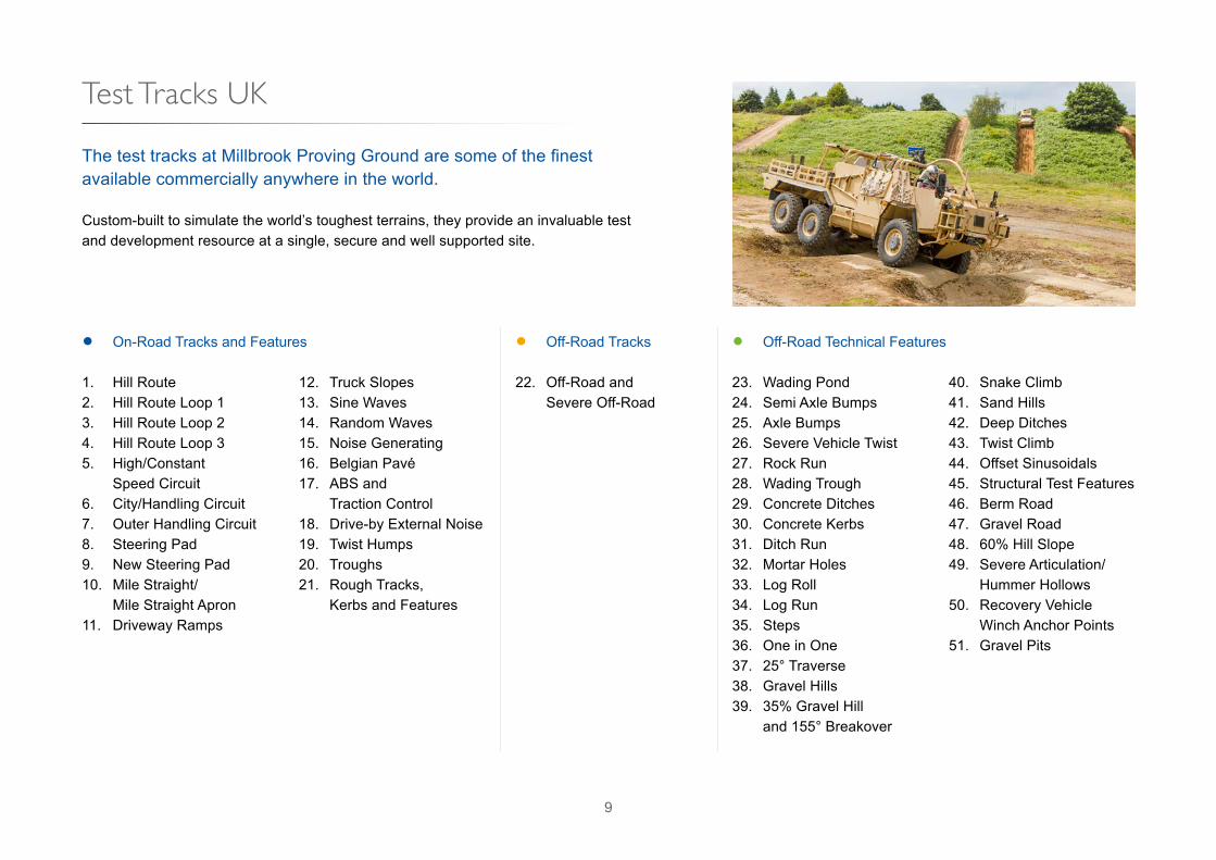
Custom-built to simulate the world’s toughest terrains, they provide an invaluable test and development resource at a single, secure and well supported site.
The test tracks at Millbrook Proving Ground are some of the finest available commercially anywhere in the world.
1. Hill Route2. Hill Route Loop 13. Hill Route Loop 24. Hill Route Loop 35. High/Constant Speed Circuit6. City/Handling Circuit7. Outer Handling Circuit8. Steering Pad9. New Steering Pad 10. Mile Straight/ Mile Straight Apron11. Driveway Ramps
12. Truck Slopes13. Sine Waves14. Random Waves15. Noise Generating16. Belgian Pavé17. ABS and Traction Control18. Drive-by External Noise19. Twist Humps20. Troughs21. Rough Tracks, Kerbs and Features
23. Wading Pond24. Semi Axle Bumps25. Axle Bumps26. Severe Vehicle Twist27. Rock Run28. Wading Trough29. Concrete Ditches30. Concrete Kerbs31. Ditch Run32. Mortar Holes33. Log Roll34. Log Run35. Steps36. One in One37. 25° Traverse38. Gravel Hills39. 35% Gravel Hill and 155° Breakover
40. Snake Climb41. Sand Hills42. Deep Ditches43. Twist Climb44. Offset Sinusoidals45. Structural Test Features46. Berm Road47. Gravel Road48. 60% Hill Slope49. Severe Articulation/ Hummer Hollows50. Recovery Vehicle Winch Anchor Points51. Gravel Pits
• On-Road Tracks and Features • Off-Road Tracks
22. Off-Road and Severe Off-Road
• Off-Road Technical Features
Test Tracks UK
10
On-Road Tracks and Features
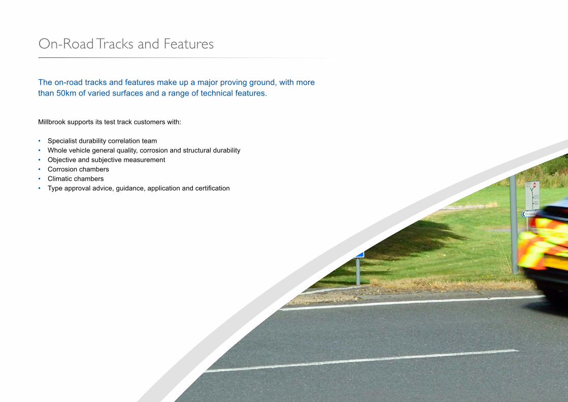
Millbrook supports its test track customers with:
• Specialist durability correlation team• Whole vehicle general quality, corrosion and structural durability• Objective and subjective measurement• Corrosion chambers• Climatic chambers• Type approval advice, guidance, application and certification
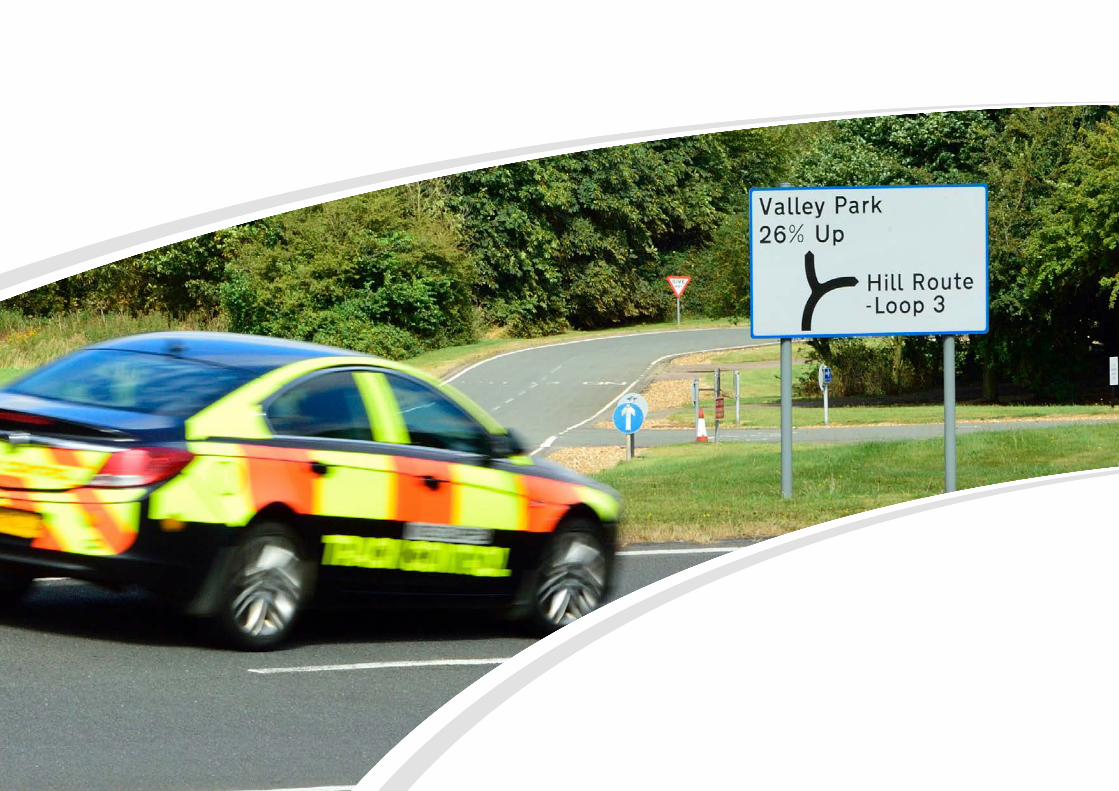
The on-road tracks and features make up a major proving ground, with more than 50km of varied surfaces and a range of technical features.
Image to be confirmed. Email from Steve with images sent Monday 22 August.
11

12
A unique facility for the evaluation of powertrains, transmissions, dynamics, braking and active systems.
• Tarmac road surface 6m wide with flush kerbs/Armco as required• Nominally one way• Total length of circuit 6.5km• Gradients from 6.5% to 26%
1. Hill Route Loop 1
Loop 2
Loop 3

13
• One way facility• Tarmac road surface 6m wide with flush kerbs• Total length of circuit 2.69km
2. Hill Route – Loop 1
2a. Laybys and Bus stops2b. Start of down slope (6.5% for 100m)2c. Start of up slope (7.2% for 870m)2d. Transmission ridges (8 @ 15m CRS)2e. 7.2% Layby2f. Transmission ridges (9 @ 15m CRS)
2g. End 7.2% up2h. Laybys and Bus stop2i. Start of down slope (6.7% for 320m)2j. End of 6.7%2k. Access to Loop 22l. Access to Loop 3
a
e
b
c
d
fg
h
i
j
k
Island A
7.2% Up
6.7% Down
Valley Park
Driveway Ramps
Rough Track and Abuse
6.5% Down
l

14
• One way facility• Tarmac road surface
6m wide with flush kerbs• Total length of circuit
655m
3. Hill Route – Loop 2
3a. Start of down slope (120m, 9m fall)3b. Start of up slope (200m, 22m rise 11.6% for 130m)3c. Start of down slope (225m, 22m fall 11.6% for 150m)3d. Reversing bay (11.6% for 60m)3e. Start of up slope (120m 9m rise)3f. 11.6% Return
• One way facility except 26%
• Tarmac road surface 6m wide with flush kerbs
• Longest circuit length 1.29km
• Total length of circuit 2.99km
4. Hill Route – Loop 3
4a. Start of up slope (250m, 28m rise 14% for 130m)4b. 21% Bypass road4c. Start of down slope (105m, 11m fall)4d. Start of up slope (240m, 42m rise 21% for 170m)4e. Layby4f. Start of down slope (350m, 52m fall 21% for 100m) and (14% Steady 85m)4g. Start of up slope (145m, 8.5m rise 14%)4h. Start of down slope (135m, 16.5m fall 14% for 110m)4i. Start of down slope (200m, 18m fall 17% for 50m)4j. Start of up slope (110m, 15m rise 17% for 45m)4k. Start of down slope (140m, 26m fall 26% for 95m)
a
b
c
d
e
f
a
e
b
c
d
f
g
h
i
jk
11.6% Up
11.6% Down
21% Up
14% Up17% Up
21% Down
14% Down
17% Down
14% Down
26%
15
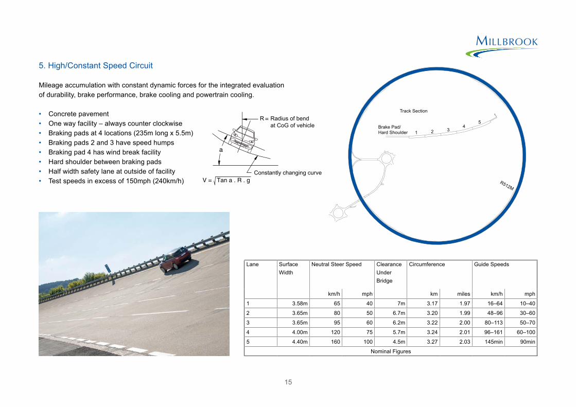
Mileage accumulation with constant dynamic forces for the integrated evaluation of durability, brake performance, brake cooling and powertrain cooling.
• Concrete pavement• One way facility – always counter clockwise• Braking pads at 4 locations (235m long x 5.5m)• Braking pads 2 and 3 have speed humps• Braking pad 4 has wind break facility• Hard shoulder between braking pads• Half width safety lane at outside of facility• Test speeds in excess of 150mph (240km/h)
5. High/Constant Speed Circuit
Radius of bendat CoG of vehicle
Constantly changing curve
R
Lane Surface Width
Neutral Steer Speed Clearance Under Bridge
Circumference Guide Speeds
km/h mph km miles km/h mph
1 3.58m 65 40 7m 3.17 1.97 16–64 10–40
2 3.65m 80 50 6.7m 3.20 1.99 48–96 30–60
3 3.65m 95 60 6.2m 3.22 2.00 80–113 50–70
4 4.00m 120 75 5.7m 3.24 2.01 96–161 60–100
5 4.40m 160 100 4.5m 3.27 2.03 145min 90min
Nominal Figures
Track Section
Brake Pad/Hard Shoulder 1 2 3
45
R512M

16
Customisable city simulation facility.
• One way facility• Total length of circuit 1.2km• Tarmac pavement min 6m wide• Various markings for city driving emulation
6. City/Handling Circuit
6a. Reversing bays6b. Variable troughs/hump profiles6c. Hump6d. Parking bays
• One way facility• Concrete pavement 6m wide with
varying camber (including negative)• Total length of circuit 1.39km
7. Outer Handling Circuit
a
b
c
d
Island B
Island B

17
Exceptionally large circular surface, suitable for applications that require uninterrupted space and customisable features. 50m radius can be wetted using a central sprinkler system.
8a. 137m diameter concrete pad with nominal 1 in 80 fall to centre for drainage8b. Air bag/suspension abuse kerbs/ramps8c. Hardstanding (asphalt)8d. Access roads8e. Sprinkler system
8. Steering Pad
A circular surface, suitable for applications that require uninterrupted space and customisable features.
9a. 125m diameter tarmac pad with nominal 1% gradient for drainage
9. New Steering Pad
a
b
c
d
e
d
Island B
*Available late 2017
a
18
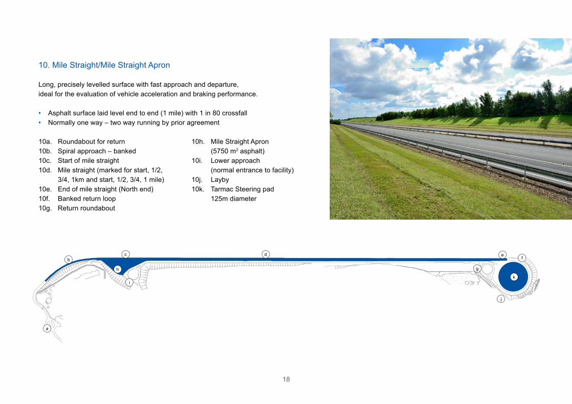
Long, precisely levelled surface with fast approach and departure, ideal for the evaluation of vehicle acceleration and braking performance.
• Asphalt surface laid level end to end (1 mile) with 1 in 80 crossfall• Normally one way – two way running by prior agreement
10. Mile Straight/Mile Straight Apron
10a. Roundabout for return10b. Spiral approach – banked10c. Start of mile straight10d. Mile straight (marked for start, 1/2, 3/4, 1km and start, 1/2, 3/4, 1 mile)10e. End of mile straight (North end)10f. Banked return loop10g. Return roundabout
10h. Mile Straight Apron (5750 m2 asphalt)10i. Lower approach (normal entrance to facility)10j. Layby10k. Tarmac Steering pad 125m diameter
a
bc d e
f
gh
i
j
k

19
Structural twist testing for passenger cars and light trucks.
11. Driveway Ramps
• Concrete construction• Ramp c has radiused inflection points
(dimensions are nominal on centre line)
11a. 16º + 8º11b. 12º + 4.5º11c. 0º + 12º
Evaluation of extreme hill capability including winch performance, suitable for all classes of vehicle including large military and off-highway.
12. Truck Slopes
12a. 20% sine slope (80m, 2 way 6m concrete pavement)12b. 25% sine slope (66m, 2 way 6m concrete pavement) with split friction rollers12c. Split friction rollers12d. Winch anchor post12e. Gravel (25m, 12% loose surface)12f. Reverse dock barrier
a
bc
d
e
f
a
bc

20
Varying pitch and amplitude Sine Waves, both in and out of phase, for high frequency input to vehicle interior and structure.
• Concrete waves of differing amplitude and pitch• Low and medium have 50% out of phase strip
13. Sine Waves
Pitch
Amplitude
Facility Length
High 610mm 50.8mm 91.45m
Medium 915mm 12.5mm 91.45m
Low 305mm 6.5mm 91.45m
Undulating surface, both in and out of phase, inducing maximum suspension travel and high amplitude low frequency input to vehicle structure.
14a. Concrete pavement 3m wide laid to ‘random’ inclinations. 50% out of phase strip (length 738m)
14. Random Waves
a
Low Medium High

21
Range of surfaces and constructions to generate interior noise for vehicle refinement purposes.
15. Noise Generating
15a. Concrete pavement with transverse sawcuts (9mm x 3mm deep @ 28mm CRS – 90m x 2.1m width)15b. Chipping surface – Large granite chippings set in concrete pavement (228m x 2.1m width)15c. Strip of cat’s eyes (44 cat’s eyes along 90m length)15d. Strip of ‘chipping surface’ (one wheel, 0.6m wide and 152m long)
15e.1. Smooth asphalt2. Coarse asphalt
15f .3. Stud damaged concrete4. Cross grooved concrete5. Anti-skid patches
a b
c d
e f
1
2
1
2
3
4
3
4
5

22
Fast evaluation of NVH, durability and vehicle structures using an industry-standard surface.
16. Belgian Pavé
16a. Start of Belgian Pavé16b. 61.0m radius bend, 7.5º bank16c. 47.5m radius bend, 10º bank16d. 47.5m radius bend, 10º bank16e. 47.5m radius bend, 10º bank
16f. 61.0m radius bend, 7.5º bank16g. End of Belgian Pavé. Shallow water trough for damper cooling16h. Layby
• One way facility• 1.45km of engineered block paving• Total length of circuit 1.52km• Pavement width 6m• Straight section laid ‘rough’ with cross
ditches and random depressions• Bends banked and laid ‘smooth’
Wet surface with split capability for the calibration and evaluation of primary safety systems.
• 78m of wetted checkerboard, polished concrete and rough surface
• Total length of circuit 640m
17. ABS and Traction Control
a
b
c
d
e
f
h
g

23
Noise measurement to international standards.
18. Drive-by External Noise
• Asphalt surface to ISO 10844:2014• Return loops each end• Secluded and exclusive location, with nominal
ambient sound pressure levels of 36 dB(A)• Compliant to ISO 10844:2014 Test track specifications
for measuring noise emitted by road vehicles and their tyres
• Compliance includes geometric dimensions and sound absorption characteristics
• Total length of noise surface 26m
19. Twist Humps
Torsional chassis inputs for the development of vehicle structures and corrosion protection.
• Series of 10 handed angled humps (tarmac construction)
• Each hump 4.6m length 140mm high
24
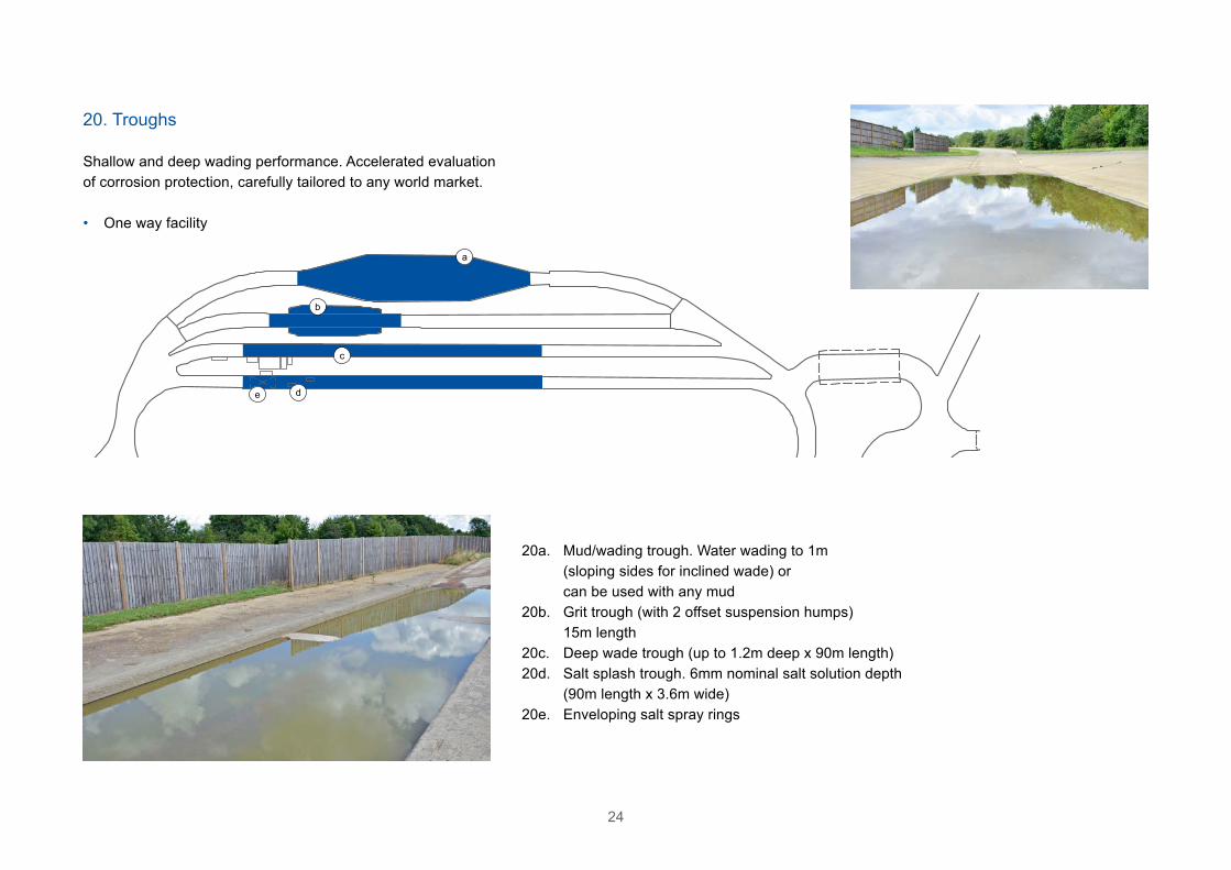
Shallow and deep wading performance. Accelerated evaluation of corrosion protection, carefully tailored to any world market.
• One way facility
20. Troughs
20a. Mud/wading trough. Water wading to 1m (sloping sides for inclined wade) or can be used with any mud20b. Grit trough (with 2 offset suspension humps) 15m length20c. Deep wade trough (up to 1.2m deep x 90m length)20d. Salt splash trough. 6mm nominal salt solution depth (90m length x 3.6m wide)20e. Enveloping salt spray rings
a
b
c
de

25
Suspension and structural evaluation for large, specialist vehicles.
• Generally of tarmac construction with features in concrete
• Total length of circuit 674m
21. Rough Tracks, Kerbs and Features
21a. Truck rough track (2 @ 167m, 230 square blocks 25/50mm projection)21b. Military setts (73m, 230mm x 1220mm blocks projecting 50mm)21c. Maximum pothole21d. Kerbs (100mm, 30º, 45º and 90º)21e. Anchor plates for kerbs/abuse21f. Anchor plates/pits for kerbs/abuse21g. 150mm kerb21h. 100mm kerb21i. Potholes (100mm and 120mm)21j. Concrete Steps – Calibrated 90º steps: 7.5m x 0.35m, 0.5m, 0.75m, 1.0m21k. Gap Crossing – Variable gap ditch crossing: 1.0m – 3.0m in 0.2m steps
a
b
cdef
i
ij
k
hg
a

26
Off-Road Tracks and Features
A range of man-made obstacles, such as axle articulation humps and the sand pit area perfectly compliment the natural terrain of long challenging hills through to tight twisty tracks, recreating every type of environment.
Particular surfaces and features can be generated to suit customers’ needs.
Set in 100 acres of hilly countryside, the Millbrook off-road tracks provide a comprehensive range of terrains for every type of vehicle from soft-roaders to full high-mobility military-specification vehicles.

27
28
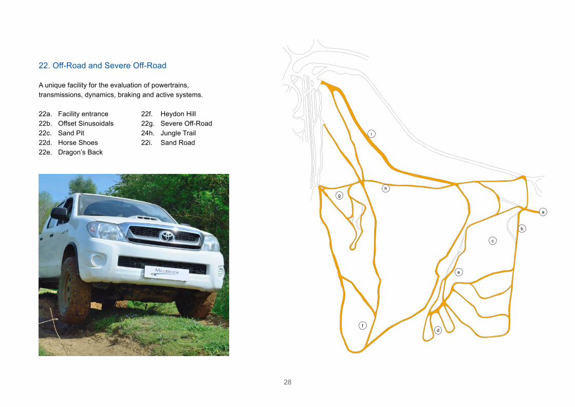
A unique facility for the evaluation of powertrains, transmissions, dynamics, braking and active systems.
22. Off-Road and Severe Off-Road
22a. Facility entrance22b. Offset Sinusoidals22c. Sand Pit22d. Horse Shoes22e. Dragon’s Back
22f. Heydon Hill22g. Severe Off-Road24h. Jungle Trail22i. Sand Road
a
b
c
d
e
f
gh
i

29
Off-Road Technical Features
23. Wading Pond24. Semi-Axle Bumps25. Axle Bumps26. Severe Vehicle Twist27. Rock Run28. Wading Trough29. Concrete Ditches30. Concrete Kerbs31. Ditch Run32. Mortar Holes33. Log Roll34. Log Run35. Steps
36. One in One (45º)37. 25º Traverse38. Gravel Hills39. 35% Gravel Hill and
155º Breakover40. Snake Climb41. Sand Hills42. Deep Ditches43. Twist Climb44. Offset Sinusoidals45. Structural Test Features
(see main map)46. Berm Road
47. Gravel Road (see main map)
48. 60% Hill (Concrete) Slope
49. Severe Articulation/Hummer Hollows
50. Recovery Vehicle Winch Anchors
51. Gravel Pits (see main map)
23
24
25 26
27
2829
30
31
32
33
3435
3637
38
39
40
41
41
43
44
46
48
49
50
38
42

30
23. Wading Pond
A substantial facility for understanding in-water performance.
• Length 26m at depth• Width 8m at depth
• Maximum depth 0.75m• Variable depth
Semi-Axle Bumps
Axle Bumps
Road level
Road ridges for the evaluation of suspension refinement and durability across either or both vehicle sides.
• 5 LH and 5 RH concrete bumps• 50mm high x 125mm projection• Hardcore road
24. Semi-Axle Bumps
Road ridges for the evaluation of suspension refinement and durability across both vehicle sides.
25. Axle Bumps
• 4 full width 3m bumps• 50mm high x 125mm projection• Hardcore road
• Two entrances
31
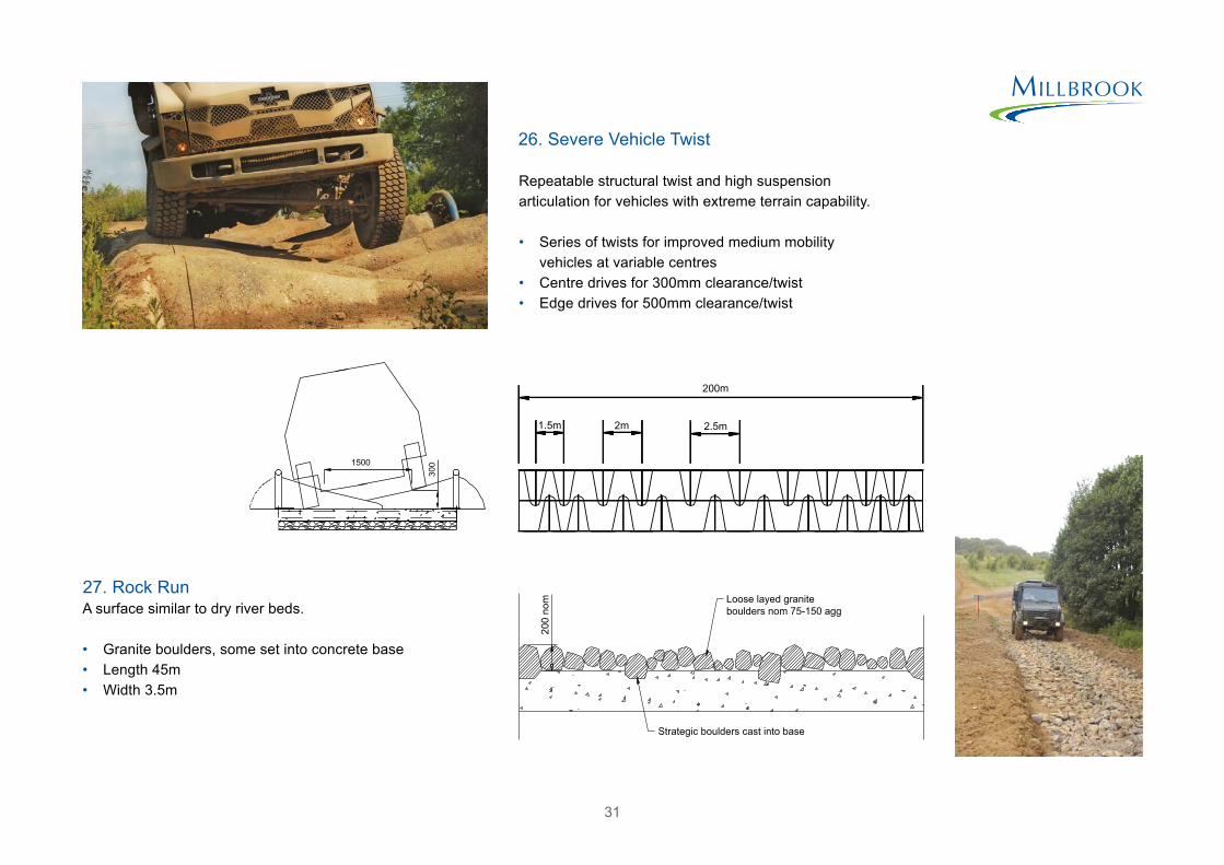
A surface similar to dry river beds.
• Granite boulders, some set into concrete base• Length 45m• Width 3.5m
27. Rock Run
Repeatable structural twist and high suspension articulation for vehicles with extreme terrain capability.
• Series of twists for improved medium mobility vehicles at variable centres
• Centre drives for 300mm clearance/twist• Edge drives for 500mm clearance/twist
26. Severe Vehicle Twist

32
Amphibious vehicle landing simulation with variable depth.
28. Wading Trough
• Landing craft simulation• Length 20.5m at depth• Width 4m
• Maximum depth 1.5m• 23º approach angle
Repeatable simulation of extreme damaged surfaces, ideal for providing severe suspension inputs.
• Tapered profile• Ditch length 7m• Profile width (1m – 1.85m)• Profile depth (290mm – 550mm)
29. Concrete Ditches
• Height 150mm• Trapesoidal profile 900mm base and
350mm apex x 150mm high• 14m long (variable angle approach)
30. Concrete Kerbs
33
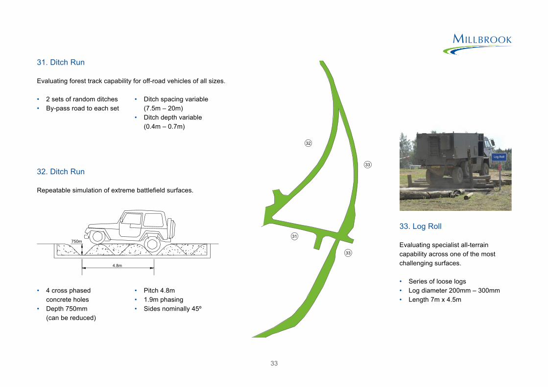
Evaluating forest track capability for off-road vehicles of all sizes.
31. Ditch Run
Repeatable simulation of extreme battlefield surfaces.
32. Ditch Run
Evaluating specialist all-terrain capability across one of the most challenging surfaces.
• Series of loose logs• Log diameter 200mm – 300mm• Length 7m x 4.5m
33. Log Roll
• 2 sets of random ditches• By-pass road to each set
• Ditch spacing variable (7.5m – 20m)
• Ditch depth variable (0.4m – 0.7m)
• 4 cross phased concrete holes
• Depth 750mm (can be reduced)
• Pitch 4.8m• 1.9m phasing• Sides nominally 45º
32
33
31
33
34
Repeatable low frequency inputs.
• Asynchronous undulating
34. Log Run
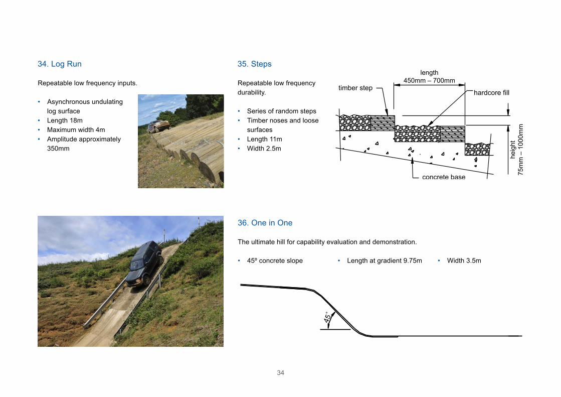
Repeatable low frequency durability.
• Series of random steps• Timber noses and loose
surfaces• Length 11m• Width 2.5m
35. Steps
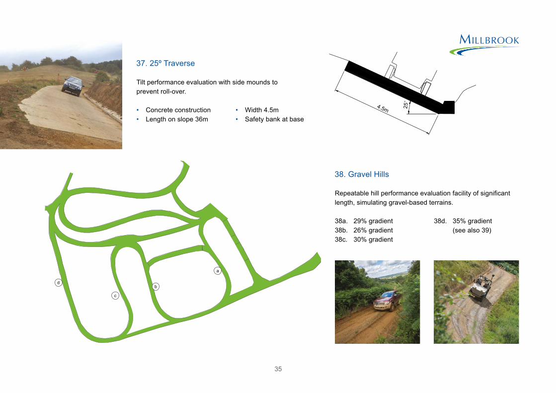
The ultimate hill for capability evaluation and demonstration.
36. One in One
• 45º concrete slope • Length at gradient 9.75m • Width 3.5m
length450mm – 700mm
heig
ht75
mm
– 1
000m
m
log surface• Length 18m• Maximum width 4m• Amplitude approximately
350mm
35
Repeatable hill performance evaluation facility of significant length, simulating gravel-based terrains.
38. Gravel Hills
38a. 29% gradient38b. 26% gradient38c. 30% gradient
38d. 35% gradient (see also 39)
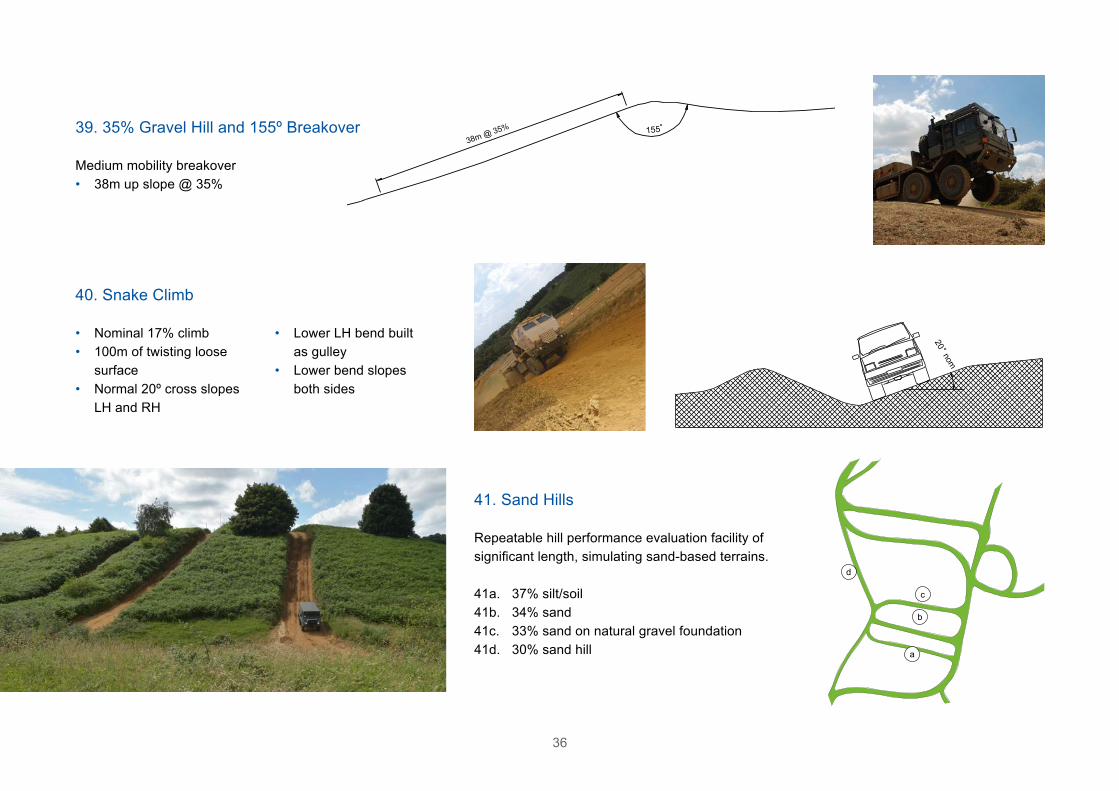
Tilt performance evaluation with side mounds to prevent roll-over.
37. 25º Traverse
• Concrete construction• Length on slope 36m
• Width 4.5m• Safety bank at base
4.5m
a
b
c
d
36
Medium mobility breakover• 38m up slope @ 35%
39. 35% Gravel Hill and 155º Breakover
• Nominal 17% climb• 100m of twisting loose
surface• Normal 20º cross slopes
LH and RH
• Lower LH bend built as gulley
• Lower bend slopes both sides
40. Snake Climb
Repeatable hill performance evaluation facility of significant length, simulating sand-based terrains.
41. Sand Hills
41a. 37% silt/soil41b. 34% sand41c. 33% sand on natural gravel foundation41d. 30% sand hill
38m @ 35%
a
b
c
d

37
Capability evaluation feature for mud track operations.
• Series of 3 large ditches• Sand/silt surface• Maximum ditch depth 3.5m
42. Deep Ditches
Capability evaluation and whole-vehicle testing during one of the most challenging conditions for high mobility vehicles.
43. Twist Climb
• Short slide slope climb• Clay and silt surface• Vehicle twist approach
and departure
A series of offset humps designed to induce maximum axle articulation for small and medium sized off-road vehicles.
44. Offset Sinusoidals
• Nominal 3m centres • Nominal 0.4m depth

38
Consistent, engineered features to challenge all-terrain capability and accelerate structural testing for extreme conditions.
45. Structural Test Features
45a. Reversing road – 190m long compacted and blinded stone45b. Intermediate twist ditches – 23 engineered opposed 45º concrete ditches in unmade road (316m circuit, 108m ditches)45c. Water holes – 11 nominally sinusoidal ditch profiles with water in base (135m circuit, nominal depth 355mm)
a
b
c
d
e
f
g
h

45d. South trail (275m long x 4.5m nominal unpaved road)45e. Ripple road (275m long series of nominally sinusoidal section humps and ditches in unmade road)45f. North trail (275m long x 4.5m nominal unpaved road)45g. Maximum twist ditches45h. Articulation gauges
39
40
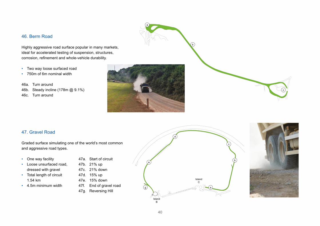
Highly aggressive road surface popular in many markets, ideal for accelerated testing of suspension, structures, corrosion, refinement and whole-vehicle durability.
• Two way loose surfaced road• 750m of 6m nominal width
46. Berm Road
46a. Turn around46b. Steady incline (178m @ 9.1%)46c. Turn around
Graded surface simulating one of the world’s most common and aggressive road types.
47. Gravel Road
47a. Start of circuit47b. 21% up47c. 21% down47d. 15% up47e. 15% down47f. End of gravel road47g. Reversing Hill
• One way facility• Loose unsurfaced road,
dressed with gravel• Total length of circuit
1.54 km• 4.5m minimum width
a
b
c
a
b
c
d
e
f
g
Island C
Island B

41
A calibrated concrete slope used for gradeability, mobility and hill hold brake tests.
• 31 degree slope• 4.5m wide
48. 60% Hill Slope
Offset articulation ditches of varying pitch.
49. Severe Articulation/Hummer Hollows
250mm
1000mm 750mm
1000mm
3750mm
2750mm
1000
1000 up up
A
A
• 40m in length• Maximum 1m deep
100.00102.00104.00106.00108.00110.00112.00114.00116.00
31°
20m
Section A – A
42
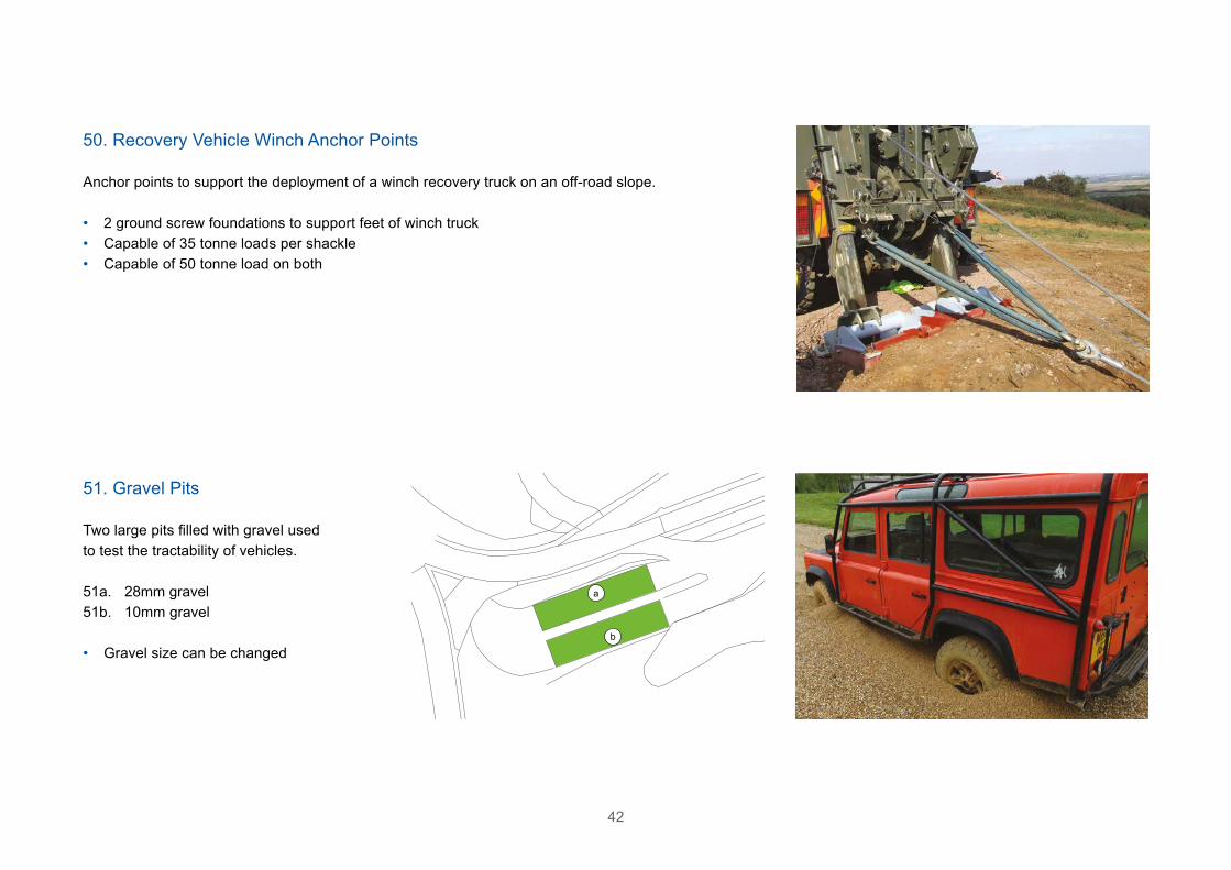
Anchor points to support the deployment of a winch recovery truck on an off-road slope.
• 2 ground screw foundations to support feet of winch truck• Capable of 35 tonne loads per shackle• Capable of 50 tonne load on both
50. Recovery Vehicle Winch Anchor Points
Two large pits filled with gravel used to test the tractability of vehicles.
51a. 28mm gravel51b. 10mm gravel
• Gravel size can be changed
51. Gravel Pits
a
b

43
Working with Millbrook provides access to some of the best commercially available test facilities and expertise anywhere in the World.
Most of the existing features are designed to offer a high level of flexibility and Millbrook has experience of building new features specifically for individual customer projects. Please contact Millbrook to discuss particular requirements.
Customisable Features
Drivers at Millbrook require a valid Track Permit or Access Road Permit as applicable. To obtain a permit please contact Track Control:
Telephone: +44 1525 408 228Email: [email protected]
Track Permits
44
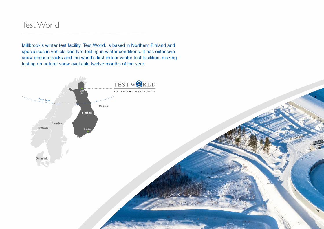
Test World
Millbrook’s winter test facility, Test World, is based in Northern Finland and specialises in vehicle and tyre testing in winter conditions. It has extensive snow and ice tracks and the world’s first indoor winter test facilities, making testing on natural snow available twelve months of the year.
NorwaySweden
Finland
Denmark
Helsinki
Ivalo Arctic Circle
Sweden
Russia

45

46
Year-Round Winter TestingThe World’s most innovative solutions for year-round testing of vehicles and tyres in winter conditions.
Testing on snow and ice For subjective testing, Test World offers a closed-circuit snow handling track measuring 350m x 9m. For objective acceleration and braking work, it offers a snow and ice platform measuring 160m x 16m.
Test World is extending the existing indoor snow and ice platform and adding a second area, giving a maximum combined length of 410m. This will be sufficient to test the largest tyres (C3) used on trucks and buses, as well as to test brakes on passenger cars at higher speeds than possible in the existing facility.
Wet and dry braking, aquaplaning and split friction Two asphalted facilities are being added alongside the snow and ice platforms for performing wet and dry braking and aquaplaning tests, as well as testing traction on split friction surfaces. They will be operated separately or together with a combined length of 410m.
Once construction is finished, the site will provide the majority of objective tests required by tyre manufacturers on one site, year-round.
Indoor facilities enable testing in winter conditions on natural snow and ice. The surfaces are carefully managed to give excellent test results. From spring 2018 three new indoor areas will be available. They will increase the capacity for testing on natural snow and ice and introduce wet and dry braking, aquaplaning and split friction surfaces. The adjustable temperature and humidity will give an advantage to development, certification and labelling testing by allowing greater environmental control.

47
BRAKE 50 m SPLIT 100 m BRAKE 40 m
AQUAPLANING 100 m
1% 1%WET BRAKING 100 m
WATER
ICE
ICE
BRAKE 10 mBRAKE 10 m
SNOW SNOW
SNOW
205 m410 m
SNOW
410 m
Indoor 4 Indoor 3
Indoor 5 Indoor 1
Indoor 2
Customer Area1
Customer Area2
Indoor 1
Indoor 5
Indoor 3
Indoor 4
Indoor 2

48
Mellatracks Proving Ground
Mellatracks Proving Ground is Test World’s main 1,100 hectare site providing a variety of tracks close to workshops and other facilities.
The proving ground is laid out to provide each visiting team with its own garage and set of handling tracks, so maximising test efficiency and confidentiality.
Test World’s team prepares the snow and ice tracks to test anything from the smallest tyres to the largest on-highway vehicles.
Handling Tracks4. Ice Handling 1000 × 6m5. Ice Handling 700 × 6m9. Snow Handling 1200 × 6m21. Snow Handling 1200 × 6m22. Snow Handling 800 × 6m27. Snow Handling 1200 × 6m31. Snow Uphill 900 × 6m32. Snow Uphill 950 × 6m43. Snow Handling 1300 × 6m44. Snow Handling 1300 × 6m45. Snow Handling 1400 × 6m
Flat Tracks1A. Snow Flat 500 × 50m1B. Snow Flat 500 × 50m1C. Ice Flat 500 × 35m2A. Snow Flat 500 × 50m2B. Snow Flat 500 × 50m23. Snow Flat 400 × 40m24. Ice Flat 420 × 20m41. Ice Flat 420 × 20m42. Snow Flat 350 × 40m
Customer Specific Areas51 – 54

49
4
9
21
22
25
27
1A
1B
2A
2B
23
24
41
42
3
6
7
1C
45
43
44
5
31
32
53
51
52
54
61
63
62
Snow Vehicle Dynamics Area High Speed Snow Circuit
Snow Vehicle Handling Track
Other Tracks3. Ice and Snow Circle Ø 50–200m6. Hill Climb 10°7. Snowhill 25°25. Snow Storage for Indoors 61. High Speed Snow Circuit 3120 × 12m62. Snow Vehicle Dynamics Area 380 × 380m63. Snow Vehicle Handling Track 1830 × 10m
Other FacilitiesGarage 1 240m2
Garage 2 110m2
Garage 3 63m2
Garage 4A 215m2
Garage 4B 38m2
Garage 4C 95m2
Garage Indoor 1 83m2
Garage Indoor 2 106m2
Indoor 1 3000m2
Indoor 2 5000m2
Office Indoor 2 44m2
Office 1 80m2
Office 2 30m2
Office 3 35m2
Office 4 48m2
Mellakka Restaurant 50 paxStorage, Cold Chamber 30m2
FuelTest World GarageMaintenance
50
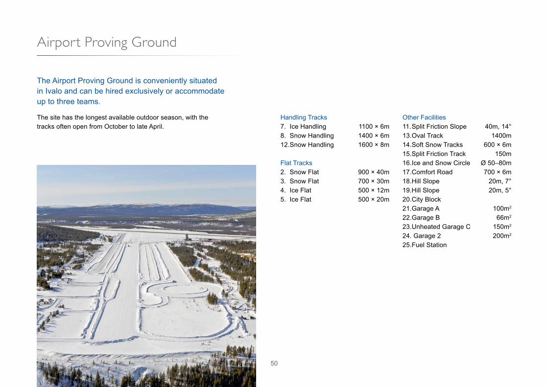
Airport Proving Ground
The Airport Proving Ground is conveniently situated in Ivalo and can be hired exclusively or accommodate up to three teams.
The site has the longest available outdoor season, with the tracks often open from October to late April.
Handling Tracks7. Ice Handling 1100 × 6m8. Snow Handling 1400 × 6m12. Snow Handling 1600 × 8m
Flat Tracks2. Snow Flat 900 × 40m3. Snow Flat 700 × 30m4. Ice Flat 500 × 12m5. Ice Flat 500 × 20m
Other Facilities11. Split Friction Slope 40m, 14°13. Oval Track 1400m14. Soft Snow Tracks 600 × 6m15.Split Friction Track 150m16. Ice and Snow Circle Ø 50–80m17. Comfort Road 700 × 6m18. Hill Slope 20m, 7°19.Hill Slope 20m, 5°20. City Block21. Garage A 100m2
22. Garage B 66m2
23. Unheated Garage C 150m2
24. Garage 2 200m2
25. Fuel Station

51
22 23 21
24
25
8
16
2
2019
18
17
12
14
3
5
13
4
15
11
7

52
In all emergencies, dial 454 (01525 408 454 from an external telephone) which is the internal emergency response call-out telephone number. This is only to be used in emergency situations.
No type of image recording device – including mobile phones with cameras – may be used in any area of the proving ground unless prior authorisation has been given.
Millbrook Group Millbrook, Bedford, MK45 2JQ, UK +44 1525 404 242 [email protected]
www.millbrook.co.uk
2.0