TEST SIMULATION REPORT - Cognitor · COGNITOR Page 1 of 17 TEST SIMULATION REPORT 07X/ 2016 ... IEC...
17
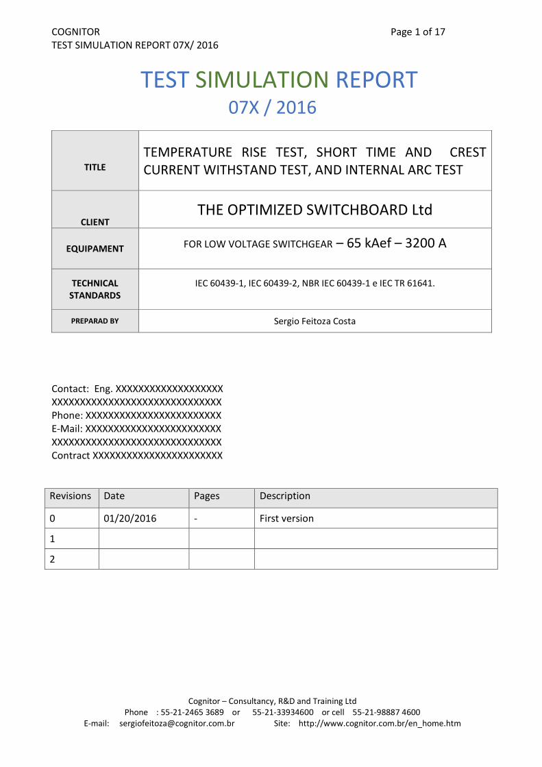
COGNITOR Page 1 of 17 TEST SIMULATION REPORT 07X/ 2016 Cognitor – Consultancy, R&D and Training Ltd Phone : 55-21-2465 3689 or 55-21-33934600 or cell 55-21-98887 4600 E-mail: [email protected] Site: http://www.cognitor.com.br/en_home.htm TEST SIMULATION REPORT 07X / 2016 TITLE TEMPERATURE RISE TEST, SHORT TIME AND CREST CURRENT WITHSTAND TEST, AND INTERNAL ARC TEST CLIENT THE OPTIMIZED SWITCHBOARD Ltd EQUIPAMENT FOR LOW VOLTAGE SWITCHGEAR – 65 kAef – 3200 A TECHNICAL STANDARDS IEC 60439-1, IEC 60439-2, NBR IEC 60439-1 e IEC TR 61641. PREPARAD BY Sergio Feitoza Costa Contact: Eng. XXXXXXXXXXXXXXXXXXX XXXXXXXXXXXXXXXXXXXXXXXXXXXXXX Phone: XXXXXXXXXXXXXXXXXXXXXXXX E-Mail: XXXXXXXXXXXXXXXXXXXXXXXX XXXXXXXXXXXXXXXXXXXXXXXXXXXXXX Contract XXXXXXXXXXXXXXXXXXXXXXX Revisions Date Pages Description 0 01/20/2016 - First version 1 2
-
Upload
duongthuan -
Category
Documents
-
view
237 -
download
3
Transcript of TEST SIMULATION REPORT - Cognitor · COGNITOR Page 1 of 17 TEST SIMULATION REPORT 07X/ 2016 ... IEC...
COGNITOR Page 1 of 17 TEST SIMULATION REPORT 07X/ 2016
Cognitor – Consultancy, R&D and Training Ltd Phone : 55-21-2465 3689 or 55-21-33934600 or cell 55-21-98887 4600
E-mail: [email protected] Site: http://www.cognitor.com.br/en_home.htm
TEST SIMULATION REPORT
07X / 2016
TITLE
TEMPERATURE RISE TEST, SHORT TIME AND CREST CURRENT WITHSTAND TEST, AND INTERNAL ARC TEST
CLIENT THE OPTIMIZED SWITCHBOARD Ltd
EQUIPAMENT FOR LOW VOLTAGE SWITCHGEAR – 65 kAef – 3200 A
TECHNICAL STANDARDS
IEC 60439-1, IEC 60439-2, NBR IEC 60439-1 e IEC TR 61641.
PREPARAD BY Sergio Feitoza Costa
Contact: Eng. XXXXXXXXXXXXXXXXXXX XXXXXXXXXXXXXXXXXXXXXXXXXXXXXX Phone: XXXXXXXXXXXXXXXXXXXXXXXX E-Mail: XXXXXXXXXXXXXXXXXXXXXXXX XXXXXXXXXXXXXXXXXXXXXXXXXXXXXX Contract XXXXXXXXXXXXXXXXXXXXXXX Revisions Date Pages Description
0 01/20/2016 - First version
1
2

COGNITOR Page 2 of 17 TEST SIMULATION REPORT 07X/ 2016
Cognitor – Consultancy, R&D and Training Ltd Phone : 55-21-2465 3689 or 55-21-33934600 or cell 55-21-98887 4600
E-mail: [email protected] Site: http://www.cognitor.com.br/en_home.htm
1) EXECUTIVE RESUME, RESULTS AND CONCLUSIONS.
Simulations were performed to design a low voltage switchboard described in the next sections of this report for the following tests specified in the IEC 61439 and IEC TR 61641 standards.
Temperature rise test with several different currents
Short time and crest current test with 65 kAef – 1,0 s.
Internal arc test 65 kAef – 0,3 s. The methodologies used are described in the articles of Annex A We used three different design options to enable to the client to assess the one that best fits their interests. These options employ bare copper busbar with silver connections without coatings according to Table 1 below. Additional options are possible if requested by the client. In all cases it was considered a panel of 800 (W) x 650 (D) x 2350 (H) mm made from plate # 14 (back cover, side panel, door and ceiling), and # 18 (exit of internal arc gases). Figure 1 shows the dimensions used for the calculation. The options in Table 1 assume that the most limiting aspect to consider, in the present case, is the temperature rise. Aspects of internal arc and electrodynamic forces can be adapted to any of the solutions chosen. With regard to the temperature rise test, it was taken, as reference value, a maximum temperature rise in the connections of 75K (the silver-plated copper bus connections) The possible maximum permanent currents in two situations were calculated: a) No forced ventilation but with a free area of louvers at the bottom with XXX cm2 (completely free air intake and already slaughtered obstructions with filters, etc ...). . The opening for air outlet at the top area must have at least 10% higher than the bottom. b) Same paragraph (a) but with forced ventilation through an exhaust fan or fan to allow an air flow of XXX m3 / h. Considering the passage area for the flow of air as XXX m 2 this would correspond to an average speed of the ascending air XXX / (3600 x 0.52) = 0.XX m / s It was considered that two columns will be tested. Column 1 (input) contains: A main breaker with total power dissipation of 768 W. For example a circuit breaker with resistance by phase 25 µΩ at 3200 A (768 - = 3 x 3200 x 3200A x 25 µΩ). - Around XXXX W of several power dissipation of circuit breakers and other small loads.
COGNITOR Page 3 of 17 TEST SIMULATION REPORT 07X/ 2016
Cognitor – Consultancy, R&D and Training Ltd Phone : 55-21-2465 3689 or 55-21-33934600 or cell 55-21-98887 4600
E-mail: [email protected] Site: http://www.cognitor.com.br/en_home.htm
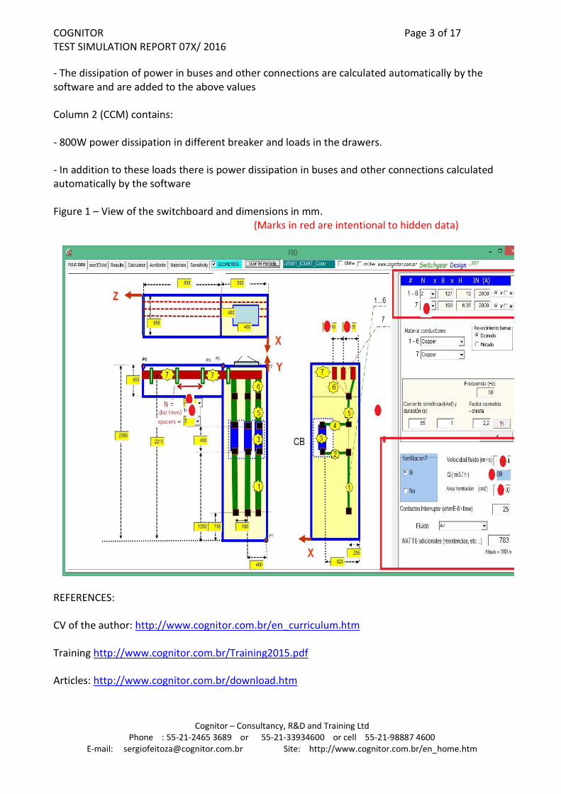
- The dissipation of power in buses and other connections are calculated automatically by the software and are added to the above values Column 2 (CCM) contains: - 800W power dissipation in different breaker and loads in the drawers. - In addition to these loads there is power dissipation in buses and other connections calculated automatically by the software Figure 1 – View of the switchboard and dimensions in mm.
(Marks in red are intentional to hidden data)
REFERENCES: CV of the author: http://www.cognitor.com.br/en_curriculum.htm Training http://www.cognitor.com.br/Training2015.pdf Articles: http://www.cognitor.com.br/download.htm

COGNITOR Page 4 of 17 TEST SIMULATION REPORT 07X/ 2016
Cognitor – Consultancy, R&D and Training Ltd Phone : 55-21-2465 3689 or 55-21-33934600 or cell 55-21-98887 4600
E-mail: [email protected] Site: http://www.cognitor.com.br/en_home.htm
TABLE 1 – DESIGN ALTERNATIVES CONSIDERED (ventilation free open area less than XXX cm2 + additional 10% on top)
Bus bar Design “conventional”
Design VVV 76
Design VVV +T
Vertical column 1 2 x 127x 10 mm 2 x 127x 10 mm 2 x 127x 10 mm
Horizontal common to
columns 1 and 2 XX x 100 x 5 mm
Side by side XX x 100 x 5 mm One over other
XX x 100 x 5 mm One over other
Vertical Column 2 XX x 76 x 6,35 mm XX x 76 x 6,35 mm Bar T 30x20x10 = 500 mm2
Maximum distance L1 (mm) horizontal
XXX mm (1/2 column
width)
XXX mm (column width)
XXX mm (column width)
Maximum distance L2 (mm) vertical
XXX mm
XXX mm
560 mm
Amperes max. without forced ventilation
(Column 1 + horizontal) (Column 2 – vertical)
XXXX A +
XXX A
XXXX A +
XXX A
2500 A +
1000 A
Amperes max. with forced ventilation XXX m3/h
(Column 1 + horizontal) (Column 2 – vertical)
XXXX A
+ XXX A
XXXX A
+ XXX A
3200 A
+ 1500 A

COGNITOR Page 5 of 17 TEST SIMULATION REPORT 07X/ 2016
Cognitor – Consultancy, R&D and Training Ltd Phone : 55-21-2465 3689 or 55-21-33934600 or cell 55-21-98887 4600
E-mail: [email protected] Site: http://www.cognitor.com.br/en_home.htm
“Conventional” Design

COGNITOR Page 6 of 17 TEST SIMULATION REPORT 07X/ 2016
Cognitor – Consultancy, R&D and Training Ltd Phone : 55-21-2465 3689 or 55-21-33934600 or cell 55-21-98887 4600
E-mail: [email protected] Site: http://www.cognitor.com.br/en_home.htm
DESIGN TYPE VVV 76
The photo above is the income column 1 plus the common horizontal bus for columns 1 and 2. Column 2 is similar to the photo for the conventional design
DESIGN TYPE VVV + T

COGNITOR Page 7 of 17 TEST SIMULATION REPORT 07X/ 2016
Cognitor – Consultancy, R&D and Training Ltd Phone : 55-21-2465 3689 or 55-21-33934600 or cell 55-21-98887 4600
E-mail: [email protected] Site: http://www.cognitor.com.br/en_home.htm
COGNITOR Page 8 of 17 TEST SIMULATION REPORT 07X/ 2016
Cognitor – Consultancy, R&D and Training Ltd Phone : 55-21-2465 3689 or 55-21-33934600 or cell 55-21-98887 4600
E-mail: [email protected] Site: http://www.cognitor.com.br/en_home.htm
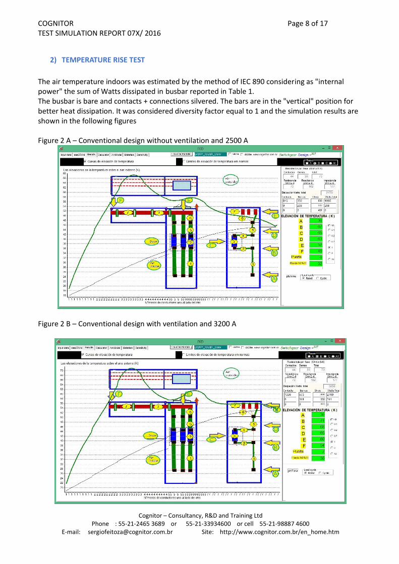
2) TEMPERATURE RISE TEST
The air temperature indoors was estimated by the method of IEC 890 considering as "internal power" the sum of Watts dissipated in busbar reported in Table 1. The busbar is bare and contacts + connections silvered. The bars are in the "vertical" position for better heat dissipation. It was considered diversity factor equal to 1 and the simulation results are shown in the following figures Figure 2 A – Conventional design without ventilation and 2500 A
Figure 2 B – Conventional design with ventilation and 3200 A

COGNITOR Page 9 of 17 TEST SIMULATION REPORT 07X/ 2016
Cognitor – Consultancy, R&D and Training Ltd Phone : 55-21-2465 3689 or 55-21-33934600 or cell 55-21-98887 4600
E-mail: [email protected] Site: http://www.cognitor.com.br/en_home.htm
Figure 2 B – Design VVV 76 without ventilation and 2500 A
Figure 2 B – Design VVV 76 with ventilation and 3200 A

COGNITOR Page 10 of 17 TEST SIMULATION REPORT 07X/ 2016
Cognitor – Consultancy, R&D and Training Ltd Phone : 55-21-2465 3689 or 55-21-33934600 or cell 55-21-98887 4600
E-mail: [email protected] Site: http://www.cognitor.com.br/en_home.htm
Figure 2 C – Design VVV + T without ventilation and 2500 A
Figure 2 C – Design VVV + T with ventilation and 3200 A

COGNITOR Page 11 of 17 TEST SIMULATION REPORT 07X/ 2016
Cognitor – Consultancy, R&D and Training Ltd Phone : 55-21-2465 3689 or 55-21-33934600 or cell 55-21-98887 4600
E-mail: [email protected] Site: http://www.cognitor.com.br/en_home.htm
3) SHORT TIME AND CREST CURRENT WITHSTAND TEST
It was considered a short circuit fed at the bottom of column 1 with the current flowing through the horizontal bus and the short circuit closure point at the bottom of column 2. The values obtained are in Table 1 and Figure 3. For thermal effects of short circuit current it is required a minimum cross section of copper, 403 mm2. The smallest bar cross section is in the vertical bus of column 2 (478 mm2) in the “conventional”. Use grounding bar 1 x 76 x 6.3 mm Figure 3 a - Electrodynamic forces and stresses - horizontal bar + vertical column 2 bar – in conventional and 76 VVV design
COGNITOR Page 12 of 17 TEST SIMULATION REPORT 07X/ 2016
Cognitor – Consultancy, R&D and Training Ltd Phone : 55-21-2465 3689 or 55-21-33934600 or cell 55-21-98887 4600
E-mail: [email protected] Site: http://www.cognitor.com.br/en_home.htm
4) INTERNAL ARC TEST
Low voltage switchboards may be classified, for internal arc, as providing (a) protection of persons and (b) protection to persons and the equipment itself. If (b) it should be able to confine the arc to the "area" where it was started and there can be no arc spread to other "areas". There is a third classification when the equipment is capable of, after an internal arc, operate in a limited way. The arc after starting in a certain place moves in the opposite direction to the voltage source. Throughout its duration, there are effects that may cause impacts to the panel and nearby people. The first effect is the pressure arising from the creation of internal gases. It can damage and open the doors or cause deformation of the walls. The walls are made in a plate thickness (t) and the housing is sealed by screws spaced at distance (L). The envelope withstand mechanical stresses when the thickness of the wall increases. If the distance between the bolts is smaller, the deformation of the plates between each two neighboring bolts will be smaller for a given pressure. The second effect is the "burnthrough". When the arc is in motion can eventually stop at a screw or a metallic barrier. If it stops, the metal material at the point where the arc is touching is melted and vaporized by very high temperatures. The greater the thickness of the shell is a longer duration is necessary to create a hole from which the pressurized hot gases can flow out of the housing. As the arc moves, it causes less damage, because less material is extracted on a specific point. O terceiro efeito é o alcance dos gases quentes e partículas que serão ejetados através dos dispositivos de alívio de pressão. Isto está diretamente relacionado com os valores e duração da sobrepressão. Para painéis de baixa tensão onde, no ensaio de arco interno, não é necessário simular um teto onde os gases poderiam se refletir e queimar os anteparos de algodão este aspecto tem menos importância e não será tratado aqui. Para avaliar estes efeitos estabelecemos alguns “indicadores de desempenho” para permitir estimar se um determinado projeto é aceitável. Os indicadores são mostrados na primeira coluna da Tabela 5. Vamos utilizar o valor de pico da sobrepressão < 90% e a integral da curva sobrepressão x tempo < 60 como critérios principais. We estimate that in some specific points a thickness of at least 5.7 mm steel plate (reinforcement) is required, so that the 65 KAef 65 for 300 ms do not make a hole in the enclosure. The estimated arc speed , in this case, is around 165 m / s. Therefore, as the width of three columns side by side, is 2400 mm arc starts in a right end will come to the opposite end or bottom of the vertical bus in less than 20 ms. As the test lasts 300 ms Let's assume that the arc will be stopped somewhere at the end of the physical path throughout most of the duration of the test. The third effect arc effect is the reach of hot gases and particles that are ejected through the pressure relief devices. This is directly related to the values of pressure and duration. For LV switchboards internal arc test tests, it is not necessary to simulate a ceiling where the gases might reflect. Therefore, this aspect is of less importance and will not be treated here. For MV this is an important aspect.

COGNITOR Page 13 of 17 TEST SIMULATION REPORT 07X/ 2016
Cognitor – Consultancy, R&D and Training Ltd Phone : 55-21-2465 3689 or 55-21-33934600 or cell 55-21-98887 4600
E-mail: [email protected] Site: http://www.cognitor.com.br/en_home.htm
To evaluate these effects we established some "performance indicators" to allow assess whether a project is acceptable. They are in the first column of Table 5. We will use the overpressure peak value <90% and the integral of the pressure versus time curve <60 as the main criteria. RESULTS OF SIMULATIONS FOR INTERNAL ARC TEST The results are in Table 1. These results use the input data in Table 2. Table 3_- Calculated values for prospective current 65 kAef x 300 ms for the 3 design options (assuming that an automatic device closes the ventilation openings and that only overpressure relief windows are active)
Performance indicator Calculated value Acceptable value
Maximum overpressure above the atmospheric ΔP ( % )
60 % < 70 a 90
Duration of the overpressure ( ms) 42 -
Integral of overpressure curve on the time (bar*s*1000)
28 <20 a 60
Time to reach the maximum overpressure 100% ΔP (ms)
20 -
Time to return to 50% ΔP (ms) 35 - Arc voltage (V) 87 -
Arc current (KAef) < Prospective current
53,3 -
COMMENTS ABOUT THE DESIGN AND RECOMMENDATIONS RELATED TO INTERNAL ARC In the construction, a 2.00 mm thick sheet is used except in overpressure relief windows. The arc speed is of the order of 160 m / s and therefore in a time less than 20 ms the arc will reach the far end of the panel, if not before jumping to the plate. One possible point where you can jump on the curve is between the horizontal and the vertical bus. This consultant recommends proceeding as follows regarding the project: - In points near to the "corners" where the arc move from the horizontal to the vertical bus as well as the points where the arc reach the end of its travel (bottom of the vertical bus) to place a reinforcing plate at inner side, so that the total thickness (booster + closing plate) is about 6 mm. - To prevent the arc jump to the plate in the points near the joints of the horizontal buses with vertical take the plate at that point with a plate of insulating material. - Not to put arc barriers to avoid reducing the pressurized volumes. In this way we are increasing
the air communication area between columns and so there will be less pressure.
COGNITOR Page 14 of 17 TEST SIMULATION REPORT 07X/ 2016
Cognitor – Consultancy, R&D and Training Ltd Phone : 55-21-2465 3689 or 55-21-33934600 or cell 55-21-98887 4600
E-mail: [email protected] Site: http://www.cognitor.com.br/en_home.htm
By doing this, we are fitting in the internal arc classification of "protecting the people". At a future time, after success in this classification the client can seek solutions to put the arc barriers and thus be able to get a rating of "protecting the people and the equipment itself" We found that the maximum pressure is below the maximum acceptable limits. The polycarbonate cover of the circuit breaker should generally have the greatest possible thickness (e.g. 6 mm) and shall be placed in metallic reinforcing edges to press the polycarbonate against the metal wall preventing the passage of gases between the polycarbonate and wall. The door locks and hinges need to be reinforced as much as possible using the shortest distance possible between fasteners. It is essential that at least two columns are tested with air interconnection to have the benefit of greater internal volume. The depressurization windows must be as light as possible to open (with small overpressure) but enough fitted to avoid being thrown. The hot gases cannot get out through the front vetilation openings because would burn the cotton indicators Care must be taken in construction so that the locks used in the doors are robust enough to prevent a visible deformation which can open an space for the flow of hot gases from inside to outside. The reduction of arc current due to the arc resistance is considered. The values in Table 5 indicate an arc current of approximately 53.3 KAef instead of 65 KAef (prospective short circuit current at the input panel)
All simulations were performed with the computational tool SwitchgearDesign developed by the author of this report and owned by Cognitor. In the articles listed in Annex A is shown the calculation methodology and examples used to validate the simulations. These articles can be downloaded freely in the download part of Cognitor site http://www.cognitor.com.br/en_home.htm
COGNITOR Page 15 of 17 TEST SIMULATION REPORT 07X/ 2016
Cognitor – Consultancy, R&D and Training Ltd Phone : 55-21-2465 3689 or 55-21-33934600 or cell 55-21-98887 4600
E-mail: [email protected] Site: http://www.cognitor.com.br/en_home.htm
5) Annex A – REFERENCES (ARTICLES AUTHORED OR CO-AUTHORED BY SERGIO FEITOZA
COSTA)
[0] Co-author of the brochure CIGRE 602 / 2014 TOOLS FOR THE SIMULATION OF THE EFFECTS OF THE INTERNAL ARC IN TRANSMISSION AND DISTRIBUTION SWITCHGEAR
http://www.e-cigre.org/Publications/ru_pu.asp [1] Report 074/2014 VALIDATION OF MAGNETIC & ELECTRIC FIELDS MAPPING & TEMPERATURE RISE TESTS SIMULATIONS. http://www.cognitor.com.br/TR074ENGValidationTempRise.pdf [2] Report 071/2014: VALIDATION OF SOFTWARE SWITCHGEARDESIGN_307 FOR SIMULATION OF HIGH POWER TESTS (TEMPERATURE RISE, SHORT TIME AND CREST CURRENT TESTS – ELECTRO DYNAMICAL FORCES / STRESSES AND OVERPRESSURES FROM INTERNAL ARC) http://www.cognitor.com.br/TR_071_ENG_ValidationSwitchgear.pdf [ 3 ] Book “Reference text for the courses SWITCHGEAR, BUSWAYS & ISOLATORS and SUBSTATIONS AND LINES EQUIPMENT” (available also in Spanish and Portuguese in the site) http://www.cognitor.com.br/Book_SE_SW_2013_ENG.pdf [4] A "GUIDE" FOR THE USE OF CALCULATIONS AND SIMULATION OF LABORATORY TESTS FOR INCREASING THE COMPETITIVENESS OF THE ELECTRIC INDUSTRY http://www.cognitor.com.br/Article_Competitivity_Eng_04102011.pdf [ 5 ] “VALIDATION OF SIMULATIONS OF ELECTRODYNAMICAL FORCES, TEMPERATURE-RISE AND INTERNAL ARC TESTS IN SWITCHGEAR (& main parts of a code) (2010) Presented at the CIGRE Technical Seminar "Modeling and Testing of Transmission and Distribution Switchgear" March 24, 2010 Brisbane – Australia Download: http://www.cognitor.com.br/Validation_Simulations_English.pdf [ 6 ] “SIMULATION, IEC STANDARDS AND TESTING LABORATORIES: JOINING THE PIECES FOR HIGHER QUALITY HV EQUIPMENT”. Paper published PS1-06 in the CIGRÈ International Technical Colloquium - Rio de Janeiro - September 2007 http://www.cognitor.com.br/Artigo_Cigre_SergioFeitozaCosta_Cognitor.pdf Published also in in Energy Pulse weekly, September, 28 , 2010 http://www.energypulse.net/centers/article/article_display.cfm?a_id=2338 [ 7 ] “SIMULATIONS AND CALCULATIONS AS VERIFICATION TOOLS FOR DESIGN AND PERFORMANCE OF HIGH-VOLTAGE EQUIPMENT” Co-authors: M. Kriegel, X. Zhu, M. Glinkowski, A. Grund, H.K. Kim, P. Robin-Jouan, L. Van der Sluis, R.P.P. Smeets, T. Uchii, H. Digard, D. Yoshida, S. Feitoza Costa CIGRE WG A3-20 publication A3-210 (2008) - Presented at Congress Cigre - Paris 2008 http://www.cognitor.com.br/Cigre_Paris_A3_210_2008.pdf
COGNITOR Page 16 of 17 TEST SIMULATION REPORT 07X/ 2016
Cognitor – Consultancy, R&D and Training Ltd Phone : 55-21-2465 3689 or 55-21-33934600 or cell 55-21-98887 4600
E-mail: [email protected] Site: http://www.cognitor.com.br/en_home.htm
[ 8 ] SIGNIFICANT PARAMETERS IN INTERNAL ARC SIMULATION AND TESTING, CIGRE WG A3.24, CIGRE A3 SESSION, 2009 Co-authors: M. Kriegel, R. Smeets, N. Uzelac, R. Pater, M. Glinkowski, P. Vinson, S. Feitoza Costa, G. Pietsch, E. Dullni, Th. Reiher, L. van der Sluis, D. Yoshida, H.K. Kim, K. Y. Kweon, E. Fjeld, [ 9 ] Paper FINDING THE OPTIMAL SWITCHGEAR DESIGN: A comparison between aluminum and copper and an idea of new concept. Co-authors: Sergio Feitoza Costa & Marlon Campos Also published in Portuguese in January 2014 in Magazine Revista O SETOR ELÉTRICO “as ALUMINIO X COBRE EN PROYECTOS DE LOS PANELES ELÉCTRICOS (PÁGINA 136) In English : http://www.cognitor.com.br/DesignOptimization.pdf
[10] HOW CAN IEC STANDARDS HELP TO REDUCE THE GAP BETWEEN DEVELOPED COUNTRIES AND OTHER COUNTRIES?
http://www.cognitor.com.br/ProposalToIEC.pdf [ 11 ] VALIDATION OF TEST REPORTS ISSUED BY RECOGNIZED TESTING LABORATORIES http://www.cognitor.com.br/ValidatingReports_Eng.pdf [12 ] SWITCHGEAR , BUSBAR SYSTEMS and ITS BUILT-IN COMPONENTS: SOMETHING IS MISSING IN IEC and IEEE STANDARDS Published in Energy Pulse weekly, September, 28 , 2010 http://www.cognitor.com.br/Switchgear_Busbar_Standards_Review_English.pdf http://www.energypulse.net/centers/article/article_display.cfm?a_id=2338 [16] Free Software DECIDIX SOFTWARE FOR THE TECHNICAL ECONOMYCAL ASSESSMENT OF ENERGY PROJECTS http://www.cognitor.com.br/c_Feasibily_Analysis.htm
17) INDUCING AND ASSESSING NEW TECHNOLOGIES FOR THE ELECTRIC INDUSTRY OF DEVELOPING COUNTRIES
http://www.cognitor.com.br/InducingNewTechnologiesSubstationEN.pdf
In Spanish and In Portuguese: see and download in http://www.cognitor.com.br/download.htm
COGNITOR Page 17 of 17 TEST SIMULATION REPORT 07X/ 2016
Cognitor – Consultancy, R&D and Training Ltd Phone : 55-21-2465 3689 or 55-21-33934600 or cell 55-21-98887 4600
E-mail: [email protected] Site: http://www.cognitor.com.br/en_home.htm
6) Annex B - TECHNICAL STANDARDS OF REFERENCE
[1 ] IEC 62271-200 Ed. 2.0 b:2011 : High-voltage switchgear and controlgear - Part 200: AC metal-enclosed switchgear and controlgear for rated voltages above 1 kV and up to and including 52 kV
[ 2] IEC TR 60890: A Method of Temperature-rise Assessment by Extrapolation for Partially Type-Tested Assemblies (PTTA) of Low-Voltage Switchgear and Controlgear
[ 3] IEC 61117: Method for assessing the short-circuit withstand strength of partially type-tested assemblies (PTTA)
[ 4 ] IEC 60865-1: Short-circuit currents – calculation of effects – Part 1: Definitions and calculation
[ 5] IEC 60865-2: Short-circuit currents – calculation of effects – Part 2: Examples of calculation
[ 6 ] IEC TR 60943: Guidance concerning the permissible temperature rise for parts of electrical equipment, in particular for terminals
[ 7] CIGRE Brochure No. xxx, 2014, “Tools for the simulation of effects of the internal arc in MV and HV switchgear”
[ 8 ] IEC 61439-1 Ed. 2.0 (2011) – Low-voltage switchgear and controlgear assemblies - Part 1: General rules
[ 9 ] IEC 61439-2 Ed. 2.0 (2011) – Low-voltage switchgear and controlgear assemblies - Part 2: Power switchgear and controlgear assemblies
[ 10 ] IEC TR 61641(2008) – Enclosed Low Voltage Switchgear Assemblies – Guide for testing under Conditions of Arcing due to Internal Fault. [ 11] ABB Switchgear Manual - ABB Pocket Book - Switchgear Manual - 10th revised edition Edited by ABB Calor Emag Schaltanlagen AG Mannheim and ABB Calor Emag Mittelspannung GmbH Ratingen - Previous editions: (published till 1987 by BBC Brown Boveri, since 1988 by ABB) - First edition 1948 - http://pt.scribd.com/doc/23692182/ABB-Switchgear-Manual-11th-Ed-2006 [ 12] Sergio Feitoza Costa´s M.Sc. thesis on Electrodynamic Forces at http://www.cognitor.com.br/electrodynamic.pdf COPPE / UFRJ – Janeiro - 1981