Test Report No. SETS2012096 IEC IEC.pdf · Test Report No. SETS2012096 IEC Product: Schneider...
16
The results reported herein have been performed in accordance with the laboratory’s term of accreditation under the Singapore Accreditation Council – Singapore Laboratory Accreditation Scheme. The report shall not be reproduced except in full. Test Report No. SETS2012096 IEC Product: Schneider Electric type E8131L1, E8132L1, E8133L1, E8131L2, E8132L2, E8133L2 10AX 1, 2 & 3 Gang 1 & 2 Way Flush Mounted Switches Clients rating: 10AX, 250V~ Client: Schneider Electric Asia Pacific Ltd. 13/F, East Wing, Warwick House, Taikoo Place, 979 King’s Road, Quarry Bay, Hong Kong Manufacturer: Clipsal Manufacturing (Huizhou) Ltd No. 3 Lejin West Road, Zhongkai Hi-tech Industrial Development Zone, Huizhou, Guang Dong, China Nature of tests: IEC 60669-1:2007 (Edition 3.2) Switches for household and similar fixed-electrical installations – Part 1: General requirements Result: Complied Issued on: 05 th September 2012 Initial distribution: Client (1) SETS file (1) Original 1 Copy Tested by: Authorised Signature: Leong Chun Pong Victor Ang Meng Kok Test Officer Executive Engineer Singapore Electrical Testing Services 97 Pioneer Road, Singapore 639579 Tel (65) 6 861 9118 Fax (65) 6 863 2760 Cert. No: LA-2004-0303-E
Transcript of Test Report No. SETS2012096 IEC IEC.pdf · Test Report No. SETS2012096 IEC Product: Schneider...

The results reported herein have been performed in accordance with the laboratory’s term of accreditation under the Singapore Accreditation Council – Singapore Laboratory Accreditation Scheme. The report shall not be reproduced except in full.
Test Report No. SETS2012096 IEC Product: Schneider Electric type E8131L1, E8132L1, E8133L1, E8131L2, E8132L2, E8133L2 10AX 1, 2 & 3 Gang 1 & 2 Way
Flush Mounted Switches Clients rating: 10AX, 250V~ Client: Schneider Electric Asia Pacific Ltd. 13/F, East Wing, Warwick House, Taikoo Place, 979 King’s Road, Quarry Bay, Hong Kong Manufacturer: Clipsal Manufacturing (Huizhou) Ltd No. 3 Lejin West Road, Zhongkai Hi-tech Industrial Development Zone, Huizhou, Guang Dong, China Nature of tests: IEC 60669-1:2007 (Edition 3.2) Switches for household and similar fixed-electrical installations – Part 1: General requirements Result: Complied Issued on: 05th September 2012 Initial distribution: Client (1) SETS file (1) Original 1 Copy Tested by: Authorised Signature: Leong Chun Pong Victor Ang Meng Kok Test Officer Executive Engineer
Singapore Electrical Testing Services 97 Pioneer Road, Singapore 639579 Tel (65) 6 861 9118 Fax (65) 6 863 2760
Cert. No: LA-2004-0303-E

Test Report No. SETS2012096 IEC
Page 2 of 16
Dates Date of receipt of test item: 11.06.2012, 25.07.2012 & 31.08.2012 Date(s) of performance of test: 14.06.2012 to 27.08.2012 Marking Grid plate - Schneider Electric (Front) Grid plate - Schneider Electric E8131L1 / E8132L1 / E8133L1 (Back) E8131L2 / E8132L2 / E8133L2 10AX 250V~ CCCs GB 16915.1 SS 227-1 IEC 60669-1 MS IEC 60669-1 BS EN 60669-1 Base - 1 Way 2 Way L L1 COM COM L2

Test Report No. SETS2012096 IEC
Page 3 of 16
Notes: 1. Details in testing record file no. SETS2012096 IEC. 2. The brief precis in column 2 provides an indication only of the prime requirements. For further details, refer to the
standard specification(s) and clauses listed in column 1. Column 3 is the selected requirements as appropriate for this product testing.
3. Specifications applied – IEC 60669-1:2007 (Edition 3.2). 4. Estimated uncertainty for measurement of temperature; ± 2°C (95%) (Type K thermocouple). 5. Reporting of results herein is taking into account U of M. Where measurement is on the limit or below the limit it is
deemed to comply. Where measurement is above the limit it is deemed not to comply. 6. This test report is only based on assessment and tests applied to the specific test item submitted by the client at the time
of its testing. 7. SETS shall disclaim any & all responsibility or obligation for:
i) any other item not included in this submission of testing. ii) the later performance of this product.
Specification and
Clause Nos.
Clause Title (Inc. a brief precis of Requirements and Criteria.)
Actual Results, Assessment,
Remarks IEC 60669-1:2007 (Edition 3.2) 4 General requirements Performance of switches in normal use, shall be reliable and without danger to user or
surrounds. Capable of meeting all relevant requirements and tests specified in this standard.
Complied
5 General notes on tests 5.1 Tests according to this standard are type test Complied 5.2 Unless otherwise specified, tested as delivered, under normal conditions of use with
appropriate boxes. Complied
5.3 Unless otherwise specified tested in the order of clauses between 15°C & 35°C. Complied 5.4 Test items tested as follows: Complied 3 test items: Cls. 4 to 19.1 & 20 to 23 3 test items: Cl. 19.2 3 test items: Cls. 24, 25 5.5 If no test items fails in the complete series of tests switches of that type shall be deemed to
comply with this standard. Complied
6 Ratings 6.1 Preferred rates voltages: 130 V, 230 V, 250 V, 277 V, 380 V, 400 V, 415 V and 440 V. 250V 6.2 Preferred rated currents: 6 A, 10 A, 16 A, 20 A, 25 A, 32 A, 40 A, 45 A, 50 A and 63 A.
Switches with a rated current < 16 A, shall have a fluorescent lamp current rating equal to the rated current.
10AX
6.3 Switches shall preferably have a degree of protection IP20, IP40, IP44, IP54 or IP55. IP20 7 Classification 7.1 Switches are classified: 7.1.1 According to possible connections per fig. 8 - No. 1 & 6 7.1.2 According to contact opening and switch performance - Normal gap 7.1.3 Void - 7.1.4 According to degree of protection against harmful ingress of water - IPX0 7.1.5 According to method of actuating the switch - Rocker 7.1.6 According to method of mounting the switch - Flush-type 7.1.7 According to method of installation as a consequence of design - Design B 7.1.8 According to type of terminal - Screw pillar
terminal 7.1.9 According to degree of protection against harmful solid foreign objects - IP2X 7.2 Preferred combinations of no. of poles and ratings per table 1. Complied

Test Report No. SETS2012096 IEC
Page 4 of 16
Specification
and Clause Nos.
Clause Title (Inc. a brief precis of Requirements and Criteria.)
Actual Results, Assessment,
Remarks IEC 60669-1:2007 (Edition 3.2) 8 Markings 8.1 Shall be marked with the following: Complied - Rated current in amperes, followed by “X” for fluorescent loads as applicable. 10AX - Rated voltage in volts. 250V - Symbol for nature of supply. ~ - Makers or vendors name, trade mark or identification mark. Schneider
Electric - Type reference, which maybe a catalogue number. Refer to page 2 - Symbol for mini-gap construction. Not applicable - Symbol for micro gap construction. Not applicable - Symbol for semiconductor switching devices. Not applicable - 1st characteristic numeral degree of protection Not applicable - 2nd characteristic numeral degree of protection Not applicable 8.2 When symbols used they shall be as follows: A or AX for amperes; V for volts; ~ for a.c; N for neutral; for earth; O for off; I for on, m
for mini-gap, µ for micro-gap, ε for without contact gap, IPXX for degree of protection. Nature of supply to be marked next to rated voltage and current.
Complied
8.3 Marking per Cl. 8.1 shall be on the main part of the switch, except IP rating. Complied 8.4 Phase conductor terminals shall be identified, unless self-evident or of no importance. Complied 8.5 Neutral conductor terminals shall be indicated by N.
Earth conductor terminal shall be indicated . Marking shall not be placed on screws or other easily removable part.
Not applicable
8.6 If switches are marked to indicate the switch position, they shall be so marked that the direction of movement of the actuating member to its different positions or the actual position is clearly indicated.
Not applicable
8.7 Push buttons shall be coloured red if it services to open the circuit. Not applicable 8.8 Details required in accompanying instruction sheet if special precautions necessary to
install. Not applicable
8.9 Marking to be durable and easily legible. Durability tested by rubbing by hand for 15 s with cloth soaked with water and again for 15 s with cloth soaked with petroleum spirit, after which marking shall be legible.
Complied
9 Checking of dimensions Switches & boxes shall comply with appropriate standard sheets, if any. Complied 10 Protection against electric shock 10.1 When mounted and correctly wired as in normal use, live parts shall not be accessible.
Checked by inspection and test finger fig. 1 applied when test item fitted with conductors of smallest size per Cl. 12 then repeated fitted with max. size. Switches with thermoplastic covers tested at 35 ± 2°C subjected for 60s to force of 75 N applied through tip of straight unjointed test finger. Force of 10 N applied to knock-outs, during which switches and mounting means shall not deform such that live parts can be touched with unjointed test finger.
Complied
10.2 Knobs, operating members, push buttons, rockers and the like shall be insulating material, unless their accessible metal parts are separated from live parts by double/reinforced insulation or earthed. Compliance checked by inspection and Cls. 16 and 23.
Complied
10.3 Accessible parts of switches rated < 16 A shall be of insulating material except - (a) Small fixing screws and the like, isolated from live parts. (b) Actuating members complying with Cl. 10.2. (c) Metal covers and cover plates complying with Cl. 10.3.1 or Cl. 10.3.2.
Complied
Test Report No. SETS2012096 IEC
Page 5 of 16
Specification
and Clause Nos.
Clause Title (Inc. a brief precis of Requirements and Criteria.)
Actual Results, Assessment,
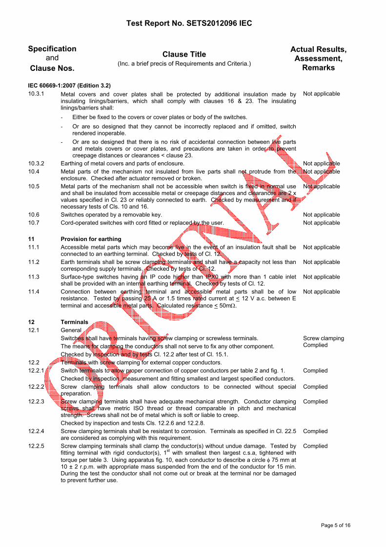
Remarks IEC 60669-1:2007 (Edition 3.2) 10.3.1 Metal covers and cover plates shall be protected by additional insulation made by
insulating linings/barriers, which shall comply with clauses 16 & 23. The insulating linings/barriers shall: - Either be fixed to the covers or cover plates or body of the switches. - Or are so designed that they cannot be incorrectly replaced and if omitted, switch
rendered inoperable. - Or are so designed that there is no risk of accidental connection between live parts
and metals covers or cover plates, and precautions are taken in order to prevent creepage distances or clearances < clause 23.
Not applicable
10.3.2 Earthing of metal covers and parts of enclosure. Not applicable 10.4 Metal parts of the mechanism not insulated from live parts shall not protrude from the
enclosure. Checked after actuator removed or broken. Not applicable
10.5 Metal parts of the mechanism shall not be accessible when switch is fixed in normal use and shall be insulated from accessible metal or creepage distances and clearances are 2 x values specified in Cl. 23 or reliably connected to earth. Checked by measurement and if necessary tests of Cls. 10 and 16.
Not applicable
10.6 Switches operated by a removable key. Not applicable 10.7 Cord-operated switches with cord fitted or replaced by the user. Not applicable 11 Provision for earthing 11.1 Accessible metal parts which may become live in the event of an insulation fault shall be
connected to an earthing terminal. Checked by tests of Cl. 12. Not applicable
11.2 Earth terminals shall be screw clamping terminals and shall have a capacity not less than corresponding supply terminals. Checked by tests of Cl. 12.
Not applicable
11.3 Surface-type switches having an IP code higher than IPX0 with more than 1 cable inlet shall be provided with an internal earthing terminal. Checked by tests of Cl. 12.
Not applicable
11.4 Connection between earthing terminal and accessible metal parts shall be of low resistance. Tested by passing 25 A or 1.5 times rated current at < 12 V a.c. between E terminal and accessible metal parts. Calculated resistance < 50mΩ.
Not applicable
12 Terminals 12.1 General Switches shall have terminals having screw clamping or screwless terminals.
The means for clamping the conductors shall not serve to fix any other component. Checked by inspection and by tests Cl. 12.2 after test of Cl. 15.1.
Screw clamping Complied
12.2 Terminals with screw clamping for external copper conductors. 12.2.1 Switch terminals to allow proper connection of copper conductors per table 2 and fig. 1.
Checked by inspection, measurement and fitting smallest and largest specified conductors. Complied
12.2.2 Screw clamping terminals shall allow conductors to be connected without special preparation.
Complied
12.2.3 Screw clamping terminals shall have adequate mechanical strength. Conductor clamping screws shall have metric ISO thread or thread comparable in pitch and mechanical strength. Screws shall not be of metal which is soft or liable to creep. Checked by inspection and tests Cls. 12.2.6 and 12.2.8.
Complied
12.2.4 Screw clamping terminals shall be resistant to corrosion. Terminals as specified in Cl. 22.5 are considered as complying with this requirement.
Complied
12.2.5 Screw clamping terminals shall clamp the conductor(s) without undue damage. Tested by fitting terminal with rigid conductor(s), 1st with smallest then largest c.s.a, tightened with torque per table 3. Using apparatus fig. 10, each conductor to describe a circle φ 75 mm at 10 ± 2 r.p.m. with appropriate mass suspended from the end of the conductor for 15 min. During the test the conductor shall not come out or break at the terminal nor be damaged to prevent further use.
Complied

Test Report No. SETS2012096 IEC
Page 6 of 16
Specification
and Clause Nos.
Clause Title (Inc. a brief precis of Requirements and Criteria.)
Actual Results, Assessment,
Remarks IEC 60669-1:2007 (Edition 3.2) 12.2.6 Screw clamping terminals shall clamp the conductor reliably between metal surfaces.
Tested by fitting terminals with rigid conductors of smallest and largest c.s.a per table 2 tightened with 2/3 torque of table 3. Each conductor consecutively subject to a pull per table 5 applied without jerks for 60 s in the direction of axis of the conductor space. During the test the conductor shall not move noticeably in the terminal.
Complied
12.2.7 Screw clamping terminals shall ensure neither a solid conductor or a strand can slip out while screws are tightened. Tested by fitting terminals with max. permissible no. of both solid and stranded conductors of max c.s.a per table 2 of composition per table 6 for the minimum prescribed distance then tightened with 2/3 torque of table 3. After the test no wire shall have escaped.
Complied
12.2.8 Screw clamping terminals shall be fixed such that when tightened or loosened the terminals shall not work loose. Tested by fitting terminals with a solid conductor of largest c.s.a. per table 2. Screw tightened and loosened 5 times at torque per table 3. During the test the terminals shall not work loose and no damage to impair further use of terminals.
Complied
12.2.9 Earthing clamping screw terminals shall not be adequately locked against accidental loosening and it shall not be possible to loosen without the aid of a tool.
Not applicable
12.2.10 Earthing clamping screw terminals shall not cause risk of corrosion resulting from these parts of any metal in contact with these parts, and the copper E conductor. The body of the E terminal shall be brass or equivalent.
Not applicable
12.2.11 For pillar terminals, the distance between the clamping screw and the end of the conductor, when fully inserted, shall be at least that specified in fig. 1.
Not applicable
12.2.12 Lug terminals. Not applicable 12.3 Screwless terminals for external copper conductors. Not applicable 13 Constructional requirements 13.1 Insulating linings, barriers and the like shall have adequate mechanical strength and shall
be secured. Checked by inspection after the test of Cl. 20. Not applicable
13.2 Switches shall be constructed to permit: - Easy introduction and connection of conductors - Correct fixing of switch onto a wall or into a box - Adequate space between the base and the enclosure to prevent conductor insulation
to contact live parts of different polarity after installation.
Complied
13.3 Covers, cover plates and actuators intended to provide protection against electric shock shall be held in place at 2 or more points.
Complied
13.3.1 Where fixing is screw type, checked by inspection. Complied 13.3.2 Removable cover plates giving access to
- Live parts, checked by test Cl. 20.4. - To insulating parts or earthed metal parts, checked by test of Cl. 20.6.
Not applicable
13.3.3 Removable cover plates or actuators not dependent on screws but removed by a tool. Not applicable 13.4 Switches shall be constructed so there are no free openings in theirs enclosures according
to their IP classification when fixed and wired as in normal use. Checked by inspection and installation test using conductors of smallest c.s.a. per table 2.
Complied
13.5 Knobs of electronic switches shall be securely fixed in a reliable manner so that they will not work loose in normal use.
Not applicable
13.6 Mounting screws shall be easily accessible from the front and not serve any other purpose. Complied 13.7 Combination of switches to ensure correct positioning and independent fixing of each base. Not applicable 13.8 Accessories combined with switches shall comply with their standard. Not applicable 13.9 Surface-type switches that have an IP code higher than IP20 shall be according to their IP
classification when fitted with conduits or with sheathed cables as for normal use. Not applicable
13.10 Switches to be installed in a box shall allow the conductor ends to be prepared after the box is mounted but before the switch is fitted and the base shall have adequate stability when mounted in the box.
Complied
13.11 Surface-type switches that have an IP code higher than IPX0. Not applicable

Test Report No. SETS2012096 IEC
Page 7 of 16
Specification
and Clause Nos.
Clause Title (Inc. a brief precis of Requirements and Criteria.)
Actual Results, Assessment,
Remarks IEC 60669-1:2007 (Edition 3.2) 13.12 Surface type switches shall allow the conduit to enter at least 1 mm into the box. Not applicable 13.13 Surface-type switches intended for back entry shall have provision for back entry. Not applicable 13.14 Switches provided with membranes or the like. Not applicable 13.15 Requirements for membranes in inlet openings. Not applicable 14 Mechanism 14.1 Actuating member, when released, shall take up the corresponding position of the moving
contacts except cord-operated switches may take up a single rest position. Complied
14.2 Constructed so that moving contacts can rest only in the “on” and “off” position. Complied 14.3 Switches so constructed that undue arcing cannot occur when operated slowly. After Cl.
19.1 switch to break the circuit further 10 times, however the actuating member moved by hand over 2 s period and moving contacts being stopped, if possible in an intermediate position then released. During the test no sustained arcing shall occur.
Complied
14.4 Multi-pole switches shall make and break all poles substantially simultaneously. Not applicable 14.5 Mechanism action independent of removable covers. Not applicable 14.6 Cord-operated switches operated by a vertical pull < 45N, and < 65 N at 45° and
perpendicular to the mounting surface. Not applicable
15 Resistance to ageing, protection provided by enclosures and resistance to humidity 15.1 Resistance to ageing Switches shall be resistant to ageing. Checked by mounting switches as in normal use,
maintained at 70 ± 2° C for 168 h then 50 ± 5% R.H at room temperature for 96 h. No visible cracks, material not become sticky or greasy. Dry cloth applied with 5 N force.
Complied
15.2 Protection provided by enclosures Not applicable 15.3 Resistance to humidity Complied Switches shall be proof against humidity which may occur in normal use. Checked by
humidity treatment immediately followed by I.R. and H.V tests of Cl. 16. Maintained at T ± 1°C at 93 ± 2% R.H for 48 h for IPX0, 168 h for > IPX0, afterwards shall show no damage within the meaning of the standard.
16 Insulation resistance (I.R) and electric strength (H.V) Insulation resistance & electric strength shall be adequate. 16.1 I.R test Complied After 500 V d.c. applied for 60 s, I.R measured as indicated in table 13.
- Between all poles together and the body, switch on: I.R > 5 MΩ - Between each pole in turn & all other poles connected to body, switch on: I.R > 2 MΩ - Across switch breaks: I.R. > 2 MΩ - Between metal parts insulated from live parts and
1. Live parts - I.R > 5 MΩ 2. Metal foil wrapped over actuating member - I.R > 5 MΩ
16.2 H.V test Complied No flashover or breakdown to occur while r.m.s. voltages (50Hz) specified per table 14
applied for 60 s.
- Between all poles together and the body, switch on - 2000 V - Between each pole in turn & all other poles connected to body, switch on - 2000 V - Across switch breaks - 2000 V - Between metal parts insulated from live parts and
1. Live parts - 2000 V 2. Metal foil wrapped over actuating member - 2000 V

Test Report No. SETS2012096 IEC
Page 8 of 16
Specification
and Clause Nos.
Clause Title (Inc. a brief precis of Requirements and Criteria.)
Actual Results, Assessment,
Remarks IEC 60669-1:2007 (Edition 3.2) 17 Temperature rise 17.1 Temperature rise in normal use shall not be excessive. Contacts shall not be adversely
affected by oxidation or other deterioration. Switch fitted with PVC insulated 2.5mm² copper conductors per table 15, terminal screws tightened to 2/3 torque per table 3. Switches loaded for 1 h with test current per table 15 (13.5A). Mounted vertically in appropriate boxes with cable entries sealed.
Complied
Temp rise of terminals < 45K. Max (K) Test item A (1 way) 36.6 Test item B (1 way) 38.9 Test item C (1 way) 31.5 1st 2nd Test item A (2 way) 38.0 41.9 Test item B (2 way) 34.7 31.9 Test item C (2 way) 26.2 34.8 17.2 Switches incorporating pilot lights in normal use, temperature of accessible surface shall
not be excessive. Not applicable
18 Making and breaking capacity Switches shall have adequate making & breaking capacity. Switches connected per fig. 13. 18.1 Switches are tested at 1.25 times rated current (12.5A), 1.1 times rated voltage (275V) &
p.f. 0.3 lag. 200 operations at uniform rate of 30 operations per min. During the test, no sustained arcing. After the test, no damage impairing further use.
Complied
18.2 Switches are normally tested at the rated voltage & 1.2 times the rated current. Switch subjected to 200 operations using a number of 200 W tungsten filament lamps at
lamp rated voltage. During the test no sustained arcing nor welding of contacts. After the test no damage impairing further use.
Complied
19 Normal operation 19.1 Switch shall make and break test load at rated current 10A and voltage 250V, p.f. 0.6,
40,000 switch operations at 30 operations per min. ‘on’ period 25%, ‘off’ period 75% of total cycle. During the test, the switch shall function correctly.
Complied
After the test, switch shall withstand H.V test Cl. 16.2 test voltage 2000 V reduced 500 V. Temp. rise test of Cl. 17 for 1 h with rated current. Temp rise of terminals < 45K. Max (K) Test item A (1 way) 32.1 Test item B (1 way) 26.5 Test item C (1 way) 38.6 1st 2nd Test item A (2 way) 27.9 25.3 Test item B (2 way) 34.5 36.4 Test item C (2 way) 31.4 36.4 The test items shall not show - wear impairing their further use;
- discrepancy between the position of the actuating member and that of the moving contacts
- deterioration of enclosures, insulating linings or barriers to such an extent that the electronic switch cannot be further operated or that the requirements of Cl. 10 are no longer complied with;
- loosening of electrical or mechanical connections; - seepage of sealing compound; - relative displacement of the moving contacts of switches of pattern number 2.

Test Report No. SETS2012096 IEC
Page 9 of 16
Specification
and Clause Nos.
Clause Title (Inc. a brief precis of Requirements and Criteria.)
Actual Results, Assessment,
Remarks IEC 60669-1:2007 (Edition 3.2) 19.2 Switches intended for fluorescent lamp loads shall be tested in test circuit of fig. 14 at rated
voltage 250V & rated current 10A with connections per fig 13, at 30 operations per min. ‘on’ period 25%, ‘off’ period 75% total cycle. 10,000 operations load A, 140 uF capacitor in parallel with inductor & resistor pf. 0.9 ± 0.05 lagging. After completion, 100 operations load B, 7.3 uF capacitor in series with 0.5 ± 0.1H inductor. After the test without disturbing the connections, switch subjected to temperature rise test of Cl. 17 for 1 h with rated current.
Complied
Temp rise of terminals < 45K. Max (K) Test item D (1 way) 25.6 Test item E (1 way) 26.8 Test item F (1 way) 22.4 1st 2nd Test item D (2 way) 20.8 15.1 Test item E (2 way) 12.2 19.9 Test item F (2 way) 15.7 31.0 After these tests it shall be possible to make break the switch by hand in the test circuit &
shall not show: - Wear impairing further use. - Discrepancy between the position of the actuating member and that of the moving
contacts. - Deterioration of enclosures such that the switch cannot be operated & complies with
Cl. 10. - Loosening of electrical of mechanical connections. - Seepage of sealing compound. - Relative displacement of the moving contacts. - Breakage of the replaceable pull cord.
20 Mechanical strength Switches, boxes and screwed glands shall have adequate mechanical strength to
withstand the stresses imposed during installation and use, check by Cl. 20.1 for switches.
20.1 A 150g hammer with a φ 20mm polyamide striking element attached to 1m pendulum. The height of fall measured vertically between the checking point of striking element is released and the position of that point at the moment of impact.
Complied
For switches having IPX0 - For front surface and parts < 15 mm from mounting surface, fall height 100 m. Five blows
applied, one blow in the centre, two blows between centre and edge. Test item turned 90° then blows applied to similar points.
For parts > 15 mm and < 25 mm from mounting surface, fall 150 mm. Four blows applied, one to each side turned 60°.
Provided the accessible covers can be removed and replaced & the protection against electric shock is not impaired, checked by standard test finger fig 9 with 10 N force, the switch is deemed to have passed the test.
20.2 Bases of ordinary surface-type switches. Not applicable 20.3 Screwed glands Not applicable 20.4 Removable covers or actuators allowing access to live parts. Not applicable 20.5 Removable covers or actuators allowing access to non-earthed metal parts. Not applicable 20.6 Force 10 N acting on centre of cover plate applied for 60 s. Cover plate shall not come off.
With force 120 N applied cover plate shall come off. Not applicable
20.7 Gauge fig. 20 applied to covers, cover plates fixed without screws. Distance between gauge face and cover side profile shall not decrease from mounting face towards point of contact.
Not applicable
20.8 A φ 2.5mm test rod with force 1N shall not enter >1.0mm into grooves, holes or reverse tapers.
Not applicable
20.9 The operating member of a cord-operated switch shall have adequate strength. Not applicable

Test Report No. SETS2012096 IEC
Page 10 of 16
Specification
and Clause Nos.
Clause Title (Inc. a brief récis of Requirements and Criteria.)
Actual Results, Assessment,
Remarks IEC 60669-1:2007 (Edition 3.2) 21 Resistance to heat Switches and boxes shall be sufficiently resistant to heat. 21.1 After 1 h at 100°C further use shall not be impaired, no access to live parts with standard
test finger applied with 5 N force and marking shall be legible. Complied
21.2 Parts of insulating material necessary to retain current-carrying parts subjected to ball pressure test: Steel ball < φ 5mm pressed against surface with 20 N force at 125°C, after 1 h ball removed. Impression < φ 2mm.
Complied
Max (mm) Base 1.3 Dolly 1.3 21.3 Parts of insulating material not necessary to retain current-carrying parts and earthing parts
subjected to ball pressure test: Steel ball < φ 5mm pressed against surface with 20 N force at 70°C or 40°C + max. temp. rise whichever is the highest, after 1 h ball removed.
Complied
Impression < φ 2mm Max (mm) Grid plate 1.0 Cap 1.0 22 Screws, current-carrying parts and connections 22.1 Electrical or mechanical connections shall withstand the mechanical stresses occurring in
normal use. Screws that transmit contact pressure shall engage in metal threads. Torque test applied 5 times to mounting screw. During the test no damage impairing further use shall occur.
Complied
22.2 Screws engaged in insulating material. Not applicable 22.3 Electrical connections designed so that contact pressure is not transmitted through
insulating materials. Complied
22.4 Screws and rivets for electrical as well as mechanical connection shall be locked against loosening or turning.
Not applicable
22.5 Current-carrying parts and terminals shall be metal having mechanical strength, electrical conductivity and resistance to corrosion adequate for their intended use.
Complied
22.6 Sliding contacts shall be metal resistant to corrosion. Not applicable 22.7 Thread-forming & thread-cutting shall not be used for connection of current-carrying parts. Complied 23 Creepage distances, clearances and distances through sealing compound 23.1 Shall be > values shown in table 20. Measurements made with switches fitted with
conductors of largest c.s.a per Cl. 12 and without conductors fitted.
Creepage distances: (mm) - Between live parts separated when contacts open > 3 mm. > 3.0 - Between live parts of different polarity > 3 mm. Not applicable - Between live parts and : accessible surface > 3 mm. > 3.0 earthed metal parts > 3 mm. Not applicable Metal frames > 3 mm. Not applicable screws for fixing bases, covers or cover plates > 3 mm. Not applicable Clearance: (mm) - Between live parts separated when contacts open > 3 mm or > 1.2 mm for mini-gap. > 3.0 - Between live parts of different polarity > 3 mm Not applicable - Between live parts and: accessible surface > 3 mm > 3.0 earthed metal parts > 3 mm Not applicable Metal frames > 3 mm. Not applicable screws for fixing bases, covers or cover plates > 3 mm Not applicable - Between live parts and earthed metal box > 2.5 mm Not applicable 23.2 Insulating compound Not applicable

Test Report No. SETS2012096 IEC
Page 11 of 16
Specification
and Clause Nos.
Clause Title (Inc. a brief precis of Requirements and Criteria.)
Actual Results, Assessment,
Remarks IEC 60669-1:2007 (Edition 3.2) 24 Resistance of insulating material to abnormal heat, to fire and to tracking. 24.1 Resistance to abnormal heat and to fire Parts of insulating materials shall not be unduly affected by abnormal heat and fire. Complied 24.1.1 Glow-wire test Performed in accordance with IEC 60695-2-1. a) Glow-wire at 850°C applied for 30 s to parts of insulating material necessary to retain
current-carrying parts and earthing circuit except E term in position.
b) Glow wire tip at 650°C applied for 30 s to parts of insulating material not necessary to retain current-carrying parts in position.
No visible flame or sustained glowing or flames and glowing extinguish within 30s after removal of the glow-wire. No ignition of the tissue or scorching of the board.
Glow-wire tip applied in horizontal direction at 850 ± 15°C for 30 ± 1 s to:- - Base time for ignition after application of g.w tip 01 sec time for flaming/glowing to cease after application of g.w tip 05 sec max. height of flame 50 mm scorching the particle board/burning of tissue paper None penetration 7 mm acceptance criteria complied 850°C - Dolly time for ignition after application of g.w tip 22 sec time for flaming/glowing to cease after application of g.w tip 32 sec max. height of flame 30 mm scorching the particle board/burning of tissue paper None penetration 7 mm acceptance criteria complied 850°C Glow-wire tip applied in horizontal direction at 650 ± 10°C for 30 ± 1 s to:- - Grid plate time for ignition after application of g.w tip Nil time for flaming/glowing to cease after application of g.w tip Nil max. height of flame Nil scorching the particle board/burning of tissue paper None penetration 7 mm acceptance criteria complied 650°C - Cap time for ignition after application of g.w tip Nil time for flaming/glowing to cease after application of g.w tip Nil max. height of flame Nil scorching the particle board/burning of tissue paper None penetration 7 mm acceptance criteria complied 650°C

Test Report No. SETS2012096 IEC
Page 12 of 16
Specification
and Clause Nos.
Clause Title (Inc. a brief precis of Requirements and Criteria.)
Actual Results, Assessment,
Remarks IEC 60669-1:2007 (Edition 3.2) 24.2 Resistance to Tracking For switches that have an IP code higher than IPX0, parts of insulating material retaining
live parts in position shall be resistant to tracking. 50 drops of solution of ammonium chloride in distilled water to fall centrally between 2 electrodes 4 mm apart at 175 V a.c. after which no flashover or breakdown shall occur.
Not applicable
25 Resistance to rusting Ferrous parts shall be adequately protected against rusting. After being degreased &
immersed in a solution of ammonium chloride in water for 10 min. Then a further 10 min. in air saturated with moisture followed by 10 min. drying at 100°C - the surfaces shall show no signs of rusts.
Complied
26 EMC 26.1 Immunity Switches not sensitive to electromagnetic disturbances, tests not required. Not applicable 26.2 Emission Switches do not cause intolerable emissions, tests not required. Not applicable

Test Report No. SETS2012096 IEC
Page 13 of 16
Remarks:
1. This test report was issued to verify the clauses of IEC 60669-1:2007 (Edition 3.2) as requested by client.
2. The testing was conducted based on the production samples submitted by the client.
3. The Schneider Electric type E8131L1, E8132L1, E8133L1, E8131L2, E8132L2, E8133L2 10AX 250V~
1, 2 & 3 Gang 1 & 2 Way Flush Mounted Switches were deemed to comply with the requirements of IEC 60669-1:2007 (Edition 3.2).

Test Report No. SETS2012096 IEC
Page 14 of 16
Appendix I
Schneider Electric type E8131L1 10AX 250V~ 1 Gang 1 Way Flush Mounted Switch
Schneider Electric type E8132L1 10AX 250V~ 2 Gang 1 Way Flush Mounted Switch

Test Report No. SETS2012096 IEC
Page 15 of 16
Appendix I (cont’d)
Schneider Electric type E8133L1 10AX 250V~ 3 Gang 1 Way Flush Mounted Switch
Schneider Electric type E8131L2 10AX 250V~ 1 Gang 2 Way Flush Mounted Switch

Test Report No. SETS2012096 IEC
Page 16 of 16
Appendix I (cont’d)
Schneider Electric type E8132L2 10AX 250V~ 2 Gang 2 Way Flush Mounted Switch
Schneider Electric type E8133L2 10AX 250V~ 3 Gang 2 Way Flush Mounted Switch