
TEST REPORT EN 60950-1 Safety of information technology equipment Part...
35
EST-QP-20-01(0)-(S950-1) ESTECH Co., Ltd. TEST REPORT EN 60950-1 Safety of information technology equipment Part 1: General requirements page 1 of 35 Report reference No. .......................... : ESTCS1003-003 Date of issue ....................................... : 2010-03-09 Testing laboratory ............................... : ESTECH Co., Ltd. Address ............................................... : Rm.1015, World Venture Center II, 426-5, Gasan-dong, Geumcheon-gu, Seoul, 153-803, Korea Testing location................................... : as above Applicant ............................................. : SUPREMA Inc. Address ............................................... : 16F Parkview Office Tower, Jeongja-dong, Bundang-gu, Seongnam, Gyeonggi, 463-863, Korea Standard.............................................. : EN 60950-1: 2001+A11:2004 Type of test object. ............................. : XPASS Model and/or type reference .............. : XPM-E, XPM Serial No ............................................. : - Receipt No .......................................... : ESTS-09-01884 Test procedure ................................... : CCA Procedure deviation............................ : N Non-standard test method.................. : N National deviations ............................. : N Number of pages (Report).................. : 35 Number of pages (Attachments) ........ : 4 Test result ........................................... : The above mentioned product has been tested and passed Compiled by ..... : Si-Deok, Lee Approved by .... : Eun-Yong Son (+ signature) Engineer (+ signature) Chief Engineer Other aspects :
-
Upload
vuongkhanh -
Category
Documents
-
view
213 -
download
0
Transcript of TEST REPORT EN 60950-1 Safety of information technology equipment Part...

EST-QP-20-01(0)-(S950-1)
ESTECH Co., Ltd.
TEST REPORT EN 60950-1
Safety of information technology equipment Part 1: General requirements
page 1 of 35
Report reference No. ..........................: ESTCS1003-003
Date of issue.......................................: 2010-03-09
Testing laboratory ...............................: ESTECH Co., Ltd.
Address...............................................: Rm.1015, World Venture Center II, 426-5, Gasan-dong, Geumcheon-gu, Seoul, 153-803, Korea
Testing location...................................: as above
Applicant .............................................: SUPREMA Inc.
Address...............................................: 16F Parkview Office Tower, Jeongja-dong, Bundang-gu, Seongnam, Gyeonggi, 463-863, Korea
Standard..............................................: EN 60950-1: 2001+A11:2004
Type of test object. .............................: XPASS
Model and/or type reference ..............: XPM-E, XPM
Serial No .............................................: -
Receipt No ..........................................: ESTS-09-01884
Test procedure ...................................: CCA
Procedure deviation............................: N
Non-standard test method..................: N
National deviations .............................: N
Number of pages (Report)..................: 35
Number of pages (Attachments) ........: 4
Test result ...........................................: The above mentioned product has been tested and passed
Compiled by.....: Si-Deok, Lee Approved by .... : Eun-Yong Son
(+ signature) Engineer (+ signature) Chief Engineer
Other aspects :

Report reference no. : ESTCS1003-003Date : 2010-03-09
ESTECH Co., Ltd.
page 2 of 35
EST-QP-20-01(0)-(S950-1)
Test item description ....................: XPASS
Trademark .......................................: - Manufacturer ...................................: SUPREMA Inc. Model and/or type reference ...........: XPM-E, XPM Rating(s) ...........................................: 12 V dc; 1,5 A Particulars: test item vs. test requirements Equipment mobility ..................................... : fixed Operating condition ..................................... : continuous Mains supply tolerance (%) ......................... : - Tested for IT power systems ...................... : No IT testing, phase-phase voltage (V) ........... : N Class of equipment ..................................... : Class III Mass of equipment (kg)............................... : 0,172 Protection against ingress of water ............ : IP65 Test case verdicts
Test case does not apply to the test object : N(/A)
Test item does meet the requirement ........ : P(ass)
Test item does not meet the requirement .. : F(ail)
Testing
Date of receipt of test item ......................... : 2009-11-05
Date(s) of performance of test ................... : From 2010-03-02 To 2010-03-09
General remarks
The test result presented in this report relate only to the object(s) tested. This report shall not be reproduced, except in full, without the written approval of the Issuing testing laboratory.
”(see Enclosure #)" refers to additional information appended to the report. "(see appended table)" refers to a table appended to the report.
Throughout this report a comma is used as the decimal separator. General product information:
1. The equipment is Smart IP Access Control Reader/Controller. 2. Security function was not evaluated as of this investigation.
Model differences: 1. Model XPM-E is a basic model. 2. Model XPM is identical to model XPM-E except for without POE powered function.

Report reference no. : ESTCS1003-003Date : 2010-03-09
ESTECH Co., Ltd.
page 3 of 35
EST-QP-20-01(0)-(S950-1)
Copy of marking plate
Summary of testing: - The presented unit was found to be in compliance with the test standard of EN 60950-1: 2001+A11:2004. - Max normal load : It was operated with RF card reading and approved repeatedly. - The maximum ambient temperature permitted by the manufacturer (Tma): 50 °C - For type test, certified travel adaptor according to IEC 60950-1 that is JPW128KA1200N05; Input:100-240 V a.c., 50-60 Hz; 1,0 A, Output: 12 V d.c., 2,5 A, made by Bridgepower Corp. was used.

Clause Requirement − Test Result − Remark Verdict
Report reference no. : ESTCS1003-003Date : 2010-03-09
ESTECH Co., Ltd.
page 4 of 35
EST-QP-20-01(0)-(S950-1)
1 GENERAL
1.5 Components P
1.5.1 General P
Comply with IEC 60950 or relevant component standard
(see appended table 1.5.1) P
1.5.2 Evaluation and testing of components Components are used according to their ratings and/or certification
P
1.5.3 Thermal controls N
1.5.4 Transformers N
1.5.5 Interconnecting cables P
1.5.6 Capacitors in primary circuits .............................: N
1.5.7 Double insulation or reinforced insulation bridged by components
N
1.5.7.1 General N
1.5.7.2 Bridging capacitors N
1.5.7.3 Bridging resistors N
1.5.7.4 Accessible parts N
1.5.8 Components in equipment for IT power systems N
1.6 Power interface P
1.6.1 AC power distribution systems N
1.6.2 Input current (see appended table 1.6.2) P
1.6.3 Voltage limit of hand-held equipment No hand-held equipment N
1.6.4 Neutral conductor N
1.7 Marking and instructions P
1.7.1 Power rating P
Rated voltage(s) or voltage range(s) (V) ............: 12 V dc P
Symbol for nature of supply, for d.c. only............: IEC60417-5031 provided on marking label
P
Rated frequency or rated frequency range (Hz) : N
Rated current (mA or A) .....................................: 1,5 A P
Manufacturer’s name or trademark or identification mark ..............................................:
SUPREMA Inc.. P
Type/model or type reference .............................: XPM-E, XPM P
Symbol for Class II equipment only ....................: Class III equipment N
Other symbols ....................................................: N

Clause Requirement − Test Result − Remark Verdict
Report reference no. : ESTCS1003-003Date : 2010-03-09
ESTECH Co., Ltd.
page 5 of 35
EST-QP-20-01(0)-(S950-1)
Certification marks ..............................................: N
1.7.2 Safety instructions Described in the manual P
1.7.3 Short duty cycles Continuous operation N
1.7.4 Supply voltage adjustment .................................: N
Methods and means of adjustment; reference to installation instructions .......................................:
N
1.7.5 Power outlets on the equipment .........................: N
1.7.6 Fuse identification (marking, special fusing characteristics, cross-reference) ........................:
N
1.7.7 Wiring terminals N
1.7.7.1 Protective earthing and bonding terminals .........: N
1.7.7.2 Terminal for a.c. mains supply conductors N
1.7.7.3 Terminals for d.c. mains supply conductors N
1.7.8 Controls and indicators P
1.7.8.1 Identification, location and marking ....................: The function of controls affecting safety is ovious regardless of language
P
1.7.8.2 Colours ..............................................................: N
1.7.8.3 Symbols according to IEC 60417........................: N
1.7.8.4 Markings using figures ......................................: N
1.7.9 Isolation of multiple power sources ....................: N
1.7.10 IT power distribution systems N
1.7.11 Thermostats and other regulating devices N
1.7.12 Language(s) .......................................................: English ⎯
1.7.13 Durability Adequate P
1.7.14 Removable parts Marking was placed on the surface of external enclosure
P
1.7.15 Replaceable batteries P
Language(s) ........................................................: English ⎯
1.7.16 Operator access with a tool.................................: N/A
1.7.17 Equipment for restricted access locations ..........: N/A
2 PROTECTION FROM HAZARDS
2.1 Protection from electric shock and energy hazards P
2.1.1 Protection in operator access areas Class III equipment, no energized parts
P
2.1.1.1 Access to energized parts N

Clause Requirement − Test Result − Remark Verdict
Report reference no. : ESTCS1003-003Date : 2010-03-09
ESTECH Co., Ltd.
page 6 of 35
EST-QP-20-01(0)-(S950-1)
Test by inspection ..............................................: N
Test with test finger ............................................: N
Test with test pin ................................................: N
Test with test probe ............................................: N
2.1.1.2 Battery compartments ........................................: No TNV circuits in the equipment. N
2.1.1.3 Access to ELV wiring N
Working voltage (Vpeak or Vrms); minimum distance (mm) through insulation
⎯
2.1.1.4 Access to hazardous voltage circuit wiring N
2.1.1.5 Energy hazards ..................................................: No energy hazard in operator access areas
N
2.1.1.6 Manual controls N
2.1.1.7 Discharge of capacitors in equipment Class III equipment N
Time-constant (s); measured voltage (V)............: ⎯
2.1.2 Protection in service access areas N
2.1.3 Protection in restricted access locations N
2.2 SELV circuits P
2.2.1 General requirements P
2.2.2 Voltages under normal conditions (V) .................: Less than 60 V dc P
2.2.3 Voltages under fault conditions (V) .....................: Less than 60 V dc P
2.2.3.1 Separation by double insulation or reinforced insulation (method 1)
N
2.2.3.2 Separation by earthed screen (method 2) N
2.2.3.3 Protection by earthing of the SELV circuit (method 3)
N
2.2.4 Connection of SELV circuits to other circuits ....... : SELV to SELV P
2.3 TNV circuits N
2.3.1 Limits The equipment is not provided with TNV circuit
N
Type of TNV circuits ............................................: ⎯
2.3.2 Separation from other circuits and from accessible parts
N
Insulation employed ............................................: ⎯
2.3.3 Separation from hazardous voltages N
Insulation employed ............................................: ⎯

Clause Requirement − Test Result − Remark Verdict
Report reference no. : ESTCS1003-003Date : 2010-03-09
ESTECH Co., Ltd.
page 7 of 35
EST-QP-20-01(0)-(S950-1)
2.3.4 Connection of TNV circuits to other circuits N
Insulation employed ............................................: ⎯
2.3.5 Test for operating voltages generated externally N
2.4 Limited current circuits N
2.4.1 General requirements No Limited current circuits N
2.4.2 Limit values N
Frequency (Hz)....................................................: ⎯
Measured current (mA) .......................................: ⎯
Measured voltage (V) ..........................................: ⎯
Measured capacitance (µF) ................................: ⎯
2.4.3 Connection of limited current circuits to other circuits
N
2.5 Limited power sources P
Inherently limited output Power adaptor P
Impedance limited output N
Overcurrent protective device limited output N
Regulating network limited output under normal operating and single fault condition
P
Regulating network limited output under normal operating conditions and overcurrent protective device limited output under single fault condition
N
Output voltage (V), output current (A), apparent power (VA)......................................................... :
Power adaptor output: Uoc=12,18 V; Isc=4,23 A; VA=49,6 Limited: 60,9VA
⎯
Current rating of overcurrent protective device (A) ⎯
2.6 Provisions for earthing and bonding N
2.6.1 Protective earthing Class III equipment N
2.6.2 Functional earthing N
2.6.3 Protective earthing and protective bonding conductors
N
2.6.3.1 General N
2.6.3.2 Size of protective earthing conductors N
Rated current (A), cross-sectional area (mm2), AWG....................................................................:
⎯
2.6.3.3 Size of protective bonding conductors N

Clause Requirement − Test Result − Remark Verdict
Report reference no. : ESTCS1003-003Date : 2010-03-09
ESTECH Co., Ltd.
page 8 of 35
EST-QP-20-01(0)-(S950-1)
Rated current (A), cross-sectional area (mm2), AWG....................................................................:
⎯
2.6.3.4 Resistance (Ω) of earthing conductors and their terminations, test current (A)...............................:
N
2.6.3.5 Colour of insulation..............................................: N
2.6.4 Terminals N
2.6.4.1 General N
2.6.4.2 Protective earthing and bonding terminals N
Rated current (A), type and nominal thread diameter (mm) .....................................................:
⎯
2.6.4.3 Separation of the protective earthing conductor from protective bonding conductors
N
2.6.5 Integrity of protective earthing N
2.6.5.1 Interconnection of equipment N
2.6.5.2 Components in protective earthing conductors and protective bonding conductors
N
2.6.5.3 Disconnection of protective earth N
2.6.5.4 Parts that can be removed by an operator N
2.6.5.5 Parts removed during servicing N
2.6.5.6 Corrosion resistance N
2.6.5.7 Screws for protective bonding N
2.6.5.8 Reliance on telecommunication network or cable distribution system
N
2.7 Overcurrent and earth fault protection in primary circuits N
2.7.1 Basic requirements Class III equipment N
Instructions when protection relies on building installation
N
2.7.2 Faults not covered in 5.3 N
2.7.3 Short-circuit backup protection N
2.7.4 Number and location of protective devices ........: N
2.7.5 Protection by several devices N
2.7.6 Warning to service personnel..............................: N
2.8 Safety interlocks
2.8.1 General principles No safety interlocks N
2.8.2 Protection requirements N

Clause Requirement − Test Result − Remark Verdict
Report reference no. : ESTCS1003-003Date : 2010-03-09
ESTECH Co., Ltd.
page 9 of 35
EST-QP-20-01(0)-(S950-1)
2.8.3 Inadvertent reactivation N
2.8.4 Fail-safe operation N
2.8.5 Moving parts N
2.8.6 Overriding N
2.8.7 Switches and relays N
2.8.7.1 Contact gaps (mm) .............................................: N
2.8.7.2 Overload test N
2.8.7.3 Endurance test N
2.8.7.4 Electric strength test N
2.8.8 Mechanical actuators N
2.9 Electrical insulation P
2.9.1 Properties of insulating materials P
2.9.2 Humidity conditioning N
Humidity (%) .......................................................: ⎯
Temperature (°C) ...............................................: ⎯
2.9.3 Grade of insulation Functional insulation P
2.10 Clearances, creepage distances and distances through insulation P
2.10.1 General Only functional insulation see 5.3.4
P
2.10.2 Determination of working voltage N
2.10.3 Clearances N
2.10.3.1 General N
2.10.3.2 Clearances in primary circuits N
2.10.3.3 Clearances in secondary circuits N
2.10.3.4 Measurement of transient voltage levels N
2.10.4 Creepage distances N
CTI tests.............................................................. : ⎯
2.10.5 Solid insulation N
2.10.5.1 Minimum distance through insulation N
2.10.5.2 Thin sheet material N
Number of layers (pcs) ....................................... : ⎯
Electric strength test ⎯
2.10.5.3 Printed boards N

Clause Requirement − Test Result − Remark Verdict
Report reference no. : ESTCS1003-003Date : 2010-03-09
ESTECH Co., Ltd.
page 10 of 35
EST-QP-20-01(0)-(S950-1)
Distance through insulation N
Electric strength test for thin sheet insulating material
⎯
Number of layers (pcs) ....................................... : N
2.10.5.4 Wound components N
Number of layers (pcs) ....................................... : N
Two wires in contact inside wound component; angle between 45° and 90° ............................... :
N
2.10.6 Coated printed boards No special coating in order to reduce distance
N
2.10.6.1 General N
2.10.6.2 Sample preparation and preliminary inspection N
2.10.6.3 Thermal cycling N
2.10.6.4 Thermal ageing (°C) ........................................... : N
2.10.6.5 Electric strength test ⎯
2.10.6.6 Abrasion resistance test N
Electric strength test ⎯
2.10.7 Enclosed and sealed parts ................................. : N
Temperature T1=T2 + Tma – Tamb +10K (°C)........ : N
2.10.8 Spacings filled by insulating compound ............. : N
Electric strength test ⎯
2.10.9 Component external terminations N
2.10.10 Insulation with varying dimensions N
3 WIRING, CONNECTIONS AND SUPPLY
3.1 General P
3.1.1 Current rating and overcurrent protection Adequate cross sectional areas on internal wiring.
P
3.1.2 Protection against mechanical damage Wireways are smooth and free from edges. Wires are adequately fixed to prevent excessive strain on wire and terminals and avoiding damage to the insulation of the conductors.
P
3.1.3 Securing of internal wiring P
3.1.4 Insulation of conductors P
3.1.5 Beads and ceramic insulators N
3.1.6 Screws for electrical contact pressure N
3.1.7 Insulating materials in electrical connections N

Clause Requirement − Test Result − Remark Verdict
Report reference no. : ESTCS1003-003Date : 2010-03-09
ESTECH Co., Ltd.
page 11 of 35
EST-QP-20-01(0)-(S950-1)
3.1.8 Self-tapping and spaced thread screws N
3.1.9 Termination of conductors N
10 N pull test N
3.1.10 Sleeving on wiring N
3.2 Connection to an a.c. mains supply or a d.c. mains supply N
3.2.1 Means of connection ..........................................: Class III equipment N
3.2.1.1 Connection to an a.c. mains supply N
3.2.1.2 Connection to a d.c. mains supply N
3.2.2 Multiple supply connections N
3.2.3 Permanently connected equipment N
Number of conductors, diameter (mm) of cable and conduits .......................................................:
⎯
3.2.4 Appliance inlets N
3.2.5 Power supply cords N
3.2.5.1 AC power supply cords N
Type.....................................................................: ⎯
Rated current (A), cross-sectional area (mm2), AWG................................................................... :
⎯
3.2.5.2 DC power supply cords N
3.2.6 Cord anchorages and strain relief N
Mass of equipment (kg), pull (N) ...................... : ⎯
Longitudinal displacement (mm) ....................... : ⎯
3.2.7 Protection against mechanical damage N
3.2.8 Cord guards N
D (mm); test mass (g) ........................................ : ⎯
Radius of curvature of cord (mm)....................... : ⎯
3.2.9 Supply wiring space N
3.3 Wiring terminals for connection of external conductors N
3.3.1 Wiring terminals Class III equipment N
3.3.2 Connection of non-detachable power supply cords
N
3.3.3 Screw terminals N
3.3.4 Conductor sizes to be connected N

Clause Requirement − Test Result − Remark Verdict
Report reference no. : ESTCS1003-003Date : 2010-03-09
ESTECH Co., Ltd.
page 12 of 35
EST-QP-20-01(0)-(S950-1)
Rated current (A), cord/cable type, cross-sectional area (mm2) ...........................................:
⎯
3.3.5 Wiring terminal sizes N
Rated current (A), type and nominal thread diameter (mm) ....................................................:
⎯
3.3.6 Wiring terminals design N
3.3.7 Grouping of wiring terminals N
3.3.8 Stranded wire N
3.4 Disconnection from the mains supply N
3.4.1 General requirement Class III equipment N
3.4.2 Disconnect devices N
3.4.3 Permanently connected equipment N
3.4.4 Parts which remain energized N
3.4.5 Switches in flexible cords N
3.4.6 Single-phase equipment and d.c. equipment N
3.4.7 Three-phase equipment N
3.4.8 Switches as disconnect devices N
3.4.9 Plugs as disconnect devices N
3.4.10 Interconnected equipment N
3.4.11 Multiple power sources N
3.5 Interconnection of equipment P
3.5.1 General requirements P
3.5.2 Types of interconnection circuits.......................... : SELV to SELV connection P
3.5.3 ELV circuits as interconnection circuits No ELV interconnections N
4 PHYSICAL REQUIREMENTS
4.1 Stability N
Angle of 10° Fixed equipment N
Test: force (N) ...................................................... : N
4.2 Mechanical strength P
4.2.1 General P
4.2.2 Steady force test, 10 N N
4.2.3 Steady force test, 30 N N

Clause Requirement − Test Result − Remark Verdict
Report reference no. : ESTCS1003-003Date : 2010-03-09
ESTECH Co., Ltd.
page 13 of 35
EST-QP-20-01(0)-(S950-1)
4.2.4 Steady force test, 250 N No damages P
4.2.5 Impact test P
Fall test P
Swing test P
4.2.6 Drop test N
4.2.7 Stress relief test 70 °C P
4.2.8 Cathode ray tubes N
Picture tube separately certified......................... : N
4.2.9 High pressure lamps N
4.2.10 Wall or ceiling mounted equipment; force (N) ... : 0,516 kg P
4.3 Design and construction P
4.3.1 Edges and corners Smoothed and rounded and P
4.3.2 Handles and manual controls; force (N) ............ : N
4.3.3 Adjustable controls N
4.3.4 Securing of parts Complied P
4.3.5 Connection of plugs and sockets N
4.3.6 Direct plug-in equipment N
Dimensions (mm) of mains plug for direct plug-in ...............................................................:
N
Torque and pull test of mains plug for direct plug-in; torque (Nm); pull (N)...............................:
N
4.3.7 Heating elements in earthed equipment N
4.3.8 Batteries P
4.3.9 Oil and grease N
4.3.10 Dust, powders, liquids and gases N
4.3.11 Containers for liquids or gases N
4.3.12 Flammable liquids .............................................. : N
Quantity of liquid (l) ............................................ : N
Flash point (°C) .................................................. : N
4.3.13 Radiation; type of radiation ................................ : N
4.3.13.1 General N
4.3.13.2 Ionizing radiation N
Measured radiation (pA/kg) ................................. : ⎯
Measured high-voltage (kV) ................................ : ⎯
Measured focus voltage (kV) .............................. : ⎯

Clause Requirement − Test Result − Remark Verdict
Report reference no. : ESTCS1003-003Date : 2010-03-09
ESTECH Co., Ltd.
page 14 of 35
EST-QP-20-01(0)-(S950-1)
CRT markings ..................................................... : ⎯
4.3.13.3 Effect of ultraviolet (UV) radiation on materials N
Part, property, retention after test, flammability classification ........................................................ :
N
4.3.13.4 Human exposure to ultraviolet (UV) radiation ..... : N
4.3.13.5 Laser (including LEDs) N
Laser class .......................................................... : ⎯
4.3.13.6 Other types .......................................................... : N
4.4 Protection against hazardous moving parts N
4.4.1 General No moving parts. N
4.4.2 Protection in operator access areas N
4.4.3 Protection in restricted access locations N
4.4.4 Protection in service access areas N
4.5 Thermal requirements P
4.5.1 Maximum temperatures (see appended table 4.5) P
Normal load condition per Annex L .....................: Complied P
4.5.2 Resistance to abnormal heat N
4.6 Openings in enclosures P
4.6.1 Top and side openings No opening on the top P
Dimensions (mm) ...............................................: ⎯
4.6.2 Bottoms of fire enclosures No openings P
Construction of the bottom ..................................: ⎯
4.6.3 Doors or covers in fire enclosures N
4.6.4 Openings in transportable equipment N
4.6.5 Adhesives for constructional purposes N
Conditioning temperature (°C)/time (weeks).......: ⎯
4.7 Resistance to fire P
4.7.1 Reducing the risk of ignition and spread of flame P
Method 1, selection and application of components wiring and materials
Complied P
Method 2, application of all of simulated fault condition tests
N

Clause Requirement − Test Result − Remark Verdict
Report reference no. : ESTCS1003-003Date : 2010-03-09
ESTECH Co., Ltd.
page 15 of 35
EST-QP-20-01(0)-(S950-1)
4.7.2 Conditions for a fire enclosure N
4.7.2.1 Parts requiring a fire enclosure N
4.7.2.2 Parts not requiring a fire enclosure P
4.7.3 Materials
4.7.3.1 General P
4.7.3.2 Materials for fire enclosures N
4.7.3.3 Materials for components and other parts outside fire enclosures
N
4.7.3.4 Materials for components and other parts inside fire enclosures
N
4.7.3.5 Materials for air filter assemblies No air filters N
4.7.3.6 Materials used in high-voltage components No high-voltage components N
5 ELECTRICAL REQUIREMENTS AND SIMULATED ABNORMAL CONDITIONS
5.1 Touch current and protective conductor current N
5.1.1 General Class III equipment N
5.1.2 Equipment under test (EUT) N
5.1.3 Test circuit N
5.1.4 Application of measuring instrument N
5.1.5 Test procedure N
5.1.6 Test measurements N
Test voltage (V) ................................................. : ⎯
Measured touch current (mA) ........................... : ⎯
Max. allowed touch current (mA) ...................... : ⎯
Measured protective conductor current (mA) .... : ⎯
Max. allowed protective conductor current (mA) : ⎯
5.1.7 Equipment with touch current exceeding 3.5 mA ............................................................. :
N
5.1.8 Touch currents to and from telecommunication networks and cable distribution systems and from telecommunication networks
N
5.1.8.1 Limitation of the touch current to a telecommunication network and a cable distribution system
N
Test voltage (V) ................................................. : ⎯
Measured touch current (mA) ........................... : ⎯
Max. allowed touch current (mA) ...................... : ⎯

Clause Requirement − Test Result − Remark Verdict
Report reference no. : ESTCS1003-003Date : 2010-03-09
ESTECH Co., Ltd.
page 16 of 35
EST-QP-20-01(0)-(S950-1)
5.1.8.2 Summation of touch currents from telecommunication networks.............................. :
N
5.2 Electric strength N
5.2.1 General Class III equipment N
5.2.2 Test procedure N
5.3 Abnormal operating and fault conditions P
5.3.1 Protection against overload and abnormal operation
(see appended table 5.3) P
5.3.2 Motors N
5.3.3 Transformers N
5.3.4 Functional insulation............................................: P
5.3.5 Electromechanical components N
5.3.6 Simulation of faults P
5.3.7 Unattended equipment N
5.3.8 Compliance criteria for abnormal operating and fault conditions
P
6 CONNECTION TO TELECOMMUNICATION NETWORKS N
6.1 Protection of telecommunication network service persons, and users of other equipment connected to the network, from hazards in the equipment
N
6.1.1 Protection from hazardous voltages N
6.1.2 Separation of the telecommunication network from earth N
6.1.2.1 Requirements N
Test voltage (V) ................................................. : ⎯
Current in the test circuit (mA) ........................ : ⎯
6.1.2.2 Exclusions .......................................................... : N
6.2 Protection of equipment users from overvoltages on telecommunication networks N
6.2.1 Separation requirements N
6.2.2 Electric strength test procedure N
6.2.2.1 Impulse test N
6.2.2.2 Steady-state test N
6.2.2.3 Compliance criteria N
6.3 Protection of the telecommunication wiring system from overheating N

Clause Requirement − Test Result − Remark Verdict
Report reference no. : ESTCS1003-003Date : 2010-03-09
ESTECH Co., Ltd.
page 17 of 35
EST-QP-20-01(0)-(S950-1)
Max. output current (A)........................................: ⎯
Current limiting method .......................................: ⎯
7 CONNECTION TO CABLE DISTRIBUTION SYSTEMS N
7.1 Protection of cable distribution system service persons, and users of other equipment connected to the system, from hazardous voltages in the equipment
N
7.2 Protection of equipment users from overvoltages on the cable distribution system
N
7.3 Insulation between primary circuits and cable distribution systems
N
7.3.1 General N
7.3.2 Voltage surge test N
7.3.3 Impulse test N
A ANNEX A, TESTS FOR RESISTANCE TO HEAT AND FIRE N
A.1 Flammability test for fire enclosures of movable equipment having a total mass exceeding 18 kg, and of stationary equipment (see 4.7.3.2)
N
A.1.1 Samples...............................................................: ⎯
Wall thickness (mm) ............................................: ⎯
A.1.2 Conditioning of samples; temperature (°C).........: N
A.1.3 Mounting of samples ...........................................: N
A.1.4 Test flame (see IEC 60695-11-3) N
Flame A, B, C or D .............................................: ⎯
A.1.5 Test procedure N
A.1.6 Compliance criteria N
Sample 1 burning time (s) ...................................: ⎯
Sample 2 burning time (s) ...................................: ⎯
Sample 3 burning time (s) ...................................: ⎯
A.2 Flammability test for fire enclosures of movable equipment having a total mass not exceeding 18 kg, and for material and components located inside fire enclosures (see 4.7.3.2 and 4.7.3.4)
N
A.2.1 Samples, material................................................: ⎯
Wall thickness (mm) ............................................: ⎯
A.2.2 Conditioning of samples N
A.2.3 Mounting of samples ..........................................: N

Clause Requirement − Test Result − Remark Verdict
Report reference no. : ESTCS1003-003Date : 2010-03-09
ESTECH Co., Ltd.
page 18 of 35
EST-QP-20-01(0)-(S950-1)
A.2.4 Test flame (see IEC 60695-11-4) N
Flame A, B or C ..................................................: ⎯
A.2.5 Test procedure N
A.2.6 Compliance criteria N
Sample 1 burning time (s) ...................................: ⎯
Sample 2 burning time (s) ...................................: ⎯
Sample 3 burning time (s) ...................................: ⎯
A.2.7 Alternative test acc. to IEC 60695-2-2, cl. 4 and 8 N
Sample 1 burning time (s) ...................................: ⎯
Sample 2 burning time (s) ...................................: ⎯
Sample 3 burning time (s) ...................................: ⎯
A.3 Hot flaming oil test (see 4.6.2) N
A.3.1 Mounting of samples N
A.3.2 Test procedure N
A.3.3 Compliance criterion N
B ANNEX B, MOTOR TESTS UNDER ABNORMAL CONDITIONS (see 4.7.2.2 and 5.3.2) N
B.1 General requirements N
Position ...............................................................: ⎯
Manufacturer ......................................................: ⎯
Type ....................................................................: ⎯
Rated values .....................................................: ⎯
B.2 Test conditions N
B.3 Maximum temperatures N
B.4 Running overload test N
B.5 Locked-rotor overload test N
Test duration (days) ...........................................: ⎯
Electric strength test: test voltage (V) ................: ⎯
B.6 Running overload test for d.c. motors in secondary circuits
N
B.7 Locked-rotor overload test for d.c. motors in secondary circuits N
B.7.1 Test procedure N
B.7.2 Alternative test procedure; test time (h) ............... : N
B.7.3 Electric strength test N
B.8 Test for motors with capacitors N
Clause Requirement − Test Result − Remark Verdict
Report reference no. : ESTCS1003-003Date : 2010-03-09
ESTECH Co., Ltd.
page 19 of 35
EST-QP-20-01(0)-(S950-1)
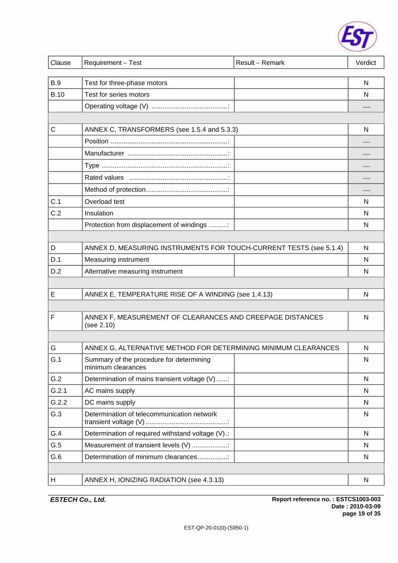
B.9 Test for three-phase motors N
B.10 Test for series motors N
Operating voltage (V) .........................................: ⎯
C ANNEX C, TRANSFORMERS (see 1.5.4 and 5.3.3) N
Position ...............................................................: ⎯
Manufacturer ......................................................: ⎯
Type ....................................................................: ⎯
Rated values .....................................................: ⎯
Method of protection............................................: ⎯
C.1 Overload test N
C.2 Insulation N
Protection from displacement of windings ..........: N
D ANNEX D, MEASURING INSTRUMENTS FOR TOUCH-CURRENT TESTS (see 5.1.4) N
D.1 Measuring instrument N
D.2 Alternative measuring instrument N
E ANNEX E, TEMPERATURE RISE OF A WINDING (see 1.4.13) N
F ANNEX F, MEASUREMENT OF CLEARANCES AND CREEPAGE DISTANCES (see 2.10)
N
G ANNEX G, ALTERNATIVE METHOD FOR DETERMINING MINIMUM CLEARANCES N
G.1 Summary of the procedure for determining minimum clearances
N
G.2 Determination of mains transient voltage (V)......: N
G.2.1 AC mains supply N
G.2.2 DC mains supply N
G.3 Determination of telecommunication network transient voltage (V) ............................................:
N
G.4 Determination of required withstand voltage (V).: N
G.5 Measurement of transient levels (V) ...................: N
G.6 Determination of minimum clearances................: N
H ANNEX H, IONIZING RADIATION (see 4.3.13) N

Clause Requirement − Test Result − Remark Verdict
Report reference no. : ESTCS1003-003Date : 2010-03-09
ESTECH Co., Ltd.
page 20 of 35
EST-QP-20-01(0)-(S950-1)
J ANNEX J, TABLE OF ELECTROCHEMICAL POTENTIALS (see 2.6.5.6) N
Metal used ........................................................... : ⎯
K ANNEX K, THERMAL CONTROLS (see 1.5.3 and 5.3.7) N
K.1 Making and breaking capacity N
K.2 Thermostat reliability; operating voltage (V)........: N
K.3 Thermostat endurance test; operating voltage (V) ......................................................................:
N
K.4 Temperature limiter endurance; operating voltage (V) .......................................................................:
N
K.5 Thermal cut-out reliability N
K.6 Stability of operation N
L ANNEX L, NORMAL LOAD CONDITIONS FOR SOME TYPES OF ELECTRICAL BUSINESS EQUIPMENT (see 1.2.2.1 and 4.5.1)
P
L.1 Typewriters N
L.2 Adding machines and cash registers N
L.3 Erasers N
L.4 Pencil sharpeners N
L.5 Duplicators and copy machines N
L.6 Motor-operated files N
L.7 Other business equipment P
M ANNEX M, CRITERIA FOR TELEPHONE RINGING SIGNALS (see 2.3.1) N
M.1 Introduction N
M.2 Method A N
M.3 Method B N
M.3.1 Ringing signal N
M.3.1.1 Frequency (Hz) ...................................................: ⎯
M.3.1.2 Voltage (V) ..........................................................: ⎯
M.3.1.3 Cadence; time (s), voltage (V) ...........................: ⎯
M.3.1.4 Single fault current (mA)......................................: ⎯
M.3.2 Tripping device and monitoring voltage ..............: N
M.3.2.1 Conditions for use of a tripping device or a monitoring voltage
N

Clause Requirement − Test Result − Remark Verdict
Report reference no. : ESTCS1003-003Date : 2010-03-09
ESTECH Co., Ltd.
page 21 of 35
EST-QP-20-01(0)-(S950-1)
M.3.2.2 Tripping device N
M.3.2.3 Monitoring voltage (V) .........................................: N
N ANNEX N, IMPULSE TEST GENERATORS (see 2.10.3.4, 6.2.2.1, 7.3.2 and clause G.5)
N
N.1 ITU-T impulse test generators N
N.2 IEC 60065 impulse test generator N
P ANNEX P, NORMATIVE REFERENCES N
Q ANNEX Q, BIBLIOGRAPHY N
R ANNEX R, EXAMPLES OF REQUIREMENTS FOR QUALITY CONTROL PROGRAMMES
N
R.1 Minimum separation distances for unpopulated coated printed boards (see 2.10.6)
N
R.2 Reduced clearances (see 2.10.3) N
S ANNEX S, PROCEDURE FOR IMPULSE TESTING (see 6.2.2.3) N
S.1 Test equipment N
S.2 Test procedure N
S.3 Examples of waveforms during impulse testing N
T ANNEX T, GUIDANCE ON PROTECTION AGAINST INGRESS OF WATER (see 1.1.2) N
⎯
U ANNEX U, INSULATED WINDING WIRES FOR USE WITHOUT INTERLEAVED INSULATION (see 2.10.5.4)
N
⎯
V ANNEX V, AC POWER DISTRIBUTION SYSTEMS (see 1.6.1) N
V.1 Introduction N
V.2 TN power distribution systems N
W ANNEX W, SUMMATION OF TOUCH CURRENTS N
W.1 Touch current from electronic circuits N
W.1.2 Earthed circuits N

Clause Requirement − Test Result − Remark Verdict
Report reference no. : ESTCS1003-003Date : 2010-03-09
ESTECH Co., Ltd.
page 22 of 35
EST-QP-20-01(0)-(S950-1)
W.2 Interconnection of several equipments N
W.2.1 Isolation N
W.2.2 Common return, isolated from earth N
W.2.3 Common return, connected to protective earth N
X ANNEX X, MAXIMUM HEATING EFFECT IN TRANSRORMER TESTS (see clause C.1)
N
X.1 Determination of maximum input current N
X.2 Overload test procedure N
Y ANNEX Y, ULTRAVIOLET LIGHT CONDITIONING TEST (see 4.3.13.3) N
Y.1 Test apparatus ...................................................: N
Y.2 Mounting of test samples ...................................: N
Y.3 Carbon-arc light-exposure apparatus ................: N
Y.4 Xenon-arc light exposure apparatus ..................: N
CENELEC COMMON MODIFICATIONS [C], SPECIAL NATIONAL CONDITIONS [S] AND A-DEVIATIONS (NATIONAL DEVIATIONS) [A] (EN 60950-1:2001, Annex ZB and Annex ZC)
N
General C: Delete all the "country" notes in the reference document according to the following list: 1.1.5 Note 2 1.5.8 Note 2 1.6.1 Note 1.7.2 Note 4 1.7.12 Note 2 2.6 Note 2.2.3 Note 2.2.4 Note 2.3.2 Note 2, 7, 82.3.3 Note 1, 2 2.3.4 Note 2,3 2.7.1 Note 2.10.3.1 Note 4 3.2.1.1 Note 3.2.3 Note 1, 2 3.2.5.1 Note 2 4.3.6 Note 1,2 4.7.2.2 Note 4.7.3.1 Note 2 6.1.2.1 Note 6.1.2.2 Note 6.2.2 Note 6.2.2.1 Note 2 6.2.2.2 Note 7 Note 4 7.1 Note G2.1 Note 1, 2 Annex H Note 2
N
1.2.4.1 S (DK): Certain types of Class I appliances (see 3.2.1.1) may be provided with a plug not establishing earthing conditions when inserted into Danish socket-outlets.
N
1.5.1 A (SE, Ordinance 1990:944 and CH, Ordinance on environmentally hazardous substances SR 814.013, Annex 3.2, Mercury): Add NOTE – Switches containing mercury such as thermostats, relays and level controllers are not allowed.
N
1.5.8 S (NO): Due to the IT power system used (see annex V, Fig. V.7), capacitors are required to be rated for the applicable line-to-line voltage (230 V).
N

Clause Requirement − Test Result − Remark Verdict
Report reference no. : ESTCS1003-003Date : 2010-03-09
ESTECH Co., Ltd.
page 23 of 35
EST-QP-20-01(0)-(S950-1)
1.7.2 S (FI, NO, SE): CLASS I PLUGGABLE EQUIPMENT TYPE A intended for connection to other equipment or a network shall, if safety relies on connection to protective earth or if surge suppressors are connected between the network terminals and accessible parts, have a marking stating that the equipment must be connected to an earthed mains socket-outlet. The marking text in the applicable countries shall be as follows:
N
FI: "Laite on liitettävä suojamaadoitus-koskettimilla varustettuun pistorasiaan"
N
NO: "Apparatet må tilkoples jordet stikkontakt" N
SE: "Apparaten skall anslutas till jordat uttag" N
A (DK, Heavy Current Regulations): Supply cords of class I equipment, which is delivered without a plug, must be provided with a visible tag with the following text: Vigtigt! Lederen med grøn/gul isolation må kun tilsluttes en klemme mærket
eller If essential for the safety of the equipment, the tag must in addition be provided with a diagram which shows the connection of the other conductors, or be provided with the following text: "For tilslutning af de øvrige ledere, se medfølgende instalationsvejledning."
N
1.7.5 S (DK): Socket-outlets for providing power to other equipment shall be in accordance with the Heavy Current Regulations, Section 107-2-D1, Standard Sheet DK 1-3a, DK 1-5a or DK 1-7a, when used on Class I equipment. For stationary equipment the socket-outlet shall be in accordance with Standard Sheet DK 1-1b or DK 1-5a.
N
1.7.5 A (DK, Heavy Current Regulations): CLASS II EQUIPMENT shall not be fitted with socket-outlets for providing power to other equipment.
N

Clause Requirement − Test Result − Remark Verdict
Report reference no. : ESTCS1003-003Date : 2010-03-09
ESTECH Co., Ltd.
page 24 of 35
EST-QP-20-01(0)-(S950-1)
1.7.12 A (DE, Gesetz über techische Arbeitsmittel (Gerätesicherheitsgesetz) [Law on technical labour equipment Equipment safety law], of 23rd October 1992, Article 3, 3rd paragraph, 2nd sentence, together with the "Allgemeine Verwaltungsvorschrift zur Durchführung des Zweiten Abschnitts des Gerätesicherheits-gesetzes" [General administrative regulation on the execution of the Second Section of the Equipment safety law], of 10th January 1996, article 2, 4th paragraph item 2): Directions for use with rules to prevent certain hazards for (among others) maintenance of the technical labour equipment, also for imported technical labour equipment shall be written in the German language. NOTE: Of this requirement, rules for use even only by service personnel are not exempted.
N
1.7.15 A (CH, Ordinance on environmentally hazardous substances SR 814.013): Annex 4.10 of SR 814.013 applies for batteries.
N
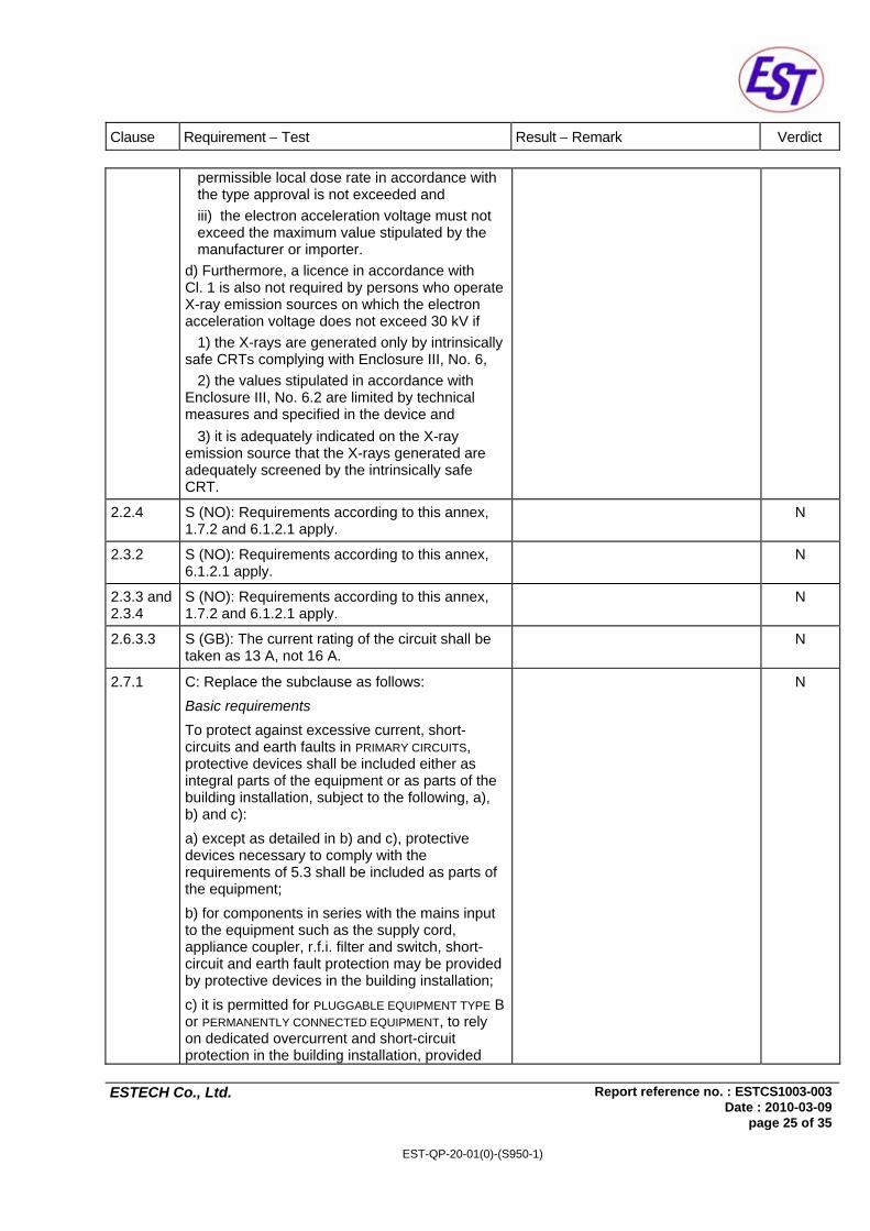
A (DE, Regulation on protection against hazards by X-ray, of 8th January 1987, Article 5 [Operation of X-ray emission source], clauses 1 to 4): a) A licence is required by those who operate an X-ray emission source. b) A licence in accordance with Cl. 1 is not required by those who operate an X-ray emission source on which the electron acceleration voltage does not exceed 20 kV if 1) the local dose rate at a distance of 0,1 m from the surface does not exceed 1 ìSv/h and 2) it is adequately indicated on the X-ray emission source that i) X-rays are generated and ii) the electron acceleration voltage must not exceed the maximum value stipulated by the manufacturer or importer. c) A licence in accordance with Cl. 1 is also not required by persons who operate an X-ray emission source on which the electron acceleration voltage exceeds 20 kV if 1) the X-ray emission source has been granted a type approval and 2) it is adequately indicated on the X-ray emission source that i) X-rays are generated ii) the device stipulated by the manufacturer or importer guarantees that the maximum
N
Clause Requirement − Test Result − Remark Verdict
Report reference no. : ESTCS1003-003Date : 2010-03-09
ESTECH Co., Ltd.
page 25 of 35
EST-QP-20-01(0)-(S950-1)
permissible local dose rate in accordance with the type approval is not exceeded and iii) the electron acceleration voltage must not exceed the maximum value stipulated by the manufacturer or importer. d) Furthermore, a licence in accordance with Cl. 1 is also not required by persons who operate X-ray emission sources on which the electron acceleration voltage does not exceed 30 kV if 1) the X-rays are generated only by intrinsically safe CRTs complying with Enclosure III, No. 6, 2) the values stipulated in accordance with Enclosure III, No. 6.2 are limited by technical measures and specified in the device and 3) it is adequately indicated on the X-ray emission source that the X-rays generated are adequately screened by the intrinsically safe CRT.
2.2.4 S (NO): Requirements according to this annex, 1.7.2 and 6.1.2.1 apply.
N
2.3.2 S (NO): Requirements according to this annex, 6.1.2.1 apply.
N
2.3.3 and 2.3.4
S (NO): Requirements according to this annex, 1.7.2 and 6.1.2.1 apply.
N
2.6.3.3 S (GB): The current rating of the circuit shall be taken as 13 A, not 16 A.
N
2.7.1 C: Replace the subclause as follows: Basic requirements
To protect against excessive current, short-circuits and earth faults in PRIMARY CIRCUITS, protective devices shall be included either as integral parts of the equipment or as parts of the building installation, subject to the following, a), b) and c): a) except as detailed in b) and c), protective devices necessary to comply with the requirements of 5.3 shall be included as parts of the equipment; b) for components in series with the mains input to the equipment such as the supply cord, appliance coupler, r.f.i. filter and switch, short-circuit and earth fault protection may be provided by protective devices in the building installation; c) it is permitted for PLUGGABLE EQUIPMENT TYPE B or PERMANENTLY CONNECTED EQUIPMENT, to rely on dedicated overcurrent and short-circuit protection in the building installation, provided
N
Clause Requirement − Test Result − Remark Verdict
Report reference no. : ESTCS1003-003Date : 2010-03-09
ESTECH Co., Ltd.
page 26 of 35
EST-QP-20-01(0)-(S950-1)
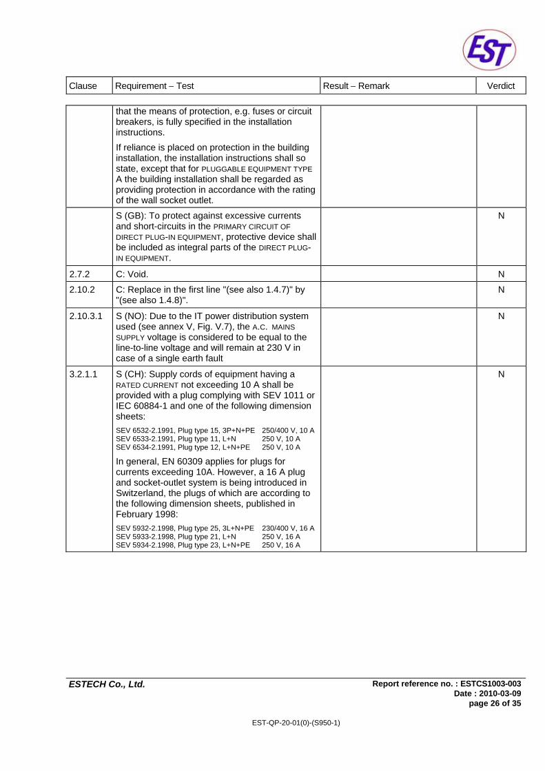
that the means of protection, e.g. fuses or circuit breakers, is fully specified in the installation instructions. If reliance is placed on protection in the building installation, the installation instructions shall so state, except that for PLUGGABLE EQUIPMENT TYPE A the building installation shall be regarded as providing protection in accordance with the rating of the wall socket outlet.
S (GB): To protect against excessive currents and short-circuits in the PRIMARY CIRCUIT OF DIRECT PLUG-IN EQUIPMENT, protective device shall be included as integral parts of the DIRECT PLUG-IN EQUIPMENT.
N
2.7.2 C: Void. N
2.10.2 C: Replace in the first line "(see also 1.4.7)" by "(see also 1.4.8)".
N
2.10.3.1 S (NO): Due to the IT power distribution system used (see annex V, Fig. V.7), the A.C. MAINS SUPPLY voltage is considered to be equal to the line-to-line voltage and will remain at 230 V in case of a single earth fault
N
3.2.1.1 S (CH): Supply cords of equipment having a RATED CURRENT not exceeding 10 A shall be provided with a plug complying with SEV 1011 or IEC 60884-1 and one of the following dimension sheets: SEV 6532-2.1991, Plug type 15, 3P+N+PE 250/400 V, 10 ASEV 6533-2.1991, Plug type 11, L+N 250 V, 10 A SEV 6534-2.1991, Plug type 12, L+N+PE 250 V, 10 A
In general, EN 60309 applies for plugs for currents exceeding 10A. However, a 16 A plug and socket-outlet system is being introduced in Switzerland, the plugs of which are according to the following dimension sheets, published in February 1998: SEV 5932-2.1998, Plug type 25, 3L+N+PE 230/400 V, 16 ASEV 5933-2.1998, Plug type 21, L+N 250 V, 16 A SEV 5934-2.1998, Plug type 23, L+N+PE 250 V, 16 A
N
Clause Requirement − Test Result − Remark Verdict
Report reference no. : ESTCS1003-003Date : 2010-03-09
ESTECH Co., Ltd.
page 27 of 35
EST-QP-20-01(0)-(S950-1)
S (DK): Supply cords of single-phase equipment having a rated current not exceeding 13 A shall be provided with a plug according to the Heavy Current Regulations, Section 107-2-D1. CLASS I EQUIPMENT provided with socket-outlets with earth contacts or which are intended to be used in locations where protection against indirect contact is required according to the wiring rules shall be provided with a plug in accordance with standard sheet DK 2-1a or DK 2-5a. If ply-phase equipment and single-phase equipment having a RATED CURRENT exceeding 13 A is provided with a supply cord with a plug, this plug shall be in accordance with the Heavy Current Regulations, Section 107-2-D1 or EN 60309-2.
N
S (ES): Supply cords of single-phase equipment having a rated current not exceeding 10 A shall be provided with a plug according to UNE 20315:1994. Supply cords of single-phase equipment having a rated current not exceeding 2,5 A shall be provided with a plug according to UNE-EN 50075:1993. CLASS I EQUIPMENT provided with socket-outlets with earth contacts or which are intended to be used in locations where protection against indirect contact is required according to the wiring rules, shall be provided with a plug in accordance with standard UNE 20315:1994. If poly-phase equipment is provided with a supply cord with a plug, this plug shall be in accordance with UNE-EN 60309-2.
N
S (GB): Apparatus which is fitted with a flexible cable or cord and is designed to be connected to a mains socket conforming to BS 1363 by means of that flexible cable or cord and plug, shall be fitted with a 'standard plug' in accordance with Statutory Instrument 1768:1994 – The Plugs and Socket etc. (Safety) Regulations 1994, unless exempted by those regulations. NOTE – 'Standard plug' is defined in SI 1768:1994 and essentially means an approved plug conforming to BS 1363 or an approved conversion plug.
N

Clause Requirement − Test Result − Remark Verdict
Report reference no. : ESTCS1003-003Date : 2010-03-09
ESTECH Co., Ltd.
page 28 of 35
EST-QP-20-01(0)-(S950-1)
S (IE): Apparatus which is fitted with a flexible cable or cord and is designed to be connected to a mains socket conforming to I.S. 411 by means of that flexible cable or cord and plug, shall be fitted with a 13 A plug in accordance with Statutory Instrument 525:1997 – National Standards Authority of Ireland (section 28) (13 A Plugs and Conversion Adaptors for Domestic Use) Regulations 1997.
N
3.2.3 C: Delete Note 1 and in Table 3A, delete the conduit sizes in parentheses.
N
3.2.5.1 C: Replace "60245 IEC 53" by "H05 RR-F"; "60227 IEC 52" by "H03 VV-F or H03 VVH2-F"; "60227 IEC 53" by "H05 VV-F or H05 VVH2-F2".In Table 3B, replace the first four lines by the following: Up to and including 6 0,751) Over 6 up to and including 10 (0,75)2) 1,0 Over 10 up to and including 16 (1,0)3) 1,5 In the Conditions applicable to Table 3B delete the words "in some countries" in condition 1). In Note 1, applicable to Table 3B, delete the second sentence.
N
3.2.5.1 S (GB): A power supply cord with conductor of 1,25 mm2 is allowed for equipment with a rated current over 10 A and up to and including 13 A.
N
3.3.4 C: In table 3D, delete the fourth line: conductor sizes for 10 to 13 A, and replace with the following:
N
"Over 10 up to and including 16 1,5 to 2,5 1,5 to 4" N
Delete the fifth line: conductor sizes for 13 to 16 A.
N
3.3.4 S (GB): The range of conductor sizes of flexible cords to be accepted by terminals for equipment with A RATED CURRENT of over 10 A up to and including 13 A is: - 1,25 mm2 to 1,5 mm2 nominal cross-sectional area.
N
4.3.6 S (GB): The torque test is performed using a socket outlet complying with BS 1363 and the plug part OF DIRECT PLUG-IN EQUIPMENT shall be assessed to BS 1363: Part 1, 12.1, 12.2, 12.3, 12.9, 12.11, 12.12, 12.16 and 12.17, except that the test of 12.17 is performed at not less than 125 °C.
N

Clause Requirement − Test Result − Remark Verdict
Report reference no. : ESTCS1003-003Date : 2010-03-09
ESTECH Co., Ltd.
page 29 of 35
EST-QP-20-01(0)-(S950-1)
S (IE): DIRECT PLUG-IN EQUIPMENT is known as plug similar devices. Such devices shall comply with Statutory Instrument 526:1997 – National Standards Authority of Ireland (Section 28) (Electrical plugs, plug similar devices and sockets for domestic use) Regulations, 1997.
N
4.3.13.6 C: Add the following note: NOTE Attention is drawn to 1999/519/EC: Council Recommendation on the limitation of exposure of the general public to electromagnetic fields 0 Hz to 300 GHz. Standards taking into account this recommendation are currently under development.
N
6.1.2.1 S (FI, NO, SE): Add the following text between the first and second paragraph: If this insulation is solid, including insulation forming part of a component, it shall at least consist of either - two layers of thin sheet material, each of which shall pass the electric strength test below, or - one layer having a distance through insulation of at least 0,4 mm, which shall pass the electric strength test below. If this insulation forms part of a semiconductor component (e.g. an optocoupler), there is no distance through insulation requirement for the insulation consisting of an insulating compound completely filling the casing, so that CLEARANCES AND CREEPAGE DISTANCES do not exist, if the component passes the electric strength test in accordance with the compliance clause below and in addition - passes the tests and inspection criteria of 2.10.8 with an electric strength test of 1,5 kV multiplied by 1,6 (the electric strength test of 2.10.7 shall be performed using 1,5 kV), and - is subject to ROUTINGE TESTING for electric strength during manufacturing, using a test voltage of 1,5 kV. It is permitted to bridge this insulation with a capacitor complying with EN 132400:1994, subclass Y2. A capacitor classified Y3 according to EN 132400:1994, may bridge this insulation under the following conditions: - the insulation requirements are satisfied by having a capacitor classified Y3 as defined by EN 132400, which in addition to the Y3 testing, is tested with an impulse test of 2,5 kV defined in
N

Clause Requirement − Test Result − Remark Verdict
Report reference no. : ESTCS1003-003Date : 2010-03-09
ESTECH Co., Ltd.
page 30 of 35
EST-QP-20-01(0)-(S950-1)
EN 60950:2000, 6.2.2.1; - the additional testing shall be performed on all the test specimens as described in EN 132400; - the impulse test of 2,5 kV is to be performed before the endurance test in EN 132400, in the sequence of tests as described in EN 132400.
6.1.2.2 S (FI, NO, SE): The exclusions are applicable for PERMANENTLY CONNECTED EQUIPMENT and PLUGGABLE EQUIPMENT TYPE B and equipment intended to be used in a RESTRICTED ACCESS LOCATION where equipotential bonding has been applied, e.g. in a telecommunication centre, and which has provision for a permanently connected PROTECTIVE EARTHING CONDUCTOR and is provided with instructions for the installation of that conductor by a service person.
N
7.1 S (FI, NO, SE): Requirements according to this annex, 6.1.2.1 and 6.1.2.2 apply with the term TELECOMMUNICATION NETWORK in 6.1.2 being replaced by the term CABLE DISTRIBUTION SYSTEM.
N
G.2.1 S (NO): Due to the IT power distribution system used (see annex V, Fig. V.7), the A.C. MAINS SUPPLY voltage is considered to be equal to the line-to-line voltage, and will remain at 230 V in case of a single earth fault.
N
Annex H C: Replace the last paragraph of this annex by: At any point 10 cm from the surface of the operator access area, the dose rate shall not exceed 1 µSv/h (0,1 mR/h) (see note). Account is taken of the background level. Replace the notes as follows: NOTE These values appear in Directive 96/29/Euratom. Delete Note 2.
N
Annex P C: Replace the text of this annex by: See annex ZA.
N
Annex Q C: Replace the title of IEC 61032 by "Protection of persons and equipment by enclosures – Probes for verification". Add the following notes for the standards indicated: IEC 60127 NOTE Harmonized as EN 60127 (Series) (not modified) IEC 60269-2-1 NOTE Harmonized as HD 630.2.1 S4:2000 (modified) IEC 60529 NOTE Harmonized as EN 60529:1991 (not modified) IEC 61032 NOTE Harmonized as EN 61032:1998 (not modified) IEC 61140 NOTE Harmonized as EN 61140:2001 (not modified) ITU-T Recommendation K.31 NOTE in Europe, the suggested document is EN 50083-1.
N

Clause Requirement − Test Result − Remark Verdict
Report reference no. : ESTCS1003-003Date : 2010-03-09
ESTECH Co., Ltd.
page 31 of 35
EST-QP-20-01(0)-(S950-1)
Annex ZA
C: NORMATIVE REFERENCES TO INTERNATIONAL PUBLICATIONS WITH THEIR RELEVANT EUROPEAN PUBLICATIONS This European Standard incorporates, by dated or undated reference, provisions from other publications. These normative references are cited at the appropriate places in the text and the publications are listed hereafter. For dated references, subsequent amendments to or revisions of any of these publications apply to this European Standard only when incorporated in it by amendment or revision. For undated references, the latest edition of the publication referrd to applies (including amendments). NOTE When an international publication has been modified by common modifications, indicated by (mod), the relevant EN/HD applies.
N
⎯ IEC 60050-151 ⎯ IEC 60050-195 EN 60065:1998 + corr. June 1999 IEC 60065 (mod):1998 EN 60073:1996 IEC 60073:1996 HD 566 S1:1990 IEC 60085:1984 HD 214 S2:1980 IEC 60112:1979 HD 611.4.1.S1:1992 IEC 60216-4-1:1990 HD 21 1) Series IEC 60227 (mod) Series HD 22 2) Series IEC 60245 (mod) Series EN 60309 Series IEC 60309 Series EN 60317-43:1997 IEC 60317-43:1997 EN 60320 Series IEC 60320 (mod) Series HD 384.3 S2:1995 IEC 60364-3 (mod):1993 HD 384.4.41 S2:1996 IEC 60364-4-41 (mod):1992 3) EN 132400:1994 4)
+ A2:1998 + A3:1998 + A4:2001 IEC 60384-14:1993
EN 60417-1 IEC 60417-1 HD 625.1 S1:1996 + corr. Nov. 1996 IEC 60664-1 (mod):1992 EN 60695-2-2:1994 IEC 60695-2-2:1991 EN 60695-2-11:2001 IEC 60695-2-11:2000 ⎯ IEC 60695-2-20:1995 ⎯ IEC 60695-10-2:1995 ⎯ IEC 60695-11-3:2000 ⎯ IEC 60695-11-4:2000 EN 60695-11-10:1999 IEC 60695-11-10:1999 EN 60695-11-20:1999 IEC 60695-11-20:1999 EN 60730-1:2000 IEC 60730-1:1999 (mod) EN 60825-1:1994 + corr. Febr. 1995 +
A11:1996 + corr. July 1997 IEC 60825-1:1993
EN 60825-2:2000 IEC 60825-2:2000 ⎯ IEC 60825-9:1999 EN 60851-3:1996 IEC 60851-3:1996 EN 60851-5:1996 IEC 60825-5:1996 EN 60851-6:1996 IEC 60851-6:1996 ⎯ IEC 60885-1:1987 EN 60990:1999 IEC 60990:1999 ⎯ IEC 61058-1:2000 EN 61965:2001 IEC 61965:2000 EN ISO 178:1996 ISO 178:1993 EN ISO 179 Series ISO 179 Series

Clause Requirement − Test Result − Remark Verdict
Report reference no. : ESTCS1003-003Date : 2010-03-09
ESTECH Co., Ltd.
page 32 of 35
EST-QP-20-01(0)-(S950-1)
EN ISO 180:2000 ISO 180:1993 ⎯ ISO 261:1998 ⎯ ISO 262:1998 EN ISO 527 Series ISO 527 Series ⎯ ISO 386:1984 EN ISO 4892 Series ISO 4892 Series ⎯ ISO 7000:1989 EN ISO 8256:1996 ISO 8256:1990 ⎯ ISO 9772:1994 EN ISO 9773:1998 ISO 9773:1998 ⎯ ITU-T:1988 Recommendation K.17 ⎯ ITU-T:2000 Recommendation K.21 1) The HD 21 series is related to, but not directly equivalent with the IEC 60227 series
2) The HD 22 series is related to, but not directly equivalent with the IEC 60245 series 3) IEC 60364-4-41:1992 is superseded by IEC 60364-4-41:2001 4) EN 132400, Sectional Specification: Fixed capacitors for electromagnetic interference suppression and connection to the supply mains (Assessment level D), and its amendments are related to, but not directly equivalent to IEC 60384-14

Report reference no. : ESTCS1003-003Date : 2010-03-09
ESTECH Co., Ltd.
page 33 of 35
EST-QP-20-01(0)-(S950-1)
1.5.1 TABLE: list of critical components P object/part No. manufacturer/
trademark type/model technical data standard mark(s) of
conformity1)
Enclosure LG CHEMICAL GP-5001A-F V-0, 60 deg C, min 1,5 mm thick Overall approx. 130 by 45 by 27 mm.
UL746 UL (E67171)
LED LENS MITSUBISHI RAYON
MF HB, 50 deg C, min 1,5 mm thick.
UL746 UL (E54695)
Lithium battery (BT1)
SEIKO MS920S or MS920SE
Max charging current: 300 mA
UL1642 UL (MH15628)
Lithium battery protection device(D4)
Various Various 50 V, SMD IEC 60950-1 Tested in Appliance
Lithium battery protection device(R6, R7)
Various Various 470 ohm, 1/10 W, SMD
IEC 60950-1 Tested in Appliance
PWB Various Various Min. V-1, Min. 130 deg.C
UL 796 UL
1) an asterisk indicates a mark which assures the agreed level of surveillance 1.6.2 TABLE: electrical data (in normal conditions) P
fuse # Irated (A) U (V) P (W) I (mA) Ifuse (mA) condition/status - 1,5 12,18 dc 1,6 153 - Max. normal load
2.10.3 and 2.10.4
TABLE: clearance and creepage distance measurements N
clearance cl and creepage distance dcr at/of:
Up (V)
U r.m.s. (V)
required cl (mm)
cl (mm)
required dcr (mm)
dcr (mm)
2.10.5 TABLE: distance through insulation measurements N distance through insulation di at/of: Up
(V) test voltage
(V) required di
(mm) di
(mm)

Report reference no. : ESTCS1003-003Date : 2010-03-09
ESTECH Co., Ltd.
page 34 of 35
EST-QP-20-01(0)-(S950-1)
4.5 TABLE: maximum temperatures P
test voltage (V) ................................ : 12 V dc ⎯
tamb1 (°C) .......................................... : 23,9 ⎯
tamb2 (°C) .......................................... : 23,9 Tma: 50 °C
⎯
maximum temperature T of part/at:: T (°C) allowed Tmax (°C)
U18 body 41,6 67,7 130(PWB)
RLY1 body 37,6 63,7 130(PWB)
EC1 body 43,0 69,1 130(PWB)
L3 body 48,2 74,3 130(PWB)
39,7 65,8 130(PWB)
38,8 64,9 130(PWB)
U17 body 55,4 81,5 130(PWB)
U12 body 39,6 65,7 130(PWB)
BT1(Lithium battery) body 41,0 67,1 130(PWB)
PWB near U2 41,8 67,9 130(PWB)
Outer surface of enclosure, front 32,7 58,8 95(Plastic)
Rear metal bracket body 32,2 58,3 70(Metal)
temperature T of winding: R1 (Ω) R2 (Ω) T (°C) allowed
Tmax (°C) insulation class
4.5.2 TABLE: ball pressure test of thermoplastic parts N
allowed impression diameter (mm) .....................: ≤ 2 mm ⎯ part test temperature (°C) impression diameter
(mm)
4.7 TABLE: resistance to fire N
part manufacturer of material type of material thickness (mm)
flammability class

Report reference no. : ESTCS1003-003Date : 2010-03-09
ESTECH Co., Ltd.
page 35 of 35
EST-QP-20-01(0)-(S950-1)
5.2 TABLE: electric strength tests, impulse tests and voltage surge tests N test voltage applied between: test voltage (V)
a.c. / d.c. breakdown Yes / No
supplementary information 5.3 TABLE: fault condition tests P
ambient temperature (°C) ................................... : 24 - 26 ⎯
model/type of power supply ................................ : ⎯ ⎯
manufacturer of power supply ............................ : ⎯ ⎯
rated markings of power supply .......................... : - ⎯ component No.
fault test voltage (V)
test time fuse No.
fuse current(A)
result
Lithium battery protection (D4)
short - 30min - - Max charging current : 300 mA; Measured : 3,5 mA; No hazard
Lithium battery protection (R6)
short - 30min - - Max charging current : 300 mA; Measured : 6,5 mA; No hazard
Lithium battery protection (R7)
short - 30min - - Max charging current : 300 mA; Measured : 6,5 mA; No hazard
supplementary information


![PSR-S950/S750 Reference Manual - Home - Yamaha ... PSR-S950/S750 Reference Manual Panel Button Chart ( [CHANNEL ON/OFF] CHANNEL ON/OFF display SONG — 2 STYLE 1/2 or 2/2 (PSR-S950)](https://static.fdocuments.us/doc/165x107/5ad09e167f8b9ad24f8de05a/psr-s950s750-reference-manual-home-yamaha-psr-s950s750-reference-manual.jpg)
