TEST REPORT AS/NZS 4777.2 Grid connection of energy ...
92
Test Report issued under the responsibility of: Page 1 of 92 TEST REPORT AS/NZS 4777.2 Grid connection of energy systems via inverters Part 2: Inverter requirements Report: Report Reference No… ...................: 6052106.50C Tested by (name + signature) ..........: Albert Liang Approved by (name + signature) ......: Jason Guo Date of issue ...................................: 2019-09-11 Total number of pages ...................: 92 pages Testing Laboratory ........................: DEKRA Testing and Certification (Suzhou) Co., Ltd Address ...........................................: No. 99, Hongye Road, Suzhou Industrial Park Suzhou, 215006, P.R. China Applicant’s name...........................: EAST Group Co., Ltd. Address ...........................................: No.6 Northern Industry Road, Songshan Lake Sci. & Tech. Industrial Park, Dongguan City, Guangdong Province, China Test specification: Standard .........................................: AS/NZS 4777.2:2015 Test procedure ................................: Type test Non-standard test method ...............: N/A Test Report Form No. ....................: AS/NZS 4777.2_V2.0 TRF Originator.................................: DEKRA Testing and Certification (Shanghai) Co., Ltd. Master TRF .....................................: 2015-11 Test item description.....................: Grid-connected PV inverter Trade Mark ......................................: Manufacturer ...................................: EAST Group Co., Ltd. No.6 Northern Industry Road, Songshan Lake Sci. & Tech. Industrial Park, Dongguan City, Guangdong Province, China Model/Type reference ......................: EA5KTSI, EA6KTSI, EA8KTSI, EA10KTSI, EA13KTSI, EA16KTSI
Transcript of TEST REPORT AS/NZS 4777.2 Grid connection of energy ...

Test Report issued under the responsibility of:
Page 1 of 92
TEST REPORT AS/NZS 4777.2
Grid connection of energy systems via inverters Part 2: Inverter requirements
Report:
Report Reference No… ...................: 6052106.50C
Tested by (name + signature) ..........: Albert Liang
Approved by (name + signature) ......: Jason Guo
Date of issue ...................................: 2019-09-11
Total number of pages ...................: 92 pages
Testing Laboratory ........................: DEKRA Testing and Certification (Suzhou) Co., Ltd
Address ...........................................: No. 99, Hongye Road, Suzhou Industrial Park Suzhou, 215006, P.R. China
Applicant’s name ...........................: EAST Group Co., Ltd.
Address ...........................................: No.6 Northern Industry Road, Songshan Lake Sci. & Tech. Industrial Park, Dongguan City, Guangdong Province, China
Test specification:
Standard .........................................: AS/NZS 4777.2:2015
Test procedure ................................: Type test
Non-standard test method ...............: N/A
Test Report Form No. ....................: AS/NZS 4777.2_V2.0
TRF Originator .................................: DEKRA Testing and Certification (Shanghai) Co., Ltd.
Master TRF .....................................: 2015-11
Test item description .....................: Grid-connected PV inverter
Trade Mark ......................................:
Manufacturer ...................................: EAST Group Co., Ltd.
No.6 Northern Industry Road, Songshan Lake Sci. & Tech. Industrial Park, Dongguan City, Guangdong Province, China
Model/Type reference ......................: EA5KTSI, EA6KTSI, EA8KTSI, EA10KTSI, EA13KTSI, EA16KTSI

Page 2 of 92 Report No. 6052106.50C
Rating ............................................. : EA5KTSI: PV input: Max. 1000 Vdc, MPPT voltage range: 120-950 Vdc, max 11A /11 A, Isc PV: 12 A/12 A Output: 230/400 Vac, 3/N/PE, 50 Hz, 5000 VA, max 7.3 A
EA6KTSI: PV input: Max. 1000 Vdc, MPPT voltage range: 120-950 Vdc, max 11 A/11 A, Isc PV: 12 A/12 A Output: 230/400 Vac, 3/N/PE, 50 Hz, 6000 VA, max 8.7 A
EA8KTSI: PV input: Max. 1000 Vdc, MPPT voltage range: 120-950 Vdc, max 11 A/11 A, Isc PV: 12 A/12 A Output: 230/400 Vac, 3/N/PE, 50 Hz, 8000 VA, max 11.6 A
EA10KTSI: PV input: Max. 1000 Vdc, MPPT voltage range: 200-950 Vdc, max 11 A, Isc PV: 12 A/12 A Output: 230/400 Vac, 3/N/PE, 50 Hz, 10000 VA, max 14.5 A
EA13KTSI: PV input: Max. 1000 Vdc, MPPT voltage range: 200-950 Vdc, max 22 A/11 A, Isc PV: 24 A/12 A Output: 230/400 Vac, 3/N/PE, 50 Hz, 13000 VA, max 18.9 A
EA16KTSI: PV input: Max. 1000 Vdc, MPPT voltage range: 200-950 Vdc, max 22 A/11 A, Isc PV: 24 A/12 A Output: 230/400 Vac, 3/N/PE, 50 Hz, 16000 VA, max 23.2 A
Class of equipment ......................... : Class I Class II Class III Not classified
Mass of equipment (kg)................... : 25
Pollution degree .............................. : Outside PD3; Inside PD2
IP protection class ........................... : IP65
Possible test case verdicts:
- test case does not apply to the test object .............................................. : N/A
- test object does meet the requirement ..................................... : P(Pass)
- test object does not meet the requirement ..................................... : F(Fail)
Testing ........................................... :
Date of receipt of test item ............... : 2019-04-10 (samples provided by applicant)
Date (s) of performance of tests ....... : 2019-04-10 to 2019-09-11

Page 3 of 92 Report No. 6052106.50C
General remarks:
"(see appended table)" refers to a table appended to the report.
"(see Appendix #)" refers to additional information appended to the report.
The test results presented in this report relate only to the object tested.
The test results presented in this report relate only to the object tested.
This report shall not be reproduced, except in full, without the written approval of the Issuing testing
laboratory.
The measurement result is considered in conformance with the requirement if it is within the prescribed limit, It
is not necessary to account the uncertainty associated with the measurement result.
The information provided by the customer in this report may affect the validity of the results, the test lab is not
responsible for it.
This report is only for reference and is not used for legal proof function in China market.
Name and address of factory (ies):
EAST Group Co., Ltd.
No.6 Northern Industry Road, Songshan Lake Sci. & Tech. Industrial Park, Dongguan City, Guangdong
Province, China

Page 4 of 92 Report No. 6052106.50C
General product information:
The products are grid-connected photovoltaic inverter converts DC voltage into AC voltage, the unit is providing EMC filtering at the input and output towards mains.
The output was switched off redundant by the high power switching bridge and relay in series. This designation assures that the disconnection of the output circuit from the grid will also operate in case of one error.
The internal control is redundant built. It consists of two Microcontrollers (master DSP U1, slave DSP U22). The master DSP can control the relays; detect the PV voltage, PV current and BUS voltage, measures grid voltage, frequency, AC current with injected DC, insulation resistance to ground and residual current. The slave CPU (U22) were also detected grid voltage, injected DC current and residual current. Both microcontrollers communicate with each other. Any abnormal of those electrical parameter will trigger the disconnection of the inverter from the grid.
Block Diagram
Model difference:
1) The model EA5KTSI is identical with EA6KTSI; EA8KTSI is identical with EA10KTSI; EA13KTSI is identical with EA16KTSI in hardware and just power derating according to setting variations parameter in software.
2) The models EA5KTSI, EA6KTSI, EA8KTSI, EA10KTSI and EA13KTSI are identical with EA16KTSI in topological schematic circuit diagram of hardware except for the bus capacitors number (EA5KTSI and EA6KTSI with 2 bus capacitors, EA8KTSI and EA10KTSI with 4 bus capacitors, EA13KTSI and EA16KTSI with 6 bus capacitors); boost current sensor rating; inductive reactance of INV inductors and Boost inductors; Boost diode rating; Internal fan (Only model EA13KTSI and EA16KTSI designed with internal fan); the type designation and the input/output electrical rating.
The product was tested on:
Hardware version: 00C
Software version: HornetV008
Unless otherwise specified, all the tests were performed on model EA16KTSI and also applicable for all other models stated in this report. According to the user manual and testing, the product was evaluated for maximum ambient temperature of 60°C and will derating the output power above 45°C.

Page 5 of 92 Report No. 6052106.50C
Copy of marking plate:
Rating label:
Remark:
According to customer's requirement, these models were evaluated under the grid frequency of 50 Hz.
DRM label:

Page 6 of 92 Report No. 6052106.50C
AS 4777.2
Clause Requirement - Test Result - Remark Verdict
5 GENERAL REQUIREMENTS P
5.1 Electrical safety P
Inverters for use in inverter energy systems with photovoltaic (PV) arrays shall comply with the appropriate electrical safety requirements of IEC 62109-1 and IEC 62109-2, and the requirements within this Standard.
The unit of Grid-Connected PV Inverter was connected to PV arrays and mains.
P
Inverters for use in inverter energy systems that have energy storage (batteries) as the only possible energy source shall comply with the electrical safety requirements of AS 62040.1.1, and the requirements within this Standard.
N/A
Inverters for use in inverter energy systems that incorporate energy sources other than photovoltaic (PV) arrays or batteries shall comply with the applicable electrical safety requirements of IEC 62109-1 and IEC 62109-2, and the requirements within this Standard.
N/A
5.2 Provision for external connections P
Inverters shall be used and installed as fixed equipment only. Inverters shall not be used as portable equipment.
Inverter provisions for external connection
(a) shall be for fixed equipment only; and
(b) shall provide for safe and reliable connection to any d.c. source or load or any a.c. source or load.
P
All inverter ports (except communications ports) shall incorporate connection types for either-
i. permanently connected equipment; or
ii. pluggable type B equipment.
Pluggable type B equipment. P
5.3 Photovoltaic (PV) array earth fault/earth leakage detection P
For inverter energy systems used with PV array systems that require earth fault detection and a residual current detection, either internal or external to the inverter, the type of detection used shall be declared in accordance with IEC 62109-1 and IEC 62109-2.
See separated test report no . 6052106.50A for IEC 62109-1 and 6052106.50B for IEC 62109-2
P
If an external residual current device (RCD) is required, the manufacturer's installation instructions shall state the need for an RCD and shall specify its rating, type and required circuit location in accordance with Clause 9.
RCMU is integrated to the PV inverter.
N/A
Compliance shall be checked by inspection of the inverter's markings and manufacturer's documentation, and testing in accordance with IEC 62109-2.
P
Page 7 of 92 Report No. 6052106.50C
AS 4777.2
Clause Requirement - Test Result - Remark Verdict
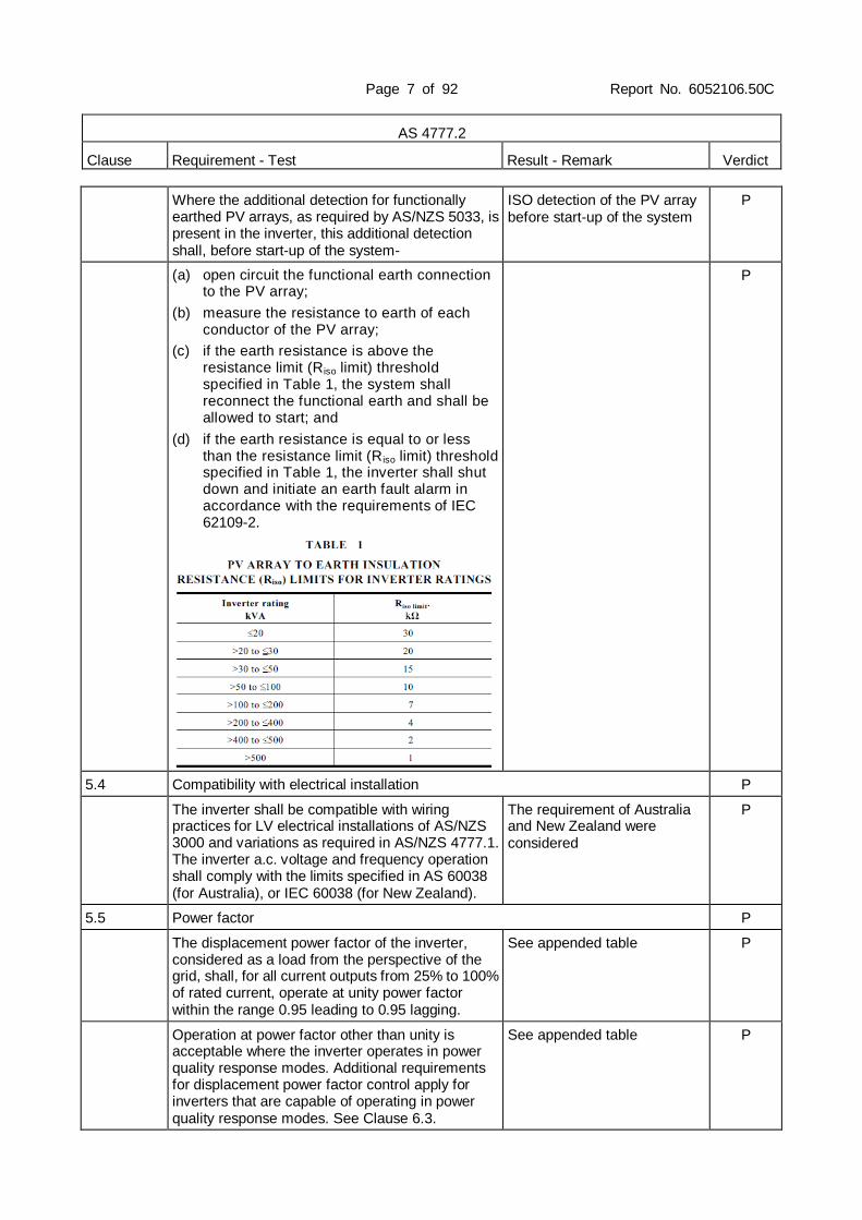
Where the additional detection for functionally earthed PV arrays, as required by AS/NZS 5033, is present in the inverter, this additional detection shall, before start-up of the system-
ISO detection of the PV array before start-up of the system
P
(a) open circuit the functional earth connection to the PV array;
(b) measure the resistance to earth of each conductor of the PV array;
(c) if the earth resistance is above the resistance limit (Riso limit) threshold specified in Table 1, the system shall reconnect the functional earth and shall be allowed to start; and
(d) if the earth resistance is equal to or less than the resistance limit (R iso limit) threshold specified in Table 1, the inverter shall shut down and initiate an earth fault alarm in accordance with the requirements of IEC 62109-2.
P
5.4 Compatibility with electrical installation P
The inverter shall be compatible with wiring practices for LV electrical installations of AS/NZS 3000 and variations as required in AS/NZS 4777.1. The inverter a.c. voltage and frequency operation shall comply with the limits specified in AS 60038 (for Australia), or IEC 60038 (for New Zealand).
The requirement of Australia and New Zealand were considered
P
5.5 Power factor P
The displacement power factor of the inverter, considered as a load from the perspective of the grid, shall, for all current outputs from 25% to 100% of rated current, operate at unity power factor within the range 0.95 leading to 0.95 lagging.
See appended table P
Operation at power factor other than unity is acceptable where the inverter operates in power quality response modes. Additional requirements for displacement power factor control apply for inverters that are capable of operating in power quality response modes. See Clause 6.3.
See appended table P

Page 8 of 92 Report No. 6052106.50C
AS 4777.2
Clause Requirement - Test Result - Remark Verdict
Compliance shall be determined by type testing in accordance with the power factor test specified in Appendix B.
See appended table P
5.6 Harmonic currents P
The harmonic currents of the inverter shall not exceed the limits specified in Tables 2 and 3 and the total harmonic current distortion (ITHD) to the 50th harmonic shall be less than 5%.
See appended table P
Compliance shall be determined by type testing in accordance with the harmonic current limit test specified in Appendix C.
See appended table P
5.7 Voltage fluctuations and flicker P
The inverter shall conform to the voltage fluctuation and flicker limits specified in AS/NZS 61000.3.3 for equipment with rated current less than or equal to 16 A per phase (a.c.).
See appended table P
For equipment with rated current greater than 16 A per phase (a.c.), the impedance shall be determined in accordance with the methods given in AS/NZS 61000.3.11. The values of Pst and Plt when tested using Zref and the network impedance value (Zref or Zmax) required for compliance shall be included in the inverter documentation.
See appended table P
5.8 Transient voltage limits P
To prevent damage to electrical equipment connected to the same circuit as the inverter, disconnection of the inverter from the grid shall not result in transient overvoltages beyond the limits specified in Table 4.
P
Page 9 of 92 Report No. 6052106.50C
AS 4777.2
Clause Requirement - Test Result - Remark Verdict
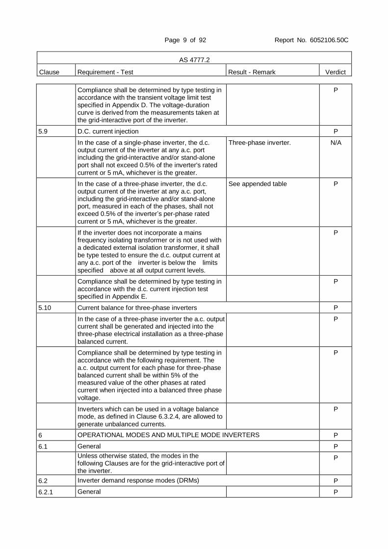
Compliance shall be determined by type testing in accordance with the transient voltage limit test specified in Appendix D. The voltage-duration curve is derived from the measurements taken at the grid-interactive port of the inverter.
P
5.9 D.C. current injection P
In the case of a single-phase inverter, the d.c. output current of the inverter at any a.c. port including the grid-interactive and/or stand-alone port shall not exceed 0.5% of the inverter's rated current or 5 mA, whichever is the greater.
Three-phase inverter. N/A
In the case of a three-phase inverter, the d.c. output current of the inverter at any a.c. port, including the grid-interactive and/or stand-alone port, measured in each of the phases, shall not exceed 0.5% of the inverter’s per-phase rated current or 5 mA, whichever is the greater.
See appended table P
If the inverter does not incorporate a mains frequency isolating transformer or is not used with a dedicated external isolation transformer, it shall be type tested to ensure the d.c. output current at any a.c. port of the inverter is below the limits specified above at all output current levels.
P
Compliance shall be determined by type testing in accordance with the d.c. current injection test specified in Appendix E.
P
5.10 Current balance for three-phase inverters P
In the case of a three-phase inverter the a.c. output current shall be generated and injected into the three-phase electrical installation as a three-phase balanced current.
P
Compliance shall be determined by type testing in accordance with the following requirement. The a.c. output current for each phase for three-phase balanced current shall be within 5% of the measured value of the other phases at rated current when injected into a balanced three phase voltage.
P
Inverters which can be used in a voltage balance mode, as defined in Clause 6.3.2.4, are allowed to generate unbalanced currents.
P
6 OPERATIONAL MODES AND MULTIPLE MODE INVERTERS P
6.1 General P
Unless otherwise stated, the modes in the following Clauses are for the grid-interactive port of the inverter.
P
6.2 Inverter demand response modes (DRMs) P
6.2.1 General P

Page 10 of 92 Report No. 6052106.50C
AS 4777.2
Clause Requirement - Test Result - Remark Verdict
The inverter shall support the demand response mode DRM 0 of Table 5. The inverter should support the other demand response modes of Table 5.
P
The inverter shall detect and initiate a response to all supported demand response commands within 2 s. The inverter shall continue to respond while the mode remains asserted.
P
6.2.2 Interaction with demand response enabling device (DRED)
P
The inverter shall have a means of connecting to a DRED. This means of connection shall include a terminal block or RJ45 socket. The terminal block or RJ45 socket shall comply with the minimum electrical specifications in Table 6. The terminal block or RJ45 socket may be physically mounted in the inverter or in a separate device that remotely communicates with the inverter.
P
6.3 Inverter power quality response modes P
6.3.1 General P
The inverter may have the capability of operating in modes which will-
P
(a) contribute to maintaining the power quality at the point of connection with the customer installation; or
P
(b) provide characteristics which are outside the typical operation of an inverter for the purpose of providing support to a grid.
P
These various operating modes may be enabled or disabled in an inverter and may include the following:
P
i. Volt response modes. See appended table P
ii. Fixed power factor or reactive power mode. See appended table P
iii. Power response mode. See appended table P

Page 11 of 92 Report No. 6052106.50C
AS 4777.2
Clause Requirement - Test Result - Remark Verdict
iv. Power rate limit. See appended table P
If these power quality response modes are available in the inverter, the inverter shall comply with the relevant requirements of this Clause (6) and Clause 5, and all of the requirements of Clauses 7 and 8, when these modes are enabled or disabled.
P
Compliance shall be determined by type testing as specified in Appendix I with the applicable modes disabled and enabled.
P
If these power quality response modes of operation are controlled by an external device, the external device shall not interfere with the inverter complying with the relevant requirements of this Clause (6) and Clause 5, and all of the requirements of Clauses 7 and 8, when the external device is controlling these modes.
No external device uesd. N/A
6.3.2 Volt response modes P
6.3.2.1 General P
6.3.2.2 Volt-watt response mode P
The volt-watt response mode varies the output power of the inverter in response to the voltage at its terminal. The inverter should have the volt-watt response mode. If this mode is available, it shall be enabled by default.
P
6.3.2.3 Volt-var response mode P
The volt-var response mode varies the reactive power output of the inverter in response to the voltage at its grid-interactive port. The inverter should have the volt-var response capability. If this mode is available, it shall be disabled by default.
See appended table P
6.3.2.4 Voltage balance modes P
A voltage imbalance between phases may occur in an electrical installation that presents a load that is not balanced across the phases. Three-phase inverters, or single-phase inverters used in a three-phase combination may be used for voltage balancing between phases by injecting unbalanced three-phase currents into the electrical installation.
P
If the voltage balance mode is available, the following requirements apply:
P
(a) The voltage balance mode shall be disabled by default.
P
(b) For single-phase inverters used in a three-phase combination, the requirements of Clause 8.2 apply.
N/A

Page 12 of 92 Report No. 6052106.50C
AS 4777.2
Clause Requirement - Test Result - Remark Verdict
(c) The voltage balancing mode shall be able to-
i. operate correctly with a single fault applied;
ii. detect the fault or loss of operability and cause the inverter to revert to injecting current into the three-phase electrical installation as a three-phase balanced current; or
iii. detect the fault or loss of operability and disconnect the inverter from the electrical installation.
P
6.3.3 Fixed power factor mode and reactive power mode P
The fixed power factor mode and the reactive power mode may be required in some situations by the electrical distributor to meet local grid requirements.
See appended table. P
If the inverter is capable of operating with reactive power mode, the maximum ratio of reactive power (vars) to rated apparent power should be 100%. The reactive power modes may be required to be fixed at a constant reactive power by the electrical distributor.
P
If the inverter is capable of operating with fixed power factor mode, the minimum range of settings should be 0.8 leading to 0.8 lagging. The fixed power factor mode is for control of the displacement power factor over the range of inverter power output.
P
6.3.4 Characteristic power factor curve for cos φ (P) (Power response)
See appended table P
The characteristic power factor curve for cos φ (P) (Power response) mode varies the displacement power factor of the output of the inverter in response to changes in the output power of the inverter, i.e. cos φ (P) modes.
P
The response curve required for the cos φ (P) response should be defined within displacement power factor range of 0.9 leading to 0.9 lagging. One possible cos φ (P) curve is shown in Figure 4.
P
6.3.5 Power rate limit P
6.3.5.1 General P
The power rate limit for an inverter is a power quality response mode. The inverter shall have the capability to rate limit changes in power generation through the grid-interactive port.
P
Inverters capable of multiple mode operation should have the capability to rate limit changes in power consumption (for example increasing/decreasing of charging rates of connected energy storage).
P

Page 13 of 92 Report No. 6052106.50C
AS 4777.2
Clause Requirement - Test Result - Remark Verdict
The power rate limit only applies to the changes specified in Clause 6.3.5.3.
P
The power rate limit does not apply when the inverter disconnection device is required to operate (i.e. to disconnect).
P
6.3.5.2 Gradient of power rate limit P
The power rate limit (WGra) is the ramp rate of real power output in response to changes in power and is defined as a percentage of rated power per minute. The nominal ramp time (Tn) is the nominal time for a 100% change in output power with a power rate limit of WGra. An inverter shall have an adjustable power rate limit (WGra) which limits the change in power output to the set power rate limit. The default setting for the power rate limit (WGra) for increase and decrease shall be 16.67% of rated power per minute which is a nominal ramp time of 6 min.
where,
Tn = nominal ramp time in minutes (default value is 6 min)
100%= total change from no output to rated power output or from rated power output to no output.
P
The power rate limit (WGra) shall be adjustable within the range 5% to 100% of rated power per minute. It is acceptable to have two separate power rate limits for increase and decrease in output power, as follows:
P
(a) To rate limit an increase in power (WGra +). P
(b) To rate limit a decrease in power (WGra -). P
6.3.5.3 Power rate limit modes P
6.3.5.3.1 General P
The inverter power rate limit (WGra) is applicable to operate in the following modes:
(a) Soft ramp up after connect or reconnect.
(b) Changes in a.c. operation and control.
(c) Changes in energy source operation.
The following subclauses provide operation information for each mode.
P
6.3.5.3.2 Soft ramp up after connect or reconnect P
All inverters shall have this mode. This mode shall be enabled as per Clause 7.7 and for the increase in power required by Clause 7.5.3 after frequency decreased to the required limit.
P
6.3.5.3.3 Changes in a.c. operation and control P

Page 14 of 92 Report No. 6052106.50C
AS 4777.2
Clause Requirement - Test Result - Remark Verdict
If available, this mode shall be enabled for a change in a demand response mode of Clause 6.2 (except for DRM 0). When a demand response mode of Clause 6.2 (except for DRM 0) is asserted or unasserted the power rate limit (WGra) shall apply to the increase or decrease in power generation or consumption and the transitions between power output levels.
P
6.3.5.3.4 Changes in energy source operation N/A
This mode only applies to multiple mode inverters with energy storage.
N/A
6.3.5.4 Nonlinearity of power rate limit changes P
The nonlinearity (NL) of the power rate limit (WGra) in response to an increase of the inverter power output, as defined by the characteristic curve depicted in Figure 5, shall be less than 10%.
P
The following equation shall be used to calculate the maximum nonlinearity:
P
6.4 Multiple mode inverter operation N/A
6.4.1 General N/A
When the multiple mode inverter is disconnected from the grid any stand-alone port shall ensure that all active conductors are also isolated from the grid-interactive port.
N/A
Multiple mode inverters shall be arranged to ensure that the continuity of the neutral conductor to the load from the electrical installation is not interrupted when the inverter disconnects from the grid and supplies a load via the stand-alone port.
N/A
Multiple mode inverters shall be arranged such that only the allowed installation methods of AS/NZS 3000 and AS/NZS 4777.1 can be used.
N/A
When the multiple mode inverter is providing the stand-alone function and is disconnected from the grid, the stand-alone port shall comply with the requirements for d.c. current injection (refer to Clause 5.9) into the connected load circuits. The type of RCD compatible with and for use on the stand-alone function outputs shall be declared.
N/A
6.4.2 Sinusoidal output in stand-alone mode N/A

Page 15 of 92 Report No. 6052106.50C
AS 4777.2
Clause Requirement - Test Result - Remark Verdict
The a.c. output voltage waveform of a stand-alone port of a multiple mode inverter operating in stand-alone mode, shall comply with the requirements of this Clause (6.4.2). The a.c. output voltage waveform of a stand-alone mode shall have a voltage total harmonic distortion (THD) not exceeding of 5% and no individual harmonic at a level exceeding 5%.
N/A
6.4.3 Volt-watt response mode for charging of energy storage
N/A
The volt-watt response mode for charging of energy storage varies the power input of the inverter from the grid in response to the voltage at its grid-interactive port. A multiple mode inverter with energy storage which can be charged from the grid shall have this volt-watt response mode. This volt-watt response mode is only active when power from the grid is required to charge the energy storage.
N/A
The response curve required for the volt-watt response is defined by the volt response reference values in Table 9 and corresponding power consumption from the grid through the grid-interactive port for charging energy storage. The default values are listed in Table 12 and shown in Figure 6.
N/A
6.5 Security of operational settings P
The internal settings of the demand response or power quality response modes of the inverter shall be secured against inadvertent or unauthorized tampering. Changes to the internal settings shall require the use of a tool and special instructions not provided to unauthorized personnel.
P
The installer-accessible settings shall be capable of being adjusted within the values specified in this Clause (6).
P
7 PROTECTIVE FUNCTIONS FOR CONNECTION TO ELECTRICAL INSTALLATIONS AND THE GRID
P
7.1 General P
There shall be an automatic disconnection device to prevent injection of energy into the point of supply and prevent the formation of an unintentional island with the grid or part thereof when supply is disrupted from the grid.
P
The automatic disconnection device shall operate- P

Page 16 of 92 Report No. 6052106.50C
AS 4777.2
Clause Requirement - Test Result - Remark Verdict
(a) if supply from the grid is disrupted;
(b) when the grid goes outside preset parameters (e.g. under-voltage/over-voltage, under-frequency/over-frequency); or
(c) when the demand response mode DRM 0 (see Clause 6.2) is asserted.
P
For inverter energy systems connected to multiple phases the automatic disconnection device shall operate if any of the above conditions is met on any phase.
P
The automatic disconnection device may be within the inverter or a separate device.
The automatic disconnection device within the inverter.
P
7.2 Automatic disconnection device P
The automatic disconnection device shall prevent power (both a.c. and d.c.) from entering the grid when the automatic disconnection device operates.
P
The automatic disconnection device shall provide isolation in all live conductors.
P
Automatic disconnection devices for isolation shall comply with the following requirements:
P
(a) They shall be capable of withstanding an impulse voltage likely to occur at the point of installation, or have an appropriate contact gap.
P
(b) They shall not be able to falsely indicate that the contacts are open.
P
(c) They shall be designed and installed so as to prevent unintentional closure, such as might be caused by impact, vibration or the like.
P
(d) They shall be devices that disconnect all live conductors (active and neutral) of the inverter from the grid-interactive port.
P
(e) They shall be such that with a single fault applied to the automatic disconnection device or to any other location in the inverter, at least basic insulation or simple separation is maintained between the energy source port and the grid-interactive port when the means of disconnection is intended to be in the open state.
P
(f) They shall be such that with a single fault applied to the automatic disconnection device or to any other location in the inverter, power is prevented from entering the grid.
P
The automatic disconnection device shall be capable of interrupting at least the rated current.
P

Page 17 of 92 Report No. 6052106.50C
AS 4777.2
Clause Requirement - Test Result - Remark Verdict
The settings of the automatic disconnection device shall not exceed the capability of the inverter.
P
A semiconductor (solid-state) device shall not be used for isolation purposes.
P
7.3 Active anti-islanding protection P
The automatic disconnection device shall incorporate at least one method of active anti-islanding protection such as below:
See appended table.
P
(a) shifting the frequency of the inverter away from nominal conditions in the absence of a reference frequency (frequency shift);
P
(b) allowing the frequency of the inverter to be inherently unstable in the absence of a reference frequency (frequency instability);
N/A
(c) periodically varying the output power of the inverter (power variation); and
N/A
(d) monitoring for sudden changes in the impedance of the grid by periodically injecting a current pulse (current injection).
N/A
The method used to provide active anti-islanding protection shall be declared.
P
To prevent islanding, the active anti-islanding protection system shall operate the automatic disconnection device (see Clause 7.2) within 2 s of disruption to the power supply from the grid.
P
Compliance shall be determined by type testing in accordance with the active anti-islanding tests specified in Appendix F or IEC 62116.
Type testing in accordance with the standard of IEC 62116.
P
7.4 Voltage and frequency limits (passive anti-islanding protection) P
The automatic disconnection device shall incorporate the following forms of passive anti-islanding protection:
P
(a) Undervoltage and overvoltage protection. P
(b) Under-frequency and over-frequency protection.
P
For sustained variation of the voltage and frequency beyond each limit specified in Table 13, the automatic disconnection device (see Clause 7.2) shall operate no sooner than the required trip delay time and before the maximum disconnection time.
P

Page 18 of 92 Report No. 6052106.50C
AS 4777.2
Clause Requirement - Test Result - Remark Verdict
This requires the inverter to remain in continuous, uninterrupted operation for voltage variations with a duration shorter than the trip delay time specified in Table 13.
P
Each protective function limit shall be preset and secured against change.
P
Compliance shall be determined by type testing in accordance with the voltage and frequency limits tests specified in Appendix G.
P
7.5 Limits for sustained operation P
7.5.1 General P
The inverter or inverter energy system shall remain connected over the range of voltages and frequencies that it is required to be compatible with. Refer to Clause 5.4.
P
7.5.2 Sustained operation for voltage variations P
The inverter shall operate the automatic disconnection device (see Clause 7.2) within 3 s when the average voltage for a 10 min period exceeds the Vnom-max, where Vnom-max lies in the range 244-258 V.
P
The sustained operation for voltage variations shall not interfere with the active and passive anti-islanding requirements of Clauses 7.3 and 7.4.
P
The limit Vnom-max shall be preset to the default set-point and may be programmable up to the maximum 258 V. The default set-point for Vnom-max shall be as follows:
P
(a) In Australia: 255 V. P
(b) In New Zealand: 248 V. P
The 10 min average value shall be compared against the limit Vnom-max at least every 3 s to determine when to disconnect.
P
Compliance shall be determined by type testing in accordance with the sustained operation for voltage variations test specified in Appendix H.
P
7.5.3 Sustained operation for frequency variations P
7.5.3.1 Response to an increase infrequency P

Page 19 of 92 Report No. 6052106.50C
AS 4777.2
Clause Requirement - Test Result - Remark Verdict
The inverter shall be capable of supplying rated power between 47 Hz and 50.25 Hz for Australia.
P
The inverter shall be capable of supplying rated power between 45 Hz and 50.25 Hz for New Zealand.
P
When a grid frequency disturbance results in an increase in grid frequency which exceeds 50.25 Hz, the inverter shall reduce the power output linearly with an increase of frequency until fstop is reached, where fstop lies in the range 51-52 Hz.
P
The power level present at the time the frequency reaches or exceeds 50.25 Hz shall be held as the reference power level used to calculate the required response to the increasing frequency.
This is expressed in the equation below:
P
When the frequency exceeds fstop the inverter power output shall be ceased (i.e. 0 W). The default set-point for fstop shall be 52 Hz.
P
The output power shall remain at or below the lowest power level reached in response to an over-frequency event between 50.25 Hz and fstop This is to provide hysteresis in the control of the inverter. When the grid frequency has decreased back to 50.15 Hz or less for at least 60 s, the power level shall be increased at a rate no greater than the power rate limit (WGra) of Clause 6.3.5 until the available energy source power is reached. Figure 7(A) shows this.
P
Unconstrained power operation may recommence 6 min after the frequency returns to and remains at less than 50.15 Hz.
P
Compliance shall be determined by type testing in accordance with the sustained operation for frequency variations test specified in Appendix H.
P
7.5.3.2 Response to a decrease in grid frequency N/A
This requirement applies only to inverters with energy storage.
The tested inverters was not used with energy storage.
N/A
The inverter shall be capable of charging the energy storage between 49.75 Hz and 52.0 Hz.
N/A
When a grid frequency disturbance results in a decrease in grid frequency which falls below 49.75 Hz, an inverter with energy storage which is charging from the grid port should reduce the power input for charging linearly with a decrease of frequency until fstop-CH is reached, where fstop-cH lies in the range 47-49Hz.
N/A
Page 20 of 92 Report No. 6052106.50C
AS 4777.2
Clause Requirement - Test Result - Remark Verdict
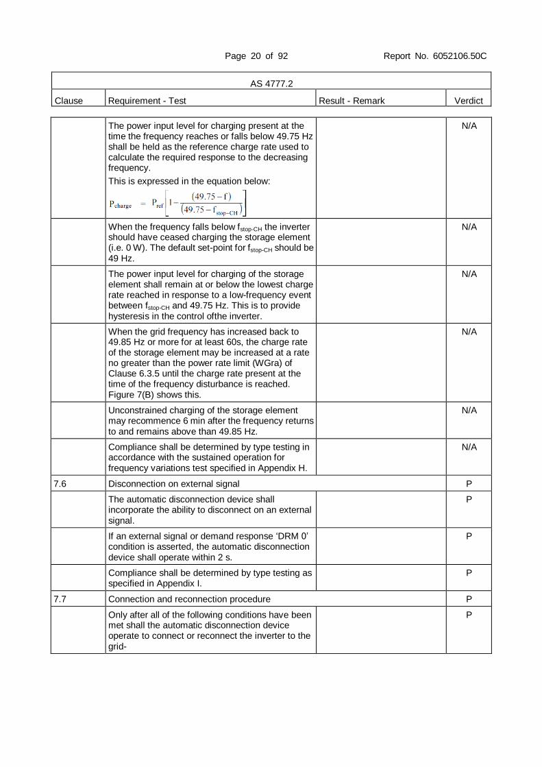
The power input level for charging present at the time the frequency reaches or falls below 49.75 Hz shall be held as the reference charge rate used to calculate the required response to the decreasing frequency.
This is expressed in the equation below:
N/A
When the frequency falls below fstop-CH the inverter should have ceased charging the storage element (i.e. 0 W). The default set-point for fstop-CH should be 49 Hz.
N/A
The power input level for charging of the storage element shall remain at or below the lowest charge rate reached in response to a low-frequency event between fstop-CH and 49.75 Hz. This is to provide hysteresis in the control ofthe inverter.
N/A
When the grid frequency has increased back to 49.85 Hz or more for at least 60s, the charge rate of the storage element may be increased at a rate no greater than the power rate limit (WGra) of Clause 6.3.5 until the charge rate present at the time of the frequency disturbance is reached. Figure 7(B) shows this.
N/A
Unconstrained charging of the storage element may recommence 6 min after the frequency returns to and remains above than 49.85 Hz.
N/A
Compliance shall be determined by type testing in accordance with the sustained operation for frequency variations test specified in Appendix H.
N/A
7.6 Disconnection on external signal P
The automatic disconnection device shall incorporate the ability to disconnect on an external signal.
P
If an external signal or demand response ‘DRM 0’ condition is asserted, the automatic disconnection device shall operate within 2 s.
P
Compliance shall be determined by type testing as specified in Appendix I.
P
7.7 Connection and reconnection procedure P
Only after all of the following conditions have been met shall the automatic disconnection device operate to connect or reconnect the inverter to the grid-
P

Page 21 of 92 Report No. 6052106.50C
AS 4777.2
Clause Requirement - Test Result - Remark Verdict
(a) the voltage of the grid has been maintained within the limits of AS 60038 (for Australia) or IEC 60038 (for New Zealand) for at least 60 s;
(b) the frequency of the grid has been maintained within the range 47.5 Hz to 50.15 Hz for at least 60 s;
(c) the inverter and the grid are synchronized and in-phase with each other; and
(d) no external signal is present or DRM 0 asserted requiring the system to be disconnected.
P
Compliance shall be determined by type testing in accordance with the tests as specified in Appendix F and Appendix G.
P
7.8 Security of protection settings P
The internal settings of the automatic disconnection device shall be secured against inadvertent or unauthorized tampering. Changes to the internal settings shall require the use of a tool and special instructions not provided to unauthorized personnel.
NOTE: Special interface devices and passwords are regarded as tools.
Changes to the internal settings shall require the use of a tool and special instructions not provided to unauthorized personnel.
P
The installer-accessible settings of the automatic disconnection device shall be capable of being adjusted within the limits specified in Clause 7.5.
P
The manufacturer settings of the automatic disconnection device, specified in Clause 7.4, shall be secured against changes.
P
8 MULTIPLE INVERTER COMBINATIONS N/A
8.1 General N/A
There are installations where multiple inverter energy systems are used and the electrical installation connects at a single point of supply to the grid. Inverter energy systems are often comprised of multiple inverters used in combination to provide the desired inverter energy system capacity or to ensure that voltage balance is maintained in multiple phase connections to the grid.
N/A
This Clause (8) specifies the requirements and tests for inverter energy systems used in such combinations. If a combination is not tested, it should not be used or external devices should be used in accordance with the requirements of AS/NZS 4777.1.
N/A

Page 22 of 92 Report No. 6052106.50C
AS 4777.2
Clause Requirement - Test Result - Remark Verdict
Possible combinations are single-phase inverters used in parallel, single-phase inverters used in multiple phase installations and three-phase inverters used in parallel.
N/A
8.2 Inverter current balance across multiple phases N/A
In a three-phase inverter system comprised of individual single-phase inverters the a.c. output current should be generated and injected into the three-phase electrical installation as a three-phase balanced current. The maximum current imbalance in a three-phase inverter system comprised of individual single-phase inverters shall be no more than 21.7 A.
N/A
8.3 Grid disconnection N/A
When any inverter within the inverter energy system disconnects as required by Clause 7, all inverters within the inverter energy system shall disconnect within 2 s of the first inverter disconnecting. This applies to all inverters used in combination for single-phase or multiple phases.
N/A
8.4 Grid connection and reconnection N/A
When multiple inverters are used together in a multiple phase combination, only after all the conditions of Clause 7.7 have been met on all connected phases shall the automatic disconnection device operate to connect or reconnect any inverter of the multiple phase combination to the grid.
N/A
Where any inverter used in a multiple phase combination has a rated current exceeding 21.7 A per phase, the requirement of Clause 8.2 shall be met when connecting or reconnecting.
N/A
8.5 Testing combinations N/A
8.5.1 Single-phase combinations N/A
Single-phase parallel combinations of inverters shall be tested for combinations with total rated current (Irated) equal to or up to the maximum of 6 A per phase.
N/A
8.5.2 Single-phase inverters used in three-phase combinations
N/A
For single-phase inverters with rated current (Irated) greater than or equal to 5 A used in three-phase combinations, three inverters shall be tested in a three-phase arrangement [refer to Figure 8(a)].
N/A
Single-phase inverters with rated current less than 5 A and to be used in three-phase combinations shall be tested in combination with at least two inverters per phase [refer to Figure 8(b)].
N/A
8.5.3 Required tests for multiple inverter combinations N/A
Page 23 of 92 Report No. 6052106.50C
AS 4777.2
Clause Requirement - Test Result - Remark Verdict
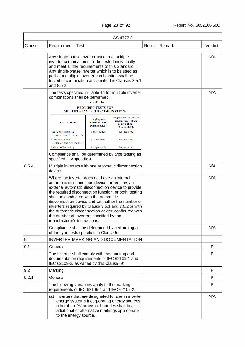
Any single-phase inverter used in a multiple inverter combination shall be tested individually and meet all the requirements of this Standard. Any single-phase inverter which is to be used as part of a multiple inverter combination shall be tested in combination as specified in Clauses 8.5.1 and 8.5.2.
N/A
The tests specified in Table 14 for multiple inverter combinations shall be performed.
Compliance shall be determined by type testing as specified in Appendix J.
N/A
8.5.4 Multiple inverters with one automatic disconnection device
N/A
Where the inverter does not have an internal automatic disconnection device, or requires an external automatic disconnection device to provide the required disconnection function, or both, testing shall be conducted with the automatic disconnection device and with either the number of inverters required by Clause 8.5.1 and 8.5.2 or with the automatic disconnection device configured with the number of inverters specified by the manufacturer's instructions.
N/A
Compliance shall be determined by performing all of the type tests specified in Clause 5.
N/A
9 INVERTER MARKING AND DOCUMENTATION
9.1 General P
The inverter shall comply with the marking and documentation requirements of IEC 62109-1 and IEC 62109-2, as varied by this Clause (9).
P
9.2 Marking P
9.2.1 General P
The following variations apply to the marking requirements of IEC 62109-1 and IEC 62109-2:
P
(a) Inverters that are designated for use in inverter energy systems incorporating energy sources other than PV arrays or batteries shall bear additional or alternative markings appropriate to the energy source.
N/A

Page 24 of 92 Report No. 6052106.50C
AS 4777.2
Clause Requirement - Test Result - Remark Verdict
(b) Inverters that are designated for use in closed electrical operating areas shall be marked with a warning stating that they are not suitable for installation in households or areas of a similar type or use (i.e. domestic).
N/A
9.2.2 Equipment ratings P
The inverter shall be marked with its ratings and the ratings of each port, as specified in Table 15. Only those ratings that are applicable to the type of inverter are required. The ratings shall be plainly and permanently marked on the inverter, in a location that is clearly visible after installation.
P
9.2.3 Ports P
Each port shall be marked with its classification and indicate whether a.c or d.c. voltage as appropriate.
P
Typical classifications include the following: See below. P
(a) PV (photovoltaic). P
(b) Wind turbine. N/A
(c) Energy storage. N/A
(d) Battery. N/A
(e) Generator. N/A
(f) Grid-interactive. P
(g) Stand-alone. N/A
(h) Communications (type). P
(i) DRM. P
(j) Load. N/A
9.2.4 External and ancillary equipment N/A
If the inverter requires external or ancillary equipment for compliance with this Standard, the requirement for any such equipment shall be marked on the inverter along with the following or an equivalent statement: ‘Refer to the installation instructions for type and ratings’ or symbol.
N/A
9.2.5 Residual current devices (RCDs) P
Inverter energy systems used with PV array systems require residual current detection in accordance with IEC 62109-1 and IEC 62109-2. The requirements can be met by the installation of a suitably rated RCD external to the inverter or by an RCMU integral to the inverter.
RCMU is integrated to the PV inverter.
P

Page 25 of 92 Report No. 6052106.50C
AS 4777.2
Clause Requirement - Test Result - Remark Verdict
Where an external RCD is required, the inverter shall be marked with a warning along with the rating and type of RCD required. The warning shall be located in a prominent position and written in lettering at least 5 mm high. It shall contain the following or an equivalent statement:
WARNING: AN RCD IS REQUIRED ON THE (NAME) PORTS OF THE INVERTER
N/A
If the inverter energy system requires a Type B RCD, the inverter shall be marked with a warning. The warning shall be located in a prominent position and written in lettering at least 5 mm high. It shall contain the following:
WARNING: A TYPE B RCD IS REQUIRED ON THE [NAME] PORTS OF THE INVERTER
N/A
9.2.6 Demand response modes P
The demand response modes supported by the inverter should be permanently marked on the name plate or on a durable sticker located on or near the demand response interface port to indicate the demand response modes of which the unit is capable.
P
Figure 9 illustrates an acceptable form of marking. If this form of marking is used, each box shall contain a tick or a cross (if the inverter has that capability) or remain blank (if it does not have that capability). Alternatively, only the modes supported may be marked.
P
If the physical interface is a terminal block, then-
(a) the terminals shall be engraved or otherwise durably marked; or
(b) a permanent label with ‘DRM Port’ shall be affixed near the terminal block.
The marking shall indicate which terminal corresponds to which demand response mode. The range of markings is indicated against Pins 1 to 6 in Table 7.
P
9.3 Documentation P
9.3.1 General P

Page 26 of 92 Report No. 6052106.50C
AS 4777.2
Clause Requirement - Test Result - Remark Verdict
The documentation supplied with the inverter shall provide all information necessary for the correct installation, operation and use of the system and any required external devices including information specified in Clause 9.2.
P
All inverters, including those intended for use in systems incorporating energy sources other than PV arrays or batteries, shall comply with the documentation requirements of IEC 62109-1 and IEC 62109-2.
P
9.3.2 Equipment ratings P
The documentation supplied with the inverter shall state the ratings of the inverter and the ratings for each port, as specified in Table 16. Only those ratings that are applicable to the type of inverter are required.
P
9.3.3 Ports P
In addition to the requirements of Clause 9.3.2, the documentation supplied with the inverter shall state the following for each port, as a minimum:
P
(a) Means of connection. P
(b) For pluggable equipment type B, the type of matching connectors to be used.
P
(c) External controls and protection requirements P
(d) Explanation of terminals or pins used for connection including polarity and voltage.
P
(e) Tightening torque to be applied to terminals. P
(f) Instructions for protective earthing. P
(g) Instructions for connection of loads and installation of RCD protection to stand-alone ports.
N/A
(h) The decisive voltage class (DVC). P
9.3.4 External and ancillary equipment No external device uesd. N/A
Where an inverter or multiple inverter combinations requires external or ancillary equipment for compliance with this Standard, the documentation shall-
N/A
(a) state the requirement for any such equipment;
(b) provide sufficient information to identify the external or ancillary equipment, either by manufacturer and part number or by type and rating; and
(c) specify assembly, location, mounting and connection requirements.
N/A
9.3.5 RCDs N/A

Page 27 of 92 Report No. 6052106.50C
AS 4777.2
Clause Requirement - Test Result - Remark Verdict
Where an external RCD is required, the following or an equivalent statement shall be included in the documentation: ‘External RCD Required’. The documentation shall also state the rating and type of RCD required and provide instructions for the installation of the RCD.
RCMU is integrated to the PV inverter.
N/A
9.3.6 Multiple mode inverters N/A
Where the inverter is capable of multiple mode operation, the documentation shall include the following:
N/A
(a) Ratings and means of connection to each source of supply to the inverter or output from the inverter.
(b) Any requirements related to wiring and external controls, including the method of maintaining neutral continuity within the electrical installation to any stand-alone ports as required.
(c) Disconnection means and isolation means.
(d) Overcurrent protection needed.
N/A
9.3.7 Multiple inverter combinations N/A
Where an inverter has been tested for use in a multiple inverter combination as per Clause 8, the documentation shall include the following:
N/A
(a) Valid combinations of inverters.
(b) Installation instructions for correct operation as a multiple inverter combination.
N/A

Page 28 of 92 Report No. 6052106.50C
AS 4777.2
Clause Requirement - Test Result - Remark Verdict
Appendix A GENERAL TEST AND REPORTING REQUIREMENTS (Normative)
P
Appendix B POWER FACTOR TEST (Normative) P
Appendix C HARMONIC CURRENT LIMIT TEST (Normative) P
Appendix D TRANSIENT VOLTAGE LIMIT TEST (Normative) P
Appendix E D.C. INJECTION TEST (Normative) P
Appendix F ACTIVE ANTI-ISLANDING TEST (Normative) P
Appendix G VOLTAGE AND FREQUENCY LIMITS (PASSIVE ANTI-ISLANDING PROTECTION) TESTS (Normative)
P
Appendix H LIMITS FOR SUSTAINED OPERATION (Normative)
P
Appendix I DEMAND AND POWER QUALITY RESPONSE MODE TESTING INCLUDING DISCONNECTION ON EXTERNAL SIGNAL (Normative)
P
Appendix J MULTIPLE INVERTER TESTING (Normative) N/A
Appendix K RELATED DOCUMENTS (Informative) P

Page 29 of 73 Report No: 6052106C
TRF No. AS/NZS 4777.2_V2.0
AS 4777.2:2015 Test Overview:
Clause Test Result
5.5 (Appendix B) Power factor P
5.6 (Appendix C) Harmonic currents & Voltage harmonic limits of test grid P
5.7 Voltage fluctuations and flicker P
5.8 (Appendix D) Transient voltage limits P
5.9 (Appendix E) D.C. current injection P
5.10 Current balance for three-phase inverters P
6.3.2.2 Volt-watt response mode P
6.3.2.3 Volt-var response mode P
6.3.2.4 Voltage balance modes P
6.3.4 Characteristic power factor curve for cos φ (P) (Power response) P
6.4.2 Sinusoidal output in stand-alone mode N/A
6.4.3 Volt-watt response mode for charging of energy storage N/A
7.3 (Appendix F) Active anti-islanding protection P
7.4 (Appendix G) Undervoltage and overvoltage trip test (passive anti-islanding protection)
P
7.4 (Appendix G) Under-frequency and over-frequency trip test (passive anti-islanding protection)
P
7.5.2 (Appendix H2) Sustained operation for voltage variations P
7.5.3.1 (Appendix H3) Response to an increase infrequency P
7.5.3.2 (Appendix H3) Response to a decrease in grid frequency P
7.6 (Appendix I) Disconnection on external signal P
7.7 (Appendix G) Connection and reconnection procedure P
7.8 Security of protection settings P
8 (Appendix J) Multiple inverter combinations N/A

Page 30 of 92 Report No. 6052106.50C
TRF No. AS/NZS 4777.2_V2.0
5.5 & 6.3.3 (Appendix B)
TABLE: Power factor Fixed power factor mode and reactive power mode
P
Model EA5KTSI
Item Measurement 15% 25% 50% 75% 100%
Unity power factor
Power (watts) 781.6 1295.7 2577.8 3860.7 5126.4
Reactive power (var) 186.0 152.4 143.5 3863.3 152.1
PF cos (phi) 0.972 0.993 0.998 0.999 1.000
Lead/lag Lead Lead Lead Lag Lead
Fixed power factor mode -Lag limit(PF=0.8)
Power (watt) 620.8 1040.5 2070.8 3099.6 4117.9
Reactive power (var) 465.2 775.9 1545.3 2318.1 3081.0
PF cos (phi) 0.800 0.801 0.801 0.801 0.801
Fixed power factor mode -Lead limit(PF=0.8)
Power (watt) 615.3 1028.6 2055.2 3083.7 4101.0
Reactive power (var) 463.6 776.3 1553.9 2344.0 3122.8
PF cos (phi) 0.798 0.798 0.798 0.796 0.796
Reactive power mode(- Lag)
Power (watt) 657.5 1054.7 2042.5 3025.4 4005.8
Reactive power (var) 3024.8 3021.5 3021.8 3037.9 3045.5
PF cos (phi) 0.212 0.330 0.560 0.706 0.796
Reactive power mode(- Lead)
Power (watt) 632.2 1029.7 2019.1 3003.9 3987.0
Reactive power (var) 2987.6 2992.6 2989.3 2983.2 2982.6
PF cos (phi) 0.207 0.325 0.560 0.710 0.801
Test procedure:
(a) The inverter shall be connected into a test circuit equivalent to that shown in Figure B 1. The voltage shall equal the grid test voltage.
(b) The simulated source supply shall be varied until the a.c. output of the inverter equals 15 ±5% of its rated current output.
(c) The displacement power factor of the inverter output shall be measured.
(d) Steps (b) and (c) shall be repeated with the inverter operating at 25 ±5%, 50 ±5%, 75 ±5% and 100 ±5% of its rated current output.
Criteria for acceptance:
For unity power factor: The displacement power factor of the inverter, considered as a load from the perspective of the grid, shall, for all current outputs from 25% to 100% of rated current, operate at unity power factor within the range 0.95 leading to 0.95 lagging.
For fixed power factor mode: the minimum range of settings should be 0.8 leading to 0.8 lagging.
For reactive power mode, the maximum ratio of reactive power (vars) to rated apparent power should be 100%. The reactive power modes may be required to be fixed at a constant reactive power by the electrical distributor.
The required accuracy for the measurement and reporting of results is ±0.01 PF. For testing at limits or in other modes, results shall be ±0.01 of the required limit, i.e. for a limit of 0.95, values equal to 0.94 to 0.96 are acceptable. The vars at the 15% test point are required to be the same or less than the vars at the 25% test point when operating at unity power factor.

Page 31 of 92 Report No. 6052106.50C
TRF No. AS/NZS 4777.2_V2.0
5.5 & 6.3.3 (Appendix B)
TABLE: Power factor Fixed power factor mode and reactive power mode
P
Model EA16KTSI
Item Measurement 15% 25% 50% 75% 100%
Unity power factor
Power (watts) 2491.6 4118.5 8229.8 12183.5 16206.3
Reactive power (var)
317.6 300.5 319.6 71.3 611.6
PF cos (phi) 0.992 0.997 0.999 1.000 0.999
Lead/lag Lead Lead Lead Lag Lead
Fixed power factor mode -Lag limit(PF=0.8)
Power (watt) 2008.9 3311.3 6562.4 9822.2 12599.8
Reactive power (var)
1512.0 2484.6 4927.2 7364.5 9481.8
PF cos (phi) 0.799 0.800 0.800 0.800 0.799
Fixed power factor mode -Lead limit(PF=0.8)
Power (watt) 2007.2 3300.6 6546.6 9752.6 12621.2
Reactive power (var)
1487.5 2449.1 4878.1 7327.5 9484.8
PF cos (phi) 0.803 0.803 0.802 0.799 0.799
Reactive power mode(- Lag)
Power (watt) 1949.7 3220.1 6471.3 9592.3 12884.3
Reactive power (var)
9615.4 9614.4 9605.9 9618.3 9633.9
PF cos (phi) 0.199 0.318 0.559 0.706 0.801
Reactive power mode(- Lag)
Power (watt) 1914.9 3186.0 6342.3 9563.0 12850.7
Reactive power (var)
9625.7 9632.2 9621.1 9599.9 9591.4
PF cos (phi) 0.195 0.314 0.550 0.706 0.801
Test procedure:
(e) The inverter shall be connected into a test circuit equivalent to that shown in Figure B 1. The voltage shall equal the grid test voltage.
(f) The simulated source supply shall be varied until the a.c. output of the inverter equals 15 ±5% of its rated current output.
(g) The displacement power factor of the inverter output shall be measured.
(h) Steps (b) and (c) shall be repeated with the inverter operating at 25 ±5%, 50 ±5%, 75 ±5% and 100 ±5% of its rated current output.
Criteria for acceptance:
For unity power factor: The displacement power factor of the inverter, considered as a load from the perspective of the grid, shall, for all current outputs from 25% to 100% of rated current, operate at unity power factor within the range 0.95 leading to 0.95 lagging.
For fixed power factor mode: the minimum range of settings should be 0.8 leading to 0.8 lagging.
For reactive power mode, the maximum ratio of reactive power (vars) to rated apparent power should be 100%. The reactive power modes may be required to be fixed at a constant reactive power by the electrical distributor.
The required accuracy for the measurement and reporting of results is ±0.01 PF. For testing at limits or in other modes, results shall be ±0.01 of the required limit, i.e. for a limit of 0.95, values equal to 0.94 to 0.96 are acceptable. The vars at the 15% test point are required to be the same or less than the vars at the 25% test point when operating at unity power factor.

Page 32 of 92 Report No. 6052106.50C
TRF No. AS/NZS 4777.2_V2.0
5.6 (Appendix C)
TABLE: Harmonic currents (Phase A) P
Model EA5KTSI
Component Limit 50% of rated current 100% of rated current
% of
fundamental Value
A % of
fundamental Value
A % of
fundamental
1st -- 3.547 100.000 7.092 100.000
2nd 1% 0.009 0.255 0.018 0.259
3rd 4% 0.011 0.300 0.021 0.300
4th 1% 0.003 0.077 0.005 0.072
5th 4% 0.029 0.820 0.058 0.824
6th 1% 0.006 0.171 0.011 0.158
7th 4% 0.007 0.202 0.014 0.204
8th 1% 0.002 0.069 0.005 0.071
9th 2% 0.006 0.164 0.012 0.162
10th 0.5% 0.002 0.063 0.005 0.066
11th 2% 0.010 0.287 0.020 0.287
12th 0.5% 0.001 0.037 0.003 0.038
13th 2% 0.012 0.350 0.025 0.347
14th 0.5% 0.001 0.038 0.003 0.038
15th 1% 0.004 0.112 0.008 0.114
16th 0.5% 0.002 0.048 0.003 0.046
17th 1% 0.004 0.113 0.008 0.112
18th 0.5% 0.002 0.043 0.003 0.042
19th 1% 0.004 0.123 0.008 0.117
20th 0.5% 0.001 0.026 0.002 0.025
21th 0.6% 0.004 0.121 0.009 0.122
22th 0.5% 0.001 0.014 0.001 0.015
23th 0.6% 0.006 0.162 0.012 0.163
24th 0.5% 0.001 0.034 0.002 0.033
25th 0.6% 0.006 0.167 0.012 0.166
26th 0.5% 0.001 0.020 0.001 0.021
27th 0.6% 0.002 0.048 0.004 0.050
28th 0.5% 0.001 0.018 0.001 0.018
29th 0.6% 0.005 0.131 0.009 0.131
30th 0.5% 0.000 0.014 0.001 0.014
31th 0.6% 0.006 0.156 0.011 0.156
32th 0.5% 0.001 0.012 0.001 0.013
33th 0.6% 0.002 0.070 0.005 0.071
THD (to 33th component)
5% -- 1.162 -- 1.161

Page 33 of 92 Report No. 6052106.50C
TRF No. AS/NZS 4777.2_V2.0
5.6 (Appendix C)
TABLE: Harmonic currents (Phase B) P
Model EA5KTSI
Component Limit 50% of rated current 100% of rated current
% of
fundamental Value
A % of
fundamental Value
A % of
fundamental
1st -- 3.470 100.000 6.937 100.000
2nd 1% 0.025 0.725 0.050 0.727
3rd 4% 0.022 0.625 0.043 0.623
4th 1% 0.006 0.160 0.011 0.155
5th 4% 0.025 0.725 0.051 0.733
6th 1% 0.014 0.393 0.027 0.389
7th 4% 0.007 0.208 0.014 0.203
8th 1% 0.003 0.097 0.007 0.100
9th 2% 0.003 0.087 0.006 0.083
10th 0.5% 0.002 0.069 0.005 0.074
11th 2% 0.013 0.367 0.025 0.366
12th 0.5% 0.006 0.185 0.014 0.195
13th 2% 0.008 0.241 0.017 0.242
14th 0.5% 0.001 0.037 0.003 0.037
15th 1% 0.003 0.076 0.005 0.076
16th 0.5% 0.001 0.037 0.003 0.038
17th 1% 0.004 0.105 0.007 0.107
18th 0.5% 0.003 0.085 0.006 0.082
19th 1% 0.006 0.161 0.012 0.166
20th 0.5% 0.001 0.033 0.002 0.033
21th 0.6% 0.005 0.146 0.010 0.146
22th 0.5% 0.001 0.018 0.001 0.018
23th 0.6% 0.006 0.160 0.011 0.160
24th 0.5% 0.001 0.017 0.001 0.016
25th 0.6% 0.006 0.177 0.012 0.176
26th 0.5% 0.001 0.020 0.001 0.020
27th 0.6% 0.001 0.036 0.002 0.034
28th 0.5% 0.001 0.023 0.002 0.023
29th 0.6% 0.008 0.230 0.016 0.230
30th 0.5% 0.001 0.031 0.002 0.031
31th 0.6% 0.004 0.129 0.009 0.128
32th 0.5% 0.001 0.014 0.001 0.014
33th 0.6% 0.002 0.056 0.004 0.057
THD (to 33th component)
5% -- 1.472 -- 1.476
Page 34 of 92 Report No. 6052106.50C
TRF No. AS/NZS 4777.2_V2.0
5.6 (Appendix C)
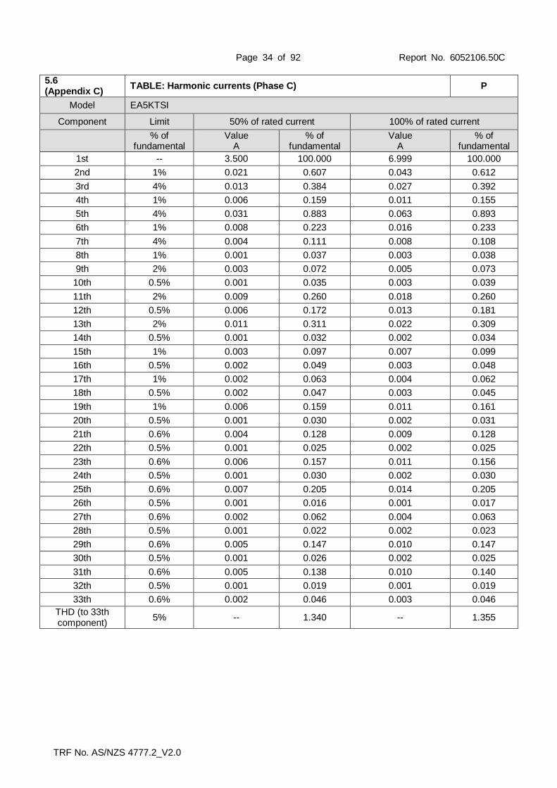
TABLE: Harmonic currents (Phase C) P
Model EA5KTSI
Component Limit 50% of rated current 100% of rated current
% of
fundamental Value
A % of
fundamental Value
A % of
fundamental
1st -- 3.500 100.000 6.999 100.000
2nd 1% 0.021 0.607 0.043 0.612
3rd 4% 0.013 0.384 0.027 0.392
4th 1% 0.006 0.159 0.011 0.155
5th 4% 0.031 0.883 0.063 0.893
6th 1% 0.008 0.223 0.016 0.233
7th 4% 0.004 0.111 0.008 0.108
8th 1% 0.001 0.037 0.003 0.038
9th 2% 0.003 0.072 0.005 0.073
10th 0.5% 0.001 0.035 0.003 0.039
11th 2% 0.009 0.260 0.018 0.260
12th 0.5% 0.006 0.172 0.013 0.181
13th 2% 0.011 0.311 0.022 0.309
14th 0.5% 0.001 0.032 0.002 0.034
15th 1% 0.003 0.097 0.007 0.099
16th 0.5% 0.002 0.049 0.003 0.048
17th 1% 0.002 0.063 0.004 0.062
18th 0.5% 0.002 0.047 0.003 0.045
19th 1% 0.006 0.159 0.011 0.161
20th 0.5% 0.001 0.030 0.002 0.031
21th 0.6% 0.004 0.128 0.009 0.128
22th 0.5% 0.001 0.025 0.002 0.025
23th 0.6% 0.006 0.157 0.011 0.156
24th 0.5% 0.001 0.030 0.002 0.030
25th 0.6% 0.007 0.205 0.014 0.205
26th 0.5% 0.001 0.016 0.001 0.017
27th 0.6% 0.002 0.062 0.004 0.063
28th 0.5% 0.001 0.022 0.002 0.023
29th 0.6% 0.005 0.147 0.010 0.147
30th 0.5% 0.001 0.026 0.002 0.025
31th 0.6% 0.005 0.138 0.010 0.140
32th 0.5% 0.001 0.019 0.001 0.019
33th 0.6% 0.002 0.046 0.003 0.046
THD (to 33th component)
5% -- 1.340 -- 1.355

Page 35 of 92 Report No. 6052106.50C
TRF No. AS/NZS 4777.2_V2.0
5.6 (Appendix C)
TABLE: Voltage harmonic limits of test grid(Phase A) P
Model EA5KTSI
Vrms 240 Vac
Frequency 50 Hz
Harmonics Harmonic Limits of Test Voltage (%)
Voltage Magnitude (V)
% of Fundamental Phase
1st -- 239.892 100.000 A
2nd 0.2% 0.013 0.005 A
3rd 0.9% 0.361 0.151 A
4th 0.2% 0.015 0.006 A
5th 0.4% 0.049 0.020 A
6th 0.2% 0.019 0.008 A
7th 0.3% 0.014 0.006 A
8th 0.2% 0.018 0.007 A
9th 0.2% 0.013 0.005 A
10th 0.2% 0.010 0.004 A
11th 0.1% 0.023 0.010 A
12th 0.1% 0.008 0.003 A
13th 0.1% 0.027 0.011 A
14th 0.1% 0.003 0.001 A
15th 0.1% 0.026 0.011 A
16th 0.1% 0.005 0.002 A
17th 0.1% 0.029 0.012 A
18th 0.1% 0.007 0.003 A
19th 0.1% 0.021 0.009 A
20th 0.1% 0.006 0.003 A
21th 0.1% 0.014 0.006 A
22th 0.1% 0.005 0.002 A
23th 0.1% 0.006 0.002 A
24th 0.1% 0.005 0.002 A
25th 0.1% 0.014 0.006 A
26th 0.1% 0.008 0.004 A
27th 0.1% 0.011 0.005 A
28th 0.1% 0.003 0.001 A
29th 0.1% 0.015 0.006 A
30th 0.1% 0.005 0.002 A
31th 0.1% 0.015 0.006 A
32th 0.1% 0.004 0.002 A
33th 0.1% 0.007 0.003 A
34th 0.1% 0.003 0.001 A
35th 0.1% 0.003 0.001 A
36th 0.1% 0.003 0.001 A
37th 0.1% 0.003 0.001 A
38th 0.1% 0.002 0.001 A
39th 0.1% 0.002 0.001 A
40th 0.1% 0.002 0.001 A
41th 0.1% 0.005 0.002 A
42th 0.1% 0.002 0.001 A
43th 0.1% 0.002 0.001 A
44th 0.1% 0.001 0.001 A
45th 0.1% 0.002 0.001 A
46th 0.1% 0.001 0.001 A
47th 0.1% 0.002 0.001 A

Page 36 of 92 Report No. 6052106.50C
TRF No. AS/NZS 4777.2_V2.0
48th 0.1% 0.001 0.000 A
49th 0.1% 0.002 0.001 A
50th 0.1% 0.001 0.000 A
THD (to 50th component)
5% -- 0.156 A
Supplementary information:
5.6 (Appendix C)
TABLE: Voltage harmonic limits of test grid(Phase B) P
Model EA5KTSI
Vrms 240 Vac
Frequency 50 Hz
Harmonics Harmonic Limits of Test Voltage (%)
Voltage Magnitude (V)
% of Fundamental Phase
1st -- 239.819 100.000 B
2nd 0.2% 0.006 0.003 B
3rd 0.9% 0.369 0.154 B
4th 0.2% 0.013 0.005 B
5th 0.4% 0.051 0.021 B
6th 0.2% 0.011 0.004 B
7th 0.3% 0.012 0.005 B
8th 0.2% 0.024 0.010 B
9th 0.2% 0.009 0.004 B
10th 0.2% 0.009 0.004 B
11th 0.1% 0.020 0.008 B
12th 0.1% 0.004 0.002 B
13th 0.1% 0.028 0.012 B
14th 0.1% 0.003 0.001 B
15th 0.1% 0.025 0.010 B
16th 0.1% 0.005 0.002 B
17th 0.1% 0.030 0.012 B
18th 0.1% 0.005 0.002 B
19th 0.1% 0.022 0.009 B
20th 0.1% 0.006 0.003 B
21th 0.1% 0.012 0.005 B
22th 0.1% 0.005 0.002 B
23th 0.1% 0.007 0.003 B
24th 0.1% 0.003 0.001 B
25th 0.1% 0.014 0.006 B
26th 0.1% 0.011 0.005 B
27th 0.1% 0.011 0.005 B
28th 0.1% 0.003 0.001 B
29th 0.1% 0.015 0.006 B
30th 0.1% 0.005 0.002 B
31th 0.1% 0.016 0.007 B
32th 0.1% 0.003 0.001 B
33th 0.1% 0.008 0.003 B
34th 0.1% 0.002 0.001 B
35th 0.1% 0.004 0.001 B
36th 0.1% 0.002 0.001 B
37th 0.1% 0.003 0.001 B
38th 0.1% 0.001 0.001 B

Page 37 of 92 Report No. 6052106.50C
TRF No. AS/NZS 4777.2_V2.0
39th 0.1% 0.003 0.001 B
40th 0.1% 0.001 0.001 B
41th 0.1% 0.005 0.002 B
42th 0.1% 0.001 0.001 B
43th 0.1% 0.003 0.001 B
44th 0.1% 0.001 0.001 B
45th 0.1% 0.003 0.001 B
46th 0.1% 0.001 0.001 B
47th 0.1% 0.002 0.001 B
48th 0.1% 0.001 0.001 B
49th 0.1% 0.002 0.001 B
50th 0.1% 0.001 0.001 B
THD (to 50th component)
5% -- 0.159 B
Supplementary information:
5.6 (Appendix C)
TABLE: Voltage harmonic limits of test grid(Phase C) P
Model EA5KTSI
Vrms 240 Vac
Frequency 50 Hz
Harmonics Harmonic Limits of Test Voltage (%)
Voltage Magnitude (V)
% of Fundamental Phase
1st -- 239.702 100.000 C
2nd 0.2% 0.008 0.003 C
3rd 0.9% 0.361 0.151 C
4th 0.2% 0.014 0.006 C
5th 0.4% 0.049 0.021 C
6th 0.2% 0.014 0.006 C
7th 0.3% 0.013 0.006 C
8th 0.2% 0.021 0.009 C
9th 0.2% 0.017 0.007 C
10th 0.2% 0.009 0.004 C
11th 0.1% 0.025 0.010 C
12th 0.1% 0.004 0.002 C
13th 0.1% 0.030 0.013 C
14th 0.1% 0.004 0.002 C
15th 0.1% 0.028 0.012 C
16th 0.1% 0.007 0.003 C
17th 0.1% 0.028 0.012 C
18th 0.1% 0.007 0.003 C
19th 0.1% 0.019 0.008 C
20th 0.1% 0.006 0.003 C
21th 0.1% 0.011 0.005 C
22th 0.1% 0.005 0.002 C
23th 0.1% 0.005 0.002 C
24th 0.1% 0.004 0.002 C
25th 0.1% 0.013 0.005 C
26th 0.1% 0.006 0.002 C
27th 0.1% 0.009 0.004 C
28th 0.1% 0.004 0.002 C
29th 0.1% 0.014 0.006 C
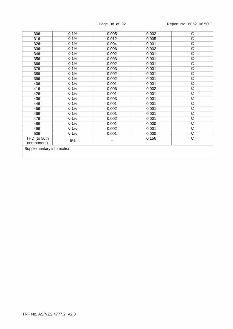
Page 38 of 92 Report No. 6052106.50C
TRF No. AS/NZS 4777.2_V2.0
30th 0.1% 0.005 0.002 C
31th 0.1% 0.012 0.005 C
32th 0.1% 0.004 0.001 C
33th 0.1% 0.006 0.002 C
34th 0.1% 0.002 0.001 C
35th 0.1% 0.003 0.001 C
36th 0.1% 0.002 0.001 C
37th 0.1% 0.003 0.001 C
38th 0.1% 0.002 0.001 C
39th 0.1% 0.002 0.001 C
40th 0.1% 0.001 0.001 C
41th 0.1% 0.006 0.002 C
42th 0.1% 0.001 0.001 C
43th 0.1% 0.003 0.001 C
44th 0.1% 0.001 0.001 C
45th 0.1% 0.002 0.001 C
46th 0.1% 0.001 0.001 C
47th 0.1% 0.002 0.001 C
48th 0.1% 0.001 0.000 C
49th 0.1% 0.002 0.001 C
50th 0.1% 0.001 0.000 C
THD (to 50th component)
5% -- 0.156 C
Supplementary information:

Page 39 of 92 Report No. 6052106.50C
TRF No. AS/NZS 4777.2_V2.0
5.6 (Appendix C)
TABLE: Harmonic currents (Phase A) P
Model EA16KTSI
Component Limit 50% of rated current 100% of rated current
% of
fundamental
Value A
% of fundamental
Value A
% of fundamental
1st -- 11.786 100.000 22.506 100.000
2nd 1% 0.057 0.485 0.099 0.438
3rd 4% 0.068 0.579 0.073 0.324
4th 1% 0.023 0.198 0.038 0.168
5th 4% 0.174 1.483 0.143 0.634
6th 1% 0.009 0.077 0.020 0.090
7th 4% 0.112 0.952 0.198 0.880
8th 1% 0.020 0.171 0.019 0.088
9th 2% 0.038 0.327 0.062 0.277
10th 0.5% 0.009 0.080 0.027 0.118
11th 2% 0.017 0.142 0.102 0.454
12th 0.5% 0.007 0.064 0.030 0.133
13th 2% 0.085 0.727 0.119 0.530
14th 0.5% 0.013 0.110 0.038 0.169
15th 1% 0.027 0.227 0.029 0.131
16th 0.5% 0.010 0.086 0.012 0.055
17th 1% 0.070 0.597 0.061 0.273
18th 0.5% 0.010 0.090 0.017 0.076
19th 1% 0.101 0.860 0.103 0.459
20th 0.5% 0.012 0.102 0.032 0.143
21th 0.6% 0.063 0.536 0.070 0.312
22th 0.5% 0.016 0.136 0.019 0.087
23th 0.6% 0.053 0.451 0.068 0.304
24th 0.5% 0.013 0.109 0.026 0.116
25th 0.6% 0.068 0.582 0.086 0.382
26th 0.5% 0.010 0.085 0.023 0.102
27th 0.6% 0.029 0.251 0.030 0.136
28th 0.5% 0.010 0.085 0.017 0.079
29th 0.6% 0.013 0.113 0.044 0.196
30th 0.5% 0.009 0.075 0.016 0.075
31th 0.6% 0.019 0.163 0.056 0.249
32th 0.5% 0.008 0.076 0.014 0.063
33th 0.6% 0.022 0.191 0.037 0.165
THD (to 33th component)
5% -- 2.694 -- 1.792

Page 40 of 92 Report No. 6052106.50C
TRF No. AS/NZS 4777.2_V2.0
5.6 (Appendix C)
TABLE: Harmonic current (Phase B) P
Model EA16KTSI
Component Limit 50% of rated current 100% of rated current
% of
fundamental
Value A
% of fundamental
Value A
% of fundamental
1st -- 11.490 100.000 22.163 100.000
2nd 1% 0.067 0.587 0.138 0.626
3rd 4% 0.114 0.995 0.126 0.572
4th 1% 0.064 0.561 0.076 0.345
5th 4% 0.194 1.696 0.138 0.626
6th 1% 0.021 0.188 0.024 0.110
7th 4% 0.117 1.025 0.148 0.669
8th 1% 0.023 0.204 0.029 0.132
9th 2% 0.038 0.339 0.056 0.253
10th 0.5% 0.009 0.078 0.019 0.088
11th 2% 0.043 0.376 0.126 0.572
12th 0.5% 0.008 0.072 0.016 0.072
13th 2% 0.054 0.475 0.069 0.314
14th 0.5% 0.015 0.136 0.045 0.202
15th 1% 0.023 0.205 0.021 0.096
16th 0.5% 0.015 0.137 0.017 0.077
17th 1% 0.049 0.431 0.087 0.396
18th 0.5% 0.015 0.135 0.021 0.097
19th 1% 0.057 0.503 0.094 0.426
20th 0.5% 0.012 0.106 0.032 0.148
21th 0.6% 0.050 0.435 0.057 0.258
22th 0.5% 0.016 0.146 0.022 0.099
23th 0.6% 0.060 0.526 0.100 0.452
24th 0.5% 0.016 0.139 0.040 0.184
25th 0.6% 0.014 0.124 0.039 0.177
26th 0.5% 0.015 0.136 0.045 0.206
27th 0.6% 0.030 0.264 0.026 0.119
28th 0.5% 0.012 0.108 0.022 0.099
29th 0.6% 0.022 0.198 0.048 0.219
30th 0.5% 0.009 0.083 0.014 0.066
31th 0.6% 0.023 0.203 0.048 0.217
32th 0.5% 0.008 0.078 0.013 0.059
33th 0.6% 0.013 0.115 0.017 0.078
THD (to 33th component)
5% -- 3.075 -- 1.842

Page 41 of 92 Report No. 6052106.50C
TRF No. AS/NZS 4777.2_V2.0
5.6 (Appendix C)
TABLE: Harmonic currents (Phase C) P
Model EA16KTSI
Component Limit 50% of rated current 100% of rated current
% of
fundamental
Value A
% of fundamental
Value A
% of fundamental
1st -- 11.838 100.000 22.493 100.000
2nd 1% 0.016 0.139 0.068 0.302
3rd 4% 0.175 1.484 0.190 0.848
4th 1% 0.048 0.407 0.039 0.175
5th 4% 0.168 1.423 0.137 0.610
6th 1% 0.014 0.121 0.042 0.188
7th 4% 0.144 1.220 0.237 1.054
8th 1% 0.017 0.144 0.019 0.085
9th 2% 0.065 0.555 0.112 0.499
10th 0.5% 0.008 0.071 0.013 0.058
11th 2% 0.032 0.278 0.122 0.544
12th 0.5% 0.006 0.057 0.021 0.093
13th 2% 0.085 0.725 0.107 0.476
14th 0.5% 0.009 0.084 0.026 0.117
15th 1% 0.046 0.392 0.041 0.185
16th 0.5% 0.010 0.090 0.014 0.066
17th 1% 0.102 0.864 0.079 0.355
18th 0.5% 0.011 0.096 0.019 0.085
19th 1% 0.083 0.706 0.094 0.421
20th 0.5% 0.011 0.098 0.025 0.115
21th 0.6% 0.036 0.314 0.074 0.330
22th 0.5% 0.013 0.110 0.018 0.083
23th 0.6% 0.067 0.569 0.086 0.385
24th 0.5% 0.015 0.131 0.029 0.132
25th 0.6% 0.066 0.562 0.063 0.281
26th 0.5% 0.014 0.124 0.040 0.180
27th 0.6% 0.055 0.468 0.039 0.175
28th 0.5% 0.011 0.098 0.019 0.087
29th 0.6% 0.022 0.191 0.035 0.159
30th 0.5% 0.008 0.070 0.017 0.079
31th 0.6% 0.013 0.113 0.048 0.212
32th 0.5% 0.009 0.077 0.015 0.065
33th 0.6% 0.029 0.251 0.047 0.213
THD (to 33th component)
5% -- 3.256 -- 2.073

Page 42 of 92 Report No. 6052106.50C
TRF No. AS/NZS 4777.2_V2.0
5.6 (Appendix C)
TABLE: Voltage harmonic limits of test grid (Phase A) P
Model EA16KTSI
Vrms 240 Vac
Frequency 50 Hz
Harmonics Harmonic Limits of Test Voltage (%)
Voltage Magnitude (V)
% of Fundamental Phase
1st -- 240.204 100.000 A
2nd 0.2% 0.005 0.002 A
3rd 0.9% 0.061 0.025 A
4th 0.2% 0.003 0.001 A
5th 0.4% 0.048 0.020 A
6th 0.2% 0.002 0.001 A
7th 0.3% 0.004 0.001 A
8th 0.2% 0.004 0.001 A
9th 0.2% 0.029 0.012 A
10th 0.2% 0.002 0.001 A
11th 0.1% 0.017 0.007 A
12th 0.1% 0.006 0.002 A
13th 0.1% 0.017 0.007 A
14th 0.1% 0.004 0.002 A
15th 0.1% 0.018 0.008 A
16th 0.1% 0.003 0.002 A
17th 0.1% 0.003 0.001 A
18th 0.1% 0.002 0.001 A
19th 0.1% 0.012 0.004 A
20th 0.1% 0.002 0.001 A
21th 0.1% 0.004 0.002 A
22th 0.1% 0.007 0.003 A
23th 0.1% 0.008 0.003 A
24th 0.1% 0.005 0.002 A
25th 0.1% 0.019 0.008 A
26th 0.1% 0.003 0.001 A
27th 0.1% 0.007 0.003 A
28th 0.1% 0.004 0.002 A
29th 0.1% 0.003 0.002 A
30th 0.1% 0.003 0.002 A
31th 0.1% 0.002 0.001 A
32th 0.1% 0.006 0.003 A
33th 0.1% 0.009 0.004 A
34th 0.1% 0.004 0.002 A
35th 0.1% 0.008 0.003 A
36th 0.1% 0.006 0.003 A
37th 0.1% 0.006 0.003 A
38th 0.1% 0.006 0.002 A
39th 0.1% 0.007 0.003 A
40th 0.1% 0.006 0.003 A
41th 0.1% 0.006 0.003 A
42th 0.1% 0.005 0.002 A
43th 0.1% 0.007 0.003 A
44th 0.1% 0.007 0.003 A
45th 0.1% 0.004 0.002 A
46th 0.1% 0.008 0.004 A
47th 0.1% 0.006 0.003 A

Page 43 of 92 Report No. 6052106.50C
TRF No. AS/NZS 4777.2_V2.0
48th 0.1% 0.006 0.003 A
49th 0.1% 0.006 0.003 A
50th 0.1% 0.008 0.004 A
THD (to 50th component)
5% -- 0.041 A
Supplementary information:
5.6 (Appendix C)
TABLE: Voltage harmonic limits of test grid (Phase B) P
Model EA16KTSI
Vrms 240 Vac
Frequency 50 Hz
Harmonics Harmonic Limits of Test Voltage (%)
Voltage Magnitude (V)
% of Fundamental Phase
1st -- 240.208 100.000 B
2nd 0.2% 0.013 0.005 B
3rd 0.9% 0.057 0.023 B
4th 0.2% 0.009 0.004 B
5th 0.4% 0.045 0.019 B
6th 0.2% 0.005 0.002 B
7th 0.3% 0.003 0.002 B
8th 0.2% 0.009 0.004 B
9th 0.2% 0.026 0.011 B
10th 0.2% 0.005 0.002 B
11th 0.1% 0.018 0.008 B
12th 0.1% 0.016 0.007 B
13th 0.1% 0.014 0.006 B
14th 0.1% 0.010 0.004 B
15th 0.1% 0.015 0.006 B
16th 0.1% 0.003 0.001 B
17th 0.1% 0.005 0.002 B
18th 0.1% 0.006 0.003 B
19th 0.1% 0.010 0.004 B
20th 0.1% 0.001 0.001 B
21th 0.1% 0.006 0.003 B
22th 0.1% 0.011 0.005 B
23th 0.1% 0.005 0.002 B
24th 0.1% 0.007 0.003 B
25th 0.1% 0.011 0.005 B
26th 0.1% 0.003 0.001 B
27th 0.1% 0.010 0.004 B
28th 0.1% 0.006 0.003 B
29th 0.1% 0.008 0.004 B
30th 0.1% 0.004 0.002 B
31th 0.1% 0.007 0.003 B
32th 0.1% 0.006 0.003 B
33th 0.1% 0.004 0.003 B
34th 0.1% 0.007 0.003 B
35th 0.1% 0.002 0.001 B
36th 0.1% 0.007 0.003 B
37th 0.1% 0.004 0.002 B
38th 0.1% 0.006 0.003 B

Page 44 of 92 Report No. 6052106.50C
TRF No. AS/NZS 4777.2_V2.0
39th 0.1% 0.001 0.001 B
40th 0.1% 0.006 0.002 B
41th 0.1% 0.004 0.002 B
42th 0.1% 0.011 0.005 B
43th 0.1% 0.004 0.002 B
44th 0.1% 0.007 0.003 B
45th 0.1% 0.003 0.001 B
46th 0.1% 0.004 0.002 B
47th 0.1% 0.008 0.003 B
48th 0.1% 0.005 0.002 B
49th 0.1% 0.009 0.004 B
50th 0.1% 0.001 0.001 B
THD (to 50th component)
5% -- 0.039 B
Supplementary information:
5.6 (Appendix C)
TABLE: Voltage harmonic limits of test grid (Phase C) P
Model EA16KTSI
Vrms 240 Vac
Frequency 50 Hz
Harmonics Harmonic Limits of Test Voltage (%)
Voltage Magnitude (V)
% of Fundamental Phase
1st -- 240.134 100.000 C
2nd 0.2% 0.008 0.003 C
3rd 0.9% 0.058 0.024 C
4th 0.2% 0.004 0.001 C
5th 0.4% 0.044 0.018 C
6th 0.2% 0.005 0.002 C
7th 0.3% 0.003 0.001 C
8th 0.2% 0.010 0.004 C
9th 0.2% 0.032 0.013 C
10th 0.2% 0.002 0.001 C
11th 0.1% 0.024 0.010 C
12th 0.1% 0.003 0.001 C
13th 0.1% 0.010 0.004 C
14th 0.1% 0.003 0.001 C
15th 0.1% 0.023 0.009 C
16th 0.1% 0.006 0.002 C
17th 0.1% 0.011 0.004 C
18th 0.1% 0.011 0.004 C
19th 0.1% 0.015 0.006 C
20th 0.1% 0.007 0.003 C
21th 0.1% 0.012 0.005 C
22th 0.1% 0.003 0.001 C
23th 0.1% 0.010 0.004 C
24th 0.1% 0.003 0.001 C
25th 0.1% 0.004 0.001 C
26th 0.1% 0.002 0.001 C
27th 0.1% 0.006 0.003 C
28th 0.1% 0.002 0.001 C
29th 0.1% 0.010 0.004 C

Page 45 of 92 Report No. 6052106.50C
TRF No. AS/NZS 4777.2_V2.0
30th 0.1% 0.003 0.001 C
31th 0.1% 0.009 0.004 C
32th 0.1% 0.002 0.001 C
33th 0.1% 0.007 0.003 C
34th 0.1% 0.005 0.002 C
35th 0.1% 0.002 0.001 C
36th 0.1% 0.006 0.002 C
37th 0.1% 0.002 0.001 C
38th 0.1% 0.007 0.003 C
39th 0.1% 0.002 0.001 C
40th 0.1% 0.010 0.004 C
41th 0.1% 0.001 0.001 C
42th 0.1% 0.009 0.004 C
43th 0.1% 0.002 0.001 C
44th 0.1% 0.007 0.003 C
45th 0.1% 0.003 0.001 C
46th 0.1% 0.008 0.003 C
47th 0.1% 0.006 0.003 C
48th 0.1% 0.005 0.002 C
49th 0.1% 0.008 0.003 C
50th 0.1% 0.005 0.002 C
THD (to 50th component)
5% -- 0.041 C
Supplementary information:

Page 46 of 92 Report No. 6052106.50C
TRF No. AS/NZS 4777.2_V2.0
5.7 TABLE: Voltage fluctuations and flicker P
Model EA5KTSI —
Parameter Measured value Limits
Phase A Phase B Phase C
dc (%) 0.133 0.164 0.142 3.3
dmax (%) 0.583 0.688 0.692 4.0
d(t) (ms) 0 0 0 500
Pst 0.574 0.586 0.566 1,0
Plt 0.570 0.590 0.570 0.65
Supplementary information:
The test inverters flicker level was found to be lower than the permissible limit as per AS/NZS 61000.3.3.
5.7 TABLE: Voltage fluctuations and flicker P
Model EA16KTSI —
Parameter Measured value Limits
Phase A Phase B Phase C
dc (%) 0.061 0.057 0.016 3.3
dmax (%) 0.078 0.083 0.045 4.0
d(t) (ms) 0 0 0 500
Pst 0.017 0.017 0.031 1,0
Plt 0.017 0.018 0.018 0.65
Supplementary information:
The test inverters flicker level was found to be lower than the permissible limit as per AS/NZS 61000.3.11.

Page 47 of 92 Report No. 6052106.50C
TRF No. AS/NZS 4777.2_V2.0
5.8
(Appendix D) TABLE: Transient voltage limits (Phase A) P
Model EA16KTSI
Duration
(s)
Instantaneous line to neutral voltage (V)
Limit 10% load 50% load 100% load
0.0002 910 0 0 0
0.0006 710 0 0 0
0.002 580 0 0 0
0.006 470 0 0 0
0.02 420 0 0 0
0.06 390 0.00112 0.00048 0.00208
0.2 390 0.00112 0.00048 0.00208
0.6 390 0.00112 0.00048 0.00208
Test procedure:
(a) The inverter shall be placed in a test circuit equivalent to that shown in Figure D1, with modification of the resistor value (R) if required (see Paragraph D1).
(b) Before the switch is opened, the voltage at the grid-interactive port of the inverter shall be maintained at the grid test voltage.
(c) The simulated source supply shall be varied until the apparent power output of the inverter equals 10 ±5% of its rated apparent power.
(d) The switch (S) shall be opened.
(e) The voltage across the grid-interactive port of the inverter shall be recorded at a sample frequency of at least 10 kHz.
(f) Steps (b) to (e) shall be repeated with the inverter operating at 50 ±5% and 100 ±5% of its rated current output.

Page 48 of 92 Report No. 6052106.50C
TRF No. AS/NZS 4777.2_V2.0
5.8
(Appendix D) TABLE: Transient voltage limits (Phase B) P
Model EA16KTSI
Duration
(s)
Instantaneous line to neutral voltage (V)
Limit 10% load 50% load 100% load
0.0002 910 0 0 0
0.0006 710 0 0 0
0.002 580 0 0 0
0.006 470 0 0 0
0.02 420 0 0 0
0.06 390 0.00128 0.00064 0.00224
0.2 390 0.00128 0.00064 0.00224
0.6 390 0.00128 0.00064 0.00224
Test procedure:
(a) The inverter shall be placed in a test circuit equivalent to that shown in Figure D1, with modification of the resistor value (R) if required (see Paragraph D1).
(b) Before the switch is opened, the voltage at the grid-interactive port of the inverter shall be maintained at the grid test voltage.
(c) The simulated source supply shall be varied until the apparent power output of the inverter equals 10 ±5% of its rated apparent power.
(d) The switch (S) shall be opened.
(e) The voltage across the grid-interactive port of the inverter shall be recorded at a sample frequency of at least 10 kHz.
(f) Steps (b) to (e) shall be repeated with the inverter operating at 50 ±5% and 100 ±5% of its rated current output.

Page 49 of 92 Report No. 6052106.50C
TRF No. AS/NZS 4777.2_V2.0
5.8
(Appendix D) TABLE: Transient voltage limits (Phase C) P
Model EA16KTSI
Duration
(s)
Instantaneous line to neutral voltage (V)
Limit 10% load 50% load 100% load
0.0002 910 0 0 0
0.0006 710 0 0 0
0.002 580 0 0 0
0.006 470 0 0 0
0.02 420 0 0 0
0.06 390 0.0311 0.00056 0.00192
0.2 390 0.0311 0.00056 0.00192
0.6 390 0.0311 0.00056 0.00192
Test procedure:
(a) The inverter shall be placed in a test circuit equivalent to that shown in Figure D1. with modification of the resistor value (R) if required (see Paragraph D1).
(b) Before the switch is opened, the voltage at the grid-interactive port of the inverter shall be maintained at the grid test voltage.
(c) The simulated source supply shall be varied until the apparent power output of the inverter equals 10 ±5% of its rated apparent power.
(d) The switch (S) shall be opened.
(e) The voltage across the grid-interactive port of the inverter shall be recorded at a sample frequency of at least 10 kHz.
(f) Steps (b) to (e) shall be repeated with the inverter operating at 50 ±5% and 100 ±5% of its rated current output.

Page 50 of 92 Report No. 6052106.50C
TRF No. AS/NZS 4777.2_V2.0
5.8 (Appendix D)
TABLE: Transient voltage limits (Phase A-B) P
Model EA16KTSI
Duration
(s)
Instantaneous line to line voltage (V)
Limit 10% load 50% load 100% load
0,0002 1580 0 0 0
0,0006 1240 0 0 0
0,002 1010 0 0 0
0,006 810 0 0 0
0,02 720 0 0.0062 0
0,06 670 0.0007 0.0132 0.0007
0,2 670 0.0007 0.0132 0.0007
0,6 670 0.0007 0.0132 0.0007
The procedure:
(g) The inverter shall be placed in a test circuit equivalent to that shown in Figure D1, with modification of the resistor value (R) if required (see Paragraph D1).
(h) Before the switch is opened, the voltage at the grid-interactive port of the inverter shall be maintained at the grid test voltage.
(i) The simulated source supply shall be varied until the apparent power output of the inverter equals 10 ±5% of its rated apparent power.
(j) The switch (S) shall be opened.
(k) The voltage across the grid-interactive port of the inverter shall be recorded at a sample frequency of at least 10 kHz.
(l) Steps (b) to (e) shall be repeated with the inverter operating at 50 ±5% and 100 ±5% of its rated current output.

Page 51 of 92 Report No. 6052106.50C
TRF No. AS/NZS 4777.2_V2.0
5.8 (Appendix D)
TABLE: Transient voltage limits (Phase B-C) P
Model EA16KTSI
Duration
(s)
Instantaneous line to line voltage (V)
Limit 10% load 50% load 100% load
0,0002 1580 0 0 0
0,0006 1240 0 0 0
0,002 1010 0 0 0
0,006 810 0 0 0
0,02 720 0 0 0
0,06 670 0.0008 0.0001 0.0027
0,2 670 0.0008 0.0001 0.0027
0,6 670 0.0008 0.0001 0.0027
The procedure:
(m) The inverter shall be placed in a test circuit equivalent to that shown in Figure D1, with modification of the resistor value (R) if required (see Paragraph D1).
(n) Before the switch is opened, the voltage at the grid-interactive port of the inverter shall be maintained at the grid test voltage.
(o) The simulated source supply shall be varied until the apparent power output of the inverter equals 10 ±5% of its rated apparent power.
(p) The switch (S) shall be opened.
(q) The voltage across the grid-interactive port of the inverter shall be recorded at a sample frequency of at least 10 kHz.
(r) Steps (b) to (e) shall be repeated with the inverter operating at 50 ±5% and 100 ±5% of its rated current output.
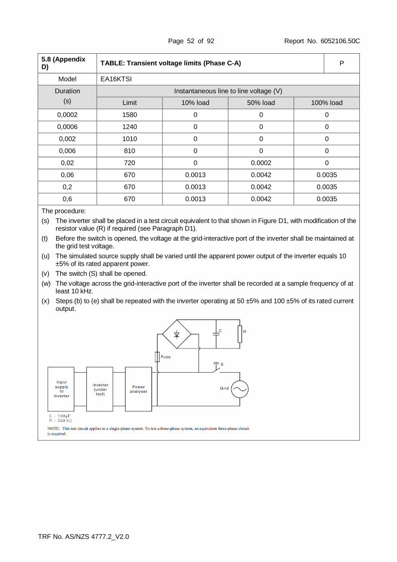
Page 52 of 92 Report No. 6052106.50C
TRF No. AS/NZS 4777.2_V2.0
5.8 (Appendix D)
TABLE: Transient voltage limits (Phase C-A) P
Model EA16KTSI
Duration
(s)
Instantaneous line to line voltage (V)
Limit 10% load 50% load 100% load
0,0002 1580 0 0 0
0,0006 1240 0 0 0
0,002 1010 0 0 0
0,006 810 0 0 0
0,02 720 0 0.0002 0
0,06 670 0.0013 0.0042 0.0035
0,2 670 0.0013 0.0042 0.0035
0,6 670 0.0013 0.0042 0.0035
The procedure:
(s) The inverter shall be placed in a test circuit equivalent to that shown in Figure D1, with modification of the resistor value (R) if required (see Paragraph D1).
(t) Before the switch is opened, the voltage at the grid-interactive port of the inverter shall be maintained at the grid test voltage.
(u) The simulated source supply shall be varied until the apparent power output of the inverter equals 10 ±5% of its rated apparent power.
(v) The switch (S) shall be opened.
(w) The voltage across the grid-interactive port of the inverter shall be recorded at a sample frequency of at least 10 kHz.
(x) Steps (b) to (e) shall be repeated with the inverter operating at 50 ±5% and 100 ±5% of its rated current output.

Page 53 of 92 Report No. 6052106.50C
TRF No. AS/NZS 4777.2_V2.0
5.9
(Appendix E) TABLE: D.C. current injection P
Model: EA16KTSI
Items 20% 60% 100%
Inverter output current, (A)
Setting 4.444 13.333 22.222
Actual 4.774 13.988 22.515
Limit, (A) 0.5%*Irated 0.111 0.111 0.111
Result Phase A D.C. injection, A 0.041 0.012 0.010
Result Phase B D.C. injection, A 0.039 0.032 0.032
Result Phase C D.C. injection, A 0.079 0.042 0.039
Compliance (P/F) P P P
Test procedure:
(a) Operate the inverter at 20% of its rated current and at rated power factor. The inverter shall operate for at least 5 min prior to taking any test measurements (or until the inverter temperature stabilizes). The inverter shall operate at the specified current for the period of the measurement
(b) At the inverter output, measure the r.m.s. voltage, r.m.s. current, and d.c. component (frequency less than 1Hz) of current on all phases. The average value of 180 consecutive readings of the d.c. component with a measurement period of 1 s for each reading shall be calculated. The inverter passes the requirement of this Standard if the average of the 180 consecutive readings is below the limit specified in Clause 5.9. For each 1 s sample, the absolute value (i.e. unsigned value) shall be used to calculate the 180 s average.
(c) Repeat Steps (a) and (b) with the inverter operating at 60% and 100% of its rated current.
(d) Divide the calculated average values for the magnitude of the d.c. component of current by the rated current of the inverter and derive the value of the d.c. current injection as a percentage. This shall be done for 3 test points (20%, 60% and 100%) and for each phase and/or neutral measurement. Record the final calculated values as the percentage of d.c. current injection for each phase.
Criteria for acceptance:
The measurement value including the grid-interactive and/or stand-alone port shall not exceed 0.5% of the inverter's rated current or 5 mA, whichever is the greater.

Page 54 of 92 Report No. 6052106.50C
TRF No. AS/NZS 4777.2_V2.0
5.9
(Appendix E) TABLE: D.C. current injection P
Model: EA5KTSI
Items 20% 60% 100%
Inverter output current, (A)
Setting 1.389 4.167 6.940
Actual 1.420 4.230 6.940
Limit, (A) 0.5%*Irated 0.035 0.035 0.035
Result L1 D.C. injection, A 0.013 0.013 0.013
Result L2 D.C. injection, A 0.011 0.011 0.011
Result L3 D.C. injection, A 0.004 0.004 0.004
Compliance (P/F) P P P
Test procedure:
(e) Operate the inverter at 20% of its rated current and at rated power factor. The inverter shall operate for at least 5 min prior to taking any test measurements (or until the inverter temperature stabilizes). The inverter shall operate at the specified current for the period of the measurement
(f) At the inverter output, measure the r.m.s. voltage, r.m.s. current, and d.c. component (frequency less than 1Hz) of current on all phases. The average value of 180 consecutive readings of the d.c. component with a measurement period of 1 s for each reading shall be calculated. The inverter passes the requirement of this Standard if the average of the 180 consecutive readings is below the limit specified in Clause 5.9. For each 1 s sample, the absolute value (i.e. unsigned value) shall be used to calculate the 180 s average.
(g) Repeat Steps (a) and (b) with the inverter operating at 60% and 100% of its rated current.
(h) Divide the calculated average values for the magnitude of the d.c. component of current by the rated current of the inverter and derive the value of the d.c. current injection as a percentage. This shall be done for 3 test points (20%, 60% and 100%) and for each phase and/or neutral measurement. Record the final calculated values as the percentage of d.c. current injection for each phase.
Criteria for acceptance:
The measurement value including the grid-interactive and/or stand-alone port shall not exceed 0.5% of the inverter's rated current or 5 mA, whichever is the greater.

Page 55 of 92 Report No. 6052106.50C
TRF No. AS/NZS 4777.2_V2.0
5.10 TABLE: Current balance for three-phase inverters P
Model EA16KTSI
Measurement No. 1 2 3 4 5
Test at rated current @ cos φ = 1
IE60 [A]: L1 22.364 22.362 22.356 22.355 22.371
IE60 [A]: L2 22.243 22.246 22.238 22.228 22.247
IE60 [A]: L3 22.415 22.423 22.423 22.416 22.432
IE60 [A]: |L1 - L2| 0.121 0.125 0.118 0.127 0.124
IE60 [A]: |L2 - L3| 0.172 0.189 0.185 0.188 0.185
IE60 [A]: |L3 - L1| 0.050 0.072 0.067 0.061 0.060
cos φE60 max.: 0.998
max unbalance current [A]: 0.185
Limit, 5% IRated [A]: 1.111
Supplementary information:
At the inverter output, measure the r.m.s. voltage, r.m.s. current of all phases. The average value of 300 consecutive readings of the output current with a measurement period of 1 s for each reading shall be calculated.
Criteria for acceptance:
The a.c. output current for each phase for three-phase balanced current shall be within 5% of the measured value of the other phases at rated current when injected into a balanced three phase voltage.

Page 56 of 92 Report No. 6052106.50C
TRF No. AS/NZS 4777.2_V2.0
6.3.2.2 TABLE: Volt-watt response mode P
Model EA16KTSI
Reference Vac Set point [V] Vac Measured
[V] P measured
[kW] P/Prated [%]
Max value (P/Prated) [%]
V1 207 207 16225.5 101.41 100%
V2 220 220 16006.3 100.04 100%
V3 250
(for Australia) 250 16075.9 100.47 100%
V3 244
(for New Zealand) 244 16160.2 101.00 100%
V4 265
(for Australia) 265 3253.9 20.34 20%
V4 255
(for New Zealand) 255 3282.8 20.51 20%
Supplementary information:
The volt-watt response mode varies the output power of the inverter in response to the voltage at its terminal. The inverter should have the volt-watt response mode.
The response curve required for the volt-watt response mode is defined by the volt response reference values in Table 9 and corresponding power levels. The default values are listed in Table 10 and example response modes are shown in Figure 2(A) for Australia and Figure 2(B) for New Zealand.

Page 57 of 92 Report No. 6052106.50C
TRF No. AS/NZS 4777.2_V2.0

Page 58 of 92 Report No. 6052106.50C
TRF No. AS/NZS 4777.2_V2.0
6.3.2.3 TABLE: Volt-var response mode P
Model EA16KTSI
Reference Vac Set point [V] Vac Measured
[V] Q measured
[kVar] Q/Srated [%]
Max value (Q/Srated) [%]
V1 207 206.8 4809.3 30.0 30% leading
V2 220 221.1 281.0 1.8 0
V3 250
(for Australia) 250.9 442.8 2.8 0
V3 244
(for New Zealand) 244.9 -149.4 -0.9 0
V4 265
(for Australia) 265.0 -4926.9 -30.8 30% lagging
V4 255
(for New Zealand) 255.2 -4950.6 -30.9 30% lagging
Supplementary information:
The volt-var response mode varies the reactive power output of the inverter in response to the voltage at its grid-interactive port. The inverter should have the volt-var response capability.
The response curve required for the volt-var response is defined by the volt response reference values specified in Table 9 and corresponding var levels. The default values are listed in Table 11 and shown in Figure 3.

Page 59 of 92 Report No. 6052106.50C
TRF No. AS/NZS 4777.2_V2.0

Page 60 of 92 Report No. 6052106.50C
TRF No. AS/NZS 4777.2_V2.0
6.3.2.4 TABLE: Voltage balance modes P
A voltage imbalance between phases may occur in an electrical installation that presents a load that is not balanced across the phases. Three-phase inverters, or single-phase inverters used in a three-phase combination may be used for voltage balancing between phases by injecting unbalanced three-phase currents into the electrical installation.
If the voltage balance mode is available, the following requirements apply:
P
(a) The voltage balance mode shall be disabled by default. P
(b) For single-phase inverters used in a three-phase combination, the requirements of Clause 8.2 apply.
N/A
(c) The voltage balancing mode shall be able to --
i. operate correctly with a single fault applied;
ii. detect the fault or loss of operability and cause the inverter to revert to injecting current into the three-phase electrical installation as a three-phase balanced current; or
iii. detect the fault or loss of operability and disconnect the inverter from the electrical installation.
P
Criteria for acceptance:
Compliance shall be determined by inspection.
P

Page 61 of 92 Report No. 6052106.50C
TRF No. AS/NZS 4777.2_V2.0
6.3.4 TABLE: Characteristic power factor curve for cos φ (P) (Power response) P
Model EA16KTSI
Mode Measurement 15% 25% 50% 75% 100%
Cos φ (P) mode - Lag
Power (watt) 2526.7 4146.4 8151.2 12127.8 15489.8
Reactive power (var) 366.1 349.2 309.6 2760.4 4858.5
PF cos (phi) 0.990 0.996 0.999 0.975 0.954
The procedure:
The response curve required for the cos φ (P) response should be defined within displacement power factor range of 0.9 leading to 0.9 lagging. One possible cos φ (P) curve is shown in Figure 4.
Criteria for acceptance:
The required accuracy for the measurement and reporting of results is ±0.01 PF. For testing at limits or in other modes, results shall be ±0.01 of the required limit, i.e. for a limit of 0.95, values equal to 0.94 to 0.96 are acceptable. When operating in this mode for all inverter current outputs below 25% of rated current, it is acceptable for the displacement power factor to be controlled such that the vars supplied or drawn are less than the amount of vars supplied or drawn at 25% current output.

Page 62 of 92 Report No. 6052106.50C
TRF No. AS/NZS 4777.2_V2.0
7.3 TABLE: Islanding protection - tested condition and run-on time – L1 phase P
No. PEUT (% of EUT rating)
Reactive load (%
of normial)
PAC QAC Run-on time (ms)
PEUT
(W) Actual
Qf
(kVar)
VDC Remark
Test condition A
1 100 100 0 0 263 5305 1.01 818 Test A at
BL
2 100 100 0 - 5 224 5317 0.97 818 Test A at
IB
3 100 100 0 + 5 285 5250 1.04 817 Test A at
IB
4 100 100 - 5 - 5 133 5216 1.04 817 Test A at
IB
5 100 100 - 5 0 210 5305 1.08 818 Test A at
IB
6 100 100 - 5 + 5 239 5351 1.11 817 Test A at
IB
7 100 100 + 5 - 5 124 5335 0.93 817 Test A at
IB
8 100 100 + 5 0 494 5323 0.97 817 Test A at
IB
9 100 100 + 5 + 5 253 5342 0.99 818 Test A at
IB
10 100 100 - 5 - 10 110 5337 1.00 817 Test A at
IB
11 100 100 - 5 + 10 170 5326 1.14 817 Test A at
IB
12 100 100 0 - 10 126 5310 0.94 817 Test A at
IB
13 100 100 0 + 10 176 5321 1.07 818 Test A at
IB
14 100 100 + 5 - 10 105 5330 0.90 817 Test A at
IB
15 100 100 + 5 + 10 138 5319 1.02 818 Test A at
IB
16 100 100 - 10 - 10 129 5318 1.06 818 Test A at
IB
17 100 100 - 10 - 5 137 5343 1.10 818 Test A at
IB
18 100 100 - 10 0 442 5337 1.14 818 Test A at
IB
19 100 100 - 10 + 5 593 5339 1.16 817 Test A at
IB
20 100 100 - 10 +10 209 5350 1.20 817 Test A at
IB
21 100 100 + 10 - 10 134 5344 0.85 817 Test A at
IB
22 100 100 + 10 - 5 175 5364 0.88 817 Test A at
IB
23 100 100 + 10 0 214 5322 0.93 818 Test A at
IB
24 100 100 + 10 + 5 370 5355 0.94 818 Test A at
IB
25 100 100 + 10 + 10 177 5341 0.98 818 Test A at
IB
Test condition B

Page 63 of 92 Report No. 6052106.50C
TRF No. AS/NZS 4777.2_V2.0
1 66 66 0 - 5 382 3441 0.95 673 Test B at
IB
2 66 66 0 - 4 341 3451 0.96 674 Test B at
IB
3 66 66 0 - 3 553 3455 0.96 673 Test B at
IB
4 66 66 0 - 2 247 3464 0.98 673 Test B at
IB
5 66 66 0 - 1 353 3468 0.99 673 Test B at
IB
6 66 66 0 0 549 3470 1.00 673 Test B at
BL
7 66 66 0 + 1 312 3477 1.00 673 Test B at
IB
8 66 66 0 + 2 233 3465 1.00 673 Test B at
IB
9 66 66 0 + 3 473 3448 1.00 673 Test B at
IB
10 66 66 0 + 4 214 3473 1.01 674 Test B at
IB
11 66 66 0 + 5 174 3455 1,02 674 Test B at
IB
Test condition C
1 33 33 0 - 5 420 1791 0.98 447 Test C at IB
2 33 33 0 - 4 602 1789 0.96 448 Test C at IB
3 33 33 0 - 3 382 1796 0.97 448 Test C at IB
4 33 33 0 - 2 443 1787 0.97 448 Test C at IB
5 33 33 0 - 1 503 1794 0.98 448 Test C at IB
6 33 33 0 0 220 1791 1.00 448 Test C at BL
7 33 33 0 + 1 203 1792 1.02 449 Test C at IB
8 33 33 0 + 2 239 1795 1.02 448 Test C at IB
9 33 33 0 + 3 322 1793 1.03 448 Test C at IB
10 33 33 0 + 4 187 1794 1.04 448 Test C at IB
11 33 33 0 + 5 162 1794 1.07 448 Test C at IB
Remark: For test condition A: If any of the recorded run-on times are longer than the one recorded for the rated balance condition, then the non-shaded parameter combinations also require testing. For test condition B and C: If run-on times are still increasing at the 95 % or 105 % points, additional 1 % increments is taken until run-on times begin decreasing. The tests were performed on model EA16KTSI also applicable for all other models stated in this report.

Page 64 of 92 Report No. 6052106.50C
TRF No. AS/NZS 4777.2_V2.0
Graph of disconnection at PAC -10% and QAC +5% reactive load and 100% nominal power
Graph of disconnection at PAC 0% and QAC -3% reactive load and 66% nominal power

Page 65 of 92 Report No. 6052106.50C
TRF No. AS/NZS 4777.2_V2.0
Graph of disconnection at PAC 0% and QAC -4% reactive load and 33% nominal power
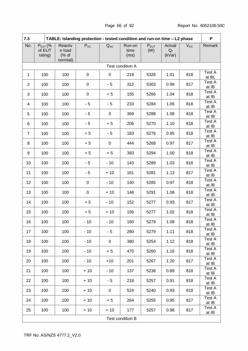
Page 66 of 92 Report No. 6052106.50C
TRF No. AS/NZS 4777.2_V2.0
7.3 TABLE: Islanding protection - tested condition and run-on time – L2 phase P
No. PEUT (% of EUT rating)
Reactive load (% of
normial)
PAC QAC Run-on time (ms)
PEUT
(W) Actual
Qf
(kVar)
VDC Remark
Test condition A
1 100 100 0 0 219 5326 1.01 818 Test A at BL
2 100 100 0 - 5 312 5303 0.99 817 Test A at IB
3 100 100 0 + 5 155 5266 1.04 818 Test A at IB
4 100 100 - 5 - 5 233 5284 1.05 818 Test A at IB
5 100 100 - 5 0 369 5288 1.08 818 Test A at IB
6 100 100 - 5 + 5 206 5270 1.10 818 Test A at IB
7 100 100 + 5 - 5 183 5276 0.95 818 Test A at IB
8 100 100 + 5 0 444 5268 0.97 817 Test A at IB
9 100 100 + 5 + 5 393 5294 1.00 818 Test A at IB
10 100 100 - 5 - 10 143 5289 1.03 818 Test A at IB
11 100 100 - 5 + 10 161 5281 1.13 817 Test A at IB
12 100 100 0 - 10 140 5285 0.97 818 Test A at IB
13 100 100 0 + 10 148 5291 1.08 818 Test A at IB
14 100 100 + 5 - 10 152 5277 0.93 817 Test A at IB
15 100 100 + 5 + 10 156 5277 1.02 818 Test A at IB
16 100 100 - 10 - 10 160 5279 1.08 818 Test A at IB
17 100 100 - 10 - 5 280 5279 1.11 818 Test A at IB
18 100 100 - 10 0 380 5254 1.12 818 Test A at IB
19 100 100 - 10 + 5 470 5260 1.16 818 Test A at IB
20 100 100 - 10 +10 201 5267 1.20 817 Test A at IB
21 100 100 + 10 - 10 137 5238 0.89 818 Test A at IB
22 100 100 + 10 - 5 218 5257 0.91 818 Test A at IB
23 100 100 + 10 0 524 5240 0.93 818 Test A at IB
24 100 100 + 10 + 5 264 5255 0.95 817 Test A at IB
25 100 100 + 10 + 10 177 5257 0.98 817 Test A at IB
Test condition B

Page 67 of 92 Report No. 6052106.50C
TRF No. AS/NZS 4777.2_V2.0
1 66 66 0 - 5 358 3529 0.98 673 Test B at IB
2 66 66 0 - 4 365 3549 0.98 674 Test B at IB
3 66 66 0 - 3 242 3546 0.99 673 Test B at IB
4 66 66 0 - 2 529 3537 0.99 673 Test B at IB
5 66 66 0 - 1 363 3555 1.00 673 Test B at IB
6 66 66 0 0 467 3543 1.00 674 Test B at BL
7 66 66 0 + 1 293 3534 1.01 673 Test B at IB
8 66 66 0 + 2 273 3549 1.01 673 Test B at IB
9 66 66 0 + 3 224 3537 1.01 673 Test B at IB
10 66 66 0 + 4 278 3553 1.02 673 Test B at IB
11 66 66 0 + 5 272 3553 1.02 673 Test B at IB
Test condition C
1 33 33 0 - 5 509 1770 0.98 448 Test C at IB
2 33 33 0 - 4 425 1772 0.98 449 Test C at IB
3 33 33 0 - 3 546 1773 0.99 448 Test C at IB
4 33 33 0 - 2 409 1776 1.00 448 Test C at IB
5 33 33 0 - 1 396 1775 1.00 449 Test C at IB
6 33 33 0 0 374 1773 1.00 448 Test C at BL
7 33 33 0 + 1 364 1777 1.01 448 Test C at IB
8 33 33 0 + 2 292 1776 1.02 448 Test C at IB
9 33 33 0 + 3 258 1776 1.02 449 Test C at IB
10 33 33 0 + 4 258 1779 1.02 448 Test C at IB
11 33 33 0 + 5 164 1777 1.03 448 Test C at IB
Remark: For test condition A: If any of the recorded run-on times are longer than the one recorded for the rated balance condition, then the non-shaded parameter combinations also require testing. For test condition B and C: If run-on times are still increasing at the 95 % or 105 % points, additional 1 % increments is taken until run-on times begin decreasing. The tests were performed on model EA16KTSI also applicable for all other models stated in this report.

Page 68 of 92 Report No. 6052106.50C
TRF No. AS/NZS 4777.2_V2.0
Graph of disconnection at PAC +10% and QAC 0% reactive load and 100% nominal power
Graph of disconnection at PAC 0% and QAC -2% reactive load and 66% nominal power

Page 69 of 92 Report No. 6052106.50C
TRF No. AS/NZS 4777.2_V2.0
Graph of disconnection at PAC 0% and QAC -3% reactive load and 33% nominal power
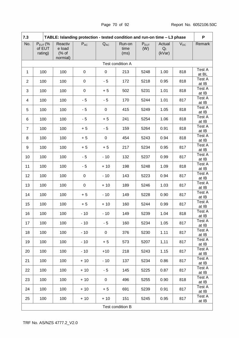
Page 70 of 92 Report No. 6052106.50C
TRF No. AS/NZS 4777.2_V2.0
7.3 TABLE: Islanding protection - tested condition and run-on time – L3 phase P
No. PEUT (% of EUT rating)
Reactive load (% of
normial)
PAC QAC Run-on time (ms)
PEUT
(W) Actual
Qf
(kVar)
VDC Remark
Test condition A
1 100 100 0 0 213 5248 1.00 818 Test A at BL
2 100 100 0 - 5 172 5218 0.95 818 Test A at IB
3 100 100 0 + 5 502 5231 1.01 818 Test A at IB
4 100 100 - 5 - 5 170 5244 1.01 817 Test A at IB
5 100 100 - 5 0 415 5249 1.05 818 Test A at IB
6 100 100 - 5 + 5 241 5254 1.06 818 Test A at IB
7 100 100 + 5 - 5 159 5264 0.91 818 Test A at IB
8 100 100 + 5 0 454 5243 0.94 818 Test A at IB
9 100 100 + 5 + 5 217 5234 0.95 817 Test A at IB
10 100 100 - 5 - 10 132 5237 0.99 817 Test A at IB
11 100 100 - 5 + 10 198 5248 1.09 818 Test A at IB
12 100 100 0 - 10 143 5223 0.94 817 Test A at IB
13 100 100 0 + 10 189 5246 1.03 817 Test A at IB
14 100 100 + 5 - 10 149 5228 0.90 817 Test A at IB
15 100 100 + 5 + 10 160 5244 0.99 817 Test A at IB
16 100 100 - 10 - 10 149 5239 1.04 818 Test A at IB
17 100 100 - 10 - 5 160 5234 1.05 817 Test A at IB
18 100 100 - 10 0 376 5230 1.11 817 Test A at IB
19 100 100 - 10 + 5 573 5207 1,11 817 Test A at IB
20 100 100 - 10 +10 218 5243 1.15 817 Test A at IB
21 100 100 + 10 - 10 137 5234 0.86 817 Test A at IB
22 100 100 + 10 - 5 145 5225 0.87 817 Test A at IB
23 100 100 + 10 0 496 5255 0.90 818 Test A at IB
24 100 100 + 10 + 5 691 5239 0.91 817 Test A at IB
25 100 100 + 10 + 10 151 5245 0.95 817 Test A at IB
Test condition B

Page 71 of 92 Report No. 6052106.50C
TRF No. AS/NZS 4777.2_V2.0
1 66 66 0 - 5 303 3515 0.95 673 Test B at IB
2 66 66 0 - 4 327 3526 0.95 673 Test B at IB
3 66 66 0 - 3 347 3532 0.96 673 Test B at IB
4 66 66 0 - 2 216 3519 0.97 674 Test B at IB
5 66 66 0 - 1 482 3549 0.98 673 Test B at IB
6 66 66 0 0 165 3523 1.01 673 Test B at BL
7 66 66 0 + 1 220 3546 1.01 673 Test B at IB
8 66 66 0 + 2 324 3531 1.01 673 Test B at IB
9 66 66 0 + 3 311 3540 1.01 673 Test B at IB
10 66 66 0 + 4 169 3543 1.01 673 Test B at IB
11 66 66 0 + 5 180 3545 1.02 673 Test B at IB
Test condition C
1 33 33 0 - 5 170 1756 0.99 448 Test C at IB
2 33 33 0 - 4 217 1767 0.99 448 Test C at IB
3 33 33 0 - 3 230 1768 0.99 448 Test C at IB
4 33 33 0 - 2 498 1771 0.99 448 Test C at IB
5 33 33 0 - 1 490 1749 0.99 448 Test C at IB
6 33 33 0 0 394 1771 1.01 448 Test C at BL
7 33 33 0 + 1 307 1765 1.02 448 Test C at IB
8 33 33 0 + 2 188 1776 1,03 448 Test C at IB
9 33 33 0 + 3 253 1770 1.04 448 Test C at IB
10 33 33 0 + 4 157 1758 1.07 448 Test C at IB
11 33 33 0 + 5 165 1770 1.08 448 Test C at IB
Remark: For test condition A: If any of the recorded run-on times are longer than the one recorded for the rated balance condition, then the non-shaded parameter combinations also require testing. For test condition B and C: If run-on times are still increasing at the 95 % or 105 % points, additional 1 % increments is taken until run-on times begin decreasing. The tests were performed on model EA16KTSI also applicable for all other models stated in this report.

Page 72 of 92 Report No. 6052106.50C
TRF No. AS/NZS 4777.2_V2.0
Graph of disconnection at PAC +10% and QAC +5% reactive load and 100% nominal power
Graph of disconnection at PAC 0% and QAC -1% reactive load and 66% nominal power

Page 73 of 92 Report No. 6052106.50C
TRF No. AS/NZS 4777.2_V2.0
Graph of disconnection at PAC 0% and QAC -2% reactive load and 33% nominal power

Page 74 of 92 Report No. 6052106.50C
TRF No. AS/NZS 4777.2_V2.0
7.4 & 7.7 (Appendix G)
TABLE: Undervoltage and overvoltage trip test & Connection and reconnection procedure
P
Model EA16KTSI
Test condition: Output level: 50 ± 5% of its rated current output Frequency: 50 Hz
Phase Voltage limit
[V] Actual
setting [V] Trip value
[V] Disconnection
time [s] Trip time limit
[s]
Phase A
260 (overvoltage–stage
1) 260
258.5 1.172
1-2 259.5 1.064
258.5 1.122
265 (overvoltage–stage
2) 265
263.5 0.160
0.2 264.5 0.127
263.5 0.152
180 (undervoltage)
180
178.5 1.017
1-2 179.0 1.260
178.5 1.240
Phase B
260 (overvoltage–stage
1) 260
259.5 1.182
1-2 259.5 1.139
259.5 1.214
265 (overvoltage–stage
2) 265
264.5 0.160
0.2 264.5 0.127
264.5 0.127
180 (undervoltage)
180
179.0 1.077
1-2 179.1 1.052
179.3 1.319
Phase C
260 (overvoltage–stage
1) 260
258.5 1.069
1-2 258.5 1.204
258.5 1.154
265 (overvoltage–stage
2) 265
263.5 0.123
0.2 263.5 0.143
263.5 0.187
180 (undervoltage)
180
178.5 1.572
1-2 178.5 1.654
178.5 1.819
Reconnection time limit: >60 s

Page 75 of 92 Report No. 6052106.50C
TRF No. AS/NZS 4777.2_V2.0
Disconnection time [s]

Page 76 of 92 Report No. 6052106.50C
TRF No. AS/NZS 4777.2_V2.0
7.4 (Appendix G) TABLE: Under-frequency and over-frequency trip test & Connection and reconnection procedure
P
Model EA16KTSI
Test condition: Output level: 50 ±5% of its rated output or 10 A, whichever is the lesser. Voltage: 230 Vac
Frequency limit [Hz]
Actual setting [Hz]
Trip value [Hz]
Disconnection time [s] Limit (range)
[s]
47 Hz (under-frequency
for Australia) 47
47 1.180
1 - 2 47 1.088
47 1.151
45 Hz (under-frequency for New Zealand)
45
45 1.176
1 - 2 45 1.136
45 1.154
52 Hz over-frequency
52
52 0.129
0.2 52 0.141
52 0.177
Test procedure:
1. The protective function limit, the trip delay time and disconnection time for the protective function under-frequency (F<) of Table 13 (i.e. 47Hz or 45Hz) of the automatic disconnection device shall be confirmed. The frequency of the variable a.c. supply shall be adjusted slowly to decrease the frequency until the device under test disconnects from the variable a.c. supply. The frequency at which disconnection occurs shall be recorded. The output frequency of the variable a.c. supply shall be set to a frequency equal to the under-frequency (F<) limit, as recorded plus 0.1 Hz. The frequency shall then be decreased as rapidly as possible but at a rate less than any df/dt protection incorporated in the device under test. The time interval between the frequency passing through t he frequency measured trip value and the device under test disconnecting from the variable a.c. supply shall be recorded.
2. The trip frequency and the disconnection time for the protective function over frequency (F>) of Table 13 (i.e. 52 Hz) limit of the automatic disconnection device shall be conf irmed. The frequency of the variable a.c. supply shall be adjusted slowly to increase the frequency until the device under test disconnects from the variable a.c. supply. The frequency at which disconnection occurs shall be recorded. The output frequency of the variable a.c. supply shall be set to a frequency equal to the over-frequency (F>) limit, as recorded minus 0.1 Hz. The frequency shall then be increased as rapidly as possible but at a rate less than any df/dt protection incorporated in the device under test. The time interval between the frequency passing through the frequency measured trip value and the device under test disconnecting from the variable a.c. supply shall be recorded.
Criteria for acceptance:
When subjected to the tests specified in Paragraph G3.2, the device under test shall comply with the following:
(a) The frequency recorded for the under-frequency (F<) limit shall equal 47 ±0.1 Hz. The disconnection time recorded shall be greater than the trip delay time of 1 s, and the disconnection time shall be less than 2 s. NOTE: For New Zealand, 45Hz.
(b) The frequency recorded for the over-frequency (F>) limit shall equal 52 ±0.1 Hz. The disconnection time recorded shall be less than 0.2 s.
(c) The reconnection times recorded shall each be 60 s or greater.

Page 77 of 92 Report No. 6052106.50C
TRF No. AS/NZS 4777.2_V2.0
7.5.2 (Appendix H2) TABLE: Sustained operation for voltage variations P
Model EA16KTSI
Setpoint Vnom-max for Australia: 255 Vac
Setpoint Vnom-max for New Zealand: 246 Vac
Step Test result
Limit Australia New Zealand
(a-f)
The average voltage shall be recorded at the a.c terminals of the device under test such that the average value for the preceding 10 min can be calculated when the device under test disconnects.
Phase 1 255.3 Vac 246.7 Vac the average of the value for Vnom-max determined shall equal the set-point ±1%.
Phase 2 255.5 Vac 246.6 Vac
Phase 3 255.3 Vac 246.8 Vac
(h)
The voltage shall be set to a voltage equal to the Vnom-max setting (i.e. 255 V for Australia, 246V for New Zealand) and This voltage level shall be maintained for 10 min.
Phase 1 255.3 Vac 246.7 Vac
Disconnection should not take place.
Phase 2 255.4 Vac 246.7 Vac
Phase 3 255.3 Vac 246.8 Vac
(i)
The output voltage of the variable a.c. supply shall be increased by 2 V (i.e. Vnom-max setting plus 2 V).
Phase 1 28.9 s 23.1 s The disconnect time as recorded shall be less than 30 s.
Phase 2 17.3 s 12.9 s
Phase 3 29.2 s 27.2 s
(j)
The output voltage of the variable a.c. supply shall be decreased so that the voltage at the a.c terminals of the device under test equals the grid test voltage.
Phase 1 181.8 s 170.1 s The time to reconnect recorded shall be greater than 60 s.
Phase 2 187.3 s 170.4 s
Phase 3 192.8 s 177.2 s
Test procedure:
(a) The inverter and automatic disconnection device shall be connected into a test circuit equivalent to that shown in Figure G1.

Page 78 of 92 Report No. 6052106.50C
TRF No. AS/NZS 4777.2_V2.0
(b) The sustained operation over-voltage limit (Vnom-max) as specified in Clause 7.5.2, shall be confirmed (i.e. Vnom-max shall be 255 V or 246 V).
(c) The variable a.c. supply shall be set so that the voltage at the a.c terminals of the device under test equals the grid test voltage. The input supply shall be varied until the a.c. output of the device under test equals 50 ±5% of its rated apparent power.
(d) The output voltage of the variable a.c. supply shall be set to a voltage equal to the Vnom-max setting less 1 V. This voltage level shall be maintained for 5 min.
(e) The output voltage of the variable a.c. supply shall be increased by 2 V (i.e. Vnom-max setting plus 1V).
(f) The average voltage shall be recorded at the a.c terminals of the device under test such that the average value for the preceding 10 min can be calculated when the device under test disconnects.
(g) The variable a.c. supply shall be adjusted to return the voltage at the a.c. terminals of the device under test to the grid test voltage.
(h) After the set-point has been determined, the output voltage of the variable a.c. supply shall be set to a voltage equal to the Vnom-max setting. This voltage level shall be maintained for 10 min.
(i) The output voltage of the variable a.c. supply shall be increased by 2 V (i.e. Vnom-max setting plus 2 V). The time to disconnect shall be recorded.
(j) The output voltage of the variable a.c. supply shall be decreased so that the voltage at the a.c terminals of the device under test equals the grid test voltage. The time to reconnect shall be recorded.
Criteria for acceptance
When subjected to the test specified above, the average of the value for Vnom-max determined in Step (f) shall equal the set-point ±1%. The time to detect a sustained overvoltage and disconnect as recorded in Step (i) shall be less than 30 s. The time to reconnect recorded in Step (j) shall be greater than 60 s.

Page 79 of 92 Report No. 6052106.50C
TRF No. AS/NZS 4777.2_V2.0
7.5.3.1 (Appendix H3)
TABLE: Response to an increase infrequency P
Model EA16KTSI
Measurement (a) to (n): Active power output 50% Pn
Sn [kVA]: 16.000 Pref [kW] 8.000
Set point frequency Measuring frequency
value [Hz] Psetpoint [kW] PE30 [kW] ΔPE30/Pn [%]
Step (f)
50.20 Hz 50.20 8.000 8.134 0.81
50.30 Hz 50.29 7.771 7.825 0.34
50.40 Hz 50.40 7.314 7.405 0.58
50.50 Hz 50.49 6.857 6.917 0.38
50.60 Hz 50.60 6.400 6.474 0.46
50.70 Hz 50.70 5.942 6.005 0.39
50.80 Hz 50.80 5.485 5.560 0.47
50.90 Hz 50.89 5.028 5.112 0.53
51.00 Hz 50.99 4.571 4.640 0.41
51.10 Hz 51.09 4.114 4.190 0.41
51.20 Hz 51.19 3.657 3.694 0.24
51.30 Hz 51.29 3.200 3.258 0.36
51.40 Hz 51.39 2.742 2.772 0.18
51.50 Hz 51.50 2.285 2.339 0.33
51.60 Hz 51.60 1.829 1.867 0.24
51.70 Hz 51.70 1.371 1.399 0.16
51.80 Hz 51.79 0.914 0.952 0.24
51.90 Hz 51.89 0.457 0.504 0.29
52.00 Hz 52.00 0.000 0.001 0.08
52.10 Hz 52.09 0.000 0.001 0.08
52.20 Hz 52.20 0.000 0.001 0.01
Step (h)
52.00Hz 51.99 0.000 0.000 0.09
51.80Hz 51.79 0.000 0.000 0.09
51.60Hz 51.59 0.000 0.000 0.09
51.40Hz 51.39 0.000 0.000 0.10
51.20Hz 51.19 0.000 0.000 0.10
51.00Hz 50.99 0.000 0.000 0.10
50.80Hz 50.79 0.000 0.000 0.11
50.60Hz 50.60 0.000 0.000 0.11
50.40Hz 50.39 0.000 0.000 0.11
50.20Hz 50.19 0.000 0.000 0.11
50.00Hz 50.00 0.000 0.000 0.11
Step (i) 50.00 Hz 50.00 8.000 8.001 0.44
Step (k) 50.00 Hz 50.00 8.000 8.001 0.81
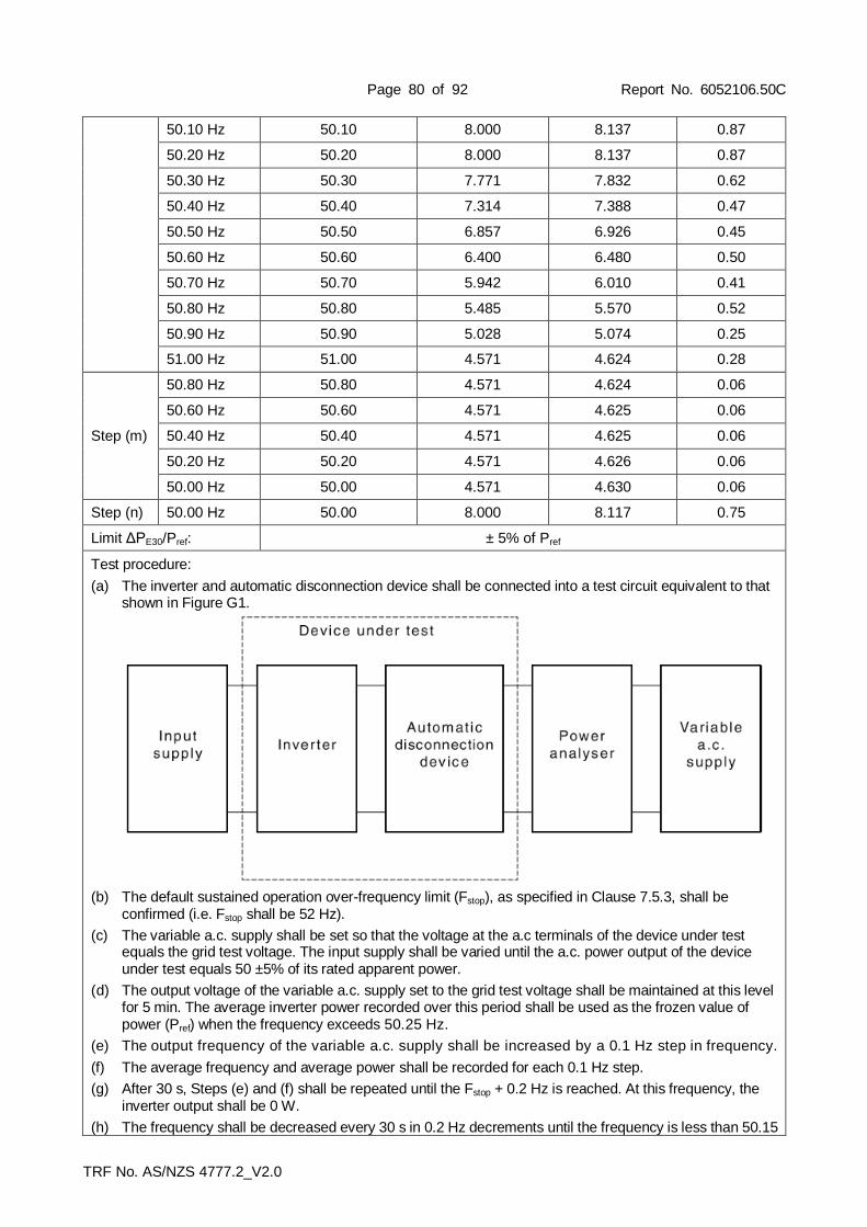
Page 80 of 92 Report No. 6052106.50C
TRF No. AS/NZS 4777.2_V2.0
50.10 Hz 50.10 8.000 8.137 0.87
50.20 Hz 50.20 8.000 8.137 0.87
50.30 Hz 50.30 7.771 7.832 0.62
50.40 Hz 50.40 7.314 7.388 0.47
50.50 Hz 50.50 6.857 6.926 0.45
50.60 Hz 50.60 6.400 6.480 0.50
50.70 Hz 50.70 5.942 6.010 0.41
50.80 Hz 50.80 5.485 5.570 0.52
50.90 Hz 50.90 5.028 5.074 0.25
51.00 Hz 51.00 4.571 4.624 0.28
Step (m)
50.80 Hz 50.80 4.571 4.624 0.06
50.60 Hz 50.60 4.571 4.625 0.06
50.40 Hz 50.40 4.571 4.625 0.06
50.20 Hz 50.20 4.571 4.626 0.06
50.00 Hz 50.00 4.571 4.630 0.06
Step (n) 50.00 Hz 50.00 8.000 8.117 0.75
Limit ΔPE30/Pref: ± 5% of Pref
Test procedure:
(a) The inverter and automatic disconnection device shall be connected into a test circuit equivalent to that shown in Figure G1.
(b) The default sustained operation over-frequency limit (Fstop), as specified in Clause 7.5.3, shall be confirmed (i.e. Fstop shall be 52 Hz).
(c) The variable a.c. supply shall be set so that the voltage at the a.c terminals of the device under test equals the grid test voltage. The input supply shall be varied until the a.c. power output of the device under test equals 50 ±5% of its rated apparent power.
(d) The output voltage of the variable a.c. supply set to the grid test voltage shall be maintained at this level for 5 min. The average inverter power recorded over this period shall be used as the frozen value of power (Pref) when the frequency exceeds 50.25 Hz.
(e) The output frequency of the variable a.c. supply shall be increased by a 0.1 Hz step in frequency.
(f) The average frequency and average power shall be recorded for each 0.1 Hz step.
(g) After 30 s, Steps (e) and (f) shall be repeated until the Fstop + 0.2 Hz is reached. At this frequency, the inverter output shall be 0 W.
(h) The frequency shall be decreased every 30 s in 0.2 Hz decrements until the frequency is less than 50.15

Page 81 of 92 Report No. 6052106.50C
TRF No. AS/NZS 4777.2_V2.0
Hz.
(i) The voltage and frequency shall be maintained for 10 min or until the inverter reaches the maximum output power available. The increase in power shall be monitored to determine if the controlled increase in power exceeds the power rate limit (WGra) of Clause 6.2.5.2.
(j) Steps (c) and (d) shall be repeated for the testing of the hysteresis when frequency does not exceed Fstop.
(k) After 30 s, Steps (e) and (f) shall be repeated until the 51.0 Hz is reached.
(l) The average frequency and average power shall be recorded.
(m) The frequency shall be decreased every 30 s in 0.2 Hz decrements until the frequency is less than 50.15 Hz. The average frequency and average power shall be recorded for each 0.2 Hz decrement.
(n) The voltage and frequency shall be maintained for 10 min or until the inverter reaches the maximum output power available. The increase in power shall be monitored to determine if the controlled increase in power exceeds the power rate limit (WGra) of Clause 6.2.5.2.
Criteria for acceptance:
When subjected to the tests specified in Paragraph H3.2, the response to the over-frequency condition shall be linear and in accordance with Clause 7.5.3.
The results recorded in Steps (f) and (k) shall be graphed on an x-y axis graph, where the x axis is frequency and the y axis is power output.
The results monitored in Steps (i) and (n) shall be graphed with respect to time. The rate of increase in output power shall not exceed the power rate limit (WGra).
(WGra default setting as 16.67%Pn per minute as in Figure 5)

Page 82 of 92 Report No. 6052106.50C
TRF No. AS/NZS 4777.2_V2.0

Page 83 of 92 Report No. 6052106.50C
TRF No. AS/NZS 4777.2_V2.0

Page 84 of 92 Report No. 6052106.50C
TRF No. AS/NZS 4777.2_V2.0
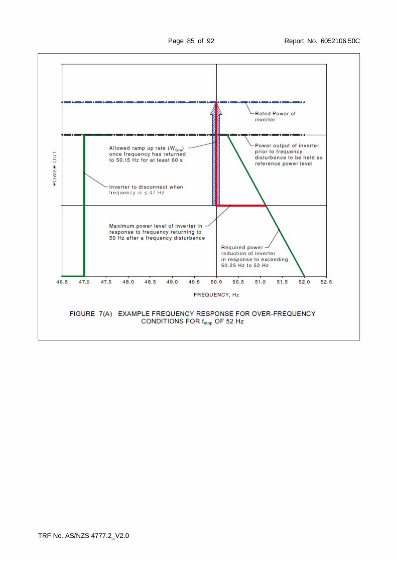
Page 85 of 92 Report No. 6052106.50C
TRF No. AS/NZS 4777.2_V2.0

Page 86 of 92 Report No. 6052106.50C
TRF No. AS/NZS 4777.2_V2.0
7.6 (Appendix I)
TABLE: Disconnection on external signal P
Model EA16KTSI
Demand response test Real current Reactive current Switching time Pass/Fail
DRM 0 at 100% 22.20 2.10 0.158 Pass
DRM 7 16.40 4.30 0.90 Pass
DRM 6 and DRM 7 10.20 4.30 0.70 Pass
DRM 6 11.80 2.60 0.35 Pass
DRM 5 and DRM 6 0.00 2.50 0.95 Pass
DRM 8 22.00 2.30 1.50 Pass
DRM 3 - - - -
DRM 3 and DRM 2 - - - -
DRM 2 - - - -
DRM 1 and DRM 2 - - - -
DRM 4 - - - -
Limit [s]: 2 s

Page 87 of 92 Report No. 6052106.50C
TRF No. AS/NZS 4777.2_V2.0
Test procedure:
I2.1 Test for demand response and disconnection on external signal:
(a) The inverter shall be connected into a test circuit equivalent to that shown in Figure G1. The voltage shall equal the grid test voltage.
(b) The inverter DRED connection (i.e. terminal block or RJ45 socket) shall be connected to a DRED though an auxiliary DRED test circuit, as shown in Figure II. The following applies: i. When measured from the inverter DRED connection point, and with less than 30 rnA (a.c. or
d.c.) current flow, each DRED switch (SI-SS) and auxiliary DRED test circuit switch (SO) shall have a voltage drop of less than 0.1 V when 'on'.
ii. When measured from the inverter DRED connection point, and with less than 30 rnA (a.c. or d.c.) current flow, the auxiliary DRED test circuit shall have a voltage drop of 1.5-1.6 V (a.c. or d.c.) between terminals REF GEN/0 and DRM1/5 and COM LOAD/0 and DRM1/5, when auxiliary switches S5a and S1a respectively are 'on'.
I2.2 Test for disconnection at rated current output: (a) Switch S9 (see Figure I1) shall be closed. (b) The input supply or inverter set-point shall be varied until the a.c. output of the inverter equals 100 ±5% of
its rated current output. (c) DRED switch SO (see Figure I1) shall be asserted and the time for the device under test to disconnect
shall be measured and recorded. (d) Where the inverter supports the provision of d.c. power to the DRED, power to the DRED shall remain after
the automatic disconnection device has operated. (e) The disconnect signal (S0) shall be removed and the inverter shall be allowed to automatically reconnect
(see Clause 7.6). (f) Switch S9 shall be opened and the time for the device under test to disconnect shall be measured and
recorded. See Clause 6.2.2(d). I2.3 Test for standard operation of generator demand response modes: (a) All DRM signals shall be removed and the input supply or inverter set-point shall be varied until the a.c.
output of the inverter equals 100 ±5% of its rated current output. The DRM 3 and DRM 7 reactive power lintits shall be set to their maximum allowed values (see Clause 6.2).
(b) DRED switch S7 shall be asserted and DRM 7 response assessed over a period of 2 min in accordance with Table I1.
(c) DRED switch S6 shall be asserted and simultaneous DRM 6 and DRM 7 response assessed over a period of 2 min in accordance with Table I1.
(d) DRED switch S7 shall be opened and DRM 6 response assessed over a period of 2 min in accordance with Table I1.
(e) DRED switch S5 shall be asserted and DRM 5 response assessed in accordance with Table I1. (f) All DRM signals shall be removed and the input supply or inverter set-point shall be varied until the a.c.
output of the inverter equals 50 ±5% of the inverter's rated current output and is in a state able to respond to DRM 8
(g) DRED switch S8 shall be opened and DRM 6 response assessed over a period of 2 min in accordance with Table I1.
I2.4 Test for standard operation of load demand response modes (such as for battery charging): (a) All DRM signals shall be removed and the input supply or inverter set-point shall be varied until the a.c.
draw of the inverter equals 100% of the inverter's rated current input. DRM 3 and DRM 7 reactive power lintits shall be set to their maximum allowed values (see Clause 6.2).
(b) DRED switch S3 shall be asserted and DRM 3 response assessed over a period of 2 min in accordance with Table I1.
(c) DRED switch S2 shall be asserted and simultaneous DRM 2 and DRM 3 response assessed over a period of 2 min in accordance with Table I1.
(d) DRED switch S3 shall be opened and DRM2 response assessed over a period of 2 min in accordance with Table I1.
(e) DRED switch Sl shall be asserted and DRM 1 response assessed over a period of 2 min in accordance with Table I1.
(f) All DRM signals shall be removed and the input supply or inverter set-point shall be varied until the a.c. draw of the inverter equals 50 ±5% of the inverter's rated current input and is in a state able to respond to DRM 4.
(g) DRED switch S4 shall be opened and DRM 4 response assessed over a period of 2 min in accordance

Page 88 of 92 Report No. 6052106.50C
TRF No. AS/NZS 4777.2_V2.0
with Table I1.
Supplementary information:
The automatic disconnection device shall incorporate the ability to disconnect on an external signal. If an external signal or demand response 'DRM 0' condition is asserted, the automatic disconnection device shall operate within 2 s. 6.3.5.3.3 Changes in a.c. operation and control When a demand response mode (except for DRM 0) is asserted or unasserted the power rate limit (WGra=16.67% of rated power per minute) shall apply to the increase or decrease in power generation or consumption and the transitions between power output levels.

Page 89 of 92 Report No. 6052106.50C
TRF No. AS/NZS 4777.2_V2.0
7.7 (Appendix G)
TABLE: Connection and reconnection procedure P
Model EA16KTSI
Connecting conditions for voltages:
G2.2 Reconnection description Reconnection time [s] Limit
(g) Reconnection after overvoltage 2 (V>>) 151.8 ≥ 60 s
(n) Reconnection after undervoltage (V<) 143.0 ≥ 60 s
(u) Reconnection after overvoltage 1 (V>) 148.0 ≥ 60 s
(v) Active power gradient after reconnection 390.0 16.67%
Reconnection after overvoltage 2 (V>>)
Active power gradient after reconnection
Connecting conditions for frequencies:
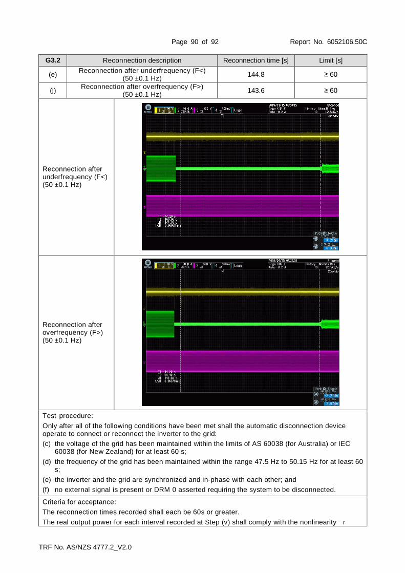
Page 90 of 92 Report No. 6052106.50C
TRF No. AS/NZS 4777.2_V2.0
G3.2 Reconnection description Reconnection time [s] Limit [s]
(e) Reconnection after underfrequency (F<)
(50 ±0.1 Hz) 144.8 ≥ 60
(j) Reconnection after overfrequency (F>)
(50 ±0.1 Hz) 143.6 ≥ 60
Reconnection after underfrequency (F<) (50 ±0.1 Hz)
Reconnection after overfrequency (F>) (50 ±0.1 Hz)
Test procedure:
Only after all of the following conditions have been met shall the automatic disconnection device operate to connect or reconnect the inverter to the grid:
(c) the voltage of the grid has been maintained within the limits of AS 60038 (for Australia) or IEC 60038 (for New Zealand) for at least 60 s;
(d) the frequency of the grid has been maintained within the range 47.5 Hz to 50.15 Hz for at least 60 s;
(e) the inverter and the grid are synchronized and in-phase with each other; and
(f) no external signal is present or DRM 0 asserted requiring the system to be disconnected.
Criteria for acceptance:
The reconnection times recorded shall each be 60s or greater.
The real output power for each interval recorded at Step (v) shall comply with the nonlinearity r

Page 91 of 92 Report No. 6052106.50C
TRF No. AS/NZS 4777.2_V2.0
equirements of Clause 6.3.5.4 and the default ramp rate of Clause 6.3.5.2.
(WGra default setting as 16.67%Pn per minute)

Page 92 of 92 Report No. 6052106.50C
TRF No. AS/NZS 4777.2_V2.0
7.8 TABLE: Security of protection settings P
The internal settings of the automatic disconnection device shall be secured against inadvertent or unauthorized tampering. Changes to the internal settings shall require the use of a tool and special instructions not provided to unauthorized personnel.
NOTE: Special interface devices and passwords are regarded as tools. The installer-accessible settings of the automatic disconnection device shall be capable of being adjusted within the limits specified in Clause 7.5. The manufacturer settings of the automatic disconnection device, specified in Clause 7.4, shall be secured against changes. NOTE: It is acceptable for the manufacturer settings to be part of a country-specific set-up, selected at installation.
Compliance shall be determined by inspection.
--- End of test report---