TEST PIT LOGGING RESULTS - nrc.gov · MACTEC Engineering and Consulting MACTEC Project 6468-06-1299...
18
MACTEC Engineering and Consulting MACTEC Project 6468-06-1299 Bellefonte Nuclear Station COL Geotechnical Data Report Attachment B, Rev. 1 April 2007 TEST PIT LOGGING RESULTS 1.0 INTRODUCTION The purpose of the excavation and logging of exploratory test pits was to characterize the subsurface conditions of soil and bedrock at designated locations to support the COL for the two new AP1000 units. The use of test pit excavations as an exploratory tool was proposed in the Geotechnical Data Collection Plan, Rev.0. Quality Assurance (QA) aspects of the field work were governed by the MACTEC QAPD, Rev 0, dated April 14, 2006. 2.0 SCOPE OF WORK Each test pit location was selected to address specific geologic conditions. These conditions included confirmation of weathering patterns of the underlying bedrock, the presence and configuration of fill, the presence of faults and to obtain bulk soil and rock samples for classification and potential laboratory testing. The preparation of test pit logs, sample collection and photographs represents a record of field observations made by the geologist responsible for the work. Originally 16 test pits were proposed; this number was later modified based on the results of drilling and geologic mapping. During Late July and early August of 2006 nine test pits were excavated and logged by geologists from William Lettis & Associates (WLA). Logging geologists included William Godwin, Jeff Hoeft and Janet Sowers. On March 26 to 27, an additional test pit was excavated and logged by Janet Sowers and Greg Van Etten of WLA. 3.0 METHODOLOGY The procedure for excavating, shoring, and backfilling of the test pits was set forth in Work Instruction No. 19 (WI-19), approved July 20, 2007. Health and Safety procedures as outlined in TVA Procedure Number 804 and 711 were followed. Prior to the work a job hazard analysis was prepared and approved by TVA, and the operator and logging geologists attended an onsite safety briefing led by TVA and Enercon personnel to establish reporting protocols and communication channels. The test pits were excavated using equipment and operators provided under subcontract by Andrews Dirt and Gravel of Hollywood, Alabama. The subcontractor’s equipment included a rubber-tire Case 580M backhoe and a track-mounted John Deere 120C excavator. 4.0 QUALITY ASSURANCE The logging of the test pit followed procedures and specifications included in WI-19. Descriptions of soil and rock followed ASTM D2487 and D2488. Test pit logs, safety forms and daily reports were prepared daily. Photos and photo logs were also submitted to the MACTEC site coordinator for inclusion in the QA files. 5.0 RESULTS DCN BN 394
Transcript of TEST PIT LOGGING RESULTS - nrc.gov · MACTEC Engineering and Consulting MACTEC Project 6468-06-1299...

MACTEC Engineering and Consulting MACTEC Project 6468-06-1299Bellefonte Nuclear Station COL Geotechnical Data Report Attachment B, Rev. 1 April 2007
TEST PIT LOGGING RESULTS
1.0 INTRODUCTION
The purpose of the excavation and logging of exploratory test pits was to characterize the subsurface conditions of soil and bedrock at designated locations to support the COL for the two new AP1000 units. The use of test pit excavations as an exploratory tool was proposed in the Geotechnical Data Collection Plan, Rev.0. Quality Assurance (QA) aspects of the field work were governed by the MACTEC QAPD, Rev 0, dated April 14, 2006.
2.0 SCOPE OF WORK
Each test pit location was selected to address specific geologic conditions. These conditions included confirmation of weathering patterns of the underlying bedrock, the presence and configuration of fill, the presence of faults and to obtain bulk soil and rock samples forclassification and potential laboratory testing.
The preparation of test pit logs, sample collection and photographs represents a record of field observations made by the geologist responsible for the work. Originally 16 test pits wereproposed; this number was later modified based on the results of drilling and geologic mapping.During Late July and early August of 2006 nine test pits were excavated and logged by geologists from William Lettis & Associates (WLA). Logging geologists included WilliamGodwin, Jeff Hoeft and Janet Sowers. On March 26 to 27, an additional test pit was excavated and logged by Janet Sowers and Greg Van Etten of WLA.
3.0 METHODOLOGY
The procedure for excavating, shoring, and backfilling of the test pits was set forth in Work Instruction No. 19 (WI-19), approved July 20, 2007. Health and Safety procedures as outlined in TVA Procedure Number 804 and 711 were followed. Prior to the work a job hazard analysis was prepared and approved by TVA, and the operator and logging geologists attended an onsite safety briefing led by TVA and Enercon personnel to establish reporting protocols and communication channels. The test pits were excavated using equipment and operators provided under subcontract by Andrews Dirt and Gravel of Hollywood, Alabama. The subcontractor’s equipment included a rubber-tire Case 580M backhoe and a track-mounted John Deere 120C excavator.
4.0 QUALITY ASSURANCE
The logging of the test pit followed procedures and specifications included in WI-19.Descriptions of soil and rock followed ASTM D2487 and D2488. Test pit logs, safety forms and daily reports were prepared daily. Photos and photo logs were also submitted to the MACTECsite coordinator for inclusion in the QA files.
5.0 RESULTS
DCN BN 394
MACTEC Engineering and Consulting MACTEC Project 6468-06-1299Bellefonte Nuclear Station COL Geotechnical Data Report Attachment B, Rev. 1 April 2007
The following is a description of the purpose, location and observation of each of the nine test pits. The logs of each test pit are provided as Figures 1 through 9 of this data report.
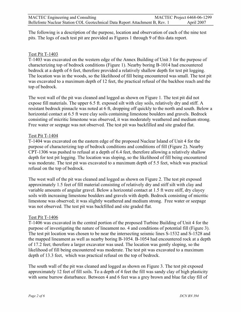
Test Pit T-1403T-1403 was excavated on the western edge of the Annex Building of Unit 3 for the purpose of characterizing top of bedrock conditions (Figure 1). Nearby boring B-1014 had encountered bedrock at a depth of 6 feet, therefore provided a relatively shallow depth for test pit logging. The location was in the woods, so the likelihood of fill being encountered was small. The test pitwas excavated to a maximum depth of 12 feet, the practical refusal of the backhoe reach and the top of bedrock.
The west wall of the pit was cleaned and logged as shown on Figure 1. The test pit did not expose fill materials. The upper 6.5 ft. exposed silt with clay soils, relatively dry and stiff. A resistant bedrock pinnacle was noted at 6 ft, dropping off quickly to the north and south. Below a horizontal contact at 6.5 ft were clay soils containing limestone boulders and gravels. Bedrock consisting of micritic limestone was observed, it was moderately weathered and medium strong.Free water or seepage was not observed. The test pit was backfilled and site graded flat.
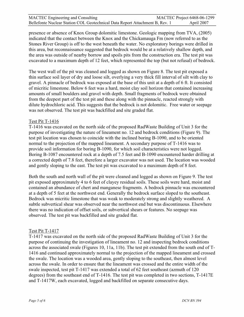
Test Pit T-1404T-1404 was excavated on the eastern edge of the proposed Nuclear Island of Unit 4 for the purpose of characterizing top of bedrock conditions and conditions of fill (Figure 2). Nearby CPT-1306 was pushed to refusal at a depth of 6.4 feet, therefore allowing a relatively shallow depth for test pit logging. The location was sloping, so the likelihood of fill being encountered was moderate. The test pit was excavated to a maximum depth of 5.5 feet, which was practical refusal on the top of bedrock.
The west wall of the pit was cleaned and logged as shown on Figure 2. The test pit exposed approximately 1.5 feet of fill material consisting of relatively dry and stiff silt with clay and variable amounts of angular gravel. Below a horizontal contact at 1.5 ft were stiff, dry clayey soils with increasing limestone boulders and gravels with depth. Bedrock consisting of micriticlimestone was observed; it was slightly weathered and medium strong. Free water or seepage was not observed. The test pit was backfilled and site graded flat.
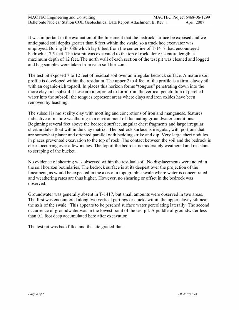
Test Pit T-1406T-1406 was excavated in the central portion of the proposed Turbine Building of Unit 4 for the purpose of investigating the nature of lineament no. 4 and conditions of potential fill (Figure 3). The test pit location was chosen to be near the intersecting seismic lines S-1532 and S-1528 and the mapped lineament as well as nearby boring B-1054. B-1054 had encountered rock at a depth of 17.2 feet; therefore a larger excavator was used. The location was gently sloping, so the likelihood of fill being encountered was moderate. The test pit was excavated to a maximumdepth of 13.3 feet, which was practical refusal on the top of bedrock.
The south wall of the pit was cleaned and logged as shown on Figure 3. The test pit exposed approximately 12 feet of fill soils. To a depth of 4 feet the fill was sandy clay of high plasticity with some burrow disturbance. Between 4 and 6 feet was a grey brown and blue fat clay fill of
Page 2 of 6 DCN BN 394

MACTEC Engineering and Consulting MACTEC Project 6468-06-1299Bellefonte Nuclear Station COL Geotechnical Data Report Attachment B, Rev. 1 April 2007
medium stiffness. Below 6 ft the clay was less plastic, moist to wet and stiff, representing a different type of fill than above. There were no observed subvertical shears, or offset soils indicative of faulting. Bedrock consisting of deeply weathered, friable micritic limestone was observed below 12 feet, becoming less weathered and hard at a refusal depth of 13.3 feet. From12 to 13 feet the eastern end of the pit exposed clean gravel (identified by long-time TVA personnel as “78” type bedding material). It was loose and had a tendency to fall into the unsupported excavation. The presence of this material at such a great depth and adjacent to intact limestone bedrock suggests that there is a subdrain or other utility pipe nearby. Although TVA personnel do not have drawings that support the presences of an active utility, historic photos show a preexisting swale in this area that may have had a subdrain placed in a V-slot, covered with gravel and backfilled just to the east. Minor seepage was observed. The test pit was backfilled and site graded flat.
Test Pit T-1409T-1409 was excavated opposite the proposed Administration building south of Unit 4 for the purpose of characterizing top of bedrock conditions and conditions of fill (Figure 4). A boring (H-46) reported in the FSAR (1986) had encountered solution features at an elevation of 614 to 616 feet. It was hoped that these features could be observed in the test pit excavation. The test pit was excavated to a maximum depth of 12 feet, or elevation 615 feet) and did not encounter bedrock at all.
The northeast wall of the pit was cleaned and logged as shown on Figure 4. The test pit exposed approximately 4 feet of fill material consisting of thin lifts of alternating clay and gravel thatwere dry to moist and stiff silt with dense. Below 4 ft. were thick, near horizontal soil layers ofmottled, very stiff clay. Numerous pressure faces were observed with increasing boulder and gravel contents with depth. Below a horizontal contact at 6.5 ft were stiff, dry clayey soils with increasing limestone boulders and gravels with depth. Free water or seepage was not observed.The test pit was backfilled and site graded flat.
Test Pit T-1410T-1410 was excavated to the east of Unit 4 for the purpose of characterizing top of bedrock conditions. The test pit area corresponds to a northerly project of the the Eastern Anomaly (EA) zone, reported in TVA, (2005). By comparing the subsurface conditions in this vicinity with those further to the west a qualitative assessment could be made of the likelihood of deeper weathering and more karstic conditions that were characteristic of the EA zone (Figure 5). Nearby boring B-1061 had encountered bedrock at a depth of 7.6 feet, ideal for a relatively shallow test pit depth. The location was also adjacent to seismic line S-1529, so there was a good opportunity to correlate this area with test pit, borings and refraction surveys. The test pit was excavated to a maximum depth of 9 feet, at at which point the backhoe could not excavate further into the resistant bedrock t
The northwest wall of the pit was cleaned and logged as shown on Figure 5. The test pit exposed soils we interpreted to be fill materials to a depth of 1.5ft. These soils were dry, hard and had abundant roots. The test pit was adjacent to a gravel road. Below 1.5 feet were subhorizontal soil layers of clayey silt to clay that were moist, friable and contain distinctive manganese nodulesand coatings. A resistant bedrock pinnacle was noted at 7 ft, dropping off quickly to the northeast
Page 3 of 6 DCN BN 394

MACTEC Engineering and Consulting MACTEC Project 6468-06-1299Bellefonte Nuclear Station COL Geotechnical Data Report Attachment B, Rev. 1 April 2007
and south. Bedrock consisted of micritic limestone that was irregularly weathered with solution features and a weathered rind on some calcareous shale or siltstone beds. Whereas the exploration methods of Eastern Anomaly zone in the TVA study did not include open excavations, the features observed in this test pit did not seem that much different than those observed elsewhere. We can not conclude solely on test pit excavations alone whether a zone of greater karst development similar to the EA zone is in this vicinity. water or seepage was not observed. The test pit was backfilled and site graded flat.
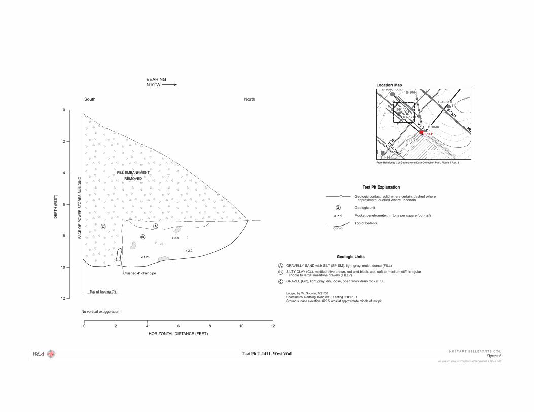
Test Pit T-1411T-1411 was excavated at the southeastern corner of the proposed Turbine Building of Unit 4 (Figure 6). The purpose was to remove a section of a perimeter fill berm from the Power Storesbuilding to allow access by a drill rig to drill boring B-1038, and to confirm the dimensions of the spread footing. In addition there was a history of mold in the building caused potentially by a high groundwater condition. The test pit was excavated to a maximum depth of 10 feet from the top of the berm and 3 feet from adjacent grade as shown on Figure 6.
The west wall of the pit was cleaned and logged as shown on Figure 6. The test pit exposed an irregularly shaped wedge of gravel fill that rested against the wall of the Power Stores building.The gravel fill contained a thin-wall plastic drain pipe that was crushed and inoperable. The footing for the building was not exposed, but drawings indicated that it was approximately 3 feet from the wall face. Adjacent to the crushed pipe was a silty clay fill, wet and soft to mediumstiff. Free water or seepage was not observed, although the area was wet. The test pit wasbackfilled to adjacent grade, but the berm was not replaced.
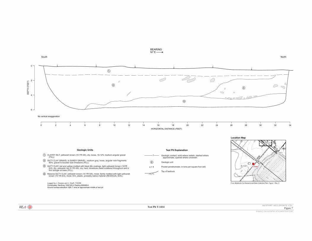
Test Pit T-1414T-1414 was excavated opposite the Power Stores building south of proposed Unit 4 for the purpose of characterizing fill and top of bedrock conditions, and to investigate a surface feature seen in historic photos (Figure 7). A 1980 site topographic map and an aerial photo dated 1979 depicted a pit or excavation in this area during construction. It was unclear whether this feature was artificial (i.e. drainage sump) or a result of collapse. Test pit T-1414 was positioned to extend from just outside the boundary of the feature to the middle or deepest portion. It also was near boring B-1081 and seismic line S-1525. Boring B-1081, to the northwest had encountered bedrock at a depth of 11.5 feet. The test pit was excavated to a maximum depth of 6 feet.
The west wall of the pit was cleaned and logged as shown on Figure 7. The test pit exposed a 1-foot-thick horizontal fill layer of dry and loose silt, overlying a thick fill interval of silty clay to clayey gravel. The gravelly wedge of fill was exposed at the northern end of the test pit, and transitioned into the clayey gravel subunit to the south. Beneath the fill layer at a depth an approximately 4.5 feet was a massive, residual soil. The flat lying nature of this unit and the factthat the test pit extended to near the center of the surface feature, precluded the presence of subsurface collapse. Bedrock was not encountered. Free water or seepage was not observed. The test pit was backfilled and site graded flat.
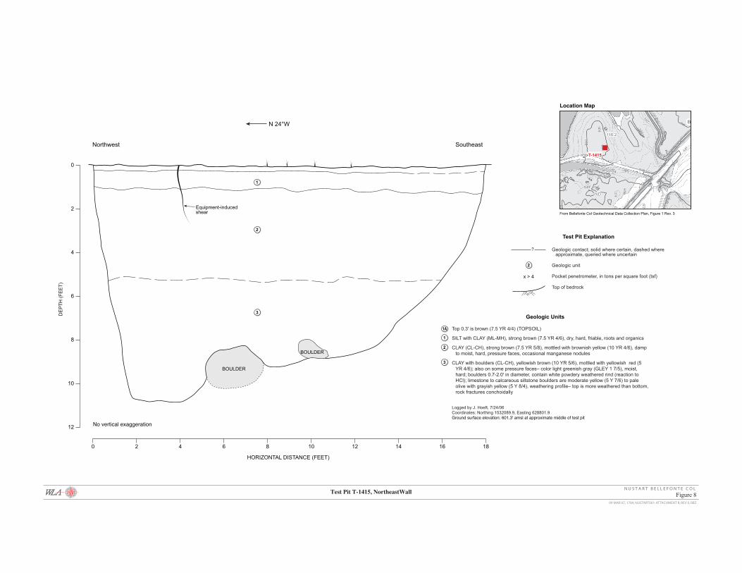
Test Pit T-1415T-1415 was excavated on a wooded parcel of land 1300 feet west of proposed Unit 4 on a smallpeninsula beside the Town Creek Embayment (Figure 8). Its purpose was to determine the
Page 4 of 6 DCN BN 394
MACTEC Engineering and Consulting MACTEC Project 6468-06-1299Bellefonte Nuclear Station COL Geotechnical Data Report Attachment B, Rev. 1 April 2007
presence or absence of Knox Group dolomitic limestone. Geologic mapping from TVA, (2005) indicated that the contact between the Knox and the Chickamauga Fm (now referred to as the Stones River Group) is off to the west beneath the water. No exploratory borings were drilled in this area, but reconnaissance suggested that bedrock would be at a relatively shallow depth, and the area was outside of nearby borrow and spoils pits from the construction era. The test pit was excavated to a maximum depth of 12 feet, which represented the top (but not refusal) of bedrock.
The west wall of the pit was cleaned and logged as shown on Figure 8. The test pit exposed a thin surface soil layer of dry and loose silt, overlying a very thick fill interval of silt with clay to gravel. A pinnacle of bedrock was exposed at the base of this unit at a depth of 6 ft. It consisted of micritic limestone. Below 6 feet was a hard, moist clay soil horizon that contained increasingamounts of small boulders and gravel with depth. Small fragments of bedrock were obtained from the deepest part of the test pit and these along with the pinnacle, reacted strongly with dilute hydrochloric acid. This suggests that the bedrock is not dolomitic. Free water or seepagewas not observed. The test pit was backfilled and site graded flat.
Test Pit T-1416T-1416 was excavated on the north side of the proposed RadWaste Building of Unit 3 for the purpose of investigating the nature of lineament no. 12 and bedrock conditions (Figure 9). The test pit location was chosen to coincide with the inclined boring B-1090, and to be oriented normal to the projection of the mapped lineament. A secondary purpose of T-1416 was to provide soil information for boring B-1090, for which soil characteristics were not logged. Boring B-1087 encountered rock at a depth of 7.5 feet and B-1090 encountered harder drilling at a corrected depth of 7.8 feet, therefore a larger excavator was not used. The location was wooded and gently sloping to the east. The test pit was excavated to a maximum depth of 8 feet.
Both the south and north wall of the pit were cleaned and logged as shown on Figure 9. The test pit exposed approximately 4 to 6 feet of clayey residual soils. These soils were hard, moist and contained an abundance of chert and manganese fragments. A bedrock pinnacle was encountered at a depth of 5 feet at the northwest end. Generally the bedrock surface sloped to the southeast.Bedrock was micritic limestone that was weak to moderately strong and slightly weathered. A subtle subvertical shear was observed near the northwest end but was discontinuous. Elsewhere there was no indication of offset soils, or subvertical shears or features. No seepage wasobserved. The test pit was backfilled and site graded flat.
Test Pit T-1417T-1417 was excavated on the north side of the proposed RadWaste Building of Unit 3 for the purpose of continuing the investigation of lineament no. 12 and inspecting bedrock conditions across the associated swale (Figures 10, 11a, 11b). The test pit extended from the south end of T-1416 and continued approximately normal to the projection of the mapped lineament and crossed the swale. The location was a wooded area, gently sloping to the southeast, then almost level across the swale. In order to ensure that the lineament was crossed and the entire width of the swale inspected, test pit T-1417 was extended a total of 62 feet southeast (azmuth of 120degrees) from the southeast end of T-1416. The test pit was completed in two sections, T-1417E and T-1417W, each excavated, logged and backfilled on separate consecutive days.
Page 5 of 6 DCN BN 394
MACTEC Engineering and Consulting MACTEC Project 6468-06-1299Bellefonte Nuclear Station COL Geotechnical Data Report Attachment B, Rev. 1 April 2007
It was important in the evaluation of the lineament that the bedrock surface be exposed and we anticipated soil depths greater than 8 feet within the swale, so a track hoe excavator was employed. Boring B-1086 which lay 6 feet from the centerline of T-1417, had encountered bedrock at 7.5 feet. The test pit was excavated to the top of rock along its entire length, a maximum depth of 12 feet. The north wall of each section of the test pit was cleaned and logged and bag samples were taken from each soil horizon.
The test pit exposed 7 to 12 feet of residual soil over an irregular bedrock surface. A mature soil profile is developed within the residuum. The upper 2 to 4 feet of the profile is a firm, clayey silt with an organic-rich topsoil. In places this horizon forms “tongues” penetrating down into the more clay-rich subsoil. These are interpreted to form from the vertical penetration of perched water into the subsoil; the tongues represent areas where clays and iron oxides have been removed by leaching.
The subsoil is moist silty clay with mottling and concretions of iron and manganese, features indicative of mature weathering in a environment of fluctuating groundwater conditions. Beginning several feet above the bedrock surface, angular chert fragments and large irregular chert nodules float within the clay matrix. The bedrock surface is irregular, with portions that are somewhat planar and oriented parallel with bedding strike and dip. Very large chert nodules in places prevented excavation to the top of rock. The contact between the soil and the bedrock is clear, occurring over a few inches. The top of the bedrock is moderately weathered and resistant to scraping of the bucket.
No evidence of shearing was observed within the residual soil. No displacements were noted in the soil horizon boundaries. The bedrock surface is at its deepest over the projection of the lineament, as would be expected in the axis of a topographic swale where water is concentrated and weathering rates are thus higher. However, no shearing or offset in the bedrock wasobserved.
Groundwater was generally absent in T-1417, but small amounts were observed in two areas.The first was encountered along two vertical partings or cracks within the upper clayey silt nearthe axis of the swale. This appears to be perched surface water percolating laterally. The second occurrence of groundwater was in the lowest point of the test pit. A puddle of groundwater less than 0.1 foot deep accumulated here after excavation.
The test pit was backfilled and the site graded flat.
Page 6 of 6 DCN BN 394

0
2
4
6
8
10
12
DE
PT
H (
FE
ET
)
HORIZONTAL DISTANCE (FEET)
0 2 4 6 8 10 12 14 16 18
1
2
3
4
3
1A
South
x > 4
x > 4
BEARING
North
No vertical exaggeration
North
Test Pit Explanation
2
Geologic contact; solid where certain, dashed where approximate, queried where uncertain
Geologic unit
Pocket penetrometer, in tons per square foot (tsf)
Top of bedrock
?
x > 4
Geologic Units
1
2
4
3
Dark brown (10 YR 3/3), roots and organic matter (TOPSOIL)
SILT with CLAY (ML-MH), yellowish brown (10 YR 5/6), dry, very stiff (friable)
SILT with CLAY (ML-MH), yellowish brown (10 YR 5/6), dry to moist at bottom, has prevalent manganese nodules, near base becoming mottled with yellowish red (5 YR 4/6), occasional roots
CLAY (CL-CH), yellowish brown (10 YR 5/6), moist, hard, occasional manganese nodules, pressure faces, occasional limestone boulders and large gravel, limestone clasts have white weathered rind, boulders up to 2' in diameter
Micritic LIMESTONE, medium grey (N5), slightly weathered, medium strong, strong HCl reaction (BEDROCK)
Logged by J. Hoeft, 7/22/06Coordinates: Northing 1533027.2, Easting 628350.6Ground surface elevation: 610.2' amsl at approximate middle of test pit
1A
Location Map
T-1403
From Bellefonte Col Geotechnical Data Collection Plan, Figure 1 Rev. 3
09 MAR 07, 1784, NUSTART001-ATTACHMENT B, REV 0, RBZ
Test Pit T-1403, West Wall Figure 1N U S T A R T B E L L E F O N T E C O L

0
2
4
6
DE
PT
H (
FE
ET
)
HORIZONTAL DISTANCE (FEET)
0 2 4 6 8 10 12
1A
East
BEARING
West
SMEAR
N6°E
No vertical exaggeration
Upper zone
SILT with CLAY (ML-MH), brownish yellow (10YR 6/6 dry), dry, hard, angular gravel and organics, gravel is 0.02-0.2' in diameter; also areas of CLAY (CL-CH), reddish brown (2.5YR 4/4), dry, hard, gravel is limestone (FILL/TOPSOIL)
CLAY with SILT (CL-CH), light olive brown (2.5 YR 5/6), dry, hard, contains manganese modules (0.01-0.03')
CLAY (CL-CH), yellowish brown (10YR 5/6), moist, very stiff, gravel and cobble sized limestone (mostly along the contact of , angular white weathering rind
Micritic LIMESTONE, medium gray (N5), micrite, slightly weathered, medium strong
Logged by J. Hoeft, 7/22/06Coordinates: Northing 1532443.4, Easting 629154.6Ground surface elevation: 618.4' amsl at approximate middle of test pit
Geologic Units
5/6) ,4
1
1
2
2 2
3
3
3
4
4
Test Pit Explanation
2
Geologic contact; solid where certain, dashed where approximate, queried where uncertain
Geologic unit
Pocket penetrometer, in tons per square foot (tsf)
Top of bedrock
?
x > 4
1A
Location Map
T-1404
From Bellefonte Col Geotechnical Data Collection Plan, Figure 1 Rev. 3
09 MAR 07, 1784, NUSTART001-ATTACHMENT B, REV 0, RBZ
Test Pit T-1404, West Wall Figure 2N U S T A R T B E L L E F O N T E C O L

HORIZONTAL DISTANCE (FEET)
0 2 4 6 8 10 12 14 16 18 20 22 24
0
2
4
6
8
10
12
14
DE
PT
H (
FE
ET
)
1A
1
2
3
6
4
5
5A
KK K
TD 13.3'
Limit of test pit entry
x > 4.5 pppp x > 4.5
pp x 3.5 x > 4.5 pp
Possibleburiedpipe?
Limestonefragment
? ? ??
Geologic Units
1A
1
2
3
6
4
5
5A
SANDY CLAY (SC-CL), medium brown to white, dry, loose, contains abundant rootlets, organics and trace concrete fragments (FILL)
SANDY CLAY (CL), medium to mottled red-brown and yellow (10 YR 4/6), moist, medium stiff, contains Krotovina bores (K), coarse sand to gravel, clasts of limestone gradual below 2.5' to yellow-brown with black SAND
FAT CLAY (CH-CC), reddish brown (2.5 YR 4/4), moist, medium stiff (FILL)
CLAY (CL), gray brown and blue (Gley 2 5/1), moist, medium stiff organic-rich, odoriferous (FILL)
CLAY (CL), yellow brown (10 YR 5/1) moist to wet, stiff, includes medium sand, chert fragments, mature (FILL)
Micritic LIMESTONE, yellowish red brown with black (5 Y 7/6), deeply weathered, friable, black oxide surfaces, wet (BEDROCK)
Micritic LIMESTONE, buff white to light gray (6 N 6), hard, shiny, closely fractured, contains soft soil infill of small 3-6" vvgs (test pit refusal)
Coarse SAND with GRAVEL (SP), gray (10 YR 5/1), loose, wet, possible pipe bedding (“78”) material (FILL)
Logged by W. Godwin, 8/1/06Coordinates: Northing 1532248.2, Easting 628801.2Ground surface elevation: 628.0' amsl at approximate middle of test pit
East West
No vertical exaggeration
Location Map
N 75°E BEARING
T-1406
From Bellefonte Col Geotechnical Data Collection Plan, Figure 1 Rev. 3
Test Pit Explanation
2
Geologic contact; solid where certain, dashed where approximate, queried where uncertain
Geologic unit
Pocket penetrometer, in tons per square foot (tsf)
Top of bedrock
?
x > 4
09 MAR 07, 1784, NUSTART001-ATTACHMENT B, REV 0, RBZ
Test Pit T-1406, South Wall Figure 3N U S T A R T B E L L E F O N T E C O L

0
2
4
6
8
10
12
DE
PT
H (
FE
ET
)
HORIZONTAL DISTANCE (FEET)
0 2 4 6 8 10 12 14
1
2
3
4
5
6
7
1A
BOULDERIMPRINT
x > 4
x > 3.5
x > 3.5
x > 2.5
x > 2.5
Northwest
BEARING
Southeast
No vertical exaggeration
N 45°W
Geologic Units
1
2
3
Upper 0.3' are dark brown (10 YR 3/3)
SILT with CLAY (ML-MH) yellowish brown (10 YR 5/4 dry), dry, hard, organics throughout
(Several lifts) GRAVEL with CLAY and SILT, light yellowish brown (10 YR 6/4), dry, hard/very dense, limestone angular gravel (<0.1' diameter) ~ 95% gravel (FILL)
CLAY with GRAVEL, red (2.5 YR 4/6), damp, hard, gravel is 0.02' diameter to fist sized, ~15% gravel (FILL)
GRAVEL with CLAY and SILT, pale yellow (2.5 Y 7/4), dry, hard/dense, ~95% gravel, gravel is angular limestone (<0.15' diameter) (FILL)
CLAY (CL-CH), dark yellowish brown (10 YR 4/4), moist, very stiff, medium plastic, pressure faces
CLAY with SILT (CL-CH), yellowish brown (10 YR 5/6), mottled with yellowish red (5 YR 4/6), moist, very stiff, occasional gravel-size limestone clasts, angular
CLAY (CL-CH), yellowish brown (10 YR 5/6), moist, very stiff, medium plastic pressure faces, some pressure faces are light gray (2.5 Y 7/1); below 9' change to CLAY with GRAVEL and BOULDERS (CL-CH), yellowish brown (10 YR 5/6), moist, very stiff, gravel and boulders are micritic limestone, medium gray (N5), with weathering rind of a white color, boulders are 1-2.5' in diameter
Logged by Jeff Hoeft, 7/23/06Coordinates: Northing 1532050.2, Easting 628451.3Ground surface elevation: 627.5' amsl at approximate middle of test pit
4
5
6
7
Location Map
T-1409
From Bellefonte Col Geotechnical Data Collection Plan, Figure 1 Rev. 3
1A
Test Pit Explanation
2
Geologic contact; solid where certain, dashed where approximate, queried where uncertain
Geologic unit
Pocket penetrometer, in tons per square foot (tsf)
Top of bedrock
?
x > 4
09 MAR 07, 1784, NUSTART001-ATTACHMENT B, REV 0, RBZ
Test Pit T-1409, Northeast Wall Figure 4N U S T A R T B E L L E F O N T E C O L

0
2
4
6
8
10
12
DE
PT
H (
FE
ET
)
HORIZONTAL DISTANCE (FEET)
0 2 4 6 8 10 12
1
2
4
5
6
7
3
Pole
BEARING
Geologic Units
1
2
4
5
6
7
3
GRAVELLY FILL, abundant roots (FILL)
CLAYEY SILT with rock fragments, pale yellow (2.5 YR 7/3), dry, hard, manganese coatings, few roots (FILL?)
CLAYEY SILT, dark yellow-brown (10 YR 4/4), hard, manganese coatings, some laminae of brown-yellow clay
SILTY CLAY, brown-yellow (10 YR 6/6), moist, friable, with black Fe/Mn, pressure faces, pea-sized iron concretions, locally sandy
SILTY CLAY (CL-CH), yellow-brown (10 YR 5/8), mottled with red (2.5 YR 4/8), moist, friable
SILTY CLAY (CR-CL), yellow-brown (10 YR 5/6), moist, friable, pressure faces, manganese coatings
WEATHERED ROCK, limestone blocks are solutioned into irregular shapes; calcareous siltstone has soft weathering rind
Logged by W. Godwin, J. Sowers and J. Hoeft, 7/21/06Coordinates: Northing 1532120.9, Easting 629096.8Ground surface elevation: 630.6' amsl at approximate middle of test pit
Southwest Northeast
No vertical exaggeration
N 24°E
Test Pit Explanation
2
Geologic contact; solid where certain, dashed where approximate, queried where uncertain
Geologic unit
Pocket penetrometer, in tons per square foot (tsf)
Top of bedrock
?
x > 4
Location Map
T-1410
From Bellefonte Col Geotechnical Data Collection Plan, Figure 1 Rev. 3
09 MAR 07, 1784, NUSTART001-ATTACHMENT B, REV 0, RBZ
Test Pit T-1410, Northwest Wall Figure 5N U S T A R T B E L L E F O N T E C O L
0
2
4
6
8
10
12
DE
PT
H (
FE
ET
)
HORIZONTAL DISTANCE (FEET)
0 2 4 6 8 10 12
AC
B
FILL EMBANKMENT
REMOVED
Crushed 4" drainpipe
FAC
E O
F P
OW
ER
ST
OR
ES
BU
ILD
ING
x 1.25
x 2.5
x 2.0
Top of footing (?)
South
BEARING
North
N10°W
Geologic Units
A
B
C
GRAVELLY SAND with SILT (SP-SM), light gray, moist, dense (FILL)
SILTY CLAY (CL), mottled olive brown, red and black, wet, soft to medium stiff, irregular cobble to large limestone gravels (FILL?)
GRAVEL (GP), light gray, dry, loose, open work drain rock (FILL)
Logged by W. Godwin, 7/21/06Coordinates: Northing 1532089.9, Easting 628801.9Ground surface elevation: 629.5' amsl at approximate middle of test pit
No vertical exaggeration
Test Pit Explanation
2
Geologic contact; solid where certain, dashed where approximate, queried where uncertain
Geologic unit
Pocket penetrometer, in tons per square foot (tsf)
Top of bedrock
?
x > 4
Location Map
T-1411
From Bellefonte Col Geotechnical Data Collection Plan, Figure 1 Rev. 3
09 MAR 07, 1784, NUSTART001-ATTACHMENT B, REV 0, RBZ
Test Pit T-1411, West Wall Figure 6N U S T A R T B E L L E F O N T E C O L
HORIZONTAL DISTANCE (FEET)
0 2 4 6 8 10 12 14 16 18 20 22 24 26 28 30 32 34
0
2
4
6
DE
PT
H (
FE
ET
)
BEARING
1
2
3
4
South North
N1°E
Geologic Units
1
2
3
4
CLAYEY SILT, yellowish brown (10 YR 5/6), dry, loose, 10-12% medium angular gravel (FILL)
SILTY CLAY GRAVEL to SANDY GRAVEL, medium gray, loose, angular rock fragments 80%, gravel to boulder size limestone (FILL)
SILTY CLAY, red and yellow mottled with black Mn coatings, light yellowish brown (10YR 6/4), dry, yellowish red (5 YR 4/6), dry, hard, limestone clasts scattered throughout and in thin stringer at base (FILL)
Massive SILTY CLAY, yellowish brown (10 YR 5/6), moist, faintly mottled with light yellowish brown (10 YR 6/4), moist, firm, plastic, probably native material (RESIDUAL SOIL)
Logged by J. Sowers and J. Hoeft, 7/22/06Coordinates: Northing 1532120.9, Easting 629096.8Ground surface elevation: 626.7' amsl at approximate middle of test pit
No vertical exaggeration
Test Pit Explanation
2
Geologic contact; solid where certain, dashed where approximate, queried where uncertain
Geologic unit
Pocket penetrometer, in tons per square foot (tsf)
Top of bedrock
?
x > 4
Location Map
T-1414
From Bellefonte Col Geotechnical Data Collection Plan, Figure 1 Rev. 3
09 MAR 07, 1784, NUSTART001-ATTACHMENT B, REV 0, RBZ
Test Pit T-1414 Figure 7N U S T A R T B E L L E F O N T E C O L
0
2
4
6
8
10
12
DE
PT
H (
FE
ET
)
HORIZONTAL DISTANCE (FEET)
0 2 4 6 8 10 12 14 16 18
1
2
3
Equipment-inducedshear
BOULDER
BOULDER
Geologic Units
1
2
3
Top 0.3' is brown (7.5 YR 4/4) (TOPSOIL)
SILT with CLAY (ML-MH), strong brown (7.5 YR 4/6), dry, hard, friable, roots and organics
CLAY (CL-CH), strong brown (7.5 YR 5/8), mottled with brownish yellow (10 YR 4/6), damp to moist, hard, pressure faces, occasional manganese nodules
CLAY with boulders (CL-CH), yellowish brown (10 YR 5/6), mottled with yellowish red (5 YR 4/6); also on some pressure faces– color light greenish gray (GLEY 1 7/5), moist, hard; boulders 0.7-2.0' in diameter, contain white powdery weathered rind (reaction to HCl); limestone to calcareous siltstone boulders are moderate yellow (5 Y 7/6) to pale olive with grayish yellow (5 Y 8/4), weathering profile– top is more weathered than bottom, rock fractures conchoidally
Logged by J. Hoeft, 7/24/06Coordinates: Northing 1532089.9, Easting 628801.9Ground surface elevation: 601.3' amsl at approximate middle of test pit
Northwest Southeast
No vertical exaggeration
N 24°W
1A
Test Pit Explanation
2
Geologic contact; solid where certain, dashed where approximate, queried where uncertain
Geologic unit
Pocket penetrometer, in tons per square foot (tsf)
Top of bedrock
?
x > 4
Location Map
T-1415
From Bellefonte Col Geotechnical Data Collection Plan, Figure 1 Rev. 3
09 MAR 07, 1784, NUSTART001-ATTACHMENT B, REV 0, RBZ
Test Pit T-1415, NortheastWall Figure 8N U S T A R T B E L L E F O N T E C O L

0
2
4
6
8
DE
PT
H (
FE
ET
)
HORIZONTAL DISTANCE (FEET)
0 2 4 6 8 10 12 14 16 18 20 22 24 26 28
SOUTHWALL NORTHWALL
N 50°W N 50°W
INCREASED CHERTFRAGMENTS
1
1
2
2
33
3
2
4
5
Geologic UnitsLocation Map
1
2
3
4
5
SILT with CLAY (ML-MH), yellowish red (5 YR 4/6), damp, very stiff, friable, top 0.3' is SILT with CLAY (ML-MH), dark brown (7.5 YR 3/4), damp to moist, medium stiff to stiff, (TOPSOIL, LEAF LITTER, HUMUS)
CLAY with SILT (CL-CH) strong brown (7.5 YR 5/8), motled with yellowish red (5 YR 4/6), damp to moist, very stiff to hard, occasional chert fragments, black with weathering rind 0.05-0.2', ~10% chert
SILT with CLAY (ML-MH), brownish yellow (10 YR 6/6), dry, hard, occasional manganese nodules and chert fragments, ~25-30% chert.
CLAY (CL-CH), yellowish brown (10 YR 5/6), moist, stiff, hard, occasional chert fragments, black in color with weathering rind, angular edges, high plasticity
Micritic LIMESTONE, locally weathered as surficial sand, predominantly weak to moderately strong, slightly weathered
Logged by W. Godwin and J. Hoeft, 7/26/06Coordinates: Northing 1532120.9, Easting 629096.8Ground surface elevation: 610.2' amsl at approximate middle of test pit
No vertical exaggeration
Test Pit Explanation
2
Geologic contact; solid where certain, dashed where approximate, queried where uncertain
Geologic unit
Pocket penetrometer, in tons per square foot (tsf)
Top of bedrock
?
x > 4
T-1416
09 MAR 07, 1784, NUSTART001-ATTACHMENT B, REV 0, RBZ
Test Pit T-1416 Figure 9N U S T A R T B E L L E F O N T E C O L

0
2
4
6
8
DE
PT
H (
FE
ET
)
HORIZONTAL DISTANCE (FEET)
28 26 24 22 20 18 16 14 12 10 8 6 4 2 0
N 63°W
LIMESTONE BEDROCK
??
1
2
3
4
5
6
Gradational boundary
Projected locationof B-1086
West East
Soil horizonboundary gradational
Geologic UnitsLocation Map
1
2
3
4
5
6
CLAYEY SILT, partially buried by fill, brown to pale brown (10 YR 5/3-6/3), many roots (A HORIZON)
CLAYEY SILT, light yellowish brown (10 YR 6/4), common (E HORIZON)
SILTY CLAY, mottled reddish yellow (7.5 YR 6/6) to strong brown (7.5 YR 5/6) and light brownish gray (10 YR 6/2), silty clay, sitcky, plastic, 5% fine anguluar chert fragments, trace of Fe concretions, moist (BT1 HORIZON)
SILTY CLAY, mottled reddish yellow (2.5 YR 6/6) and brown (7.5 YR 5/4) with light brownish gray (2.5 Y 6/2), sticky, plastic, 10% fine to medium angular chert clasts and 5% black Fe concretions, Fe/Mn black coatings on some chert clasts, moist (BT2 HORIZON)
SILTY CLAY, yellowish brown (10 YR 4/5, 5/6), sitcky, plastic, with about 30% Fe concretions, concretions are 0.3-0.6 cm in diatmeter, roughly spiral, black, %5 angular chert fragments, moist (BT3 HORIZON)
Slightly SILTY and SANDY CLAY, mottled yellowish brown (10 YR 5/6), black (10 YR 2/1) and gray (10 YR 6/1), angular fragments of chert comprising 10-50% of the horizon, chert fragments are sand to gravel sizem black, gray amd pink, moist (BT4 HORIZON)
Base of horizon 6 abruptly contacts the surface of the limestone bedrock. Bag samples were collected from horizons 1 thought 6.
No vertical exaggeration
Test Pit Explanation
2
Geologic contact; solid where certain, dashed where approximate, queried where uncertain
Geologic unit
Pocket penetrometer, in tons per square foot (tsf)
Top of bedrock
?
x > 4
Horizon
T-1417E
17 APR 07, 1784, NUSTART001-ATTACHMENT B, REV 1, RBZ
Test Pit T-1417 East Figure 10N U S T A R T B E L L E F O N T E C O L
Logged by J. Sowers and G. Van Etten, 3/26/07Ground surface elevation: 607 ft asl based on the surveyed elevation of B-1086

1
2a
2b
4
6
LIMESTONE BEDROCK
CHERT
CHERT
CHERT CHERT
?
4
2
0
-2
-4
-6
-8
-10
DE
PT
H (
FE
ET
)
HORIZONTAL DISTANCE (FEET)
64 62 60 58 56 54 52 50 48 46 44 42
MA
TC
HLIN
E W
ITH
FIG
UR
E 11b
No vertical exaggeration
N 43°W N 68°W
Bend in trench
17 APR 07, 1784, NUSTART001-ATTACHMENT B, REV 1, RBZ
Test Pit T-1417 West Figure 11aN U S T A R T B E L L E F O N T E C O L

1
1
2
2
3
3
4
4
5
6
LIMESTONEBEDROCK
LIMESTONE BEDROCK
Chert nodules
Water
?
?
?
Wall of T1417E
-2
0
2
4
6
8
10
12
DE
PT
H (
FE
ET
)
HORIZONTAL DISTANCE (FEET)
42 40 38 36 34 32 30 28 26 24 22
MA
TC
HLIN
E W
ITH
FIG
UR
E 11a
Geologic Units
Location Map
CLAYEY SILT, brown to pale brown (10 YR 5/3-6/3), leaves and humus at surface (TOPSOIL)
CLAYEY SILT, light yellowish brown (10 YR 6/4), toward west color gradually changes to yellowish brown (10 YR 5/6), and an upper reddish brown horizon (5 YR to 7.5 YR 4/4) is present (2a), moist
SILTY CLAY, mottled reddish yellow (7.5 YR 6/6) and brown (7.5 YR 5/4) with light brownish gray (2.5 YR 6/2), sticky, plastic, 5% fine angular chert fragments, trace of Fe concretions, moist
SILTY CLAY, mottled reddish brown (7.5 YR 6/6) and brown (7.5 YR 5/4) with slight brownish gray (2.5 Y 6/2), sticky, plastic, 10% angular chert fragments, 5-10% black Fe-Mn concretions, moist
CLAY with SAND and SILT, mottled yellowish brown (10 YR 5/6), black (10 YR 2/1), and gray (10 YR 6/1), with angular fragments and irregular nodules of black, dark gray, and pinkish chert, nodules are 0.2-1.5 ft. in diameter and float in clay matrix; nodules are surrounded by a black halo of Fe-Mn stained clay 0.02-0.05 ft. thick
No vertical exaggeration
Test Pit Explanation
2
Geologic contact; solid where certain, dashed where approximate, queried where uncertain
Geologic unit
Pocket penetrometer, in tons per square foot (tsf)
Top of bedrock
?
x > 4Logged by J. Sowers and G. Van Etten, 3/27/07Ground surface elevation: 608 ft asl added one foot to T-1417E elevation to account for upslope
N 68°W
T-1417
17 APR 07, 1784, NUSTART001-ATTACHMENT B, REV 1, RBZ
Test Pit T-1417 West Figure 11bN U S T A R T B E L L E F O N T E C O L