Test methodologies for determining high temperature...
33
Test methodologies for determining high temperature material properties of thin walled tubes EERA JPNM Pilot project TASTE Stefan Holmström (JRC) Matthias Bruchhausen (JRC) Karl-Fredrik Nilsson (JRC) Rami Pohja (VTT) Eberhard Altstadt (HZDR) Marta Serrano (CIEMAT) Vasile RADU (INR) Carlo Cristalli (ENEA) Jarir Aktaa (KIT) Hygreeva Namburi (CVR) Remi Delville (SCK·CEN) Arnaud Courcelle (CEA) 2017 EUR 28642 EN
Transcript of Test methodologies for determining high temperature...

Test methodologies for determining
high temperature material
properties of thin walled tubes
EERA JPNM Pilot project
TASTE
Stefan Holmström (JRC)
Matthias Bruchhausen (JRC)
Karl-Fredrik Nilsson (JRC)
Rami Pohja (VTT)
Eberhard Altstadt (HZDR)
Marta Serrano (CIEMAT)
Vasile RADU (INR)
Carlo Cristalli (ENEA)
Jarir Aktaa (KIT)
Hygreeva Namburi (CVR)
Remi Delville (SCK·CEN)
Arnaud Courcelle (CEA)
2017
EUR 28642 EN

This publication is a Technical report by the Joint Research Centre (JRC), the European Commission’s science
and knowledge service. It aims to provide evidence-based scientific support to the European policymaking
process. The scientific output expressed does not imply a policy position of the European Commission. Neither
the European Commission nor any person acting on behalf of the Commission is responsible for the use that
might be made of this publication.
JRC Science Hub
https://ec.europa.eu/jrc
JRC105586
EUR 28642 EN
PDF ISBN 978-92-79-69515-5 ISSN 1831-9424 doi:10.2760/702821
Luxembourg: Publications Office of the European Union, 2017
© European Atomic Energy Community, 2017
Reuse is authorised provided the source is acknowledged. The reuse policy of European Commission documents is regulated by Decision 2011/833/EU (OJ L 330, 14.12.2011, p. 39).
For any use or reproduction of photos or other material that is not under the EU copyright, permission must be sought directly from the copyright holders.
How to cite this report: Holmström, S. et. Al., Test methodologies for determining high temperature
material properties of thin walled tubes, EUR 28642 EN, Publications Office of the European Union, Luxembourg, 2017, ISBN 978-92-79-69515-5, doi:10.2760/702821, JRC105586.
All images © European Atomic Energy Community 2017
i
Contents
Foreword .............................................................................................................. 1
Acknowledgements ................................................................................................ 2
Abstract ............................................................................................................... 3
Introduction .......................................................................................................... 4
Models and methods .............................................................................................. 5
Tensile properties: ............................................................................................. 5
Sub-sized tensile tests on tube segments (ST) .................................................. 6
The Micro tensile test (MT) .............................................................................. 7
Ring Tension test (RT) .................................................................................... 9
Segmented expanding cone mandrel test (SCM) .............................................. 11
Internal pressure test (IP) ............................................................................ 14
Small Punch test (SPT) ................................................................................. 16
Ring Compression test (RC) .......................................................................... 19
Creep Properties .............................................................................................. 21
Micro creep test (MCT) ................................................................................. 22
Internal Pressure creep testing (IPC) ............................................................. 22
Small-Punch – Creep test (SPC) .................................................................... 23

1
Foreword
This report is the final report of the EERA JPNM pilot project "Testing and ASsessment
methodologies for material Characterization of thin-walled cladding TubEs" (TASTE).

2
Acknowledgements
This report is the combined contribution of the EERA JPNM Pilot Project TASTE.
Authors
Stefan Holmström (JRC)
Matthias Bruchhausen (JRC)
Karl-Fredrik Nilsson (JRC)
Rami Pohja (VTT)
Eberhard Altstadt (HZDR)
Marta Serrano (CIEMAT)
Vasile RADU (INR)
Carlo Cristalli (ENEA)
Jarir Aktaa (KIT)
Hygreeva Namburi (CVR)
Remi Delville (SCK·CEN)
Arnaud Courcelle (CEA)

3
Abstract
This report presents briefly the test methods used, within the in the EERA JPNM Pilot
Project TASTE, for defining the tensile and creep material properties relevant to the
integrity of nuclear fuel claddings. These properties are challenging to extract from thin
walled tubes since the standard test methods use specimens that require minimum
material thicknesses in the order of 10 mm or more. In contrast the thin walled material
properties are acquired through a number of testing techniques and evaluation
methodologies suitable for the thin walled product form. In this report the different test
methods and their data assessment requirements are briefly described. The test methods
evaluated here comprise sub-size (curved specimen) tensile testing (ST) of the cladding
tube, micro specimen (dog-bone) tensile testing (MT), Small Punch testing (SP),
Segmented Expanding Cone Mandrel tests (SCM), ring tension (RT) and ring compression
(RC) tests and internal pressure testing (IP).

4
Introduction
The main objective of this report is to provide the background and assessment
methodologies for classical and more recent test types that can be used for determining
material properties of thin walled tubes. The TASTE project is an EERA JPNM pilot project
that has been performed fully in-kind. The final target of the TASTE project is to
recommend an "optimal" set of tools for a comprehensive material property
determination. These tools are then used to extracting and estimate the key material
properties for the TASTE round robin exercise on 15-15Ti fuel claddings. The properties
sought are: high temperature tensile properties, creep strain, creep rupture properties
and material ductility.
Currently there is no standard for thin-walled cladding tube material testing but a
number of test types are naturally in use for validating design criteria for material
behaviour. There are also some new test methods proposed. The different test types and
methods are in nature complementary and no method seems to fulfil all features and
requirements to extract standard size material properties.

5
Models and methods
In this report the test methods and assessment procedures covered in the TASTE project
are defined and discussed. The actual test results acquired in TASTE, for the titanium
stabilized DIN 1.4970 (15-15Ti) stainless steel, will be reported in the final test report.
The main test material in TASTE is the nuclear-grade cladding tubes manufactured at
Sandvik on behalf of SCK•CEN. The materials specifications include requirements on
mechanical properties such as yield strength, tensile strength and elongation at rupture.
The test methods studied in the round-robin and the laboratories that contribute to the
specific test methods are listed in Table 1. The tests comprise of room temperature and
high temperature tests up to 800°C.
Table 1. Test methods and test laboratories in the TASTE project
Method (designation) Laboratories Note
Sub-size tensile tests on tube segments
(ST)
CIEMAT, HZDR,
SCK-CEN
Micro tensile and creep test (MT, MC) KIT Miniature dog-bone specimen
Ring Tension testing (RT) INR
Segmented expanding cone mandrel test
(SCM)
JRC
Small Punch test – tensile (SPT) HZDR, CIEMAT,
ENEA, JRC
New test standard
under development
Small Punch test – creep (SPC) JRC New test standard
under development
Ring Compression testing (RC) ENEA, JRC, CVR
Internal Pressure testing (IP) VTT Burst and axial
stress controlled
options
The studied features of each test type are:
● Amount of material needed
● Test simplicity
● Specimen preparation
● Possibility for controlled load and displacement
● Hot-cell applicability
● Applicability for testing in corrosive loops
● Biaxiality, controlled or imposed
● Strain rate sensitivity
● Simplicity of material property extraction / evaluation
Tensile properties:
The tensile properties that are estimated with the non-standard test samples and test
techniques are compared to values acquired by the standard testing where possible. The
standard for tensile properties is for room temperature ISO 6892-1 [2] and for elevated

6
temperatures ISO 6892-2 [3]. The targeted properties are; the ultimate tensile strength
Rm, the yield stress Rp02 and the fracture elongation f (%).
Sub-sized tensile tests on tube segments (ST)
The sub-sized tensile specimen (ST) test is used for determining the axial (tensile)
properties of the thin walled tube. The tensile specimens can be extracted from cladding
tubes, for instance by electrical discharging machining (EDM) as shown in Figure 1.
Special gripping tools have to be manufactured to ensure that the loading axis is straight
with minimum bending.
Figure 1. Sub-sized uniaxial specimen manufactured from a cladding tube [4].
The test is usually performed on a general purpose testing machine at a specified
constant deflection rate throughout the tests or first at a slower rate until yield and then
at an increased rate until failure as is allowed for full size specimen tests in ISO 6892:2
for elevated temperatures.
The deflection-load curves acquired from the tests can be transformed to engineering
stress-strain curves by dividing the load by the initial area of the cross section of the
gauge length;
(1)
where F is the force, A0 is the area of the thinned sections of the tube section. The
calculated strain is extracted from the measured deflection as;
(2)
where L0 is the original gauge length of the specimen.
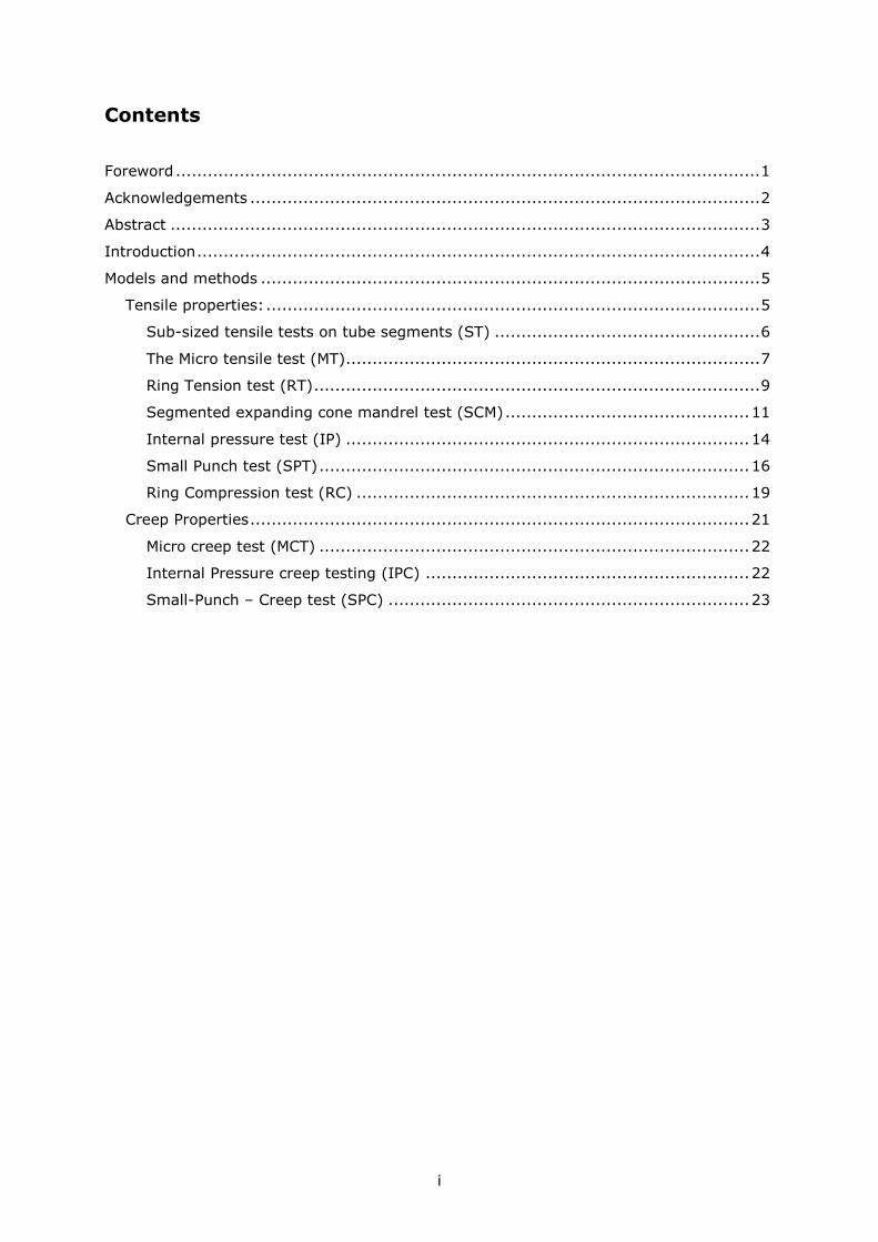
The maximum stress on the stress-strain curve is the ultimate tensile strength Rm. The
yield stress Rp02 is acquired by offsetting the linear fit (passing through origin) line to the
pre-defined (here 0.2%) strain and reading the stress at the location of intersection
between the stress-strain curve and the line as shown in Figure 2.
𝜎 =𝐹
𝐴0
𝜀 =𝐿 − 𝐿0
𝐿0
7
Figure 2. Stress-Strain curve of uniaxial tensile test on curved tube specimen [4]
This test is considered to give the best estimate of the axial material properties of the
cladding tube since it is as close to a "standard" tensile test as possible.
The test features for this test type are estimated as:
● Material needed 16 specimen / 10 cm (as in Figure 1)
● Test simplicity Simple
● Specimen preparation EDM cut (irradiation problematic?)
● Controlled load and displacement YES, same as standard tensile
● Hot-cell applicability Possible
● Testing in corrosive loops Possible
● Biaxiality, controlled or imposed Not applicable
● Strain rate sensitivity Same as for standard tensile test
● Simplicity of assessment Simple
The Micro tensile test (MT)
With the micro-sized tensile test (MT) specimen can be extracted in both the axial
(tensile) and the hoop direction of the thin walled tube. The tensile specimens can for
instance be manufactured by micro electrical discharging machining (EDM) and
polishing.
The specimen size can naturally be optimized to suit the thin walled tube (TASTE: Gauge
length 0.8 mm and cross section 0.3x0.2 mm). Special gripping tools, high sensitivity
loading cells, rigorous specimen alignment procedures and optical displacement
measurement have to be used to ensure that the load-deflection curve becomes
repeatable and that representative estimates for the tensile properties can be acquired.
The specimen and a generalized test setup are shown in Figure 3.
0
100
200
300
400
500
600
700
800
900
0 0.1 0.2 0.3 0.4 0.5 0.6 0.7
Eng.
Str
ess
(M
Pa)
Eng. Strain (%)
Data
Rp02
0
100
200
300
400
500
600
700
800
900
0 1 2 3 4 5
Eng.
Str
ess
(M
Pa)
Eng. Strain (%)
Data
Rp02
Rm

8
Figure 3. Micro-sized uniaxial specimen manufactured from a cladding tube A) and test set-up B).
The translation of the load-deflection to stress-strain curve is done as for the sub-sized
tensile tests (Equations 1 and 2.). Two typical stress-strain curves conducted at room
temperature are shown in Figure 4.
Figure 4. Stress-strain curves from micro specimen room temperature tests.
The determination of both axial and hoop properties can be performed due to the small
specimen size.
The test features for this test type are estimated as:
● Material needed Minimal, large number of specimens
● Test simplicity Difficult (miniature specimen)
● Specimen preparation Difficult (EDM machining)
● Controlled load and displacement Same as standard tensile tests
9
● Hot-cell applicability Difficult
● Testing in corrosive loops Difficult
● Biaxiality, controlled or imposed Not applicable
● Strain rate sensitivity Same as for standard tensile tests
● Simplicity of assessment Simple
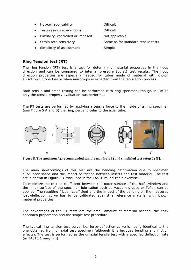
Ring Tension test (RT)
The ring tension (RT) test is a test for determining material properties in the hoop
direction and can be compared to internal pressure (burst) test results. The hoop
direction properties are especially needed for tubes made of material with known
anisotropic properties or when anisotropy is expected from the fabrication process.
Both tensile and creep testing can be performed with ring specimen, though in TASTE
only the tensile property evaluation was performed.
The RT tests are performed by applying a tensile force to the inside of a ring specimen
(see Figure 5 A and B) the ring, perpendicular to the axial tube.
A B C
Figure 5. The specimen A), recommended sample mandrels B) and simplified test setup C) [5].
The main shortcomings of this test are the bending deformation due to specimen
curvilinear shape and the impact of friction between inserts and test material. The test
setup shown in Figure 5-C was used in the TASTE round-robin exercise.
To minimize the friction coefficient between the outer surface of the half cylinders and
the inner surface of the specimen lubrication such as vacuum grease or Teflon can be
applied. The resulting friction coefficient and the impact of the bending on the measured
load-deflection curve has to be calibrated against a reference material with known
material properties.
The advantages of the RT tests are the small amount of material needed, the easy
specimen preparation and the simple test procedure.
The typical ring tension test curve, i.e. force-deflection curve is nearly identical to the
one obtained from uniaxial test specimen (although it is includes bending and friction
effects). The test is performed as the uniaxial tensile test with a specified deflection rate
(in TASTE 1 mm/min).
10
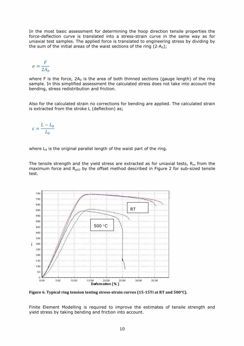
In the most basic assessment for determining the hoop direction tensile properties the
force-deflection curve is translated into a stress-strain curve in the same way as for
uniaxial test samples. The applied force is translated to engineering stress by dividing by
the sum of the initial areas of the waist sections of the ring (2·A0);
where F is the force, 2A0 is the area of both thinned sections (gauge length) of the ring
sample. In this simplified assessment the calculated stress does not take into account the
bending, stress redistribution and friction.
Also for the calculated strain no corrections for bending are applied. The calculated strain
is extracted from the stroke L (deflection) as;
where L0 is the original parallel length of the waist part of the ring.
The tensile strength and the yield stress are extracted as for uniaxial tests, Rm from the
maximum force and Rp02 by the offset method described in Figure 2 for sub-sized tensile
test.
Figure 6. Typical ring tension testing stress-strain curves (15-15Ti at RT and 500°C).
Finite Element Modelling is required to improve the estimates of tensile strength and
yield stress by taking bending and friction into account.
𝜎 =𝐹
2𝐴0
𝜀 =𝐿 − 𝐿0
𝐿0
RT
500 C
Str
ess
(MPa)

11
The main disadvantage of this test methodology is the impact of bending and friction.
The test features for this test type are estimated as:
● Material needed 20 specimen / 10 cm (5 mm rings)
● Test simplicity Simple
● Specimen preparation Medium, EDM waisted tube ring
● Controlled load and displacement Same as for standard tensile test
● Hot-cell applicability Possible
● Testing in corrosive loops Possible
● Biaxiality, controlled or imposed Imposed, impact of bending neglected
● strain rate sensitivity Same as for standard tensile tests
● Simplicity of assessment Simple (friction & bending neglected)
Segmented expanding cone mandrel test (SCM)
The Segmented cone mandrel (SCM) test is used for defining the hoop direction material
properties of nuclear fuel claddings. The loading of SCM is induced by expanding
segments, which are placed inside a cladding tube as seen in Figure 7.
The following inputs are needed for the data analysis;
1. Load-displacement from the test: F vs uz (see typical curve in Figure 8)
2. Ring sample geometry: height, wall thickness and inner diameter
3. Segment geometry : outer geometry and height
4. Cone geometry: angle (20˚ used in TASTE)
5. Friction coefficient between, cone/segment and segment/tube. The friction
coefficient is the major unknown. For steels that are Teflon sprayed a typical
value is 0.05. For steel-to-steel values of 0.15 to 0.2 care considered typical.

12
a) b)
Figure 7.The segmented cone mandrel test.
The stress-strain curves are computed directly from the load-displacement curve and the
geometry of the ring sample and cone.
The axisymmetric analytical model gives an estimate on the stress-strain curve (,) by
assuming purely plastic deformation and therefore no volume change. The known
variables (see Figure 7a) are: the initial height (TH 0 ) and thickness (t0) of the cladding
tube, the diameter (cR02 ) and thickness (tM) of the segments’ lower part and the height
of the segment (sH ), the angle of the cone ( ), the vertical displacement (uz) and
associated force (Fz) and the friction coefficient between the different friction surfaces (
321 ,, ). The unkown parameters are: the contact pressure (p1, p2, p3), the hoop
stress (), the height (TH ) and wall thickness (t) of the tube.

13
t
Rtp
tR
utRHA
RRHARRHAwhere
A
Fp
A
F
p
A
Fp
tR
utt
tR
uHH
tR
u
c
M
GF
F
M
c
zM
cTT
L
ccs
M
ccs
c
L
T
z
M
z
c
z
GF
G
M
c
zGF
F
M
c
zTT
M
c
z
)(
)2/tan(1)(2
])[(],))2/tan([(
]1
1)2/tan(
)2/tan(11
)1)2/tan(
)2/tan(1[(
,)1(
)1)2/tan(
)2/tan(1(1(
,)2/tan(/1(
))2/tan(
1(,))2/tan(
1(),)2/tan(
1ln(
02
0
00
2
000
Pr2
000
Pr
21
12
31
2
23
Pr
12
3
1
Pr1
0
0
0
0
0
Figure 8. Recorded F versus uz for room temperature tests of 15-15Ti.
The main disadvantage of the method is the large impact of friction on estimated yield
and tensile strength.
The test features for this test type are estimated as:
● Material needed 20 specimen / 10 cm (5 mm rings)
● Test simplicity Medium (segment placing tedious)
● Specimen preparation Simple, tube ring
● Controlled load and displacement Yes, both possible
14
● Hot-cell applicability No (numerous small segment parts)
● Testing in corrosive loops Unlikely
● Biaxiality, controlled or imposed Some biaxiality from segments
● Strain rate sensitivity Same as for standard tensile tests
● Simplicity of assessment Medium/difficult (friction unknown)
Internal pressure test (IP)
In the classical internal pressure (IP) test for biaxial tensile and creep testing the stress
state is imposed by internal pressure. In this test set-up, without added tensile loads, the
axial–hoop stress ratio is constant factor of 2, i.e. axial stress is ½ the hoop stress. In
the enhanced version of the test it is possible to control the ratio of hoop and tension
stresses by adding an axial load for the tubular test specimen either in push or pull
direction.
The elastic hoop stress caused by the internal pressure is;
σel hoop =p
y2 − 1∙ (1 + (
Do
2/r)2)
where p is internal pressure, Do is the outer diameter of the tubular specimen, r is the
radius (from the middle point to the point of interest) and y = outer diameter Do divided
by the inner diameter of the tubular specimen.
The elastic axial stress caused by the internal pressure and an imposed axial load can be
calculated as;
σel axial =p
y2 − 1+
Fa
A
where Fa is axial force and A is the cross-sectional area of the tubular specimen.
The elastic radial stress can be calculated:
𝜎𝑒𝑙 𝑟𝑎𝑑 = (𝑃
𝑦2 − 1) ∙ (1 − (
𝐷𝑜
2/𝑟)2)
A number of correlation equations [6] is proposed for transforming tensile strength and
yield stress properties to burst pressure Pmax such as:
A) The ASME correlation;

15
𝑃𝑚𝑎𝑥 = 𝑅𝑚
𝑘 − 1
0.6𝑘 + 0.4
B) The Max Share stress correlation;
𝑃𝑚𝑎𝑥 = 2𝑅𝑚
𝑘 − 1
𝑘 + 1
where k is the ratio between outer and inner radius (Ro/Ri), for the TASTE cladding
dimensions k=3.275/2.825=1.16 is giving Pmax estimates of 0.145·Rm and 0.148·Rm
respectively.
C) The Fletcher correlation, also given in given [6], is dependent on the flow stress
flow=(Rm+Rp02)/2 and the uniform strain u.
𝑃𝑚𝑎𝑥 =2𝜎𝑓𝑙𝑜𝑤
𝐷𝑖(1 −𝜀𝑢
2)
It is to be noted that the biaxial stress state in an internal pressure tests is suppressing
the yielding and the yielding is expected to occur at approximately 1.12 times the
uniaxial yield stress, depending on the ratio inner diameter over wall thickness (D i/t), i.e.
the ratio of hoop stress to von Mises stress.
In TASTE the internal pressure tests were creep tests at constant internal pressure (IPC).
The internal pressure tests for tensile properties are though interesting for fuel pin mock-
up testing.
The main shortcoming of the IP tests are the "large" amount of material needed for the
tests. Furthermore, the IPC instrumentation for measuring the hoop and axial strains are
located along the "gauge length" and hence the load control is a potential problem since
material softening or cracking might lead to undesired fracture. For the IPB test the final
fracture is the sought test result.
The test features for this test type are estimated as:
● Material needed 2 specimens / 10 cm (50 mm tubes)
● Test simplicity Medium (internal pressure)
● Specimen preparation Difficult, leak tightness
● Controlled load and displacement Yes, both possible
● Hot-cell applicability Possible
● Testing in corrosive loops Possible
● Biaxiality, controlled or imposed biaxial in nature, control possible
● Strain rate sensitivity Assumed same as for tensile tests
● Simplicity of assessment Easy (correlation to Rm, Rp02)
16
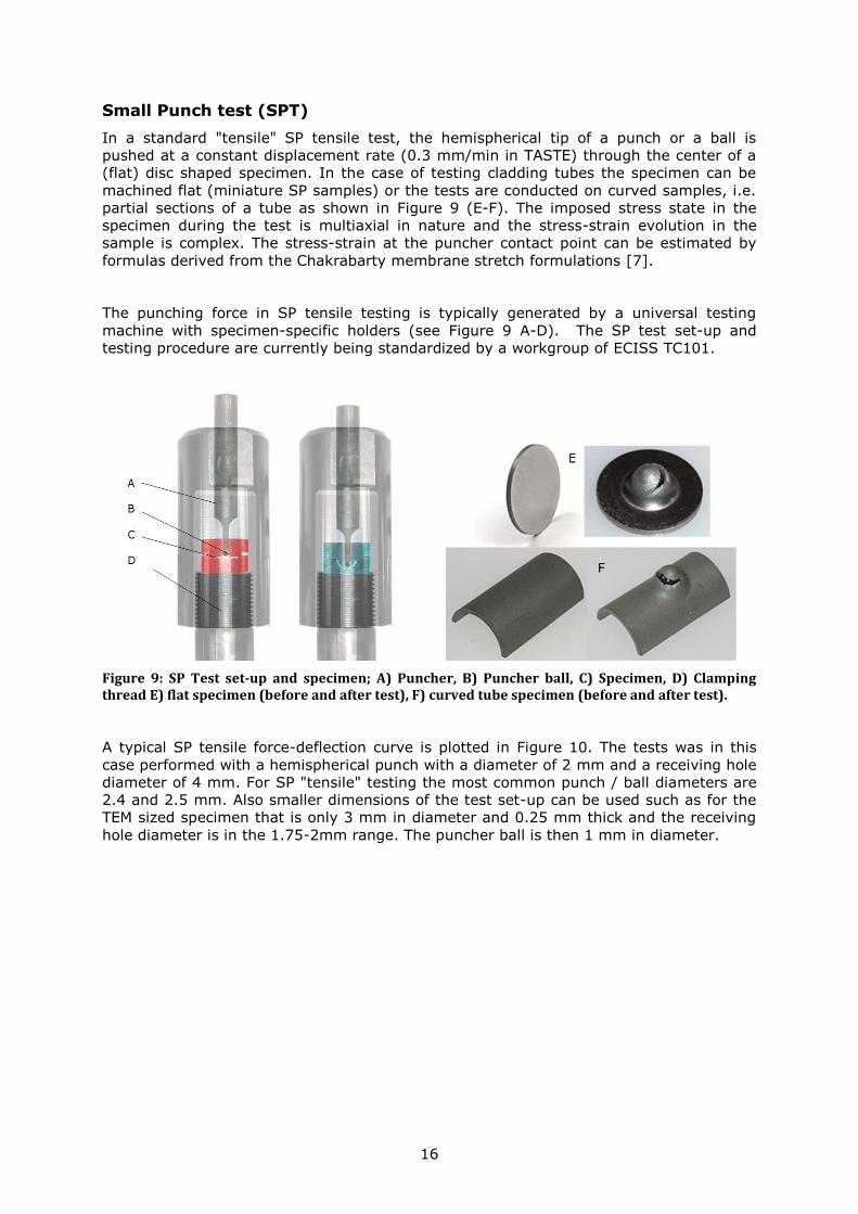
Small Punch test (SPT)
In a standard "tensile" SP tensile test, the hemispherical tip of a punch or a ball is
pushed at a constant displacement rate (0.3 mm/min in TASTE) through the center of a
(flat) disc shaped specimen. In the case of testing cladding tubes the specimen can be
machined flat (miniature SP samples) or the tests are conducted on curved samples, i.e.
partial sections of a tube as shown in Figure 9 (E-F). The imposed stress state in the
specimen during the test is multiaxial in nature and the stress-strain evolution in the
sample is complex. The stress-strain at the puncher contact point can be estimated by
formulas derived from the Chakrabarty membrane stretch formulations [7].
The punching force in SP tensile testing is typically generated by a universal testing
machine with specimen-specific holders (see Figure 9 A-D). The SP test set-up and
testing procedure are currently being standardized by a workgroup of ECISS TC101.
Figure 9: SP Test set-up and specimen; A) Puncher, B) Puncher ball, C) Specimen, D) Clamping thread E) flat specimen (before and after test), F) curved tube specimen (before and after test).
A typical SP tensile force-deflection curve is plotted in Figure 10. The tests was in this
case performed with a hemispherical punch with a diameter of 2 mm and a receiving hole
diameter of 4 mm. For SP "tensile" testing the most common punch / ball diameters are
2.4 and 2.5 mm. Also smaller dimensions of the test set-up can be used such as for the
TEM sized specimen that is only 3 mm in diameter and 0.25 mm thick and the receiving
hole diameter is in the 1.75-2mm range. The puncher ball is then 1 mm in diameter.

17
Figure 10. Force-deflection curve for a tensile SP test on Gr. 91 stainless steel at -100 ºC.
The estimation of the tensile material properties by SPT test is based on three
characteristic values that can be derived from the force-deflection curve, i.e. the
maximum force Fm, the deflection um at maximum force and the elastic-plastic transition
force Fe. Fm is naturally the maximum force of the test. For the determination of Fe
several approaches are currently discussed. In Figure 11 four different approaches are
shown.
Figure 11 Extracting the Fe from the SP force-deflection curve by two-secants, the CWA and the offset method.
It is clear that correlating the yield stress to Fe will have different factors depending on
which method is used.
The classical correlations for determining tensile strength and yield stress are:

18
𝑅𝑝02 = 𝛼1
𝐹𝑒
ℎ02 + 𝛼2
𝑅𝑚 = 𝛽1
𝐹𝑚
ℎ0𝑢𝑚
+ 𝛽2
The , and parameter are correlation constants. Note that these constants are
dependent on the test-setup, i.e. ball diameter, receiving hole diameter and clamping.
To compensate for differences in the test-setup dimensions and specimen thickness good
estimates can be acquired by using the CWA formula intended for use in SP creep
testing.
The ductility of the test material can be estimated by a SP fracture strain;
𝜀𝑓 = ln (ℎ0
ℎ𝑓
)
Where h0 is the initial specimen thickness and hf the thickness adjacent to the area
where failure occurred. The f can also be estimated by the Chakrabarty formula for
thinning in the ball-specimen contact boundary.
ℎ∗ = ℎ0 (𝑐𝑜𝑠𝜃0
𝑐𝑜𝑠𝜃)
2
Where h* is the thickness at the contact boundary and the angles 0 and can be derived
from the deflection. Note that these angles are dependent on the puncher and receiving
hole diameters.
The main disadvantage of this tests is the multi-axial nature of the test and the limited
inter-laboratory comparability induced by the different dimensions of puncher, receiving
hole and clamping. This however will change when the methodology has been
standardized.
Consensus on the best way to convert force to stress, including correlation constants has
not yet been satisfactorily settled, but a promising engineering method will be applied for
the 1515Ti tests results.
The test features for this test type are estimated as:
● Material needed 30 specimen/10 cm (1/3 tube)
● Test simplicity Easy /medium
● Specimen preparation Medium (flat), simple tube sections

19
● Controlled load and displacement Yes, both possible
● Hot-cell applicability Possible
● Testing in corrosive loops Possible
● Biaxiality, controlled or imposed biaxial in nature, control possible
● Strain rate sensitivity Assumed same as for tensile tests
● Simplicity of assessment Easy (correlation to Rm, Rp02)
Ring Compression test (RC)
In ring compression tests (RT) [8] the ring sample is compressed perpendicular to the
tube axis under either displacement or load control. The main use of the ring-
compression test has been as an effective screening test for ductility (aging, radiation
hardening).
The tests can also be used for estimating tensile and creep properties. The main benefit
of the test is the simplicity of the test specimen and test procedure. The main
shortcoming of the method is that the deformation is highly non-homogenous with
simultaneous tensile (outer surface, 3 and 9 o'clock) and compressive (inner surface, 3
and 9 o'clock) stresses. At 12 and 6 o'clock positions the situation is reversed.
A beneficial feature is also that the test method has no sensitivity to friction between the
ring and the loading device.
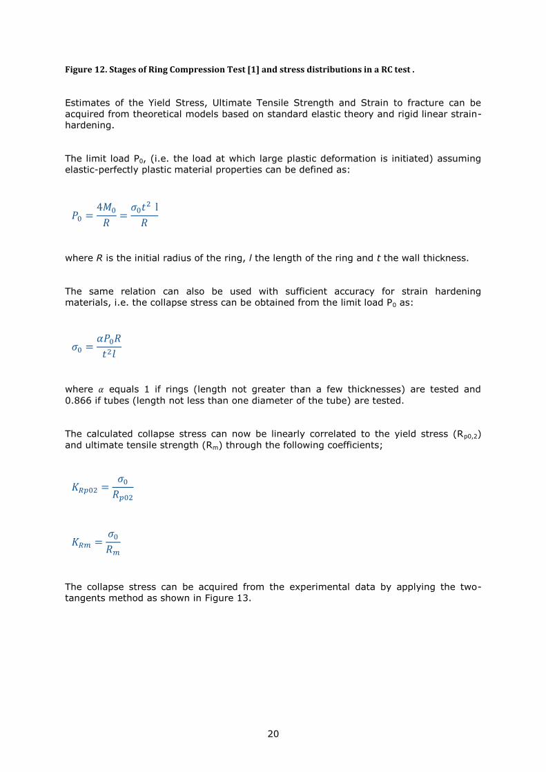
The characteristic RC load-displacement curves are produced by applying a constant
compressive displacement rate (for TASTE 0.2 mm/min). The maximum (equivalent)
stresses are expected to be reached close to the inner surface at the 12 o’clock position
as seen in Figure 12.
Due to the complex dynamic stress/strain evolution in the ring during the test the
translation of the force-deflection curve into an equivalent stress-strain curve is not
attempted in a simplified assessment. Instead a correlation between the descriptive
"collapse" loads and the sought tensile properties are determined. For more advanced
estimates Finite Element Analysis has to be used.
20
Figure 12. Stages of Ring Compression Test [1] and stress distributions in a RC test .
Estimates of the Yield Stress, Ultimate Tensile Strength and Strain to fracture can be
acquired from theoretical models based on standard elastic theory and rigid linear strain-
hardening.
The limit load P0, (i.e. the load at which large plastic deformation is initiated) assuming
elastic-perfectly plastic material properties can be defined as:
where R is the initial radius of the ring, l the length of the ring and t the wall thickness.
The same relation can also be used with sufficient accuracy for strain hardening
materials, i.e. the collapse stress can be obtained from the limit load P0 as:
where 𝛼 equals 1 if rings (length not greater than a few thicknesses) are tested and
0.866 if tubes (length not less than one diameter of the tube) are tested.
The calculated collapse stress can now be linearly correlated to the yield stress (Rp0,2)
and ultimate tensile strength (Rm) through the following coefficients;
The collapse stress can be acquired from the experimental data by applying the two-
tangents method as shown in Figure 13.
𝑃0 =4𝑀0
𝑅=
𝜎0𝑡2 l
𝑅
𝜎0 =𝛼𝑃0𝑅
𝑡2𝑙
𝐾𝑅𝑝02 =𝜎0
𝑅𝑝02
𝐾𝑅𝑚 =𝜎0
𝑅𝑚

21
Figure 13. Extracting the collapse load P0 from experimental data [8].
A clear draw-back of this procedure is that both yield stress and tensile strength are
correlated against the same calculated collapse stress.
The test features for this test type are estimated as:
● Material needed 15 specimen/10 cm (ring)
● Test simplicity Easy
● Specimen preparation Easy
● Controlled load and displacement Yes, both possible
● Hot-cell applicability Possible
● Testing in corrosive loops Possible
● Biaxiality, controlled or imposed multiaxial in nature, imposed
● Strain rate sensitivity Assumed same as for tensile tests
● Simplicity of assessment Easy (correlation to Rm, Rp02)
Creep Properties
The main sought creep properties are the strengths (to rupture Ru/T/t or specified strain
R/T/t) as a function of temperature (T) and time (t), for instance the rupture strength at
600°C to give a life of 10 000h is Ru/600°C/10kh. To estimate rupture strength values only
the time to rupture is needed for a test at specified temperature and stress. For a creep
strain assessment also the time-strain evolution is needed for the specified stress and
temperature.

22
Micro creep test (MCT)
The micro creep test is performed with specimen and equipment equivalent with the ones
presented earlier for the micro tensile test. Creep tests differ only in the loading / stress
state, i.e. creep tests are performed in constant load.
The strain-time creep curves at specified constant load can be used in the same manner
as for standard creep test [9].
The test features for this test type are estimated as:
● Material needed Minimal, large amount of specimen
● Test simplicity Difficult (miniature specimen)
● Specimen preparation Difficult (EDM machining)
● Controlled load and displacement YES, same as standard tensile
● Hot-cell applicability Difficult
● Testing in corrosive loops Difficult
● Biaxiality, controlled or imposed Not applicable
● Strain rate sensitivity Not applicable
● Simplicity of assessment Simple
Internal Pressure creep testing (IPC)
Internal pressure testing of thin walled tubes can be performed with rather simple
equipment when targeting only to record the rupture time at specified constant pressure.
The IPC creep test requires that a constant pressure can be upheld during the testing,
i.e. the volume change due to diametric changes have to be compensated for.
For acquiring creep strain information the test set-up has to be much more complex since
the measurement of diametric change is during the test is challenging. The measurement
can of course be performed by interrupted testing and measurement of the permanent
diametric change. This approach is however time consuming and the interruptions can
cause differences in the total rupture time by potentially introducing repeated primary
creep response.
For the enhanced IPC test rigs it is also possible to change the biaxial stress state by
applying additional axial load. This feature is needed if the anisotropic material properties
are targeted. In the case of the purely internal pressure test the ratio of hoop to axial
stress is a factor of 2.
For steady state creep stresses, the hoop stress for creep is:
𝜎𝐶𝑟 ℎ𝑜𝑜𝑝 = 𝑃/(𝑦2/n − 1) · (1 + ((2 − 𝑛)
𝑛) · (
𝐷𝑜
2/𝑟)2/𝑛)
(5)
Where n is the creep exponent for the power-law creep. The axial stress for creep is:
23
σCr axial = P/(y2/n − 1) · (1 + ((1 − n)
𝑛) · (
Do
2/r)2/n) +
FaA⁄
(6)
The radial stress for creep can be calculated:
𝜎𝐶𝑟 𝑟𝑎𝑑 = 𝑃/(𝑦2/n − 1) · (1 − (𝐷𝑜
2/𝑟)2/𝑛)
(7)
The Von Mises stress for creep can be calculated as follows:
𝜎𝐶𝑟 𝑉𝑀 =1
√2· √((𝜎𝐶𝑟 ℎ𝑜𝑜𝑝−𝜎𝐶𝑟 𝑎𝑥𝑖𝑎𝑙)2 + (𝜎𝐶𝑟 𝑎𝑥𝑖𝑎𝑙 − 𝜎𝐶𝑟 𝑟𝑎𝑑)2 + (𝜎𝐶𝑟 𝑟𝑎𝑑 − 𝜎𝐶𝑟 ℎ𝑜𝑜𝑝)2 (8)
The skeletal stress can be calculated as:
σskeletal = P ·√3
y2 − 1· (
(y2 − 1)
n/(y2/n − 1))n/(n−1) (9)
The main drawback of this test is the complex measurement set-up needed for
measuring diametric (hoop) strains since the location where the main deformation occurs
is not necessarily mid tube. Also for the creep life assessment the choice of reference
stress is not always clear. The potential candidates for stress-rupture can be hoop stress,
the von-Mises stress or the skeletal stress.
The test features for this test type are;
● Material needed 2-3 specimens / 10 cm (30 mm tubes)
● Test simplicity Medium/difficult (diametric strain)
● Specimen preparation Difficult, leak tightness
● Controlled load and displacement Yes, both possible
● Hot-cell applicability Possible
● Testing in corrosive loops Possible
● Biaxiality, controlled or imposed biaxial in nature, control possible
● Strain rate sensitivity Not applicable
● Simplicity of assessment Medium (use hoop, VM or skeletal?)
Small-Punch – Creep test (SPC)
For SPC testing there are several different test machine designs. The most common
being the top loaded dead weight machine. The SPC test is conducted with the same
test-setup and samples as for the SPT test except the loading mode is constant load. A
SPC time-deflection curve is given in Figure 14 to be compared with a uniaxial creep

24
curve in Figure 15. In Figure 16 some P91 SPC creep rupture results plotted showing
(expected) scatter between different types of testing machines.
Figure 14. . SP creep deflection and deflection rate as a function of time for a 600 °C / 364 N test.
Figure 15. Uniaxial creep strain and strain rate as a function of time for a 600 °C / 155 MPa test.
0.001
0.01
0.1
1
10
100
1000
0
200
400
600
800
1000
1200
1400
1600
1800
0 20000 40000 60000 80000 100000 120000
De
fle
ctio
n r
ate
, m
/s
Def
lect
ion
, m
Time [s]
SP test 600°C / 350N
Total deflection
Deflection rate
ItI/tr 30%
IItII/tr 50%
IIItIII/tr 20%
DII/Dmax 15%
DIII/Dmax 25%
DI/Dmax 60%
1.E-05
1.E-04
1.E-03
1.E-02
0.00
0.02
0.04
0.06
0.08
0.10
0.12
0.14
0.16
0.18
0.20
0.0E+00 5.0E+05 1.0E+06 1.5E+06 2.0E+06 2.5E+06
stra
in r
ate
, 1/h
Stra
in
Time [s]
Uniaxial creep test 600°C / 155 MPa
creepl strain
strain rate
ItI/tr 12% II
tII/tr 48%
IIItIII/tr 40%
II/f 9%
I/f 7%
III/f 84%

25
Figure 16. SPC creep rupture test results at 625°C for P91 steel. The data is from 3 different testing machines.
SPT creep tests have been successfully used for assessing a range of ductile materials
(mainly F/M steels used in conventional power plants). The tests have also been used for
ranking semi-brittle to brittle super alloys at high temperatures.
The main challenge of SPC as a testing technique to estimate the uniaxial creep
properties is the conversion ratio of the load in a SPC test (F) into the corresponding
stress () in a uniaxial creep test. In the current CoP [10] the following relationship is
given for the load over stress ratio F/;
hrRkF SPSP 2.12.033.3/ (10)
where R is the radius of the receiving hole, r the radius of the puncher or ceramic ball, h
the specimen thickness and kSP is the non-dimensional SP ductility parameter. The
default value of kSP=1. However, it has been shown that the kSP parameter deviates from
unity for a number of materials and especially for longer test durations.
It was found that the creep tests performed with the target TASTE material 1515 Ti
behaved in a creep-brittle fashion. Early cracking of the material in the initial phase of
loading or creep before reaching "steady state" creep straining makes assessment of
both rupture and creep deflection rate impossible. The few tests performed with a smaller
puncher ball (2 mm instead of the 2.5 mm) had seemingly less cracking issues and
could potentially indicate that testing with the TEM disk size specimen and the 1 mm
ball could be successful.
The main draw-back of this test is the complex multi-axial stress state and the unclear
Force to stress conversion factor.

26
The test features for this test type are;
● Material needed 30 specimen/10 cm (1/3 tube)
● Test simplicity Easy /medium
● Specimen preparation Medium (flat), Simple tube sections
● Controlled load and displacement Not applicable
● Hot-cell applicability Possible
● Testing in corrosive loops Possible
● Biaxiality, controlled or imposed multi-axial in nature
● Strain rate sensitivity Not applicable
● Simplicity of assessment Medium (correlation to Rm, Rp02)

27
Discussion
The TASTE test programme has made it possible to compare a number of test techniques
requiring different amount of material. The large amount of data acquired on the
different test types for 1515Ti steel will give an improved insight in the usability,
simplicity and robustness of estimates of each technique.
It is suggested that the testing of fuel cladding materials and sub-sized specimen
techniques are continued within the EEAR JPNM for further insight in this important topic.
References
[1] Holmstrom S. et. al, Determination of high temperature material properties of 15-
15 steel by small specimen techniques. "TASTE", EERA JPNM Pilot project report.
JRC105589, To be published as public report 2017.
[2] International Standard ISO 6892-1:2016, Metallic materials-Tensile testing, Part1:
Method of test at room temperature.
[3] International Standard ISO 6892-2:2011, Metallic materials-Tensile testing, Part2:
Method of test at elevated temperature.
[4] Altstadt E., Houska M., Mechanical Properties of 15-15 Ti based on small specimen
testing. HZDR report for TASTE, 2016.
[5] Radu V., Nitu A, Pitigoi V., Analyses of the Ring Tension Tests performed on the
15-15Ti tube specimens, RATEN ICN status report for TASTE, 2016.
[6] Law M., Bowie G., Prediction of failure strain and burst pressure in high yield-to-
tensile strength ratio linepipe. International Journal of Pressure Vessels and Piping
84, pp. 487–492, 2007
[7] Chakrabarty, J., theory of stretch forming over hemispherical punch heads,
International Journal of Mechanical Sciences, Volume 12, Issue 4, pp. 315-325,
1970
[8] Cristalli C., Ring Compression Tests at room temperature to predict YS and UTS,
ENEA status report for TASTE, 2016.
[9] International Standard ISO 204:2009, Metallic materials — Uniaxial creep testing
in tension — Method of test.
[10] CEN Workshop Agreement CWA 15627: Small Punch Test Method for Metallic
Materials: European Committee for Standardization, CWA 15627: 2007

GETTING IN TOUCH WITH THE EU
In person
All over the European Union there are hundreds of Europe Direct information centres. You can find the address of the centre nearest you at: http://europea.eu/contact
On the phone or by email
Europe Direct is a service that answers your questions about the European Union. You can contact this service:
- by freephone: 00 800 6 7 8 9 10 11 (certain operators may charge for these calls),
- at the following standard number: +32 22999696, or
- by electronic mail via: http://europa.eu/contact
FINDING INFORMATION ABOUT THE EU
Online
Information about the European Union in all the official languages of the EU is available on the Europa website at: http://europa.eu
EU publications You can download or order free and priced EU publications from EU Bookshop at:
http://bookshop.europa.eu. Multiple copies of free publications may be obtained by contacting Europe
Direct or your local information centre (see http://europa.eu/contact).

KJ-N
A-2
8642-E
N-N
doi:10.2760/702821
ISBN 978-92-79-69515-5