Test Equipment Solutions Datasheet · Test Equipment Solutions Datasheet ... presenting flexible...
16
Test Equipment Solutions Datasheet Test Equipment Solutions Ltd specialise in the second user sale, rental and distribution of quality test & measurement (T&M) equipment. We stock all major equipment types such as spectrum analyzers, signal generators, oscilloscopes, power meters, logic analysers etc from all the major suppliers such as Agilent, Tektronix, Anritsu and Rohde & Schwarz. As well as the headline benefit of cost saving, second user offers shorter lead times, higher reliability and multivendor solutions. Rental, of course, is ideal for shorter term needs and offers fast delivery, flexibility, try-before-you-buy, zero capital expenditure, lower risk and off balance sheet accounting. Both second user and rental improve the key business measure of Return On Capital Employed. All products supplied by Test Equipment Solutions include: Email: [email protected] Web: www.TestEquipmentHQ.com We are focused at the professional end of the marketplace, primarily working with customers for whom high performance, quality and service are key, whilst realising the cost savings that second user equipment offers. As such, we fully test & refurbish equipment in our in-house, traceable Lab. Items are supplied with manuals, accessories and typically a full no-quibble 1 year warranty. Our staff have extensive backgrounds in T&M, totalling over 150 years of combined experience, which enables us to deliver industry-leading service and support. We endeavour to be customer focused in every way right down to the detail, such as offering free delivery on sales, presenting flexible technical + commercial solutions and supplying a loan unit during warranty repair, if available. We are based at Aldermaston in the UK from where we supply test equipment worldwide. Our facility incorporates Sales, Support, Admin, Logistics and our own in-house Lab. - No-quibble parts & labour warranty (we provide transport for UK mainland addresses). - Free loan equipment during warranty repair, if available. - Full electrical, mechanical and safety refurbishment in our 40GHz in-house Lab. - Certificate of Conformance (calibration available on request). - Manuals and accessories required for normal operation. - Free insured delivery to your UK mainland address (sales). - Support from our team of seasoned Test & Measurement engineers. - ISO9001 quality assurance. T: 01183 800 800 F: 01183 800 804 Test Equipment Solutions Ltd Unit 3 Zodiac House Calleva Park Aldermaston Berkshire RG7 8HN
Transcript of Test Equipment Solutions Datasheet · Test Equipment Solutions Datasheet ... presenting flexible...

Test Equipment Solutions Datasheet
Test Equipment Solutions Ltd specialise in the second user sale, rental and distribution of quality test & measurement (T&M) equipment. We stock all major equipment types such as spectrum analyzers, signal generators, oscilloscopes, power meters, logic analysers etc from all the major suppliers such as Agilent, Tektronix, Anritsu and Rohde & Schwarz.
As well as the headline benefit of cost saving, second user offers shorter lead times, higher reliability and multivendor solutions. Rental, of course, is ideal for shorter term needs and offers fast delivery, flexibility, try-before-you-buy, zero capital expenditure, lower risk and off balance sheet accounting. Both second user and rental improve the key business measure of Return On Capital Employed.
All products supplied by Test Equipment Solutions include:
Email: [email protected]: www.TestEquipmentHQ.com
We are focused at the professional end of the marketplace, primarily working with customers for whom high performance, quality and service are key, whilst realising the cost savings that second user equipment offers. As such, we fully test & refurbish equipment in our in-house, traceable Lab. Items are supplied with manuals, accessories and typically a full no-quibble 1 year warranty. Our staff have extensive backgrounds in T&M, totalling over 150 years of combined experience, which enables us to deliver industry-leading service and support. We endeavour to be customer focused in every way right down to the detail, such as offering free delivery on sales, presenting flexible technical + commercial solutions and supplying a loan unit during warranty repair, if available.
We are based at Aldermaston in the UK from where we supply test equipment worldwide. Our facility incorporates Sales, Support, Admin, Logistics and our own in-house Lab.
- No-quibble parts & labour warranty (we provide transport for UK mainland addresses).- Free loan equipment during warranty repair, if available.- Full electrical, mechanical and safety refurbishment in our 40GHz in-house Lab.- Certificate of Conformance (calibration available on request).- Manuals and accessories required for normal operation.- Free insured delivery to your UK mainland address (sales).- Support from our team of seasoned Test & Measurement engineers.- ISO9001 quality assurance.
T: 01183 800 800 F: 01183 800 804
Test Equipment Solutions LtdUnit 3 Zodiac HouseCalleva ParkAldermastonBerkshireRG7 8HN
Features & Benefits
3.5 GHz bandwidth model for serialand digital applications
2.5 GHz, 1 GHz and 500 MHz band-width models for all applications
Up to 40 GS/s real-time sample rateon one channel and up to 10 GS/son all four channels
Up to 400 megasamples recordlength with MultiView Zoom™ featurefor quick navigation
>250,000 WFMS/s maximum wave-form capture rate
User-selectable bandwidth limit filters for better low-frequency measurement accuracy
MyScope® custom windows and rightmouse click menus for exceptionalefficiency
Event search and mark to facilitatethe comprehension of event relationships
Pinpoint® triggering provides themost flexible and highest perform-ance triggering, with over 1400combinations to address virtuallyany triggering situation.
Small footprint and light weight
12.1 largest XGA touch-screendisplay in the industry
Communications mask testing
Clock recovery from serial datastreams
64 bit NRZ serial pattern trigger forisolation of pattern-dependenteffects up to 1.25 Gb/s
NRZ serial test pattern triggering
Low-speed serial protocol triggering(I2C, SPI, RS-232, CAN)
Technology-specific software solutionsprovide built-in domain expertise forEthernet, USB 2.0 compliancetesting, jitter, timing, eye diagram,power, DDR memory bus analysis,CAN and LIN network design
OpenChoice® software with MicrosoftWindows XP OS enables built-innetworking and extended analysis
Applications
Signal integrity, jitter and timing analysis
Verification, debug and characteriza-tion of sophisticated designs
Debugging and compliance testingof serial data streams for telecomand datacom industry standards
Low-speed serial bus design (I2C,SPI, CAN, LIN, RS-232)
Investigation of transient phenomena
Power measurements and analysis
Spectral analysis
Digital Phosphor Oscilloscopes DPO7000 Series
Unmatched Performance for Greater Insight Into Your Design toGet Your Work Done Faster The DPO7000 Series are the newgeneration of real-time digital phosphoroscilloscopes and are the industry’sbest solution to the challenging signalintegrity issues faced by designers veri-fying, characterizing, debugging andtesting sophisticated electronic designs.
The family features exceptional perfor-mance in signal acquisition and analysis,operational simplicity and unmatcheddebugging tools to accelerate your day-to-day tasks. The largest screen in theindustry and the intuitive user interfaceprovide easy access to the maximumamount of information.
Unmatched AcquisitionPerformance
Signal Fidelity of TektronixOscilloscopes Ensures Confidencein Your Measurement Results
– High sample rate on all models, on all channels,to capture more signal details (transients,imperfections, fast edges)
– 40 GS/s on one channel on the 2.5 GHz and3.5 GHz models
– Option 2SR to double the maximum real-timesample rate for the 500 MHz and 1 GHz models
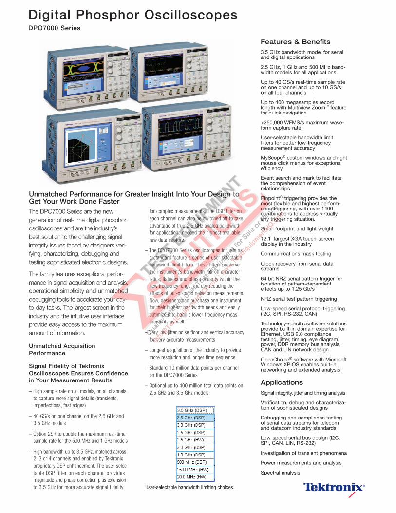
– High bandwidth up to 3.5 GHz, matched across2, 3 or 4 channels and enabled by Tektronixproprietary DSP enhancement. The user-selec-table DSP filter on each channel providesmagnitude and phase correction plus extensionto 3.5 GHz for more accurate signal fidelity
for complex measurements. The DSP filter oneach channel can also be switched off to takeadvantage of true 2.5 GHz analog bandwidthfor applications needed the highest availableraw data capture.
– The DPO7000 Series oscilloscopes include asa standard feature a series of user-selectablebandwidth limit filters. These filters preservethe instrument’s bandwidth roll-off character-istics, flatness and phase linearity within thenew frequency range, thereby reducing theeffects of out-of-band noise on measurements.Now, designers can purchase one instrumentfor their highest bandwidth needs and easilyoptimize it to handle lower-frequency meas-urements as well.
– Very low jitter noise floor and vertical accuracyfor very accurate measurements
– Longest acquisition of the industry to providemore resolution and longer time sequence
– Standard 10 million data points per channelon the DPO7000 Series
– Optional up to 400 million total data points on2.5 GHz and 3.5 GHz models
User-selectable bandwidth limiting choices.

Digital Phosphor Oscilloscopes DPO7000 Series
DPO7000 Series • www.tektronix.com/oscilloscopes2
– Optional up to 200 million total data points onthe 500 MHz and 1 GHz models
– Easily manage this deep record length, providedetailed comparison and analysis of multiplewaveform segments with the MultiView Zoom™
feature. Automatically scroll through deeprecords visually or create a math expression toinstantly highlight differences
– Highest performance probing solutions fordifferential and single-ended voltage signalsas well as current measurement, becauseaccurate design verification depends on high-bandwidth access to critical signals and high-fidelity signal capture
Unmatched Versatility
Get the Most of Your Oscilloscopeby Fully Controlling its WaveformAcquisition and Display Parameters
You have the choice of three horizontaltime base modes of operations. If youare simply doing signal exploration andwant to interact with a lively signal, youwill use the Automatic or interactivedefault mode that provides you with theliveliest display update rate. If you wanta precise measurement and the highestreal-time sample rate that will give youthe most measurement accuracy, thenthe Constant Sample Rate mode is foryou. It will maintain the highest samplerate and provide the best real-timeresolution. The last mode is called theManual mode because it ensures directand independent control of the samplerate and record length.
With the MyScope® Feature, CreateYour Own Control Windows WithOnly the Controls, Features andCapabilities that You Care About
Easily create your own personalized“toolbox” of oscilloscope features in amatter of minutes using a simple, visual,drag-and-drop process. Once created,these custom control windows areeasily accessed through a dedicatedMyScope button and menu selection onthe oscilloscope button/menu bar, justlike any other control window. You canmake an unlimited number of customcontrol windows, enabling each personwho uses the oscilloscope in a sharedenvironment, to have their own uniquecontrol window. MyScope controlwindows will benefit all oscilloscopeusers, eliminating the ramp-up time thatmany face when returning to the labafter not using an oscilloscope for awhile and enables the power user to befar more efficient. Everything you need isfound in one control window rather thanhaving to constantly navigate throughmenu after menu to repeat similar tasks.
With OpenChoice® Software,Customize Your Test andMeasurement System withFamiliar Analysis Tools
The analysis and networking features ofOpenChoice software add flexibility toTektronix’ Windows XP oscilloscopes:Using the fast embedded bus, wave-form data can be moved directly fromacquisition to analysis applications onthe Windows desktop at much fasterspeeds than conventional GPIB trans-fers. Tektronix’ implementation ofindustry standard protocols, such asTekVISA™ interface and ActiveXcontrols, are included for using andenhancing Windows applications fordata analysis and documentation. IVI-COM instrument drivers are included toenable easy communication with theoscilloscope using GPIB, serial dataand LAN connections from programsrunning on the instrument or anexternal PC. Or, use the SoftwareDeveloper’s Kit (SDK) to help create
Zoom in on four areas of interest simultaneouslyto compare them.
Tektronix Active probes achieve high-speedsignal acquisition and measurement fidelity.
3 modes of operation of the horizontal time base.
Drag and drop menu items of interest to createthe MyScope control window.
Capture data into Microsoft Excel using the uniqueExcel toolbar and create custom reports usingthe Word toolbar.

Digital Phosphor Oscilloscopes DPO7000 Series
DPO7000 Series • www.tektronix.com/oscilloscopes 3
custom software to automate multistepprocesses in waveform collection andanalysis with Visual BASIC, C, C++,MATLAB, LabVIEW, LabWindows/CVIand other common ApplicationDevelopment Environments (ADE).Integration of the oscilloscope withexternal PCs and non-Windows hostsis also supported by the DPO7000Series software solutions. In addition,the OpenChoice architecture provides acomprehensive software infrastructurefor faster, more versatile operations.Data transfer programs, such as theExcel or Word toolbar, are used to simplifyanalysis and documentation on theWindows desktop or on an external PC.
Accelerate the Debug ofComplex Electrical Designs
FastAcq Acquisition ModeExpedites Debugging by ClearlyShowing Imperfections
More than just color-grading, FastAcqenabled by Tektronix proprietary DPX®
acquisition technology, captures signalsup to more than 250,000 waveformsper second on all 4 channels simulta-neously, dramatically increasing theprobability of discovering infrequentfault events. And with a simple turn ofthe intensity knob you can clearly see“a world others don’t see,” becausefrequency of occurrence is color coded.Some oscilloscope vendors claim highwaveform capture rates for short burstsof time, but only the DPO7000 Series,
enabled by DPX technology, can deliverthese fast waveform capture rates on asustained basis — saving minutes, hoursor even days by quickly revealing thenature of faults so sophisticated triggermodes can be applied to isolate them.
The Ability to Trigger anOscilloscope on Events of Interestis Paramount in Complex SignalDebug and Validation
Whether you’re trying to find a systemerror or need to isolate a section of acomplex signal for further analysis, likea DDR read or write burst, Tektronix’Pinpoint® triggering provides the solu-tion. The Pinpoint trigger system usesSilicon Germanium (SiGe) technology toprovide trigger sensitivity of up to thebandwidth of the instrument and allowsselection of most trigger types on bothA and B trigger circuits. It can capturevery narrow glitches with very littletrigger jitter. Other trigger systems offermultiple trigger types only on a singleevent (A event), with delayed trigger (Bevent) selection limited to edge typetriggering and often do not provide away to reset the trigger sequence if theB event doesn’t occur. But Pinpointtriggering provides a full suite ofadvance trigger types on both A and Btriggers with reset triggering to beginthe trigger sequence again after aspecified time, state or transition so thateven events in the most complex signalscan be captured. Other oscilloscopes
typically offer less than 20 trigger combi-nations; Pinpoint triggering offers over1400 combinations, all at full perform-ance.
With enhanced triggering, you canchoose to compensate for the differencein time there is between the trigger pathand the display path and eliminate virtu-ally any trigger jitter at the trigger point.In this mode, the trigger point can beused as a measurement reference.
Trigger on the Most Relevant BitSequence of the Industry StandardSerial Bus
I2C (Inter-Integrated Circuit) triggering isa standard feature and includes Startcondition, Missing Acknowledge,Restart, Data Read, Address and/orData Frame, in a 10 bit or 7 bit formatwith a specific selection to choosewhether or not to include the R/W bit.
SPI (Serial Peripheral Interface) triggeringis a standard feature and includes trig-gering on a data pattern within a user-definable frame. RS-232 triggering is astandard feature.
CAN (Controller Area Network) trig-gering is an optional feature (Opt. LSA)and includes synchronization to theStart or End of a CAN frame on anyCAN high or CAN low signal, triggeringon Type of Frame (Data, Remote,Overload), Identifier, Data, MissingAcknowledge and Bit Stuffing error.
Maximize the probability of capturing elusiveglitches and other infrequent events withFastAcq acquisition mode.
Isolate glitches down to 200 ps wide. Isolate, setup and hold violations down to 360 ps.

Digital Phosphor Oscilloscopes DPO7000 Series
Analog HDTV/EDTV Triggering foremerging standards like 1080i, 1080p,720p and 480p as well as standardvideo triggering on any line within afield, all lines, all fields, odd or evenfields for NTSC, SECAM and PAL videosignals. In addition, IRE and mV gratic-ules can be selected for easier meas-urements and visual inspection. This isa standard feature.
Serial Pattern Triggering: To debugserial architectures, use the serialpattern triggering option for NRZ serialdata stream with built-in clock recovery(available on models DPO7254 andDPO7354 only). The instrument canrecover the clock signal, identify thetransitions and decode characters andother protocol data. With the combina-tion of the Serial Trigger and ProtocolDecode software, you can see thecaptured bit sequences decoded intotheir words for convenient analysis (for8 b/10 b and other encoded serial datastreams) or you can set the desiredencoded words for the serial patterntrigger to capture. This serial triggeroption covers NRZ serial standards upto 1.25 Gb/s.
Pattern Lock Triggering adds a newdimension to NRZ serial pattern trig-gering by enabling the oscilloscope totake synchronized acquisitions of a longserial test pattern with outstanding timebase accuracy. Pattern lock triggeringcan be used to remove random jitterfrom long serial data patterns. Effects ofspecific bit transitions can be investi-gated and averaging can be used withmask testing. This feature is includedas part of Option PTM on theDPO7254 and 7354 models.
Large 12.1-inch XGA Display Screen
The DPO7000 Series has the largestdisplay in the industry with a 12.1" XGAtouch screen that gives up to 15%more waveform display than otheroscilloscope series in its class.
10 vertical divisions give you 25% morevertical measurement resolution.
Unmatched Usability
The TekVPI™ probe interface providesversatility and ease of use enabled byintelligent bi-directional oscilloscope-to-probe communication.
The DPO7000 Series are fast-responding instruments and contain acomprehensive suite of features, suchas a touch-screen, shallow menu struc-tures, intuitive graphical icons, knob perchannel vertical controls, support forright mouse clicks, mouse wheelimprovements, saving of waveformsand measurements available in Previewmode, Export/Save/Recall menuimprovements.
Interoperability with LogicAnalyzers for Digital Designand Debug
Tektronix’ Integrated View (iViewTM )data display enables digital designers tosolve signal integrity challenges andeffectively debug and verify theirsystems more quickly and easily. Thisintegration allows designers to viewtime-correlated digital and analog datain the same display window and isolatethe analog characteristics of the digitalsignals that are causing systems fail-ures. No user calibration is required.And, once set up, the iView feature iscompletely automated.
DPO7000 Series • www.tektronix.com/oscilloscopes4
Easily trigger on a specific I2C address. Triggering on an analog HDTV tri-level sync signaland examining horizontal blanking interval.
Serial pattern triggering to debug patterndependent issues.

DPO7000 Series • www.tektronix.com/oscilloscopes 5
Digital Phosphor Oscilloscopes DPO7000 Series
More Insight into YourComplex Electrical Designfor Characterization andCompliance Testing
Such as a simple math expression,waveform mask testing, a pass/failcompliance test, event searching, eventmarking or a custom application thatyou develop yourself, the DPO7000Series Oscilloscopes offer the industry’smost comprehensive set of analysisand compliance tools.
A Wide Range of Built-in AdvancedWaveform Analysis Tools
Waveform cursors make it easy tomeasure trace-to-trace timing charac-teristics, while cursors that link betweenYT and XY display modes make it easyto investigate phase relationships andSafe Operating Area violations. Selectfrom 53 automatic measurementsusing a graphical palette that logicallyorganizes measurements into Amplitude,Time, Combination, Histogram andCommunications categories. Gatherfurther insight into your measurementresults with statistical data such asmean, min, max, standard deviationand population.
Define and apply math expressions towaveform data for on-screen results interms that you can use. Accesscommon waveform math functions withthe touch of a button. Or, for advancedapplications, create algebraic expres-sions consisting of live waveforms,reference waveforms, math functions,measurement values, scalars and useradjustable variables with an easy-to-use calculator-style editor.
FFT – To analyze your signal in thespectral domain, use the basic spectral(provides you with the best parameter)or use advanced spectral with themanual time base horizontal mode(to directly control the frequency span,center frequency and resolutionbandwidth).
Filtering – Enhance your ability toisolate or remove some importantcomponent of your signal (noise orspecific harmonics of the signal) bycreating your own filters or usingthe filters provided as standard withthe instrument.
How does 12.1" display compare to the display size of other oscilloscopes? An integrated toolset for digital design and troubleshooting.
Basic spectral UI control window.

Digital Phosphor Oscilloscopes DPO7000 Series
Jitter, Timing and EyeDiagram Analysis
Jitter, Timing and Eye DiagramAnalysis (Opt. DJA) – Tight timingmargins associated with today’s serialbuses demand stable, low jitterdesigns. DPOJET extends the oscillo-scope capability by making jitter, timingand eye diagram measurements overcontiguous clock and data cycles in asingle-shot real-time acquisition. Withmultiple measurements and a variety ofanalysis tools including spectral andtrend plots, DPOJET quickly showssystem timing under variable condi-tions. It also provides Rj/Dj on signalswithout a repeating pattern and withoutrequiring a fixed pattern or length. Youcan get insight into the signal charac-teristics like SSC profile using theanalysis features and perform pass-failtesting using eye-diagram masks andlimit files for testing against statisticallimits using the compliance features.
This tool is available for the DPO7000Series as Opt. DJA and Opt. DJE.
Advanced Event Search and Mark(Opt. ASM) – Event Search and Markwill relieve the user from the tedioustask of examining data by highlightingimportant events, skipping the unim-portant ones and enhancing thecomprehension of event relationships.
You can navigate between the eventsof interest effortlessly. A basic event(edge-only) search and mark isprovided as a standard feature; andsupport for more advanced event typeslike transition, setup and hold or logicpattern, is provided with the ASM option.
Limit Testing (Opt. LT) – This featureconsists of comparing an acquiredwaveform to boundaries. These bound-aries are typically defined by the user tospecify a tolerance band around areference waveform. If any part of theacquired waveform falls outside of thelimit, the software returns a failuremessage and the location of the failureis shown on the waveform.
Communications Mask Testing (Opt.MTM) – This feature provides acomplete portfolio of masks for verifyingcompliance to serial communicationsstandards. It supports 156 StandardsMasks –
– ITU-T (64 Kb/s to 155 Mb/s)
– ANSI T1.102 (1.544 Mb/s to 155 Mb/s)
– Ethernet IEEE 902.3, ANSI X3.263 (125 Mb/sto 1.25 Gb/s)
– Sonet/SDH (51.84 Mb/s to 622 Mb/s)
– Fibre Channel (133 Mb/s to 2.125 Gb/s)
– USB (12 Mb/s to 480 Mb/s)
– IEEE 1394 (491.5 Mb/s to 1.966 Gb/s)
– RapidI/O (up to 2 Gb/s)
– OIF Standards (1.244 Gb/s)
– Video (143.18 Mb/s to 1.485 Gb/s)
CAN and LIN Timing and ProtocolDecode Software (Opt. LSA) – Whenyou need to ensure seamless and reli-able operation of a CAN or LIN network,this option enables CAN bus triggeringand provides the solution to measureoscillator tolerance, propagation delayand simultaneously decode CAN andLIN messages, with the protocol lever-aging the trigger capabilities.
This option is offered on DPO7354,DPO7254, DPO7104 and DPO7054 asOpt. LSA.
Optional Power Measurement andAnalysis (Opt. PWR) – Analyze powerdissipation in power supply switchingdevices and magnetic components andgenerate detailed reports in customiz-able formats. The HiRes acquisitionmode delivers greater than 8 bits ofvertical resolution on single-shot orrepetitive signals at bandwidth up to125 MHz. The powerful and flexiblemeasurements, math and math-on-math capabilities make it an ideal solu-tion for performing power measure-ments, such as voltage, current, instan-taneous power and energy, for power-device designers. The new TekVPI™
interface provides smart communicationbetween the oscilloscope and the probe.TekVPI probe interface also provides morepower to the probe interface, allowingcustomers to directly connect currentprobes to the front of the oscilloscope.
DPO7000 Series • www.tektronix.com/oscilloscopes6
Jitter, Timing and Eye Diagram Analysis. Accelerating the research of specific events inan acquired waveform.
CAN and LIN Timing and Protocol Decode.

DPO7000 Series • www.tektronix.com/oscilloscopes 7
Digital Phosphor Oscilloscopes DPO7000 Series
Optional Ethernet Compliance Testing(Opt. ET3) – Provides compliance testingfor 10/100/1000Base-T signals.
Optional USB Compliance Testing(Opt. USB) – Provides compliancetesting for USB 2.0 signals.
Optional DDR Memory SystemAnalysis (Opt. DDRA) – Accelerate thevalidation of a memory system basedon DDR1, LP-DDR1, DDR2, DDR3 orDDR variants technology, like GDDR3.This new DDR search algorithm auto-matically detects the rates and thevoltage levels of the data and strobesignals and marks every occurrence ofread or write bursts. You can thengenerate an eye-diagram of the data orperform JEDEC standard measure-ments qualified on read or write burstswith DPOJET.
Optional Ultra-WidebandSpectral Analysis andUltra-Wideband SpectralAnalysis Essentials
UWBE: Ultra-Wideband microwave,optical and electrical signals requiremore real-time bandwidth than ispossible with spectrum analyzer basedsolutions. Spectral analysis and digitaldown conversion of RF data is fast andeasy and the down convertedfrequency span of interest may beexported for further analysis in toolssuch as RSAVu and MATLAB.
UWB in addition adds: With auto-matic packet, TFC and data rate detec-tion, support for all band groups, TimeFrequency Codes and data rates,WiMedia PHY 1.2 analysis provides acomplete solution. Rapid visualization,debug and report generation of thespectrograms, power spectral density,QPSK/DCM constellations, EVM-vs-Symbol, EVM-vs-Subcarrier, Common-Phase-Error-vs-Symbol and Voltage-vs-Time plots and complete measure-ments are captured and documentedfor each test condition.
SignalVu™ Vector SignalAnalysis (Opt. SVE, SVP, SVM)
Easily validate wideband designs andcharacterize wideband spectral events.By combining the signal analysis engineof the RSA6100A Real-Time SpectrumAnalyzer with that of the industry’swidest bandwidth digital oscilloscopes,you can now evaluate complex signalsup to 20 GHz without the need of anexternal down converter. You get thefunctionality of a vector signal analyzer,a spectrum analyzer and the powerfultrigger capabilities of a digital oscillo-scope – all in a single package.Whether your design validation needsinclude wideband radar, high data ratesatellite links or frequency hoppingcommunications, SignalVu™ vectorsignal analysis software can speed yourtime-to-insight by showing you timevariant behavior of these widebandsignals.
Power Measurement and Analysis. USB compliance testing. UWB WiMedia analysis and measurements.
Ethernet compliance testing.
SignalVu™ enables detailed analysis inmultiple domains.

DPO7000 Series • www.tektronix.com/oscilloscopes 9
Digital Phosphor Oscilloscopes DPO7000 Series
Digital Phosphor Oscilloscopes DPO7000 Series
DPO7000 Series • www.tektronix.com/oscilloscopes8
Large 12.1-inchXGA Touch ScreenDisplay
The DPO7000 series touch screen gives up to 15% morewaveform display thanother oscilloscopes of its class.
New ProbeInterface
TekVPI™ probe interfaceprovides versatility andease of use enabled byintelligent bi-directionaloscilloscope-to-probecommunication.
ExceptionalPerformance
The fastest waveformcapture rate on thehighest bandwidthoscilloscope in a mid-range offering with upto 40 GS/s real-timesample rate and 400 Mrecord length on one channel.
With MultiViewZoom™
Easily dive into verylong record of acquireddata, analyze multiplewaveform segmentssimultaneously andscroll automaticallythrough the deepestrecords visually.
UnmatchedUsability
With MyScope®, createyour own controlwindow with only the controls you careabout. The versatileuser interface allowsyou to use the touchscreen or the mouse.
Accelerate theDebug of ComplexDesigns withPinpoint®
Triggering
Access up to 1400trigger combinationsto address virtuallyany triggering situations.
FastAcq Acquisi-tion ExpeditesDebugging byClearly ShowingFaults
More than 250,000waveforms per secondand with a simple turnof the intensity knob,clearly see the fre-quency of occurrence.
Easy Connectivity
Built-in USB port at thefront for easy accessto save your work ona memory stick.
Most standardinput/output portsavailable on the sideof the instrument.
A Wide Range ofBuilt-in AdvancedAnalysis Tools
Linked XY and YTcursors.
53 automatic measurements.
Waveform boundarytolerance testing.
Many math functions,some advanced (likeFFT or Filtering).
For Insight into Your Low-speed Serial Designs
Serial ProtocolTriggering for I2C, SPI,CAN plus a completeCAN and LIN timingand protocol analysissoftware package.
For Insight into Your High-speed Serial Designs
Optional NRZ SerialPattern triggering plusRecovered Clock andRecovered Data avail-able on the front ofthe DPO7254 or theDPO7354 instruments.
A Breadth ofOptional SoftwarePackages forExpanded Wave-form Analysis
Event Search andMark for faster eventanalysis.
Advanced Jitter andTiming, application-specific and compli-ance measurementsand tests.
1 2 3 4 5 6 7 8 9 10 11 12
Basic spectral UI control window.
Jitter and Timing Measurement.
CAN and LIN Timing and Protocol Decode.
Power measurement.
Accelerate the research of multiple eventsin an acquired waveform.
Compliance testing for many serial standardslike USB and Ethernet.
3
4
6
10
11
5
1
11
8
2
9 9125 7

Digital Phosphor Oscilloscopes DPO7000 Series
Characteristics
DPO7000 Series • www.tektronix.com/oscilloscopes10
Vertical System
DPO7054 DPO7104 DPO7254 DPO7354 Input Channels 4 Bandwidth (DSP Bandwidth Enhance) n/a n/a n/a 3.5 GHz*1
Risetime (DSP Bandwidth Enhance) n/a n/a n/a 115 ps Hardware Analog Bandwidth (-3 dB) 500 MHz 1 GHz 2.5 GHz 2.5 GHz Rise Time 10% to 90% (typical) 460 ps 300 ps 160 ps 145 ps Rise Time 20% to 80% (typical) 310 ps 200 ps 100 ps 95 ps DC Gain Accuracy ±1% with offset/position set to 0 Bandwidth Limits Depending on instrument model: 3.0 GHz, 2.5 GHz, 2 GHz, 1 GHz, 500 MHz, 250 MHz or 20 MHz Input Coupling AC, DC, GND Input Impedance (software selectable) 1 MΩ ±1% with 13 pF ±2 pF or 50 Ω ± 1% Input Sensitivity 1 MΩ: 1 mV/div to 10 V/div 50 Ω: 1 mV/div to 1 V/div Vertical Resolution 8 bit (>11 bit with averaging) Max Input Voltage, 1 MΩ ±150 V CAT I, derate at 20 dB/decade to 9 VRMS above 200 kHz Max Input Voltage, 50 Ω 5 VRMS, with peaks less than ±24 V Position Range ±5 divisions Offset Range 1 mV/div to 50 mV/div: ±1 V
50.5 mV/div to 99.5 mV/div: ±1.5 V to 10 Divisions100 mV/div to 500 mV/div: ±10 V
505 mV/div to 995 mV/div: ±15 V to 10 Divisions1 V/div to 5 V/div: ±100 V
5.05 V/div to 10 V/div: ±150 V to 10 Divisions Offset Accuracy 1 mV/div to 9.95 mV/div: ±0.2% (offset value-position) ±0.1 div ±1.5 mV
10 mV/div to 99.5 mV/div: ±0.35% (offset value-position) ±0.1 div ±1.5 mV100 mV/div to 1 V/div: ±0.35% (offset value-position) ±0.1 div ±15 mV1.01 V/div to 10 V/div: ±0.25% (offset value-position) ±0.1 div ±150 mV
Delay between any two channels (typical) ≤100 ps (50 Ω, DC coupling and equal V/div at or above 10 mV/div) Channel-to-channel Isolation ≥100:1 at ≤100 MHz;(Any Two Channels at Equal Vertical Scale Settings) (typical) ≥30:1 between 100 MHz and 2.5 GHz
> 20:1 between 2.5 and 3.5 GHz
*1 3 GHz for sine wave of more than 4 div amplitude (typically).
Time Base System
DPO7054 DPO7104 DPO7254/DPO7354 Time Base Range 100 ps/div to 1000 s/div 50 ps/div to 1000 s/div 25 ps/div to 1000 s/div with Opt. 2SR 50 ps/div to 1000 s/div 25 ps/div to 1000 s/div - Time Resolution (in ET/IT mode) 1 ps 500 fs 250 fs with Opt. 2SR 500 fs 250 fs - Time Base Delay Time Range 5 ns to 250 s Channel-to-channel Deskew Range ±75 ns Delta Time Measurement Accuracy ((0.06/sample rate)+(2.5 ppm x Reading)) RMS Trigger Jitter (RMS) 1.5 psRMS (typical) with enhanced triggering OFF
< 100 fsRMS with enhanced triggering ON Jitter Noise Floor <1 psRMS (<2 ps peak) for record duration <10 µs (typical)
<2.5 psRMS for record duration <30 ms<65 parts/trillion for record durations <10 s
Time Base Accuracy ±2.5 ppm + Aging <1 ppm per year

DPO7000 Series • www.tektronix.com/oscilloscopes 11
Digital Phosphor Oscilloscopes DPO7000 Series
Acquisition System
DPO7054 DPO7104 DPO7254/DPO7354 Real-time Sample Rates 1 channel (max) 10 GS/s 20 GS/s 40 GS/s with Opt. 2SR 20 GS/s 40 GS/s – 2 channels (max) 5 GS/s 10 GS/s 20 GS/s with Opt. 2SR 10 GS/s 20 GS/s – 3-4 channels (max) 2.5 GS/s 5 GS/s 10 GS/s with Opt. 2SR 5 GS/s 10 GS/s – Equivalent Time Sample Rate (max) 4 TS/s (for repetitive signals) Maximum Record Length per Channel with Standard Configuration 40 M (1-CH.), 20 M (2-CH.), 10 M (4-CH.) with Record Length Opt. 2RL 80 M (1-CH.), 40 M (2-CH.), 20 M (4-CH.) with Record Length Opt. 5RL 200 M (1-CH.), 100 M (2-CH.), 50 M (4-CH.) with Record Length Opt. 10RL – – 400 M (1-CH.)
200 M (2-CH.)100 M (4-CH.)
Maximum Duration at Highest Real-Time Resolution (1-CH)
DPO7054 DPO7104 DPO7254/DPO7354 Resolution 100 ps (10 GS/s) 50 ps (20 GS/s) 25 ps (40 GS/s) with Opt. 2SR 50 ps (20 GS/s) 25 ps (40 GS/s) –Max Duration with Standard 4 ms 2 ms 1 ms Record Length and Sample Ratewith Opt. 2SR 2 ms 1 ms –Max Duration with Opt. 2RL 8 ms 4 ms 2 ms with Opt. 2SR 4 ms 2 ms –Max Duration with Opt. 5RL 20 ms 10 ms 5 ms with Opt. 2SR 10 ms 5 ms –Max Duration with Opt. 10RL – – 10 ms
Acquisition Modes
DPO7054/DPO7104/DPO7254/DPO7354 FastAcq Acquisition Mode FastAcq optimizes the instrument for analysis of dynamic signals and capture of infrequent events Maximum FastAcq Waveform Capture Rate >250,000 wfms/s on all 4 channels simultaneously Waveform Database Accumulate waveform database providing three-dimensional array of amplitude, time and counts Sample Acquire sampled values Peak Detect Captures narrow glitches at all real-time sampling rates: 1/sample rate at ≤10 GS/s Averaging From 2 to 10,000 waveforms included in average Envelope From 1 to 2x10⁹ waveforms included in min-max envelope Hi-Res Real-time boxcar averaging reduces random noise and increases resolution FastFrame™ Acquisition Acquisition memory divided into segments; maximum trigger rate >310,000 waveforms per second
Time of arrival recorded with each event. Frame finder tool helps to visually identify transientsRoll Mode Up to 10 MS/s with a maximum record length of 40 M

Digital Phosphor Oscilloscopes DPO7000 Series
DPO7000 Series • www.tektronix.com/oscilloscopes12
Pinpoint® Trigger System
DPO7054/DPO7104/DPO7254/DPO7354 Sensitivity Internal DC Coupled 0.7 div DC to 50 MHz increasing to 1.2 div at rated analog bandwidth (typical); 2.5 div at 3.5 GHz with DSP Bandwidth enhance External (Auxiliary Input) 1 MΩ 250 mV from DC to 50 MHz increasing to 350 mV at 250 MHz (typical) Trigger Characteristics A Event and Delayed B Event Trigger Types Edge, Glitch, Runt, Width, Transition Time, Timeout, Pattern, State, Setup/Hold, Window—all except Edge, Pattern and State can be Logic
State qualified by up to two channels Low Speed Serial Protocol I2C, SPI and RS-232 (standard). CANbus available as Opt. LSATrigger Type (A Event only) Trigger on address, data and special handshaking states and other conditionsMain Trigger Modes Auto, Normal and Single Enhanced Triggering User-selectable; it corrects the difference in timing between the trigger path and the acquired data path
(it supports all Pinpoint trigger types on both A- and B-Events except pattern trigger and not available in FastAcq)Trigger Sequences Main, Delayed by Time, Delayed by Events, Reset by Time, Reset by State, Reset by Transition
All sequences can include separate horizontal delay after the trigger event to position the acquisition window in timeCommunications-Related Triggers Requires Opt. MTMSupport for AMI, HDB3, BnZS, CMI, MLT3 and NRZ encoded communications signals
Select among isolated positive or negative one, zero pulse form or eye patterns as applicable to the standardSerial Pattern Trigger On DPO7254 or DPO7354 only and requires Opt. PTM
Up to 64 bit serial word recognizer, bits specified in binary (high, low, don’t care) or hex formatTrigger on NRZ-encoded data up to 1.25 Gb/s
Video Type Trigger Formats and Field Rates Triggers from negative sync composite video, field 1 or field 2 for interlaced systems,any field, specific line or any line for interlaced or noninterlaced systemsSupported systems include NTSC, PAL, SECAM and HDTV 1080/24sF, 1080p/25, 1080i/50, 1080i/60, 1080p/24, 720p/60, 480p/60
Clock Recovery System On DPO7254 or DPO7354 only and requires Opt. PTM or MTM Clock Recovery Phase Fixed at FBaud/500Locked Loop BandwidthFrequency Range 1.5 MBaud to 1.25 GBaud Clock Recovery Jitter (RMS) 20 psRMS + 1.25% Unit Interval RMS for PRBS data patterns
20 psRMS + 1.25% Unit Interval RMS for repeating “0011” data patternTracking/Acquisition Range ±5% of requested baud (typical) Minimum Signal Amplitude 1 divp-p up to 1.25 GBaud (typical)needed for Clock RecoveryTrigger Level Range Internal ±12 divisions from center of screen AUX Trigger TekVPI interface; ±5 V (50 Ω); 150 V CAT I, derate at 20 dB/decade to 9 VRMS above 200 KHz (1 MΩ) Line Fixed at 0 V Trigger Coupling DC, AC (attenuates <60 Hz), HF Rej (attenuates >30 kHz), LF Rej (attenuates <80 kHz), Noise Reject (reduces sensitivity) Trigger Holdoff Range 250 ns min to 12 s max

DPO7000 Series • www.tektronix.com/oscilloscopes 13
Digital Phosphor Oscilloscopes DPO7000 Series
Trigger Modes
Edge – Positive or negative slope on any channelor front panel auxiliary input. Coupling includes DC,AC, noise reject, HF reject and LF reject.
Glitch – Trigger on or reject glitches of positive,negative or either polarity. Minimum glitch width isdown to 170 ps (typical) with rearm time of 250 ps(for DPO7254 or DPO7354).
Width – Trigger on width of positive or negativepulse either within or out of selectable time limits(down to 225 ps).
Runt – Trigger on a pulse that crosses onethreshold but fails to cross a second thresholdbefore crossing the first again. Event can be time-or logic-qualified.
Timeout – Trigger on an event which remains high,low or either, for a specified time period. Selectablefrom 300 ps.
Transition – Trigger on pulse edge rates that arefaster or slower than specified. Slope may be posi-tive, negative or either.
Setup/Hold – Trigger on violations of both setuptime and hold time between clock and data presenton any two input channels.
Pattern – Trigger when pattern goes false or staystrue for specified period of time. Pattern (AND or,NAND, NOR) specified for four input channelsdefined as high, low or don’t care.
State – Any logical pattern of channels (1, 2, 3)clocked by edge on channel 4. Trigger on risingor falling clock edge.
Window – Trigger on an event that enters or exitsa window defined by two user-adjustable thresh-olds. Event can be time- or logic-qualified.
Trigger Delay by Time – 5 ns to 250 s.
Trigger Delay by Events – 1 to 10,000,000 events.
Comm – Provided as part of Opt. MTM. Supportfor AMI, HDB3, BnZS, CMI, MLT3 and NRZencoded signals.
I2C, SPI and RS-232 – Protocol trigger onDP07054, DPO7154, DPO7254 or DPO7354.
CAN – Protocol trigger on DP07054, DPO7154,DPO7254 or DPO7354 as part of Opt. LSA.
Serial Pattern (option PTM) – Captures serial datastream with built-in clock recovery for NRZ stan-dards up to 1.25 Gb/s. Extended with pattern locktriggering to capture repeated acquisitions of longserial test patterns.
Search and Mark Events
Basic – Mark any events and document wave-forms. Search positive, negative slopes or both onany channels. Event table summarizes all foundevents. All events are time stamped in reference totrigger position. Users can choose to stop acquisi-tions when an event is found.
Advanced – Search glitches or runts, as well astransition rate, pulse width, setup and hold,timeout, window violations or find any logic or statepattern on any number of channels. Search DDRread or write bursts with Opt. DDRA.
Waveform Measurements
Automatic Measurements – 53, of which 8 can bedisplayed on screen at any one time; measurementstatistics, user-definable reference levels, measure-ment within gates isolating the specific occurrencewithin an acquisition to take measurements on.
Amplitude Related – Amplitude, High, Low,Maximum, Minimum, Peak to Peak, Mean, CycleMean, RMS, Cycle RMS, Positive Overshoot,Negative Overshoot.
Time Related – Rise Time, Fall Time, PositiveWidth, Negative Width, Positive Duty Cycle,Negative Duty Cycle, Period, Frequency, Delay.
Combination – Area, Cycle Area, Phase,Burst Width.
Histogram Related – Waveform Count, Hits in Box,Peak Hits, Median, Maximum, Minimum, Peak toPeak, Mean (µ), Standard Deviation (sigma),µ+1sigma, µ+2sigma, µ+3sigma.
Eye Pattern Related – Extinction Ratio (absolute,%, dB), Eye Height, Eye Width, Eye Top, Eye Base,Crossing %, Jitter (p-p, RMS, 6sigma), Noise (p-p,RMS), Signal/Noise Ratio, Cycle Distortion, Q-Factor.
Waveform Processing/Math
Arithmetic – Add, Subtract, Multiply, DivideWaveforms and Scalars.
Algebraic Expressions – Define extensive alge-braic expressions including Waveforms, Scalars,User-Adjustable Variables and Results ofParametric Measurements e.g., (Integral (CH.1-Mean(CH.1))x1.414xVAR1).
Math Functions – Average, Invert, Integrate,Differentiate, Square Root, Exponential, Log10, Loge, Abs, Ceiling, Floor, Min, Max, Sin, Cos, Tan, ASin,ACos, ATan, Sinh, Cosh, Tanh.
Relational – Boolean result of comparison >, <,>=, <=, ==, !=.
Frequency Domain Functions – SpectralMagnitude and Phase, Real and Imaginary Spectra.
Vertical Units –Magnitude: Linear, dB, dBm,Phase: Degrees, radians, group delay IRE and mV units.
Window Functions – Rectangular, Hamming,Hanning, Kaiser-Bessel, Blackman-Harris,Gaussian, Flattop2, Tek Exponential.
Waveform Definition – As an arbitrary mathexpression.
Filtering Functions – User-definable filters. Usersspecify a filter containing the coefficients of thefilter. Filter files provided.
Mask Function – A function that generates aWaveform Database pixmap from a sample wave-form. Sample count can be defined.
Display Characteristics
Display Type – Liquid crystal active-matrixcolor display.
Display Size – Diagonal: 307.3 mm (12.1 in.).
Display Resolution – XGA 1240 horizontal x 768vertical pixels.
Waveform Styles – Vectors, Dots, VariablePersistence, Infinite Persistence.
Color Palettes – Normal, Green, Gray,Temperature, Spectral and User-defined.
Display Format – YT, XY.
Computer System andPeripherals
Operating System – Windows XP.
CPU – Intel Pentium 4, 3.4-GHz processor.
PC System Memory – 2 GB.
Hard Disk Drive – Rear-panel, removable harddisk drive, 80 GB capacity.
CD-R/W Drive – Front-panel CD-R/W drive withCD creation software application.
DVD Drive – Read only.
Mouse – Optical wheel mouse, USB interface.
Printer (optional) – Thermal printer; fits inaccessories pouch provided with instrument.
Keyboard – Order 119-7083-00 for smallkeyboard (fits in pouch); USB interface and hub.
Input/Output Ports
Front Panel
Probe Compensator Output – Front panel pins.Amplitude 1 V ±20% into a ≥50 Ω load; 500 mVfrom base to top into a 50 Ω load, frequency1 kHz ±5%.
Recovered Clock (for DPO7254 or DPO7354 only)– BNC connector, ≤1.25 Gb/s, Output swing≥130 mVp-p into 50 Ω. Requires option to enable.
Recovered Data (for DPO7254 or DPO7354 only)– BNC connector , ≤1.25 Gb/s, Output swing200 mV into 50 Ω. Requires option to enable.
USB 2.0 Port – One USB 2.0 connector.
Aux Trigger Input – See Trigger specification.

Digital Phosphor Oscilloscopes DPO7000 Series
Side Panel
Parallel Port – IEEE 1284, DB-25 connector.
Audio Ports – Miniature phone jacks (disabled).
Keyboard Port – PS-2 compatible.
Mouse Port – PS-2 compatible.
USB Ports – Four USB 2.0 connectors.
LAN Port – RJ-45 connector, supports 10Base-T,100Base-T and Gigabit Ethernet.
Serial Port – DB-9 COM1 port.
VGA Video Port – DB-15 female connector;connect a second monitor to use dual-monitordisplay mode. Supports basic requirements ofPC99 specifications.
Oscilloscope VGA Video Port – DB-15 femaleconnector, 31.6 kHz sync, EIA RS-343A compliant,connect to show the oscilloscope display, includinglive waveforms on an external monitor or projector.
Rear Panel
Power –100 to 240 VRMS ± 10%, 47 to 63 Hz, <550 W115 VRMS ± 10%, 400 Hz,CAT I, <500 VA.
Analog Signal Output – BNC connector providesa buffered version of the signal that is attached tothe Ch 3 input.
Amplitude – 50 mV/div ±20% into a 1 MΩ load,25 mV/div ±20% into a 50 Ω load.
Bandwidth – 100 MHz into a 50 Ω load.
Software – Switchable BNC Connector.External Time Base Reference In – BNCconnector, time base system can phase-lockto external 10 MHz reference.Time Base Reference Out – BNC connector,provides TTL-compatible output of internal 10 MHzreference oscillator.
Aux Trigger Output – BNC connector provides aTTL-compatible, polarity switchable pulse whenthe oscilloscope triggers.
GPIB Port – IEEE 488.2 standard.
Environmental
Temperature
Operating – 0 ºC to +50 ºC, excluding CD-R/Wdrive; +10 ºC to +45 ºC, including CD-R/W drive.
Nonoperating – –40 ºC to +71 ºC.
Humidity
Operating – 5% to 95% relative humidity (RH) witha maximum wet bulb temperature of +29 ºC at orbelow +50 ºC, noncondensing. Upper limit deratedto 45% RH above +30 ºC up to +50 ºC.
Nonoperating – 5% to 95% relative humidity (RH)with a maximum wet bulb temperature of +29 ºCat or below +60 ºC, noncondensing. Upper limitderated to 45% RH above +30 ºC up to +50 ºC.
Altitude
Operating – 10,000 ft. (3,048 m).
Nonoperating – 40,000 ft. (12,190 m).
Random Vibration
Operating – 0.000125 G2/Hz from 5 to 350 Hz,–3 dB/octave from 350 to 500 Hz, 0.0000876G2/Hz at 500 Hz. Overall level of 0.27 GRMS.
Nonoperating – 0.0175 G2/Hz from 5 to 100 Hz,–3 dB/octave from 100 to 200 Hz, 0.00875 G2/Hzfrom 200 to 350 Hz, –3 dB/octave from 350 to500 Hz, 0.006132 G2/Hz at 500 Hz. Overall levelof 2.28 GRMS.
Regulatory
Electromagnetic Compatibility – 93/68/EEC;EN61326:1997 +A1 1998+A2:2000.
Certifications – UL 3111-1, CSA1010.1,ISO11469, EN61010-1, IEC 61010-1.
DPO7000 Series • www.tektronix.com/oscilloscopes14
Physical Characteristics
Benchtop Configuration
Dimensions mm in. Height 292 11.48 Width 451 17.75 Depth 265 10.44
Weight kg lbs. Net 15 32 Shipping 28.9 63.75
Rackmount Configuration
Dimensions mm in. Height 323 12.25 Width 479 18.85 Depth (from 231.75 9.12rackmounting earto back of instrument)
Weight kg lbs. Net 17.4 37.5 Rackmount Kit 2.5 5.5
Mechanical
Cooling — Required Clearance
mm in. Top 0 0 Bottom 0 0 Left side 76 3 Right side 0 0 Front 0 0 Rear 0 0

DPO7000 Series • www.tektronix.com/oscilloscopes 15
Digital Phosphor Oscilloscopes DPO7000 Series
Ordering Information DPO7000 Series
DPO7054 – 500 MHz Digital PhosphorOscilloscope.
DPO7104 – 1 GHz Digital Phosphor Oscilloscope.
DPO7254 – 2.5 GHz Digital Phosphor Oscilloscope.
DPO7354 – 3.5 GHz Digital Phosphor Oscilloscopefor Serial and Digital applications.
All Models Include: Accessory pouch, front cover,mouse, quick-start user manual (071-173x-xx),DPO7000 Series product software media, DPO7000Series operating system restoration media, Optionalapplications software media, performance verifica-tion procedure PDF file, GPIB programmer’s refer-ence (on product software media), calibrationcertificate documenting NIST traceability, Z 540-1compliance and ISO9001, power cord, one-yearwarranty. Note: User to specify quick-start usermanual language and power plug when ordering.DPO7054 also includes: (4) P6139A 500 MHz, 10xpassive probes. (Probes and accessories are notincluded in the oscilloscope warranty. Refer to thedata sheet for each probe for its unique warrantyand calibration terms.)
Options
Instrument Options
Record Length Options
Opt. 2RL – 80 MSamples max, 20 MSamples/ch.
Opt. 5RL – 200 MSamples max, 50 MSamples/ch.
DPO7254/DPO7354 only.
Opt. 10RL*1 – 400 MSamples max,100 MSamples/ch.
Hardware Options
Opt. 1P – Thermal printer in the pouch. Printeroption is available for all models.
DPO7104/DPO7054 only
Opt. 2SR*2 – Double maximum real-timesample rate.
DPO7104 – 40 GS/s (1 channel), 20 GS/s(2 channels), 10 GS/s (3 or 4 channels).
DPO7054 – 20 GS/s (1 channel), 10 GS/s(2 channels), 5 GS/s (3 or 4 channels).
Software Options
Opt. DDRA*3 – DDR Memory Bus Analysis.
Opt. DJA – DPOJET Jitter and Eye-DiagramAnalysis - Advanced.
Opt. DJE – DPOJET Jitter and Eye-DiagramAnalysis - Essentials.
Opt. LSA – Low Speed Serial Analysis includesCAN/LIN Trigger, Decode and Analysis.
Opt. MTM – Mask Testing for SerialCommunication Standards (up to 1.5 Gb/s) –Includes hardware clock recovery onDPO7254/DPO7354.
*1 DPO7254 or DPO7354 only.
*2 DPO7054 and DPO7104 only.
*3 Requires DJA and ASM.
Opt. LT – Limit Testing.
Opt ASM – Advanced Event Search and Mark.
Opt. ET3*4 – TDSET3 Ethernet Compliance TestSoftware.
Opt. USB*5 – TDSUSBS USB 2.0 Compliance TestSoftware only.
Opt. UWBE6 – Ultra-Wideband Spectral AnalysisEssentials.
Opt. UWB*6 – Ultra-Wideband Spectral AnalysisSoftware.
Opt. PWR – DPOPWR Power Measurement andAnalysis Software.
Opt. SVE – SignalVu™ Essentials – Vector SignalAnalysis Software.
Opt. SVP*7 – Advanced Signal Analysis (includingpulse measurements). Requires option SVE.
Opt. SVM*7 – General Purpose ModulationAnalysis. Requires option SVE.
DPO7254/DPO7354 only
Opt. PTM*1 – 8b/10b protocol triggering andNRZ serial pattern triggering. Includes hardwareclock recovery up to 1.5 Gb/s and patternlock triggering.
Opt. RTE*1 – RT-Eye® Serial data compliance andanalysis software.
DPO7354 only
Opt. DVI*6 – Digital Visual Interface compliancetest software.
Bundle Options
Opt. PS1 – Power Bundle option includes TPA,BNC adapter, Probe Calibration and deskew fixture067-1686-xx, P5205, TCP0030 and Opt. PWR.
User Manual Options
Opt. L0 – English manual.
Opt. L1 – French manual.
Opt. L3 – German manual.
Opt. L5 – Japanese manual.
Opt. L7 – Simple Chinese manual.
Opt. L8 – Standard Chinese manual.
Opt. L9 – Korean manual.
Opt. L10 – Russian manual.
Power Plug Options
Opt. A0 – North America.
Opt. A1 – Universal European Union.
Opt. A2 – UK.
Opt. A3 – Australia.
Opt. A5 – Switzerland.
Opt. A6 – Japan.
Opt. A10 – China.
Opt. A11 – India.
Opt. A99 – No power cord.
*4 Requires Ethernet Test Fixture.
*5 Requires TDSUSBF (USB Test Fixture).
*6 DPO7354 only.
Service Options
(Probes and accessories are not included in theoscilloscope warranty. Refer to the data sheet foreach probe for its unique warranty and calibrationterms.).
Opt. C3 – Calibration Service 3 Years.
Opt. C5 – Calibration Service 5 Years.
Opt. D1 – Calibration Data Report.
Opt. D3 – Calibration Data Report 3 Years(with Opt. C3).
Opt. D5 – Calibration Data Report 5 Years(with Opt. C5).
Opt. R3 – Repair Service 3 Years.
Opt. R5 – Repair Service 5 Years.
Recommended Accessories
Probes
TCP0150 – 20 MHz TekVPI™ AC/DC 150A current probe.
TCP202*6 – DC coupled current probe.
TDP0500 – 500 MHz TekVPI high voltagedifferential probe.
TDP1000 – 1 GHz TekVPI high voltagedifferential probe.
TDP1500 – 1.5 GHz TekVPI high voltagedifferential probe.
TDP3500 – 3.5 GHz TekVPI high voltagedifferential probe.
TAP3500 – 3.5 GHz TekVPI activesingle-ended probe.
TAP2500 – 2.5 GHz TekVPI activesingle-ended probe.
TAP1500 – 1.5 GHz TekVPI activesingle-ended probe.
TCP0030 – >120 MHz TekVPIAC/DC 30 A current probe.
TPA-BNC – TekProbe-BNCLevel 2 to TekVPI adapter.
P6139A – 500 MHz, passive probe.
P6158 – 3 GHz, 20x low C probe.
P6247*8 – 1 GHz differential probe.
P6243*8 – 1 GHz active probe.
P6245*8 – 1.5 GHz active probe.
P6248*8 – 1.5 GHz differential probe.
P6330*8 – 3 GHz differential probe.
P6246*8 – 400 MHz differential probe.
P6101B – 1x passive probe 15 MHz.
TCPA300/TCPA400*8 – Series currentmeasurement systems.
P5200/P5205/P5210*8 – High voltagedifferential probes.
P5100/P6015A – High voltage probes.
*7 Requires Opt. SVE or SVEM.
*8 Probe requires TPA-BNC adapter.

Digital Phosphor Oscilloscopes DPO7000 Series
Cables
GPIB Cable (1 m) – Order 012-0991-01.
GPIB Cable (2 m) – Order 012-0991-00.
RS-232 Cable – Order 012-1298-00.
Centronics Cable – Order 012-1214-00.
Accessories
Mini Keyboard (USB interface) – Order119-7083-00.
Keyboard (USB interface) – Full-size keyboardwith 4 port USB hub. Order 119-6297-00.
Service Manual – Order 071-1740-xx.
Instrumented DIMM for DDR3 – Order scopeNEXVu card for UDIMM Raw Card E (Contactwww.nexustechnology.com).
Transit Case – Order 016-1970-00.
Video Display Clamp Order – Order 013-0278-xx.
Rackmount Kit – Order 016-1985-xx.
Removable HD Spare – Order 065-0744-xx.
Oscilloscope Cart – Order K420 (requires407-5192-00 bracket set).
Thermal Printer Paper – Order 016-1969-00.
WaveStar™ – Windows application forremote access.
Test Fixtures
TDSUSBF – Test fixture for use with Opt. USB.
Probe Calibration/Power Deskew Fixture –Order 067-1686-xx.
Ethernet Test Fixture – Order through CrescentHeart Software (http://www.c-h-s.com).
Adapters
AMT75 – 1 GHz 75 Ω adapter.
P6701B*1 – Optical/electrical converter(multi mode).
P6703B*1 – Optical/electrical converter(single mode).
*1 Probe requires TPA-BNC adapter.
*2 DPO7254 or DPO7354 only.
*3 DPO7354 only.
*4 Requires DJA and ASM.
*5 Requires Ethernet Test Fixture.
*6 Requires TDSUSBF (USB Test Fixture).
Instrument Upgrades
To upgrade your DPO7000 Series Oscilloscopeorder option as noted:
To upgrade record length:DPO7UP with Opt. RL02 – From standardconfiguration to Opt. 2RL configuration.RL05 – From standard configuration to Opt. 5RLconfiguration.RL010*2 – On DPO7254 or DPO7354 fromstandard configuration to Opt. 10RL configuration.RL25 – From Opt. 2RL configuration to Opt. 5RLconfiguration.RL210*2 – On DPO7254 or DPO7354 from Opt.2RL configuration to Opt. 10RL configuration.RL510*2 – On DPO7254 or DPO7354 from Opt.5RL configuration to Opt. 10RL configuration.
To upgrade DPO7000 Series with:DVI*3 – Opt. DVI.RTE*2 – Opt. RTE or TDSRT-Eye software.LSA – Opt. LSA.LT – Opt. LT.ASM – Opt. ASM.DDRA*4 – Opt. DDRA.DJAM – Opt. DJA.DJEM – Opt. DJE.ET3*5 – Opt. ET3.USB*6 – Opt. USB.UWBE*5 – Opt. UWBE.UWB*5 – Opt. UWB.MTM – Opt. MTM.PWR – Opt. PWR.SVEM – Opt. SVE.SVP*7 – Opt. SVP.SVM*7 – Opt. SVM.
Other Upgrades:PTM*2 – To upgrade DPO7254 or DPO7354with Opt. PTM.CP2*8 – TDSCPM2 ANSI/ITU Telecom pulsecompliance testing software (requires Opt. MTMon DPO7000 Series).J2 – TDSDDM2 disk drive analysis software.1P – Thermal Printer.
*7 Requires Opt. SVE or SVEM.
*8 Requires Opt. MTM.
For Further Information
Tektronix maintains a comprehensive, constantly expanding collection of
application notes, technical briefs and other resources to help engineers
working on the cutting edge of technology. Please visit www.tektronix.com
Copyright © 2008, Tektronix. All rights reserved. Tektronix products arecovered by U.S. and foreign patents, issued and pending. Informationin this publication supersedes that in all previously published material.Specification and price change privileges reserved. TEKTRONIX andTEK are registered trademarks of Tektronix, Inc. All other trade namesreferenced are the service marks, trademarks or registered trademarksof their respective companies. 10/08 HB/WOW 4MW-19046-12
Contact Tektronix:ASEAN / Australasia (65) 6356 3900
Austria +41 52 675 3777
Balkans, Israel, South Africa and other ISE Countries +41 52 675 3777
Belgium 07 81 60166
Brazil & South America (11) 40669400
Canada 1 (800) 661-5625
Central East Europe, Ukraine and the Baltics +41 52 675 3777
Central Europe & Greece +41 52 675 3777
Denmark +45 80 88 1401
Finland +41 52 675 3777
France +33 (0) 1 69 86 81 81
Germany +49 (221) 94 77 400
Hong Kong (852) 2585-6688
India (91) 80-22275577
Italy +39 (02) 25086 1
Japan 81 (3) 6714-3010
Luxembourg +44 (0) 1344 392400
Mexico, Central America & Caribbean 52 (55) 5424700
Middle East, Asia and North Africa +41 52 675 3777
The Netherlands 090 02 021797
Norway 800 16098
People’s Republic of China 86 (10) 6235 1230
Poland +41 52 675 3777
Portugal 80 08 12370
Republic of Korea 82 (2) 6917-5000
Russia & CIS +7 (495) 7484900
South Africa +27 11 206 8360
Spain (+34) 901 988 054
Sweden 020 08 80371
Switzerland +41 52 675 3777
Taiwan 886 (2) 2722-9622
United Kingdom & Eire +44 (0) 1344 392400
USA 1 (800) 426-2200
For other areas contact Tektronix, Inc. at: 1 (503) 627-7111
Updated 12 November 2007
Product(s) are manufactured in ISO registered facilities.