
TEST AND EVALUATION MASTER PLAN (TEMP)wbell/EMIS7307_Exec/Polar Satellite TEMP.pdfTest and...
94
NATIONAL POLAR-ORBITING OPERATIONAL ENVIRONMENTAL SATELLITE SYSTEM (NPOESS) TEST AND EVALUATION MASTER PLAN (TEMP) Version IIH(a) 2 May2002
Transcript of TEST AND EVALUATION MASTER PLAN (TEMP)wbell/EMIS7307_Exec/Polar Satellite TEMP.pdfTest and...
NATIONAL POLAR-ORBITING OPERATIONAL ENVIRONMENTAL SATELLITE SYSTEM (NPOESS)
TEST AND EVALUATION MASTER PLAN (TEMP) Version IIH(a)
2 May2002

M:~;J
~
MEMORANDUM FOR UNDER SECRET AR Y OF 11m AIR FORCE
SUBJECT: National Polar-Qrbiling Operational Environmental Satellite System (NPOESSJ
t Test and EvaJuatjon Master Plan (TEMP)
The attached NPOESS TEMP Version II H(a), May 2, 2002, has been reviewed and isconsidered adequate and is approved for this stage of the program. It provides a good structurefur tttt: dcvclupmcow test (DT) Hod uperational tc&t (OT) stI"atcgics. Howc~r, since it waswritten before source selection took place, the DT portion of this document is only notional. TheNPOESS Integrated Program Office has commjued to a TEMP update at the System CriticaJDesign Review (COR). At that time, a complete TEMP update is expected with special emphasison the following areas:
. 'The Critical Technical Parameters «:rp) need to be refined. Review the list of ""technicalobjectives and thresholds" and dctermine which of those are critical to system performanceor are areas of risk that should be monitored. Reduce the CfP list to only the most importantparamcters based on critical system characteristics and level of nsk.
. The Developmental Test and Evaluation (DT&E) Outline, Part ill, must be reviscd to reflectthe contractor's test strategy.
The T &E Resource Section, Pan V, must identify specific test sites or other test resourcesthat are needed to support thJS program. it must fully cover test resource requirements forcontractor in-plant DT&E. The TEMP must include contractor defined testbeds, modeling
.
and simulation, and hardware-in-the-loop requirements.
The DT and OT concept~ must incorporate testing associated with the Service Field Tenninal.programs.
Recognizing that the transition of Milestone Decision Authority for this program may affectthe previous Integrated Process Team structure used for oversight, we recommend the NPOESStest and evaluatton community continue quarterly meetings. or more often as required, in order torefine lest strategies for the next program decision point.
1~~"'M..a4...J:) CL)~.ci~_-Thomas P. ChristieDirector OCT f ,Ii ~n"
Operational Test and Ev'romion
Attachment:As stated
cc:
PEa
OFFICE OF THE SECRETARY OF DEFENSE1000 DEFENSE PENTAGON
WASHINGTON, DC 20301.1000
~ Tp~~~~~(~-- .J n R. Landon
"ncipaJ Director, Deputy AssistantSecretary of Defense. Programs
0

,
APPROVALS
-~~~~!~jt) C~~~~;~;' I [ -. . lll18\( (1.2. . " ,T. NANa:ARI. - 0 1'5 - I 1AtmOIi
. , Air F~ TeSt an4 0 ~ A.'-ut
E.uUioc! (AfIrE) S8CfttW)' ofDc-..;- 'OJI-~
fJN,,~i:_J«):T" 0"1--:mf DATI
1{..~ f ~~:.- -
THOMAS'.OfR1mf~«. Opaoaional TOIl ~dE nI~ (roT 4£)
2 MaY1GOl
~
.
~
it

Program EI~a.w. Codes:
63434F (000) '&N2ACV (DOC)
~
SUBMlTfED BY .
c~~~~PriAcipal Dcpvty ~ P8QgrIm -D~
~ A. PECf(.lc.. Maj (;co. USAFAi: ~ Opa:ati(Xla{ T cst 8mdBvalU3«iOC1 Ccnta" (AroTOC)
2 May 2002
TEST AND EVAWATfON MASTER rLAN
FORmE
NA Tf.oNAL roLAR-ORBmNG OPERA TfON~L ENVIRONMENTAL
SA TELUTE SYSTEM (NrOESS)
~~i~~~~
a~1
~ J"' ~ '0"2-DA.tB
iii

2 May 2002
iv
TABLE OF CONTENTS
EXECUTIVE SUMMARY .........................................................................................................................................1
PART 1 SYSTEM INTRODUCTION ..................................................................................................................3
1.1 Mission Description .....................................................................................................................................3
1.2 System Description ......................................................................................................................................3
1.2.1 Space Segment (SS)...............................................................................................................................4
1.2.2 Command, Control, and Communications Segment (C3S) ...................................................................5
1.2.3 Interface Data Processor Segment (IDPS).............................................................................................6
1.2.4 Launch Support Segment (LSS) ............................................................................................................6
1.2.5 Field Terminal Segment.........................................................................................................................7
1.2.6 Interfaces ...............................................................................................................................................7
1.3 System Threat Assessment..........................................................................................................................7
1.4 Measures of Effectiveness and Suitability .................................................................................................9
1.5 Critical Technical Parameters ....................................................................................................................9
1.6 Initial Operational Capability (IOC) Criteria ..........................................................................................9
1.7 Full Operational Capability (FOC) Criteria .............................................................................................9
PART 2 INTEGRATED TEST PROGRAM SUMMARY................................................................................10
2.1 Integrated Test Program Schedule ..........................................................................................................10
2.2 Management...............................................................................................................................................11
2.2.1 Test and Evaluation Responsibilities...................................................................................................11
2.2.2 Operational Algorithm Teams (OATs)................................................................................................13
2.2.3 Low Rate Initial Production (LRIP) ....................................................................................................13
2.2.4 Environmental, Safety, and Health (ESH)...........................................................................................14
PART 3 DEVELOPMENTAL TEST AND EVALUATION (DT&E) OUTLINE ..........................................15
3.1 DT&E Overview ........................................................................................................................................15
3.1.1 Verification Activities .........................................................................................................................15
3.1.2 Risk Reduction/Technology Development ..........................................................................................18
3.1.3 Hardware and Software Design Stability.............................................................................................23
3.2 Developmental Test and Evaluation Prior to Milestone (MS) B ...........................................................24
3.2.1 Space Segment Prior to Milestone B ...................................................................................................24

2 May 2002
v
3.2.2 C3/IDPSegment Prior to Milestone B .................................................................................................26
3.3 Future DT&E .............................................................................................................................................27
3.3.1 System Future DT&E ..........................................................................................................................27
3.3.2 Space Segment (SS) Future DT&E .....................................................................................................30
3.3.3 C3 Segment (C3S) Future DT&E........................................................................................................32
3.3.4 IDP Segment (IDPS) Future DT&E ....................................................................................................33
3.3.5 Launch Support Segment Future DT&E .............................................................................................35
3.3.6 Launch and Early Orbit (LEO) ............................................................................................................36
3.3.7 On-Orbit Sensor Calibration/Validation..............................................................................................36
3.3.8 Interoperability Testing .......................................................................................................................37
3.3.9 Field Terminal Segment Testing..........................................................................................................38
3.3.10 Certification to Enter Dedicated OT&E ..............................................................................................38
PART 4 OPERATIONAL TEST AND EVALUATION (OT&E) OUTLINE .................................................39
4.1 Operational Test and Evaluation Overview ............................................................................................39
4.2 Critical Operational Issues (COIs)...........................................................................................................40
4.2.1 Test Method Matrix .............................................................................................................................40
4.2.2 MOEs for NPOESS .............................................................................................................................41
4.3 Future OT&E.............................................................................................................................................42
4.3.1 Operational Assessment (OA) #1 ........................................................................................................42
4.3.2 Operational Assessment #2..................................................................................................................43
4.3.3 Dedicated MOT&E..............................................................................................................................44
4.3.4 Operational Impact Assessment (OIA) Questions...............................................................................45
4.4 Follow-on Test & Evaluation (FOT&E) ..................................................................................................46
4.5 Live Fire Test Requirements ....................................................................................................................46
4.6 NPOESS Test Reports...............................................................................................................................46
PART 5 TEST AND EVALUATION RESOURCE SUMMARY .....................................................................47
5.1 Test Resources............................................................................................................................................47
5.2 Test Support Equipment ...........................................................................................................................48
5.3 T&E Funding Requirements ....................................................................................................................49
5.4 Manpower and Training ...........................................................................................................................49

2 May 2002
vi
ANNEX A BIBLIOGRAPHY ..............................................................................................................................50
ANNEX B ACRONYMS ......................................................................................................................................51
ANNEX C POINTS OF CONTACT ....................................................................................................................57
ANNEX D DEFINITIONS ...................................................................................................................................58
ATTACHMENT A VISIBLE/INFRARED IMAGER/RADIOMETER SUITE (VIIRS) ...............................61
ATTACHMENT B CONICAL MICROWAVE IMAGER SOUNDER (CMIS)..............................................62
ATTACHMENT C CROSS-TRACK INFRARED SOUNDER (CRIS) ............................................................63
ATTACHMENT D ADVANCED TECHNOLOGY MICROWAVE SOUNDER (ATMS) ............................64
ATTACHMENT E OZONE MAPPING AND PROFILER SUITE (OMPS) ...................................................65
ATTACHMENT F GPS OCCULTATION SENSOR (GPSOS)........................................................................66
ATTACHMENT G AEROSOL POLARIMETRY SENSOR (APS) .................................................................68
ATTACHMENT H ALTIMETRY SENSOR (ALT)...........................................................................................69
ATTACHMENT I EARTH RADIATION BUDGET SENSOR (ERBS) .........................................................70
ATTACHMENT J TOTAL SOLAR IRRADIANCE SENSOR (TSIS)............................................................71
ATTACHMENT K SPACE ENVIRONMENT SENSOR SUITE (SESS).........................................................72
ATTACHMENT L ADVANCED DATA COLLECTION SYSTEM (ADCS) .................................................73
ATTACHMENT M SEARCH AND RESCUE SATELLITE AIDED TRACKING (SARSAT)......................74
ATTACHMENT N NPOESS CRITICAL TECHNICAL PARAMETERS......................................................75
ATTACHMENT O NPOESS MAJOR DEVELOPMENTAL TEST EVENTS ...............................................78
ATTACHMENT P FIELD TERMINALS, INTEROPERABILITY AND FUNDING MOA .........................81
LIST OF FIGURES
Figure 1 - NPOESS NOTIONAL SYSTEM ARCHITECTURE ............................................................................4
Figure 2 - NPOESS NOTIONAL FUNCTIONAL DIAGRAM...............................................................................8
Figure 3 - INTEGRATED PROGRAM TEST SCHEDULE.................................................................................10
Figure 4 - NPP TEST MANAGEMENT RELATIONSHIP ..................................................................................12
Figure 5 - NPOESS TEST MANAGEMENT RELATIONSHIP ..........................................................................12
Figure 6 - NPOESS VERIFICATION APPROACH .............................................................................................16

2 May 2002
vii
LIST OF TABLES
Table 1 - NOTIONAL PAYLOAD MATRIX .........................................................................................................5
Table 2 - NPOESS SEGMENT VERIFICATION ACTIVITIES .......................................................................16
Table 3 - NPOESS PROGRAM RISKS ................................................................................................................18
Table 4 - NPOESS RISK REDUCTION ACTIVITIES .......................................................................................18
Table 5 - NAST FIELD CAMPAIGNS..................................................................................................................22
Table 6 - SENSOR CONTRIBUTION TO EDR PRODUCTION ......................................................................28
Table 7 - SENSOR TEST MATRIX ......................................................................................................................30
Table 8 - NPOESS INFORMATION EXCHANGE REQUIREMENTS & VERIFICATION ........................38
Table 9 - NPOESS CRITICAL OPERATIONAL ISSUES .................................................................................40
Table 10 - NPOESS TEST METHODS ...................................................................................................................40
Table 11 - NPOESS MEASURES OF EFFECTIVENESS ....................................................................................41
Table 12 - OPERATIONAL ASSESSMENT #1 OBJECTIVES...........................................................................42
Table 13 - OPERATIONAL ASSESSMENT #1 TEST EVENTS .........................................................................43
Table 14 - OPERATIONAL ASSESSMENT #2 OBJECTIVES...........................................................................43
Table 15 - OPERATIONAL ASSESSMENT #2 TEST EVENTS .........................................................................44
Table 16 - MULTI-SERVICE OPERATIONAL TEST & EVALUATION OBJECTIVES ..............................45
Table 17 - MULTI-SERVICE OPERATIONAL TEST & EVALUATION EVENTS........................................45
Table 18 - OPERATIONAL IMPACT ASSESSMENT FOCUS AREAS AND QUESTIONS ..........................45
Table 19 - OPERATIONAL TEST REPORTS ......................................................................................................46
Table 20 - TEST & EVALUATION RESOURCES ...............................................................................................47
Table 21 - NPOESS TEST & EVALUATION FUNDING ....................................................................................49

2 May 2002
1
EXECUTIVE SUMMARY
The National Polar-orbiting Operational Environmental Satellite System (NPOESS) Program will converge the capabilities provided by the Department of Commerce (DOC) Polar-orbiting Operational Environmental Satellite (POES) Program and Department of Defense (DoD) Defense Meteorological Satellite Program (DMSP) into a single system. This decision is documented in the 1994 Presidential Decision Directive and the 1995 Tri-Agency Memorandum of Agreement between the DOC, DoD and National Aeronautics and Space Administration (NASA). Due to the presidentially-directed tri-agency aspect of this program, the NPOESS Test and Evaluation (T&E) program will utilize a Combined Test Force (CTF) made up of all the users and stakeholders of the system.
The NPOESS T&E effort is directed at risk reduction through a robust set of ground demonstrations and the NPOESS Preparatory Project (NPP). The NPP will fly three primary NPOESS sensors and utilize the NPOESS developed Command, Control, and Communications Segment (C3S) and Interface Data Processor Segment (IDPS), all in a pseudo-operational environment, several years before the first NPOESS satellite launch. Developmental Testing and Evaluation (DT&E) will allow all of the potential risks to be identified early enough so that a plan can be enacted to reduce these risks prior to the first NPOESS launch. The operational test community, as members of the CTF will capitalize on those DT&E events that can be used to evaluate operational effectiveness and suitability, to include answering operational impact questions. Following launch of the first NPOESS satellite, DT&E will continue through the Early On-Orbit phases. The CTF with the Integrated Program Office (IPO) in the lead, will verify that the system performance meets the system specifications, and will provide information and assessments to the IPO to support the IPO certification of the system as ready for Multi-Departmental Operational Test and Evaluation (MOT&E). The NPOESS will then undergo an independent MOT&E, conducted by the Service’s Operational Test Agencies (OTA) led by the Air Force Operational Test and Evaluation Center (AFOTEC), the National Oceanic and Atmospheric Administration (NOAA), and NASA. The IPO is only responsible to provide Field Terminal software and hardware specifications that will enable field terminal users to process NPOESS data. In accordance with the Field Terminals, Interoperability and Funding Memorandum for Agreement (MOA) dated 20 Sep 01, the acquisition and testing of actual user field terminals is a user agency responsibility. Throughout this TEMP, reference to the field terminals beyond the software and hardware specification requirements of the prime contractor is only provided for completeness of the operational test program. The NPOESS MOT&E will be conducted on the end-to-end system, to include the C3 Segment, Field Terminal Segment and the IDP Segment at the Centrals. Initial Operational Capability (IOC) declaration will be based on the results of the NPOESS MOT&E. If user field terminals are available during this timeframe, they will be part of the MOT&E process. Should user field terminals not be available in time for MOT&E, and alternative concept will be used for testing the NPOESS Field Terminal Segment and satisfying the Integrated Operational Requirements Document (IORD) II requirements.
This Test and Evaluation Master Plan (TEMP) focuses on the overall structure and objectives of the T&E program and is consistent with the NPOESS acquisition strategy. In addition, it supports future milestone decision points. The Milestone B decision will approve initiation of the NPOESS acquisition for development of the space and ground segments, test and evaluation, advance procurement for the third satellite (C3) and deployment of NPP. This milestone decision is being sought to authorize system development and demonstration, fabrication and assembly of the incrementally funded satellites (C1, C2), development and deployment of the C3S and IDPS. A “tailored” Milestone C (commitment to production) decision is anticipated in FY04, to authorize advanced procurement for satellites C4 through C6 (if necessary); fabrication, and assembly of satellites C3 through C6; and deployment of the NPOESS system. This TEMP will be updated prior to Milestone C.
The NPOESS acquisition strategy is termed “Shared Ownership.” This strategy is founded on innovative partnerships and risk sharing strategies between government and industry. The strategy seeks to create an environment of trust and teamwork that is based on a solid understanding of program risks and industrial

2 May 2002
2
base issues. As an outgrowth of Shared Ownership, the NPOESS program will award a single System Development and Demonstration (SDD)/Production contract that will require the selected contractor to assume Shared System Performance Responsibility (SSPR). In this relationship, the IPO continues to work with NPOESS users to maintain and update system requirements. The IPO will partner with the SSPR contractor to assist them in meeting their responsibilities to define, develop, produce, deploy, and test the total NPOESS system and sustain operations for the life of the system. An integrated Government/Contractor Integrated Product Team (IPT) will be used to effectively manage the contractor’s effort. The Government’s critical responsibilities include timely and adequate funding and active participation in the IPT decision-making process.
This acquisition strategy is tailored to ensure risk reduction by consolidating all DT&E functions under a single contractor. Although sensor development contracts have been, and continue to be awarded to various contractors, a single contractor will have the responsibility of undertaking all actions necessary for ensuring that the overall performance of NPOESS meets all requirements. The prime contractor will develop and execute the NPOESS DT&E program, and will support OT&E as needed. Prior to a SSPR contractor being selected as a prime contractor, they will establish subcontract arrangements with the existing downselected sensor vendors. Note that prime contractor and SDD/Production contractor are used synonymously throughout this document.

2 May 2002
3
PART 1 SYSTEM INTRODUCTION
1.1 Mission Description
The National Polar-orbiting Operational Environmental Satellite System (NPOESS) supports the operational needs of the military and civilian meteorological, oceanographic, environmental, climatic, and space environmental remote sensing programs. In addition, NPOESS supports the National Space Act of 1958 and the Presidential Decision Directive (PDD)/National Science and Technology Center (NSTC-2), dated 5 May 1994 and promotes a positive international image for the United States Government (USG).
The mission of the NPOESS is to provide the USG, specifically the National Oceanic and Atmospheric Administration (NOAA), under the Department of Commerce (DOC), and the Department of Defense’s (DoD) environmental missions, an enduring capability to acquire, receive at ground terminals, and disseminate to processing centers, global and regional meteorological, environmental, and associated data at varying refresh rates. In addition, NPOESS will incorporate sensors that also support NASA science missions. These data will include, but are not limited to: information on cloud imagery, atmospheric profiles of temperature and moisture, and other specialized meteorological, terrestrial, climatic, oceanographic, and solar-geophysical data, as well as a search and rescue capability to support world-wide USG (Military and Civil) Operations and high-priority programs. As required by the IORD II, the NPOESS will perform its mission for a period of at least 10 years. It begins when the first capability to launch is achieved, e.g., when an NPOESS satellite is available to back-up the POES N’ mission in 2008.
The USG requires regular and reliable global imagery and quantitative atmospheric, oceanic, land, solar, and space environmental measurements in support of: 1) aviation forecasts (domestic, military, and international); 2) medium range forecast outlook (out to ten days); 3) tropical cyclone (e.g., hurricane) warnings; 4) severe storm and flood warnings; 5) forecasts of ice conditions; 6) solar and space environmental forecasts; 7) hydrologic forecasts; 8) forecasts of the ocean surface and internal structures; 9) seasonal and interannual climate forecasts; 10) decade scale monitoring of climate variability; 11) assessment of long-term global environmental change; 12) environmental air quality monitoring and emergency response; 13) tactical decision aids; and 14) weapon systems environmental parameters.
1.2 System Description
The NPOESS system description outlined in this section represents the government notional architecture. Currently, six of the seven USG developed sensors have had their contracts awarded and one is undergoing competitive systems definition. The remaining six sensors will be procured by the prime contractor from previously developed sources (leveraged or government furnished). For all remaining NPOESS segments as well as responsibility for shared system performance, there are currently two contractors on contract for early risk reduction and preliminary design work. A single contractor will be selected during an open competition in late FY02, and will assume shared system performance responsibility.
It is important to note NPOESS Program Definition and Risk Reduction (PDRR) contractors may propose alternative architectures and solutions during this period. However, the primary goal of meeting user needs with the most efficient, cost-effective design remains paramount. The NPOESS program is comprised of five segments: 1) Space Segment; 2) Command, Control and Communications Segment; 3) Interface Data Processor Segment; 4) Launch Support Segment; and 5) Field Terminal Segment.
NPOESS will be designed so the same latitude is imaged/measured at approximately the same local solar time each day. The NPOESS satellites will fly at nominal ascending equatorial crossing times of 1330 (C2), 1730 (C3) and 2130 (C1) with the capability of flying any equatorial crossing time (except 1200 +/- 20 minutes) provided the sunlight is kept off the cold side of the spacecraft. In addition, NPOESS satellites should be equally spaced to the maximum extent possible and should provide adequate coverage of the dawn/dusk transitions and the approximate noon/midnight fluctuations of the ionosphere and magnetosphere.

2 May 2002
4
Figure 1 outlines the NPOESS notional system architecture.
Standardization (which includes compatibility, interoperability, interchangeability, and commonality) of DoD, DOC, and NASA systems, components, and interfaces, will be a primary goal of NPOESS program office. To achieve standardization, the NPOESS program office will implement an open systems approach. This approach motivates the NPOESS contractors to implement an architecture that defines internal NPOESS interfaces by standards adopted by industry and defined through a consensus process (e.g., industry standard bodies such as the Institute for Electrical and Electronics Engineers (IEEE)). In addition, NPOESS will support open systems architectures per the DoD Joint Technical Architecture (JTA) document. This document contains an extensive listing of recognized and supported technical specifications and standards governing hardware interfaces and data exchange that support interoperability amongst systems.
Figure 1 - NPOESS NOTIONAL SYSTEM ARCHITECTURE
1.2.1 Space Segment (SS)
The SS consists of satellites that will collect global multispectral data on clouds and other meteorological, oceanographic, climatological, terrestrial, and solar-geophysical parameters. The NPOESS satellites also carry the Advanced Data Collection System (ADCS) and search and rescue sensors (e.g. Search and Rescue Satellite Aided Tracking (SARSAT)). The satellites store and transmit all data (except SARSAT) to ground stations, possibly through data relay satellites, and provide a continuous real-time transmission for receipt of data by Field Terminals within view of the satellite. The sensors planned to satisfy mission requirements and their notional placement on NPOESS satellites are identified in Table 1. Additional information on each of the NPOESS sensors is provided in Attachments A through M.
NPOESS IDPS
RDRs SDRs EDRs
RDRs SDRs EDRs
User Community
Field Terminal Software
NPOESS Satellite NPOESS Satellite
SATCOM
MMC
CDA Sites
CDA Sites
Application Processing
Systems (Centrals)

2 May 2002
5
Table 1 - NOTIONAL PAYLOAD MATRIX
NPOESS PAYLOADS
GOVERNMENT DEVELOPED 1730 2130 1330
Visible/Infrared Imager Radiometer Suite (VIIRS) X X X
Cross-track Infrared Sounder (CrIS) * X
Advanced Technology Microwave Sounder (ATMS) * X
Conical Microwave Imager Sounder (CMIS) X X X
Ozone Mapping & Profiler Suite (OMPS) X
GPS Occultation Sensor (GPSOS) X X X
Aerosol Polarimetry Sensor (APS) X
LEVERAGED
Space Environmental Sensor Suite (SESS) X X
Earth Radiation Budget Sensor (ERBS) X
Total Solar Irradiance Sensor (TSIS) X
Radar Altimeter (ALT) X
GOVERNMENT FURNISHED
Advanced Data Collection System (ADCS) X X
Search & Rescue Satellite Aided Tracking (SARSAT) X X X
CONTRACTOR
Survivability Sensor X X X
* NOTE: CrIS and ATMS configuration for 2130 Satellite is TBD. It may include a CrIS and an ATMS or may be supplemented by METOP IASI and AMSU/MHS data.
1.2.2 Command, Control, and Communications Segment (C3S)
The NPOESS C3S consists of shared and dedicated resources: ground stations, Mission Management Centers, communication elements, flight vehicle simulators, and other command and control equipment needed to fulfill the NPOESS mission. The NPOESS C3S will utilize a cost-effective mix of government and/or commercial C3 assets that are compliant with the International Telecommunications Union (ITU) spectrum regulations. The C3S functions include Mission Management and Planning, Resource Scheduling, Satellite Operations, Anomaly Resolution, System Security, Relay of Data to the IDPSs, Network Management, and Spacecraft and Sensor Engineering support activities such as launch and early-orbit checkout.
1.2.2.1 Ground Station Element
Ground stations provide ground to space connectivity for the C3S. They may be shared facilities with dedicated NPOESS antennas and may include NOAA's Command and Data Acquisition (CDA) ground stations (such as Fairbanks, Alaska), European CDAs (such as Svalbard, Norway), and others including McMurdo Bay, Antarctica and/or commercial command data acquisition stations. C3 resources/nodes that (1) meet NPOESS operational requirements, (2) are operated in accordance with appropriate international agreements or treaties between the U.S. and the host nation, and (3) have a U.S. government presence or an

2 May 2002
6
acceptable commercial contract in place, are considered under U.S. control for the purposes of this program.
1.2.2.2 Mission Management Center (MMC)
The primary NPOESS MMC will be located at Suitland, MD and the backup MMC will be at Schriever AFB, CO, unless the use of commercial Mission Management Center(s) is determined to be more cost effective, or government development of Suitland Federal Building 5 does not support NPP/NPOESS requirements and/or timelines. The primary MMC will be responsible for performing the operational functions of satellite command and control, mission management and planning, antenna resource scheduling, launch and early orbit support, ground and space anomaly resolution, telemetry data processing, and the support of data delivery to users. The backup MMC will be capable of performing the same operational functions as the primary MMC, except for launch and early orbit operations. A cost-effective mix of contractor and USAF Reserve personnel will operate the back up MMC at Schriever AFB, CO.
1.2.2.3 Data Routing and Retrieval (DRR)
The DRR will provide all inter-segment communications for the C3S and IDPS. Inter-segment communications include the routing of stored mission data to the IDPS Central element and all telemetry (stored and real-time) data to the MMCs in support of System data availability. The DRR will provide routing for commands, and any other communications among the MMCs, ground stations, Flight Vehicle Simulators (FVS), and IDPS elements.
1.2.2.4 Flight Vehicle Simulator (FVS)
The NPOESS and NPP FVS elements will provide high fidelity simulation of the on-orbit spacecraft and sensors. The NPP spacecraft contractor will provide the NPP spacecraft simulator, and the SDD/Production contractor will integrate it into a full satellite simulator. See section 3.1.2.3.b for a detailed description of NPP.
1.2.3 Interface Data Processor Segment (IDPS)
The IDPS consists of ground hardware and software elements which ingest and store (temporarily) the satellite mission data and process them, as necessary, into Raw Data Records (RDRs), Sensor Data Records (SDRs) or Temperature Data Records (TDRs) and Environmental Data Records (EDRs). These data records will be received by the four NPOESS Centrals: the Air Force Weather Agency (AFWA); the National Environmental Satellite, Data, and Information Service (NESDIS); the Fleet Numerical Meteorology and Oceanography Center (FNMOC); and the Naval Oceanographic Office (NAVOCEANO). These Centrals will process NPOESS products (EDRs) and other data for archiving and dissemination to their customers. NPP IDPS capability will initially be available at NESDIS/NCEP and AFWA, and phased into the remaining DoD Centrals with the installation of the NPOESS IDPS capability prior to the first NPOESS launch. The IDPS element at NESDIS will be the distribution point for data going to the Science Data Segment (SDS), Archive and Distribution Segment (ADS)/long-term archives and the NESDIS/NCEP Central. The SDS is a NASA responsibility and will only receive NPP data. The ADS/long-term archive is the responsibility of NESDIS.
1.2.4 Launch Support Segment (LSS)
The LSS will provide resources to accomplish launch operations, and to place each satellite into the correct orbit. The LSS includes all launch support equipment including Aerospace Ground Equipment (AGE), Real Property Installed Equipment (RPIE) and launch facilities. AGE consists of test equipment, computer checkout systems, etc. RPIE includes items such as power equipment, air conditioning equipment and non-flight fuel stores. The launch facilities include payload test facilities and other required equipment/facilities to support ground operations for testing the satellite following integration onto the launch vehicle.

2 May 2002
7
1.2.5 Field Terminal Segment
Field Terminals may be land or ship-based, fixed or mobile, and they will receive real-time mission data transmitted from the satellite. The NPOESS IPO will supply Field Terminal software that is capable of processing the NPOESS satellite High Rate Data (HRD) and Low Rate Data (LRD), as appropriate, into the products specified in Appendix E of the Technical Requirements Document (TRD). The Field Terminal software will be developed by the prime contractor.
The acquisition and testing of actual user field terminals will not be an IPO responsibility in accordance with the Field Terminals, Interoperability and Funding MOA. Instead, the IPO will be responsible for providing Field Terminal hardware specifications, and software to enable users to process NPOESS data. Reference to the field terminals beyond the software and hardware specification requirements of the prime contractor is only provided for completeness of the operational test program. Current Field Terminals used within the DoD and DOC may no longer continue to be used throughout the NPOESS life cycle as technology advances. Field Terminal users will be expected to procure new terminals, or to modify existing terminals to be compatible with NPOESS.
Software
The prime contractor will provide the Field Terminal software to the Field Terminal vendor. The software enables the Field Terminal to process HRD and LRD into RDRs, SDRs, TDRs and EDRs.
Hardware Specifications
The prime contractor will develop and provide the user community with hardware specifications for field terminals capable of receiving and processing HRD or LRD. In addition, the IPO will develop a demonstration HRD and LRD Field Terminal, per the Field Terminal, Interoperability and Funding MOA. As a goal, the resulting system should not exceed current Field Terminal requirements of maximum size, weight, power, nor environmental constraints. Field Terminal users will procure the actual hardware from commercial vendors.
1.2.6 Interfaces
The planned notional NPOESS operational interfaces are taken from IORD II dated 10 Dec 01 and are depicted on the next page in Figure 2. The interface to the Air Force Satellite Control Network (AFSCN) is not reflected in Figure 2 because the AFSCN does not currently provide a Unified S-Band (USB) compatible connection.
1.3 System Threat Assessment
The system threat assessment is documented in the Defense Meteorological Satellite Program (DMSP)/NPOESS System Threat Assessment Report (STAR), dated Apr 01 and is classified SECRET. The user and the intelligence community have determined that the STAR threat definition is applicable to both DMSP and NPOESS, and a separate NPOESS STAR is not required. It will be updated every 18 months.
NPOESS survivability requirements are contained in the classified Appendix B of the NPOESS Technical Requirements Document and the classified Attachment 2 of the IORD II. System threat testing will be included as part of the overall NPOESS test philosophy, and will be tested or assessed analytically, as appropriate.
See the current DMSP/NPOESS STAR for more detailed threat information.

2 May 2002
8
Figure 2 – NPOESS NOTIONAL FUNCTIONAL DIAGRAM
SARSAT MCC
Space Segment
Front End Receiver
GPS
ADCS Surface Data
Launch Vehicle
Search & Rescue
Centrals’
IDP
Segment
C3 Segment
NPOESS
Telecommunication Common Carrier
Launch Site
NORAD
Launch Segment
Field Terminal Segment
NSA Command Encryption
NASA Space to Space
Relay
NOAA CDAs or Commercial CDAs
Centrals
NESDIS
AFWA
FNMOC
NAVO
Argos
Long Term Archive NPP SDS
Other Systems
Back End Processing
Field Terminals

2 May 2002
9
1.4 Measures of Effectiveness and Suitability
Measures of effectiveness and suitability will be applied against the characteristics identified in Table 11. Critical Technical Parameters are identified in Attachment N, including threshold and objective values. The thresholds represent the minimum level of performance required. As a minimum, performance against thresholds will be measured during developmental and operational tests. Performance at threshold or better provides a clear indication of system adequacy for development tests. Performance below threshold will be highlighted as an indication of the need for deficiency correction. For operational tests, performance against thresholds will be used to evaluate Measures of Performance (MOP) and Measures of Effectiveness (MOE), which will in turn be used to answer Critical Operational Issues (COIs) listed in Table 9. Answers to the COIs will be used to evaluate the system’s operational effectiveness and suitability.
1.5 Critical Technical Parameters
The critical technical parameters (thresholds and objectives) for the NPOESS program are outlined in Attachment N, and reflect the requirements in the IORD II. Several parameters are related to the IORD II Key Performance Parameters (KPPs), and will be included in the Acquisition Program Baseline (APB). The APB is contained in the NPOESS Single Acquisition Management Plan (SAMP). Failure to meet the threshold for any of these KPPs is cause for the concept or system selection to be reevaluated or the program to be reassessed or terminated. Thresholds and objectives are reflective of the validated requirements in IORD II.
1.6 Initial Operational Capability (IOC) Criteria
The NPOESS System Program Director (SPD) will declare IOC has been met when:
• NPOESS satellites are operational in two different orbital planes
• The EDR attributes associated with those two orbital planes are satisfied
• All Centrals are receiving processed data
• Fifty percent of field terminals are receiving processed data
• All Ground Segment elements required to operate all future production satellites have been delivered, tested, and certified ready for operations by the Government
• Sufficient crews are trained to allow 24 hours/day, 365 days/year operations at the primary MMC, and to allow backup operations as needed
• Sufficient sustaining engineering resources are in place to allow for anomaly resolution, for example; sufficient logistics resources are in place to support C3, data recovery, and IDPS operations
• Approval to operate at Schriever AFB is received
Anticipated first need date will be based on a requirement for NPOESS to be available to back up NOAA POES N’ or DMSP F20.
1.7 Full Operational Capability (FOC) Criteria
The NPOESS SPD will declare that FOC has been met when:
• Sufficient satellites are on orbit to satisfy NPOESS KPP requirements, including revisit criteria
• Sufficient C3 and mission data recovery resources are available
• Sufficient crews are trained
• Sufficient logistics resources are in place to support C3, data recovery and IDPS operations

2 May 2002
10
PART 2 INTEGRATED TEST PROGRAM SUMMARY
2.1 Integrated Test Program Schedule
The T&E concepts defined in this TEMP will be used by the government to develop the request for proposal for the System Development and Demonstration (SDD)/Production phase contract. Bidding contractors will develop a proposal which will contain an Integrated Master Plan (IMP) and an Integrated Master Schedule (IMS) which will outline the proposed Developmental Test & Evaluation (DT&E) activities. Their proposal will describe their approach for manufacturing, integration, environmental testing and acceptance testing. In addition, it will describe how they are integrated into the verification and test program following the guidance of this TEMP. The successful contractor’s IMP will be placed on contract, and will form the basis for DT&E. Likewise, the successful SDD/Production contractor’s proposals will address remaining DT&E activities and planned combined Developmental Test/Operational Test (DT/OT) events and activities. A notional schedule displaying the planned integrated time sequencing of the critical Test and Evaluation (T&E) phases and events for NPOESS is shown in Figure 3. The IOC date shown in Figure 3 is dependent on MOT&E being completed in 4-5 months. Dedicated MOT&E will begin after certification of system readiness for MOT&E in accordance with AFM 63-119.
FY15FY14FY13FY12FY11FY10FY09FY08FY07FY06FY05FY04FY01 FY02 FY03FY00
NPOESS Top-Level Notional Test Schedule
Long Term On-Orbit Cal/Val
Field Campaigns for Sensor Development Field Campaigns for Cal/Val
1 2 3 4Ground Demonstrations
Lessons LearnedWindsat/Coriolis
Risk Reduction
NAST
NPP
Demonstration HRD/LRD FT (IPO)HRD FT
Field Terminal Segment
Launch Support Segment
Space Segment IA&TIA&TIA&TC1 Delivery C2 Delivery C3 Delivery
C1 C2 C3
Spacecraft Bus C1 Bus Checkout C3 Bus CheckoutC2 Bus Checkout
Sensor Delivery** Possible Flight Opportunity C3C2NPP C1
OMPS**
C3 / IDP SegmentC1
IA&TIA&TDevelopment
NPP
C1 Launch Services C3 Launch Services
C2 Launch Services
C2C1 C3NPP WindSat/Coriolis
Launches (nominal date)* Initial Product Validation
* * *
IOC FOC
CDR Milestones
MS B
SSPR Downselect
MS C
VIIRS, CrIS, ATMS, C3S, and IDPS Validation
MOT&E Report
Dedicated MOT&E Starts
OT&E Operational Assessment #1
OA#1 Report OA#1 Update
OA #1 Review
OA#2 Report
Combined Test Force Events MOT&E
(SSPR)
OA #2
Figure 3 - INTEGRATED PROGRAM TEST SCHEDULE
See Section 5.3 for funding information.

2 May 2002
11
2.2 Management
2.2.1 Test and Evaluation Responsibilities
The System Program Director (SPD) is responsible for all aspects of the NPOESS program. Detailed NPOESS test and evaluation roles and responsibilities are discussed below. AFOTEC is the functional lead for all of the military services' Operational Test Agencies and will act in accordance with the “Multi-Service OT&E and Joint T&E” Memorandum of Agreement (MOA) which is currently dated May 2001, but may be updated as required. Further information may be found in the NPOESS Test Planning Working Group (TPWG)/Combined Test Force (CTF) Charter.
a. Associate Director for Acquisition (ADA)
On behalf of the SPD, the ADA is responsible for NPOESS development, acquisition, test and evaluation, and fielding NPOESS components and for launch and early orbit checkout. The ADA also is the approval authority for contractor submitted test plans and reports, and receives test and evaluation support from the IPO support contractors.
b. Test Planning Working Group (TPWG)
The NPOESS Test Planning Working Group (TPWG) is responsible for coordinating all aspects of the NPOESS DT&E and OT&E programs. Members of the TPWG are the members of the CTF, plus the prime contractor, subject to U.S. Code Title 10 constraints for OT&E test activities. Government agencies will have an equal voice. The IPO will host the official TPWG meetings quarterly, however additional meetings can be held as needed, particularly as the program matures. The TPWG will be co-chaired by the IPO and AFOTEC. The NPOESS TPWG/CTF Charter has additional information, including a complete listing of members, responsibilities and end products.
Functionally, the TPWG will:
• Document NPOESS developmental and operational test requirements
• Review, update and control the TEMP
• Identify overlapping requirements
• Integrate NPP test requirements into the NPOESS DT/OT program
• Evaluate the T&E strategy to ensure it remains consistent with the TEMP
c. Combined Test Force (CTF)
The CTF oversees the test and evaluation process. Members of the CTF include representatives from the IPO, DoD, DOC, NASA and operational users. The CTF supports the DT and OT communities during execution of NPOESS evaluations according to the plan developed by the TPWG and written in the TEMP and other agreed-to test documents. The CTF will be involved in processes to manage and coordinate test procedures and other reports.
The Joint Interoperability Test Command (JITC) is an active CTF member working through AFOTEC to support external NPOESS interface interoperability certification in accordance with Chairman, Joint Chief of Staff Instruction 6212.01B. JITC, with AFOTEC, will support the NPOESS acquisition by taking advantage of combined DT&E/OT&E data gathering and testing opportunities to ensure its joint interoperability with external systems. JITC will remain engaged in the external system interface definition process as a CTF/TPWG member, and develop preliminary interoperability test strategies and approaches for inclusion in the NPOESS MOT&E Test Plan.

2 May 2002
12
d. Combined Test Force-Independent Council (CTF-IC)
The CTF-IC is a subset of the CTF made up of three members, one each from AFOTEC, NASA and NOAA. The CTF-IC will perform operational test reporting, and will independently review and assess all test plans and results. Further details on the CTF-IC can be found in the NPOESS TPWG/CTF Charter.
e. NPP/NPOESS Test Management Relationship
Special attention will be focused on the NPP/NPOESS test management relationship as NPP and NPOESS designs continue to mature. It will be imperative that NASA and the IPO establish a solid test management interchange in order to maximize on risk reduction opportunities. Figure 4 and Figure 5 outline the relationship between the test governing organizations of NPP and NPOESS respectively. Review/planning of NPP test plans, procedures, and results will be a combined NPP/NPOESS effort whenever necessary to maximize risk reduction. This process should ensure solid communication channels between NASA and the IPO for capitalizing on lessons learned during NPP. Note that Figure 4 represents the management relationship prior to the operational handover of satellite control authority from NASA to the NPOESS prime contractor, which is anticipated to be 90 days after NPP launch. Additional information on the NPP/NPOESS test management relationship, including specific roles and responsibilities can be found in the NPP Performance Verification Plan and the NPP System Integration and Test Plan.
Figure 4 - NPP TEST MANAGEMENT RELATIONSHIP
Figure 5 - NPOESS TEST MANAGEMENT RELATIONSHIP
T e s t P la n s
T e s t P ro c e d u re s
T e s t E x e c u t io n
R e s u l ts /D a ta
T e s t R e p o r ts
N P O E S S T E M P
N P O E S SC T F /T P W G
IP O /D o D S S P R C o n tra c to r
N P O E S S C T F - IC
P V P
S I & T P l a n
T e s t P la n s
T e s t P ro c e d u r e s
T e s t E x e c u t i o n
R e s u l t s / D a ta
T e s t R e p o r t s
N P O E S S T E M P
N P P I & T W GM I S S I O N
R E A D I N E S S
N P O E S S C T F( T P W G )
R i s k R e d u c t io na n d O A
C o n tr a c t o rA c ti v i t i e s
I P O /D o D N A S A

2 May 2002
13
f. Sub-Integrated Product Teams
Prior to Milestone B, all TPWG meetings will involve participation from both competing SDD/Production contractors. Contractor specific issues cannot be discussed in this forum. To facilitate T&E discussion pertaining to unique contractor designs and issues, two working groups have been formed:
1. Systems Engineering, Integration and Test (SEIT) IPT—Contractor-specific SEIT meetings are held monthly and participation includes contractors, IPO and NASA. While the SEIT meetings generally focus on system issues, T&E concerns are also addressed.
2. T&E IPTs—Contractor-specific T&E IPT meetings are also held approximately once per quarter. The T&E IPT was formed to provide an opportunity to address contractor-specific questions/issues in a forum more focused than the SEIT IPTs. In addition, the T&E IPTs were formed to place heavy emphasis on test and evaluation needs required for NPP readiness. Participation includes contractors, IPO, NASA, AFOTEC, NOAA, ATEC, OPTEVFOR, DOT&E, and DT&E.
Several more sub-IPTs may form throughout the life of the NPOESS system. Examples include Modeling and Simulation, Verification and Validation, Calibration/Validation, and Reliability IPTs. Details will be included in this section of the TEMP, as they become available.
2.2.2 Operational Algorithm Teams (OATs)
The OATs are collections of scientists, researchers, and other environmental experts from various agencies, chartered by the IPO, who have extensive experience in scientific algorithms used for weather prediction and climate studies. The main function of the OATs is to provide science support to each sensor to ensure that EDR performance requirements are met, and to support the successful integration of all of the sensors onto the space segment. During the NPOESS program, several OATs have been formed to support the development of NPOESS sensors. The IPO and OATs will work as a team with the sensor vendors and prime contractor to ensure that the sensors and their algorithms meet IPO requirements. The IPO will establish an “overarching” OAT (OOAT) to ensure progress, resolve science issues, and provide overall direction to the working OATs. They will also be responsible for combining the results across multiple sensors and/or OATs. This OOAT will be composed of the Chairpersons of current OATs, plus senior operational representatives of user agencies. The agency responsible as the chair for the OOAT will be determined after the Milestone B decision.
Additionally, it is envisioned the OATs will be involved in the long-term calibration/validation of NPOESS sensors. The calibration/validation OAT will evaluate the contractors’ Calibration/Validation Plans for the system and each sensor to ensure calibration/validation efforts meet full scientific peer review-quality. Details of this effort will be included in this TEMP, as they become available.
Currently, the following OATs have been formed:
• Soundings
• Microwave Imagery/Radiometry
• Visible/Infrared Imagery/Radiometry
• Ozone
• Space Environment Sensor Suite (SESS)
2.2.3 Low Rate Initial Production (LRIP)
There will be no satellite LRIP decision in accordance with the approved acquisition strategy for the NPOESS Program.

2 May 2002
14
2.2.4 Environmental, Safety, and Health (ESH)
ESH compliance issues and/or environmental effects that may result from Developmental Test and Evaluation (DT&E) and Operational Test and Evaluation (OT&E) activities will be identified and analyzed. Prior to and during DT&E, the prime contractor will examine ESH issues and establish procedures and controls to eliminate or reduce ESH impacts. During DT&E, these procedures will be updated and refined in order to establish an effective ESH program prior to implementing OT&E. Resources will be allocated to implement ESH measures and to ensure environmental objectives are accomplished in an efficient and safe manner. The following are aspects of T&E that could pose ESH implications:
General T&E aspects:
a. Catastrophic failures during testing caused by fire, explosion, vibration, hazardous material releases that could result in environmental damage, injury to personnel, or habitat.
b. Expenses associated with handling, storage and use of hazardous and regulated materials.
c. Containment and clean up of hazardous material releases.
d. Disposal of solid wastes generated during manufacturing and test actions.
e. Planning and resource allocation to ensure ESH compliance.
f. Significant electromagnetic interference that could result in impacts on personnel health.
DT&E aspects:
a. Inadequacies in procedures such as the documentation of all warnings, personnel protective requirements and procedures for handling hazardous materials, processes and wastes.
b. Lack of ESH impact data needed to adequately assess that all operations have been sufficiently analyzed to comply with ESH laws and regulations.
As ESH laws and regulations become more stringent with time, the implementation of environmental friendly alternatives and/or control measures for processes that could violate ESH laws and regulations need to be investigated to maintain compliance, protect personnel, public health, and the environment. Additional information can be found in the NPOESS Programmatic Environmental, Safety and Health Evaluation (PESHE).
2.2.4.1 Environmental Safety and Health Working Group
The NPOESS IPO will chair the Environmental Safety and Health Working Group (ESHWG) to ensure continued compliance with applicable environmental requirements. The ESHWG will meet quarterly as needed, and membership will include DoD, NOAA, SAF/AQRE, prime contractor representatives, and IPO-contracted environmental and safety specialists. The ESHWG is responsible for keeping the IPO updated (including the TPWG) on changes to environmental and safety regulations. This structure should ensure rapid evaluation of changes in environmental and safety regulations, and incorporation (if needed) into specific NPOESS test plans.

2 May 2002
15
PART 3 DEVELOPMENTAL TEST AND EVALUATION (DT&E) OUTLINE
3.1 DT&E Overview
Developmental Test and Evaluation (DT&E) is conducted to demonstrate that the engineering design and development process is complete, design risks have been minimized, and to ensure integrity of the segment interfaces and overall system design and performance. DT&E will be performed by the prime contractor and the NPOESS IPO has overall responsibility for its accomplishment. The tests will include simulations, functional and environmental tests, field campaigns to provide truth data for calibration/validation activities and on-orbit testing of the satellite and elements of the C3 and IDP segments. Throughout the program, combined Developmental Testing and Operational Testing (DT/OT) will be used, wherever determined appropriate by the CTF, to minimize test duplication as well as risk and costs by identifying operational issues for resolution as early on in the program as possible. The general test philosophy will start with element-level testing, progress to segment-level testing, and conclude with end-to-end system-level testing. The NPOESS SDD/Production contractor will use a spiral development process, designing and implementing the ground segment for NPP followed by modification and implementation for NPOESS.
The NPOESS PDRR phase has two parts. One portion of the effort will be focused around sensor and algorithm development. The other portion is an evaluation of the proposed IDPS/C3S ground systems.
Production and deployment, following Milestone B, will continue the IDPS/C3S efforts started in the PDRR phase, and will commence bus-level space segment design and testing, to include software test and sensor integration test. Intersegment testing will also begin in this phase. The Technical Requirements Document (TRD) will identify reference and compliance documents used for testing of flight and ground systems hardware and software.
NPP, which is a joint effort with NASA and a primary risk reduction effort for NPOESS, will consist of a C3/IDP segment and a satellite flying three of NPOESS’ sensors: VIIRS, CrIS and ATMS. The ground segment will be the first generation of the NPOESS ground segment and will evolve to meet the full demands of NPOESS. Results of each NPP verification activity will be documented in reports describing the verification processes performed, results, anomalies and risks. These NPP T&E efforts will be accomplished early enough in the NPOESS cycle to incorporate lessons learned.
The TEMP, in conjunction with the NPP System Integration and Test (SI&T) Plan, will govern evaluation of NPOESS risk reduction activities for NPP and other risk reduction programs.
In addition to these T&E efforts, the IPO (through the prime contractor) is responsible for providing hardware specifications and software necessary to allow field weather terminals to use the new NPOESS real-time data streams. The contractor will demonstrate the ability to receive and process HRD and LRD on hardware that is representative or scalable to the Field Terminal hardware specified. Future testing with user acquired field terminals may occur as combined DT/OT opportunities arise. See 3.3.9 for more information on Field Terminal testing.
In accordance with DoD Directive 5000.1, testing will be planned and conducted to take full advantage of existing investment in DoD ranges, facilities, and other resources, wherever practical. Contractors must examine the availability/capabilities of government provided test facilities and provide justification for the use of their own facilities whenever equivalent government facilities are available.
3.1.1 Verification Activities
Figure 6 outlines the approach to verifying the NPOESS including elements and segments. Results of each verification activity are documented in reports describing the verification processes performed, results, anomalies, and risks. Verification findings and results are incorporated into subsequent verification activities. Table 2 outlines additional details of verification activities for each NPOESS segment.

2 May 2002
16
FIGURE 6 - NPOESS VERIFICATION APPROACH
Table 2 - NPOESS SEGMENT VERIFICATION ACTIVITIES
Segment Verification Activities / Details Verification Dates (approximate)
Space Segment • Development testing with C3 segment
• Stand alone sensor verification
• Verify external interfaces of the space segment
• Integration and test of sensors with spacecraft
2004
2006
2007
2007
Command, Control, and Communications Segment
• Stand-alone C3 segment verification (analysis, testing, etc.)
• Verification of mission management activities
• Preliminary engineering tests to verify C3S interfaces
• Verify C3 segment interfaces including the FVS
• Development testing with space segment
• Development testing with IDP segment
2004
2004
2004
2004 & 2008
2004 & 2008
2004 & 2008
Interface Data Processor Segment
• Stand-alone IDP segment verification
• Verify IDP system management and functions
• Verify IDP segment interfaces
• Development testing with C3 segment
2004 & 2007
2004 & 2007
2004 & 2007
2004 & 2007
S p a c e S e g m e n t (S S )
V e r if i c a t i o n
L a u n c h S e g m e n t
V e r if i c a t i o nL S SR e q u i re m e n ts
In te rf a c eR e q u i re m e n ts S p a c e
S y s te mV e ri fi c a t io n
R e p o r ts
G r o u n d S y s te mV e ri fi c a t io nR e p o r ts
T R D / In te r fa c eR e q u i re m e n ts ID P S
V e r if i c a t i o n
C 3 SV e r if i c a t i o n
T R D /In te r fa c eR e q u i re m e n ts
C 3 SV e ri fi c a t io n
R e p o r ts
ID P S V e ri fi c a t io nR e p o r ts
M is s i o n S y s te mV e ri fi c a t io n
R e p o r ts
S S V e r if ic a ti o nR e p o r ts
S /C V e r if ic a t io nR e p o r ts
S e n s o r *V e r if i c a t i o n
In te rfa c eR e q u i re m e n ts
S /CV e r if i c a t i o n
In te rfa c e R e q u i re m e n ts
S p a c e S y s te m
V e r if i c a t i o n
E le m e n tV e r if ic a t io n
S e g m e n t V e r i f i c a t io n G r o u n d /S p a c eS y s te m
V e r if ic a t io n
L a u n c h S e g m e n tV e ri fi c a t io n
R e p o r ts
M is s io nS y s te m
V e r if ic a t io n
O n -O r b i tV e r if ic a t io n
O n - O rb i tV e ri fi c a t io n
R e p o r ts
T R D / In te r f a c eR e q u i re m e n ts
T R D / In te r f a c e R e q u i re m e n ts
T R D / In te r f a c e R e q u i re m e n ts
T R D R e q u ir e m e n ts T R D R e q u ir e m e n ts
M is s i o n S y s t e mV e r if i c a t i o n
O n - O r b i tV e r if i c a t i o n
G ro u n d S y s te m
V e r if i c a ti o nG ro u n d S y s te m
E le m e n ts
* In c l u d e s d e v e lo p e d a n d le v e ra g e d s e n s o rs
P e rfo r m a n c eS p e c s
In te rfa c e R e q u i re m e n ts
F ie ld T e rm i n a lV e r if i c a t i o n
S p a c e c r a ft E le m e n t S p e c s

2 May 2002
17
Segment Verification Activities / Details Verification Dates (approximate)
Launch Support Segment
• Stand-alone launch segment (analysis, testing, etc.)
• Verify launch support aerospace ground equipment
• Verify payload processing facilities
• Verify launch base range support products and services
• Verify launch segment internal interfaces
2007
2007
2007
2007
2007
Field Terminal Segment
• Field Terminal software testing with NPP HRD
• Field Terminal software verification with IPO-developed demonstration field terminals
2006
2007
3.1.1.1 Ground/Space System Verification
Ground/Space System verification is performed upon completion of segment verification activities. The verified segments will be integrated and inter-segment interfaces will be verified. System performance testing is conducted to verify system functionality and performance. Specific verification activities include:
Verify Ground System
• Integrate C3S, IDPS, and external interfaces
• Interconnecting network performance
• Ground system performance, including verifying operation of Field Terminal software and representative hardware
Verify Space Segment and Launch Support Segment Interfaces
• Integrate the SS and the LSS and verify the functionality and interfaces between them
• Verify SS and LSS interfaces
• Verify external interfaces
3.1.1.2 Mission System Verification
NPOESS mission verification is accomplished by integrating the Space, Launch and Ground systems to ensure mission requirements are met and the system is ready for launch. It includes the following activities:
• Verify Space System and Ground System Interfaces
- Telemetry processing between space and ground systems
- Command processing between space and ground systems
- Interconnecting network(s)
• Verification of Space/Ground (primary and alternate) system performance
- Telemetry processing
- Command processing
- Mission data processing/distribution

2 May 2002
18
- Interconnecting network(s) for planning, management, etc. 3.1.1.3 On-Orbit Verification
On-orbit verification is performed once the spacecraft is launched and in orbit. These activities will focus on verifying real-time performance with respect to EDR requirements at the Centrals and Field Terminals, sensor performance (including calibration), orbital characteristics, and spacecraft commanding and telemetry verification.
3.1.2 Risk Reduction/Technology Development
The IPO has developed an integrated risk reduction strategy that focuses multiple projects into reducing overall system integration risk. The schedule and technical risks of each of the NPOESS segments are illustrated below. Table 3 identifies the risk assessment at the 1997 Milestone I review, and the projected risk assessment at Milestone B. Table 4 lists chronologically the specific heritage sensors/missions being used by the IPO to mitigate these risks for various NPOESS segments. Additional information can be found in Paragraph 3.1.2.3 and in Attachments A – M.
Table 3 - NPOESS PROGRAM RISKS
SCHEDULE @ MS I
SCHEDULE @ MS B
TECHNICAL @ MS I
TECHNICAL @ MS B
Top-Level Risks *
System Integration H M H M
Space Segment M M H L
Command, Control, and Communications Segment L L L L
Interface Data Processor Segment H L H M
Launch Segment L L L L
Field Terminal Segment H L H M
* Specific top-level risks to be added after SDD/Production downselect
Table 4 - NPOESS RISK REDUCTION ACTIVITIES
Heritage Sensors/Mission Sensor/Segment Date
SBUV (POES), TOMS (Nimbus-7, Earth Probe, Meteor-3) OMPS On-Orbit
SEM (POES); Candidate for STP SESS On-Orbit
POES ADCS/SARSAT On-Orbit
TOPEX/Poseidon, Jason-1 ALT 1992/2001
CERES (TRMM, Terra, Aqua) ERBS 1997/1999/2002
SSMIS (DMSP); WindSat/Coriolis CMIS 2002

2 May 2002
19
TIM (SORCE) TSIS 2002
GRAS (METOP) GPSOS 2005
NPP VIIRS/CrIS/ATMS 2006
NPP C3S/IDPS 2006
3.1.2.1 Schedule Risk
Schedule risk for System Integration is moderate. Although sufficient time has been provided to meet the first NPOESS satellite need date of March 2008, the largest schedule driver is the NPP mission, with a launch in 2006. The prime contractor will have the responsibility to incorporate the development of several previously existing sensors. The schedule uncertainties that may arise from this effort will be a driving factor in system integration. However, the prime contractor will benefit from the existing development efforts that have been performed by these sensor contractors. Also, the C3S and IDPS are critical elements of the NPP risk reduction effort because their development and deployment schedules will have to be integrated into the NPP program. Nevertheless, NPP will provide valuable insight into NPOESS system integration. This assessment presumes no precipitous launch or early orbit failures.
Schedule risk for the Space Segment is moderate. Both VIIRS and CrIS are in the critical path for NPP and are required 14 months prior to NPP launch. For NPOESS, CMIS is in the first satellite (C1) critical path and has no margin before the nominally scheduled C1 Integration, Assembly and Test (IA&T) date. In addition, there is currently no flight of opportunity scheduled for CMIS prior to the C1 launch. However, C1 has nominally scheduled 22 months for IA&T, while all other NPOESS satellites carry 14 months for IA&T. This should provide an additional margin for space segment integration.
Schedule risk for the C3 Segment is low, and is dependent on the C3S architecture selected by the contractor. Another C3S schedule driver is the lead-time required for installation of remote tracking stations in polar regions (if required). This lead-time can be 3-5 years from the need date. Risk is mitigated by the NPP risk reduction mission, which will pave the way for C3S readiness. The C3S integration and acceptance is nominally scheduled to be completed 12 months prior to NPP launch. Also, NPOESS can use existing remote tracking station assets with degraded performance (i.e., lost passes at Fairbanks). Additionally, schedule risk due to environmental compliance is low. The IPO has directed an incremental approach to performing environmental studies/reviews. The first study began in July 2001 at Svalbard and is expected to conclude well in advance of construction activities. A similar approach will be followed, as needed, for the remaining tracking stations. The location and number of stations will become known once the final C3S architecture is determined.
Schedule risk for IDPS and Field Terminal Segment is low. The IDPS, for both NESDIS and AFWA, is nominally scheduled to be ready 9 months prior to the NPP launch. This will be a major risk reduction for the first operational NPOESS satellite. The NPP data volume is 93% of the NPOESS single satellite data volume and the three NPP sensors produce 26 of the 55 NPOESS EDRs. In addition, risk is further mitigated through deployment of two of the four Centrals for NPP, and continued ground demonstrations, which will mature the IDPS architecture prior to the Milestone B decision. Schedule risk for the Field Terminals is mitigated by the demonstration effort being developed by the IPO over five years prior to the first NPOESS launch.
Schedule risk for the Launch Support Segment is low. Currently, launch vehicle award is not anticipated until FY05, and NPOESS will take advantage of extensive payload integration studies for the EELV scheduled to begin after SDD/Production award.

2 May 2002
20
3.1.2.2 Technical Risk
Technical risk for System Integration is moderate. NPOESS is a challenging technical development due to the integration of complex sensors and subsystems to produce EDRs. Integration of sensors from leveraged, government furnished and previously developed sources will be a driving factor. However, risk is mitigated by the fact that the leveraged and government furnished sensors have been successfully integrated into earlier satellite programs. Additional government risk reduction efforts such as WindSat/Coriolis and the NPOESS Aircraft Sounder Testbed (NAST) provide valuable scientific data to both the government and contractors on the performance of sensors and EDR algorithms. Furthermore, NPP will provide an opportunity to integrate and test three critical NPOESS sensors (VIIRS, CrIS and ATMS), as well as the C3 and IDP segments. Technical risk is also reduced by using the contractor developed Integrated Weather Products Test Bed (IWPTB) to validate system level performance
Technical risk for the Space Segment is low. This is due in part to the early development of critical sensors and by the use of mature leveraged payloads where possible. The effort accomplished during the PDRR phase and the individual sensor downselect process provided for critical components to be identified well in advance of the NPOESS SDD/Production downselect. Additional information on IPO-developed sensors, and their development effort prior to Milestone B, can be found in section 3.2.1.
Technical risk for the C3 Segment is low. It is expected NPOESS will utilize heritage C3 technologies, or variations of such, to minimize risk. Also, there are opportunities to reduce risk in the C3S through the use of commercial off-the-shelf software to fly multiple spacecraft from primary and backup MMCs.
Technical risk for the IDPS and Field Terminal Segment is moderate. The program must maintain data quality while transitioning from science algorithms to operational code. The IDPS must also respond to data record timeliness requirements, which will drive data routing and influence the processing architecture. Finally, the segments must achieve consistent data quality (e.g. calibration, stability) from a standardized system while meeting the needs of all four Centrals (for the IDPS) and field users (for the Field Terminal Segment). Risk is mitigated through modeling and simulation tools, a series of increasingly demanding ground system demonstrations performed by the contractors, and participation with the NPP program. Furthermore, the IPO-developed demonstration HRD and LRD Field Terminals should reduce technical risk for the Field Terminal Segment.
Technical risk for the Launch Support Segment is low. NPOESS sensors and spacecraft are being designed to EELV standard interface specification requirements and EELV performance margin is 150%. The launch vehicle will use a medium class EELV with a 4-meter fairing. Previous concerns arose from the CMIS reflective dish diameter, but this has been eliminated due to the CMIS design requiring only a 2.2-meter dish, which provides for comfortable fairing clearance margins. Furthermore, extensive design trade studies determined that performance was not improved with larger dish sizes.
3.1.2.3 Details of Risk Reduction Efforts
A number of risk mitigation efforts are planned for or are currently in use with the NPOESS program. The following paragraphs provide details on the major efforts.
a. Early Sensor Development:
A major risk reduction strategy of NPOESS is to develop sensor technology early in the system lifecycle. A number of sensors are currently under development and most will have been through a Critical Design Review prior to spacecraft development. This strategy should simplify spacecraft and interface development due to the maturity of NPOESS sensors. During the PDRR phase, the sensor contractors will identify those mission critical components that will be brassboarded/breadboarded, and develop engineering development units, if applicable. This effort includes the VIIRS, CMIS, CrIS, OMPS, ATMS and GPSOS sensors. During the SDD/Production phase, the prime contractor will have performance responsibility over all sensors. The clear definition of responsibility and authority of the prime contractor should dramatically reduce sensor/spacecraft incompatibility issues.

2 May 2002
21
Furthermore, the competing SDD/Production contractors have been working closely with each sensor vendor to develop a standardized satellite bus/sensor interface well in advance of systems fabrication.
b. NPP:
The NPOESS Preparatory Project (NPP) is a joint NASA/IPO demonstration project, and is the prime risk reduction effort for NPOESS. NPP will provide a bridge between the NASA Earth Observing Satellite missions as well as provide risk reduction for NPOESS. The IPOs’ objectives of NPP are to demonstrate and validate global imaging and sounding instruments, algorithms and pre-operational ground systems prior to the first NPOESS flight. The satellite, acquired and launched by NASA, will carry three of the critical NPOESS sensors—VIIRS, CrIS and ATMS. This will allow on-orbit calibration and performance verification of the three sensors. These sensors will collect and transmit data several years prior to the first NPOESS launch. In addition, the NPP C3S and IDPS will be consistent with the NPOESS architecture, and will allow pseudo-operational, NPOESS-like EDRs to be evaluated by the Centrals and scientific and meteorological communities. IDPS capability will be established at AFWA and NESDIS during this period and will produce EDRs representing 93% of the NPOESS data volume and partially address four of the six key EDRs. Key EDRs are EDRs that include key attributes identified as KPPs. Also, note that a great deal of algorithm review will occur during the NPP period. As the project progresses, the NPP C3S and IDPS will be updated to accommodate NPOESS. As a further risk reduction effort, the IPO-developed demonstration HRD Field Terminals can be tested during this period with the NPP data stream. NASA’s Goddard Space Flight Center, who is the IPO’s partner on NPP, is developing the Performance Verification Plan (PVP). The IPO and NASA are jointly writing the NPP SI&T Plan and the NPP Calibration/Validation Plan. NASA is responsible for the NPP space segment, system verification, launch and early orbit verification activities. The IPO is responsible for the NPP C3 and IDP segments as well as the VIIRS and CrIS sensors. The overall goal will be to accomplish as much NPOESS DT/OT on NPP as possible for risk reduction. Segment-specific NPP risk reduction activities are discussed in Section 3.3, Future DT&E.
c. Ground System Demonstrations:
The IPO required both development contractors to demonstrate their capability to develop and deliver the NPOESS C3 and IDP segments prior to downselect and Milestone B. A key aspect of the ground demonstrations performed, was the demonstration of the contractors’ ability to convert science weather algorithms to operational weather code for user needs. This risk reduction effort was created based on the inherent risk and complexity of the data processing required to successfully deliver the environmental data records required in the IORD. To date, each contractor has held three ground demonstrations and has shown approaches that the IPO has deemed feasible to reduce technical and schedule risk. An additional ground demonstration will be included in both contractors’ proposals that will be evaluated prior to the SDD/Production downselect.
d. IWPTB/IDPS Development Environment:
The Integrated Weather Products Test Bed /IDPS Development Environment is a contractor developed system environment for validating the sensor-to-user system level performance of the NPOESS system. It will be used for development, simulation, refinement and testing. The NPOESS will use the IWPTB/IDPS Development Environment to demonstrate that the operational processing algorithms will satisfy the throughput and performance requirements documented in the TRD. The Integrated Weather Products Test Bed and IDPS Development Environment are addressed as a single entity to accommodate the varied system design decisions of both PDRR contractors.
The prime contractor will perform verification and validation of the IWPTB and it will be accredited by the IPO for use in DT&E activities.

2 May 2002
22
e. WindSat/Coriolis:
WindSat/Coriolis is a joint Navy/Air Force/IPO satellite that will demonstrate the feasibility of using polarimetric radiometry to measure ocean surface wind speed and wind direction. This will be a risk reduction effort for CMIS by employing a similar type sensor that uses analogous technology to obtain comparable measurements. Secondary measurements will include sea surface temperature, soil moisture, rain rate, ice and snow characteristics and water vapor. Additionally, WindSat/Coriolis is expected to provide insight into upwind/downwind asymmetry, and how ocean surface physics change with wind and boundary layer conditions. The launch is tentatively scheduled for early FY 03 and the relationship between the involved agencies is described in the Memorandum of Agreement, “The Development, Launch, Operation and Technology Transfer of WindSat.”
f. NAST:
The NPOESS Aircraft Sounder Testbed (NAST) is a high altitude plane that creates an environment in which NPOESS-type instruments can be tested under conditions that simulate satellite-based sensors. It carries an IR Interferometer Sounder (NAST-I) and a Microwave Sounder (NAST-M) that simulates CrIS and ATMS, respectively. This allows for evaluation of several of the Sounding EDRs and their associated algorithms. In addition, NAST missions enable experimental validation of instrument system specifications and data processing techniques. As the program matures, it will be used for on-orbit validation. To date, NAST has flown on multiple occasions, with continuing flights planned in the future. Table 5 identifies key NAST field campaigns.
Table 5 - NAST FIELD CAMPAIGNS
Field Program Time Period Objective
FIRE III (Alaska and Arctic Ocean)
May – Jun 98 Polar soundings, polar cloud retrievals, ice characteristics and polar atmospheric spectroscopy.
Wallops 98 (Wallops Island, VA)
Jun – Jul 98 First temperature and water vapor profile retrieved from a single in-the-field preliminary calibrated radiance spectrum. Dedicated underflight sortie for NOAA-15 validation activities
CAMEX 3 (Florida and Caribbean)
Aug – Sep 98 Tropical storm genesis track forecasting, storm intensity, and cloud and precipitation characteristics.
WINTEX (Madison, WI)
Mar – Apr 99 Observed winter atmospheric conditions over different surface conditions and frontal boundary situations to assist future NPOESS EDR validation.
Wallops 99 (Wallops Island, VA)
Aug 99 Characterized cirrus cloud properties, observed tropospheric trace gas evolution during regional pollution episodes, and provided pre-launch validation support for NPOESS sensors.
Cloud-IOP (Stillwater, OK)
Mar 00 Overflights to characterize cloud properties and clear air observation validation. Provided pre-launch validation support for NPOESS sensors.
SAFARI 2000 (Southern Africa)
Aug – Sep 00 Flights that studied land-atmosphere processes and their relationship to biogenic, pyrogenic or anthropogenic emissions.
Water Vapor-IOP (Stillwater, OK)
Sep – Oct 00 Characterized tropospheric water vapor and clear air observation validation. Underflights of Terra satellite and provided NPOESS sensor validation.

2 May 2002
23
AFWEX (OK)
Nov – Dec 00 Overflights focused on tropospheric water vapor characterization and underflight of Terra satellite.
TRACE-P (Asia)
Feb – Apr 01 Flights to observe hurricanes and other tropical systems to improve development and trajectory modeling.
CLAMS (Virginia Beach, VA)
Jul – Aug 01 Flights to validate satellite retrievals of atmospheric radiation and aerosol properties.
CAMEX4 (Homestead, FL)
Aug – Sep 01 Flights to observe hurricanes and other tropical systems to improve trajectory modeling.
CRYSTAL-FACE (Southern Florida)
Jul 02 Measurement campaign designed to investigate tropical cirrus cloud physical properties and formation processes.
CRYSTAL-TWP (Guam)
2004 Flights to gain background knowledge in cloud, ocean and meteorological phenomena unique to Western Pacific.
g. WPTB:
The Weather Products Test Bed (WPTB) began in FY97. It is a distributed collection of Government owned simulation tools that was used to test sensor-contractor science-grade algorithms and to aid the IPO in the competitive sensor downselect process. Several sensor contractors have continued to use the aspects of the WPTB to analyze and aid the development of the final sensor design. After the first satellite is launched, the WPTB may be used for calibration/validation efforts.
h. Extended Program Definition and Risk Reduction (PDRR) Phase:
The IPO recently extended the PDRR phase. By exercising an existing contract option, each competing SDD/Production contractor will now submit a fourth Ground Demonstration and a Preliminary Design Review prior to downselect. This action should significantly reduce risk through an added period of study and enable the system to become more mature prior to government commitment to a single contractor. Additionally, the fourth Ground Demonstration should significantly reduce risk associated with the NPOESS ground system.
i. Leverage Existing Technologies:
Another aspect of IPO risk reduction involves the use of existing technologies, specifically, sensors, current sensor developments and data sources. The SARSAT and ADCS are existing technologies that are currently on-orbit with POES. The IPO will also obtain risk reduction from more mature sensor programs with similarity to NPOESS sensors. Examples include WindSat/Coriolis, ATMS, Global Navigation Satellite System (GNSS) Receiver for Atmospheric Sounder (GRAS), the DMSP Special Sensor Microwave Imager/Sounder (SSMIS), the Moderate Resolution Imaging Spectroradiometer (MODIS) sensor on the TERRA/AQUA spacecraft, and altimeter sensor on the TOPEX and JASON missions. In addition, the IPO has provided funding to the Joint Center for Satellite Data Assimilation, which performs satellite data assimilation experiments and develops techniques for processing data from precursor instruments such as MODIS and the Atmospheric Infrared Sounder (AIRS).
3.1.3 Hardware and Software Design Stability
All hardware and software that make up the system and/or support individual segments, will be tested, debugged and integrated sufficiently to allow for safe and effective operations. Any hardware and software or the combination of the two that will be a part of the system must successfully complete lower level testing and be under configuration management (CM) control prior to Integration and Test. This also includes flight software and ground test software for the spacecraft and sensors, prior to the beginning of satellite Integration and Test.

2 May 2002
24
3.2 Developmental Test and Evaluation Prior to Milestone (MS) B
The intent of this MS B TEMP is to accurately describe the NPOESS test program at the time it is presented to the Milestone Decision Authority. However, it is a living document, which also needs to capture the current state of the test program. Therefore this portion of the TEMP not only describes DT&E to date, but will also describe the areas of DT&E that will occur prior to MS B. As these test events are completed successfully, their paragraphs will be re-written in the past tense. Thus, by the time this TEMP begins its MS B coordination process, it will be an accurate description of the T&E program at that moment in time. The Future DT&E section, 3.3, will only discuss events occurring after MS B.
3.2.1 Space Segment Prior to Milestone B
Currently, six NPOESS sensor contracts have been awarded. Ball Aerospace has been awarded the contract for OMPS, the CrIS contract was awarded to ITT, the ATMS contract was awarded to Northrop Grumman, the VIIRS contract was awarded to Raytheon, the CMIS contract was awarded to Boeing and the GPSOS contract was awarded to Saab-Ericsson. A Weather Products Test Bed (WPTB) was created for several of these sensors prior to their respective downselection. The WPTB effort for each sensor is discussed below.
OMPS:
The Ozone OAT is assisting the IPO by providing independent analyses of OMPS algorithm performance. They exercised the coded algorithms delivered by the two competitive contractors prior to sensor downselect to verify EDR performance in selected cases. It has defined a set of standard test scenes to provide insight into performance under the wider range of atmospheric conditions under which the OMPS must operate. The Ozone OAT is also performing detailed analyses of selected error budget terms in an effort to reduce risk.
In May 1999, Ball Aerospace was selected as the contractor for OMPS. To begin, they developed a detailed model of their sensor algorithm chain based on their simulation code, which simulates the OMPS hardware. Together with the Ozone OAT, their model became part of the WPTB effort. Presently, this model is being used to predict EDR performance for both the Nadir and Limb sensors. Also, stray light models are being developed using the contractor’s “Code-V” optical analysis program, and are being inserted into their simulation model to evaluate effects of ghost images and stray light. Note that there has been no formal WPTB effort for OMPS, beyond what is described here.
Additionally, Ball has developed a Structural-Thermal-Optical (STOP) model of the sensor distortions that are being used to simulate the on-orbit thermal effects and distortions, as well as detailed simulations of spacecraft jitter to assess impacts on Limb sensor performance.
Finally, Engineering Design Units (EDUs) are being developed for the Nadir and Limb sensors. The EDUs will serve as pathfinders to lower risk in identified design areas. Currently, Ball has received most of the sensor optical components (mirrors, prism, gratings and filters) and is in the process of assembling the telescopes, spectrometers and focal plane assemblies. The EDUs will be subjected to a number of radiometric and calibration tests with the intent of uncovering design problems prior to design freeze at CDR in late FY02.
CrIS:
ITT Industries was selected as the contractor for CrIS in Aug 1999. They have developed a comprehensive model that they are using for their WPTB effort. This model is capable of

2 May 2002
25
receiving data (photons) and producing a simulated EDR product. ITT plans to use this model throughout their design process. In addition, ITT is making extensive use of an EDU for CrIS. Their plan is to build one EDU (EDU-1) and have two major upgrades throughout its life (EDU -2 & -3). EDU-2 will be built and tested by CDR, in late FY02. The final upgrade will result in an EDU that has the same form, fit, function and mass as the actual flight units. EDU-3 will be delivered to the NPOESS prime contractor for integration testing by mid-2003.
To date, ITT has built EDU-1 and performed the following tests: Co-registration; Alignment; Noise Equivalent Change in Radiance (NEdN); and Outdoor Data Collection. These tests confirmed the ability to accurately detect atmospheric features, demonstrated key CrIS performance capabilities and provided an excellent test bed for performance assessments of CrIS modules. In addition, values detected during NEdN tests included all expected error effects.
EDU-2 will be subjected to most of the tests that an actual flight unit will undergo, with the intent of uncovering any design problems prior to design-freeze at CDR. The tests will be performed at qualification level (if practical) and will include the following:
• Flight software and electronics checkout • Co-registration • NEdN • Radiometric uncertainty and Stability • ILS and ILS stability • Vibration (including post-vibe co-registration check) • Thermal vacuum testing • Dynamic Interaction • EMI tests • LOS step/settle performance
ATMS:
Northrop Grumman was downselected to be the contractor in Dec 2000. Currently, NASA is managing development of the first ATMS flight unit for NPP. Subsequent units for NPOESS will be a responsibility of the prime contractor. Since FY01, the ATMS has been in the process of detailed design, which will continue until the CDR in mid-FY02. Note that there has been no WPTB effort for ATMS.
VIIRS:
The acquisition strategy for the VIIRS sensor called for two contractors to compete for design during the PDRR phase. Risk reduction activities during this pre-downselect phase focused on a government review of contractor designs and algorithms supported by the VIIRS WPTB. The WPTB effort increased the IPO’s understanding of the science algorithms that will be used to produce EDRs. In November 2000, Raytheon Corporation was selected as the contractor for VIIRS. Their basic design philosophy incorporates a judicious use of flight heritage components, which lowers risk and development costs resulting in a compact, efficient design. The CDR is currently scheduled for Mar 2002.
Since downselect risk reduction activities have focused on the development of the EDU, analysis of design algorithms using actual flight data from current satellites, and testing of prototype Long Wave Infrared focal plane detectors. As a result of these efforts, a significant change was made in the design of one of the VIIRS imagery bands to prevent possible image saturation during periods of heavy cloudiness. This was accomplished by analyzing the predicted VIIRS performance using actual data from the MODIS imaging sensor, which is currently on-orbit.

2 May 2002
26
The key risk reduction element for the VIIRS program is the development and testing of an EDU. The EDU will mimic the actual flight units as much as possible, and will undergo extensive testing to protoqualification environmental levels. This testing approach will serve as a risk reduction pathfinder for future VIIRS flight units. In addition, the VIIRS sensor design is virtually identical between Flight Unit #1 (to be flown on NPP), and Flight Unit #2 (to be flown on NPOESS C1). The identical nature of these first two sensors should dramatically improve the risk reduction value of the NPP mission to VIIRS.
CMIS:
The CMIS contractor was chosen to be Boeing in July 2001. The major risk reduction effort for CMIS is WindSat/Coriolis. Prior to downselect, both PDRR contractors were heavily involved in that project via TIMs and design reviews. Both of their designs reflect lessons learned from WindSat/Coriolis. These lessons also include algorithm development, which will continue into the on-orbit calibration/validation process for WindSat/Coriolis. All information collected by WindSat/Coriolis will be in the public domain, and useable by the CMIS team.
Boeing has developed risk-reduction hardware, to include antennas, feedhorns, receivers, bearings and deployment mechanisms. This hardware was demonstrated to the IPO at Preliminary Design Reviews (PDR) in February 2001. Boeing will also develop a form, fit and function compatible EDU with enough lead time to capture critical lessons-learned for the first flight unit.
The Government is assisting Boeing with the use of a variety of simulation tools, collectively known as the Weather Products Test Bed (WPTB). The Government team has the capability to computer-generate scenes representing a portion of the Earth and the atmosphere above it, and then input these scenes into Boeing’s algorithms. Via this process, the Government can evaluate the product of the contractor’s algorithms as well as their internal workings.
GPSOS:
In Sep 1999, Saab-Ericsson was selected as the contractor for GPSOS. They have obtained valuable experience of sensor requirements from previous development and production of the radio occultation receiver, GRAS, for Europe's new weather monitoring satellite. Note that there has been no WPTB effort for GPSOS.
3.2.2 C3/IDP Segment Prior to Milestone B
Currently, the ground system architecture is just notional. It will be a major goal of the SDD/Production contractors to propose a C3/IDP segment, and then demonstrate it. Each PDRR contractor has completed three Ground Demonstrations (GD), and the IPO has exercised a contract option that will require a fourth GD prior to MS B. GD1 for both contractors took place in late 2000 and supported each contractor’s System Requirements Review (SRR). During GD1, each contractor presented notional concepts of a C3 and IDP segment. GD2 took place in 2Q-FY2001, and was a portion of the contractors’ System Functional Review (SFR). GD3 took place in fall 2001. These were evaluated by the IPO, and the results may be considered in the past performance submission during downselect to a single SDD/Production contractor. The goal of C3S/IDPS DT&E is to verify segment performance/requirements are successfully achieved. Evaluations of ground demonstrations to date have focused on alternative system architectures, trade studies, cost, performance, security, compatibility and availability. Finalization of these concepts will occur as the program approaches the Preliminary Design Review (PDR) stage. Prior to PDR, contractors will be performing trade studies to determine the most effective architecture, and will be developing their evaluation tools (such as the IWPTB and IDPS Development Environment).
Each contractor used various modeling and simulation tools to analyze the C3 and IDP segment architectures. These tools, which are contractor-proprietary, were used to model ground station placement, algorithms for mapping RDRs to EDRs, and data routing and retrieval timeliness as examples.

2 May 2002
27
Each contractor developed a C3S and IDPS baseline architecture at their SFRs during the summer of 2001. Additionally, both contractors showed PDR level maturity of the NPP C3S and IDPS elements at their Interim Design Reviews.
3.3 Future DT&E
This section describes all DT&E efforts that will occur after MS B. The NPOESS prime contractor will manage any sensor T&E occurring after MS B, and will use a spiral development strategy, continuing their efforts from the PDRR phase. The final NPOESS solution will be implemented in phases; prototyped with NPP, followed by the application of these lessons to NPOESS. Selected sensors (VIIRS, CrIS, and ATMS), along with the C3/IDP segments will be prototyped during the NPP risk reduction mission. Overall management of NPP integration and test is a NASA responsibility; however, the NPOESS IPO will have management responsibility of any prototype sensor or support system which specifically meet NPOESS risk reduction goals. After approximately 90 days on-orbit (at the conclusion of NPP LEO activities), the NPOESS IPO will take over management responsibilities of NPP. Throughout the DT&E phase of testing, the IPO is responsible for distributing test plans/results to the CTF and CTF-IC for review and is ultimately responsible for ensuring that the prime contractor's development and test activities satisfy the requirements. See Attachment O for summaries of future DT&E events.
3.3.1 System Future DT&E
The NPOESS prime contractor will be responsible for generating verification plans from the NPOESS requirements. Once their verification plans are generated, they will be forwarded to the TPWG for review and comment prior to the prime contractor implementing the test plan.
To ensure the integrity of the system interfaces, and the overall design, the prime contractor will simulate end-to-end system throughput testing and operational EDR performance testing utilizing an Integrated Weather Product Test Bed (IWPTB).
The Flight Vehicle Simulator (FVS) will be a computer driven model of the spacecraft and sensor CPUs. It will be used to check out software uploads, satellite commands and anomalies. In addition, it will be used to develop and validate satellite operation procedures. Three NPOESS FVS units are expected to be deployed, with one at the contractor facility, and one each at the primary and backup MMCs. Additionally, the NPP spacecraft contractor will deliver one NPP spacecraft simulator to the NPOESS prime contractor, which will subsequently be developed in to an NPP FVS. Engineering development units may also be developed and tested during the SDD/Production phase to support individual segments.
Once the ground system design has been finalized and hardware has been installed, early compatibility tests between the Space Segment and C3S will be conducted during the SDD/Production phase. Additionally, compatibility tests between the C3S and the IDPS, as well as the C3S and the external interfaces of the command and control network will be completed during this phase to ensure mission data can be received and processed. The purpose of these compatibility tests is to detect and work out any flaws in the interface designs prior to the deployment of the operational units.
Ground system testing will be completed at either the contractor or a government facility during the SDD/Production phase, results of which will be reported to the SPD for review. It is anticipated NPOESS IPO will be involved early in the test program. Preparations leading up to these tests may offer excellent opportunities for combined DT/OT events and other user feedback.
During the SDD/Production phase, the contractor, using their models and simulations, will perform a system level data flow test. This test will verify whether the contractor concept will satisfy the NPOESS EDR requirements, the NPOESS data throughput requirements, as well as checking out other parts of the system. The integrated system tests will incorporate tests of the affected interfaces of the ground equipment and software with other elements of the operational system. The prime contractor will provide the IPO sufficient design-specific information to allow accurate independent modeling of system

2 May 2002
28
performance. Prior to launch, validation tests will be conducted on the Space, C3, IDP and Field Terminal segments to verify system and operator performance.
It is anticipated that several key Test Readiness Reviews will be conducted throughout the DT&E phase. Major TRRs will precede key test events, to include, but are not restricted to pre-launch ground-to-space system verification and mission system verification. As TRRs and major test dates are planned, the TEMP will be updated to include these events.
3.3.1.1 EDR Requirements Validation
The prime contractor will validate EDR performance in accordance with their NPOESS System Specification. All relevant sources of error, including those associated with the scene radiance, instrument, spacecraft, data transmission, and algorithms, will be taken into account. The contractor’s analysis, modeling, and/or simulation will be sufficiently extensive in scope to verify EDR requirements are met under a broad range of conditions that are representative of those occurring in nature, including both typical and extreme conditions. For simulations involving random variable generation, a sufficient number of iterations will be performed for each test case or standard scene to ensure statistical errors are negligible compared to the EDR attribute value being validated. NPP will contribute to NPOESS data product validation, as appropriate. Table 6 shows the relationship between EDRs, sensors and the earliest validation opportunity. EDRs, which are identified as KPPs, are in bold. Also, the primary user agencies are identified with the agency listed first generally having the more stringent requirement. The earliest validation opportunity reflects the notional payload matrix, which may differ from the final NPOESS solution. This table will be updated following prime contractor downselect to preclude the release of competition sensitive information.
Table 6 - SENSOR CONTRIBUTION TO EDR PRODUCTION
ENVIRONMENTAL DATA RECORD CONTRIBUTING SENSOR(S)
PRIMARY USER
EARLIEST VALIDATION
OPPORTUNITY
Atmospheric Vertical Moisture Profile CrIS/ATMS/CMIS DOC/DoD NPP / NPOESS C1
Atmospheric Vertical Temperature Profile CrIS/ATMS/CMIS DOC/DoD NPP / NPOESS C1
Imagery VIIRS/CMIS DoD/DOC NPP / NPOESS C1
Sea Surface Temperature VIIRS/CMIS DOC/DoD NPP / NPOESS C1
Global Sea Surface Winds CMIS DoD/DOC NPOESS C1
Soil Moisture VIIRS/CMIS DoD/DOC NPP / NPOESS C1
Aerosol Optical Thickness VIIRS/APS DOC/DoD NPP / NPOESS C1
Aerosol Particle Size VIIRS/APS DOC NPP / NPOESS C1
Suspended Matter VIIRS DoD/DOC NPP
Aerosol Refractive Index, Single-Scattering Albedo, and Shape
APS DOC NPOESS C1
Ozone Total Column/Profile OMPS DOC/DoD TBD
Precipitable Water/Integrated Water Vapor VIIRS/CMIS DOC/DoD NPP / NPOESS C1
Precipitation (Type, Rate) CMIS DoD/DOC NPOESS C1
Pressure (Surface/Profile) CrIS/ATMS/CMIS DoD NPP / NPOESS C1

2 May 2002
29
Total Water Content CMIS DoD NPOESS C1
Cloud Base Height VIIRS/CMIS DOC/DoD NPP / NPOESS C1
Cloud Cover/Layers VIIRS DoD/DOC NPP
Cloud Effective Particle Size VIIRS DOC/DoD NPP
Cloud Ice Water Path CMIS DOC NPOESS C1
Cloud Liquid Water CMIS DOC/DoD NPOESS C1
Cloud Optical Thickness VIIRS DOC NPP
Cloud Top Height VIIRS DOC/DoD NPP
Cloud Top Pressure VIIRS DOC NPP
Cloud Top Temperature VIIRS DOC/DoD NPP
Cloud Particle Size Distribution APS DOC/DoD NPOESS C1
Net Solar Radiation ERBS DOC NPOESS C2
Albedo (Surface) VIIRS DOC/DoD NPP
Downward Longwave Radiation (Surface) ERBS DOC NPOESS C2
Downward Shortwave Radiation (Surface) ERBS DOC NPOESS C2
Outgoing Longwave Radiation (Top of Atmosphere)
ERBS DOC NPOESS C2
Solar Irradiance TSIS DOC NPOESS C3
Land Surface Temperature VIIRS/CMIS DoD/DOC NPP / NPOESS C1
Vegetation Index VIIRS DOC/DoD NPP
Snow Cover/Depth VIIRS/CMIS DoD/DOC NPP / NPOESS C1
Surface Type VIIRS/CMIS DoD NPP / NPOESS C1
Ice Surface Temperature VIIRS/CMIS DOC/DoD NPP / NPOESS C1
Net Heat Flux VIIRS DoD NPP
Ocean Color VIIRS DoD/DOC NPP
Ocean Wave Characteristics - Significant Wave Height
ALT DoD/DOC NPOESS C3
Sea Ice Characterization VIIRS/CMIS DOC/DoD NPP / NPOESS C1
Sea Surface Height/Topography ALT DOC/DoD NPOESS C3
Global Sea Surface Wind Stress CMIS/ALT DOC/DoD NPOESS C1 / C3
Auroral Boundary SESS DoD/DOC NPOESS C2
Auroral Imagery SESS DoD/DOC NPOESS C2
Auroral Energy Deposition SESS DoD/DOC NPOESS C2
Electric Field SESS DoD/DOC NPOESS C2

2 May 2002
30
Electron Density Profile GPSOS/SESS DoD/DOC NPOESS C1 / C2
Geomagnetic Field SESS DoD/DOC NPOESS C2
In-situ Plasma Fluctuations SESS DoD/DOC NPOESS C2
In-situ Plasma Temperature - Te and Ti SESS DoD/DOC NPOESS C2
Ionospheric Scintillation GPSOS/SESS DoD/DOC NPOESS C1 / C2
Neutral Density Profile SESS DoD/DOC NPOESS C2
Medium Energy Charged Particles SESS DoD/DOC NPOESS C2
Energetic Ions SESS DoD/DOC NPOESS C2
Supra-Thermal through Auroral Particles SESS DoD/DOC NPOESS C2
3.3.1.2 Factory Acceptance Tests
Factory Acceptance Tests (FAT) of individual segments are anticipated prior to shipment of components to the final test location. Other FAT testing may include integrated segment testing where possible. Further details of FAT will be included in this TEMP, as they become available.
3.3.1.3 Site Acceptance Tests
Site Acceptance Tests (SAT) of individual segments will also be performed. These SATs may also include integrated segment SATs where possible. It is anticipated that major ground segment links will be verified prior to launch. These links include all IDPS, C3S and Central elements. Further details of these tests will be added to this TEMP, as they become available.
3.3.1.4 Satellite External and Built-in Tests
Satellites that are in storage or on the launch pad will be externally tested to verify operational readiness. Components that must be cold to operate will not be externally tested on the launch pad. Satellites will also have built-in test functions to determine functionality, performance and operational readiness.
3.3.1.5 Ground Equipment System Tests
Integrated system tests of the IDPS and C3S ground equipment and computer software will be performed on integrated configuration items installed in an operational system wherever practical. Ideally, these tests will be conducted at target sites with operational personnel, enabling early OT opportunities. If these test articles and locations are not practical, or are unavailable, these tests will use the IWPTB to sufficiently simulate operational system capability.
3.3.2 Space Segment (SS) Future DT&E
Risk reduction of selected SS elements will be conducted during NPP operations. The NPP mission will include developmental calibration of three prototype NPOESS sensors, pre-operational data processing by the IDPS at NESDIS and AFWA, and preliminary validation of a subset of NPOESS data products. DT&E events described here will be typical of the events that will occur for NPOESS operations. The TEMP will be updated, as further details become available. Table 7 shows a matrix describing the level of developmental testing planned for each payload, except SARSAT and ADCS. SARSAT and ADCS are government-furnished payloads that have been previously validated and therefore are not included in this table. Payloads that will fly on the NPP mission are in bold.
Table 7 - SENSOR TEST MATRIX
Payloads Sim EDU Protoflight

2 May 2002
31
Payloads Sim EDU Protoflight
VIIRS (Visible/Infrared Imager Radiometer Suite) X X X
CrIS (Cross-track Infrared Sounder) X X X
ATMS (Advanced Technology Microwave Sounder) X X X
CMIS (Conical Microwave Imager Sounder) X X X
OMPS (Ozone Mapping and Profiler Suite) X X X
GPSOS (GPS Occultation Sensor) X X X
APS (Aerosol Polarimetry Sensor) X X
SESS (Space Environmental Sensor Suite) X X X
ERBS (Earth Radiation Budget Sensor) X X
TSIS (Total Solar Irradiance Sensor) X X
ALT (Radar Altimeter) X X X
Survivability Sensor X
3.3.2.1 The SS during NPP
NPP SS Configuration Description
The SS will consist of the satellite and the ground test support equipment. The satellite is comprised of the spacecraft and the payload. The payload will include the VIIRS, CrIS and ATMS instruments.
NPP SS Objectives
- Verify instrument interface functionality
- Verify instrument design via functional and environmental testing
- Characterize EMI/EMC to understand and measure radiative and conductive emissions and susceptibility
- Facilitate early instrument radiometric and geometric characterization
Events, Scope of Testing, and Basic Scenarios
A comprehensive sensor test program, conducted in conjunction with the spacecraft test program, will demonstrate the sensor can meet its performance requirements and will ensure that all interface requirements are satisfied. These interface requirements will include interface structural and thermal loads, electrical power, electrical signals and other interface performance characteristics for ground handling, launch, deployment (where applicable), and on-orbit operations as well as for worst case systems tests conducted after delivery to the integrating contractor. All of these tests will be conducted by the sensor contractors before delivery of the instruments to the integrating contractor. Additional functional and some limited performance tests will be conducted at the satellite level after integration of the sensor onto the spacecraft.
Limitations
2 May 2002
32
1. The full set of NPOESS sensors will not be flown on NPP. However, the VIIRS, CrIS and ATMS sensors that will be flown will partially address four of the six key EDRs and account for approximately 93% of the NPOESS data volume. This will be an important risk reduction effort in characterizing NPOESS SS performance.
2. NPP is a risk reduction effort for NPOESS and as such, is not obligated to satisfy IORD II performance requirements. However, the prime contractor is highly incentivized to have the sensors satisfy NPOESS performance specifications. Also, NPP is a single satellite rather than a constellation of satellites, and as a result, the timeliness requirement for NPP is less stringent than for NPOESS. Nevertheless, the NPP mission data will provide an excellent opportunity for early calibration/validation efforts and will enable a preliminary assessment of sensor performance.
3. The NPP spacecraft bus is not being developed by the NPOESS SDD/Production contractor and as such will not be representative of the NPOESS operational bus. However, the SDD/Production contractor will provide two NPP sensors (VIIRS and CrIS), support satellite integration, test, launch and early orbit operations, perform satellite control authority tasks after NASA acceptance and be responsible for all ground system interfaces to the NPP satellite.
3.3.2.2 Satellite Level Protoqualification Tests
Qualification tests will be performed to demonstrate, to the extent it is practical, that satellites are manufactured in accordance with the processes and controls meeting the specified design requirements.
3.3.2.3 Integrated Space Segment Tests
Integrated satellite system-level functional tests will be performed in accordance with the joint IPO/NASA NPP SI&T Plan and contractor developed test plans and procedures, using personnel acting in operational capacities as much as possible. They will include mission operations rehearsals and flight simulations encompassing prelaunch, launch, contingency operations and orbital modes of operation. See Attachment O for further details.
3.3.3 C3 Segment (C3S) Future DT&E
Risk reduction of selected NPOESS C3S prototype elements will be conducted during NPP operations. Notionally, the NPP mission includes a downlink between the spacecraft and a CDA station. Data will be transmitted from the CDA station to the NPP mission control center at Suitland, Maryland, which is the same location as the NPOESS MMC. The concept of operation for this link is nearly identical to the current government baseline architecture for the C3 segment and a successful demonstration of NPP data transmission and retrieval will benefit the NPOESS Program. Once the C3S architecture has been finalized, further details regarding future DT&E will become available, and the TEMP will be subsequently updated.
3.3.3.1 The C3S during NPP
Risk reduction of the C3 segment will also be conducted as part of NPP.
NPP C3S Configuration Description
The C3S will include all hardware, software, and interface equipment necessary to receive satellite data and transmit interrogations and other commands. The prototype system will be fielded at Suitland, Maryland for the NPP mission for mission-management-related components, and a data routing and retrieval architecture.
NPP C3S Objectives

2 May 2002
33
- Demonstrate the NPP C3S can provide effective NPP satellite commanding, controlling and communications
- Verify interface compatibility between the MMC at Suitland and the C3S architecture
- Verify interface compatibility between the C3S architecture and the NESDIS and AFWA Centrals
- Demonstrate the NPP architecture can successfully transmit mission data from the NPP spacecraft to the NESDIS and AFWA Centrals
Events, Scope of Testing, and Basic Scenarios
The C3 segment will collect mission data from the NPP spacecraft and distribute it to the IDPS at NESDIS and AFWA. The MMC at Suitland will monitor status and health of the NPP from launch through on-orbit operation. Launch and Early Orbit (LEO) operations will be directed from the MMC and will involve sending various commands to the satellite.
Limitations
1. The backup MMC at Schriever is not planned to be operational during the NPP period. This will not impact the transmission of RDRs to the Centrals, but will restrict satellite command & control in the event Suitland is incapacitated.
2. The full set of NPOESS data will not be transmitted via the C3 network since NPP will not fly several NPOESS-era sensors. However, the VIIRS, CrIS and ATMS sensors account for approximately 93% of the NPOESS data volume. This will provide sufficient risk reduction to predict the C3S performance for the entire NPOESS data set.
3.3.3.2 C3S Integration and Acceptance Tests
The C3S integration and acceptance tests of hardware and software will be conducted after installation of equipment at the MMCs and, if applicable, the CDA stations. These tests will be conducted in accordance with contractor developed test plans and procedures, using personnel acting in operational capacities as much as possible. The tests will parallel live operations and may use live, recorded, or simulated data inputs, as appropriate. The tests will be designed to ensure no loss of operational data, will result in no impact to ongoing operations and will incorporate procedures to disengage the test system in order to reestablish operational integrity. See Attachment O for further details.
3.3.4 IDP Segment (IDPS) Future DT&E
Future DT&E tests of the IDPS may use the IWPTB. Algorithm performance will be heavily emphasized as part of this testing.
3.3.4.1 Integrated Weather Product Test Bed/IDPS Development Environment
IWPTB/IDPS Development Environment Description
The Integrated Weather Products Test Bed/IDPS Development Environment is a contractor-developed and managed system environment for validating the sensor-to-user system level performance of the NPOESS. It includes all necessary hardware, software, and environmental simulation and interface emulation tools, from the environment to the sensors, through the NPOESS components, and ultimately to the Centrals. As soon as the hardware configuration has been established for the IDPS and the software reconfigured to run on the IDPS hardware suite, it is assumed that the contractor would substitute the prototype IDPS suite for the emulated IDPS Development Environment.
IWPTB/IDPS Development Environment/IDPS Objectives

2 May 2002
34
- Demonstrate that NPOESS will satisfy EDR timeliness and performance requirements under specified failure modes and worst-case loading conditions
- Provide traceability between IWPTB/IDPS Development Environment processing speed and real-time processing speed
- Assess the accuracy, timeliness and performance of the EDRs delivered by NPOESS through the IDPS and identify areas of substandard and marginal performance
IWPTB/IDPS Events, Scope of Testing, and Basic scenarios
A system level test utilizing the IWPTB to supply an NPOESS data stream to the IDPS suite will be performed to verify that the EDR performance and processing timeliness requirements can be satisfied.
3.3.4.2 The IDPS during NPP
Risk reduction of selected NPOESS IDPS prototype elements will also be conducted during NPP operations.
NPP IDPS Configuration Description
The IDPS will include all hardware, software and interface equipment necessary to receive mission data from NPOESS instruments located on the NPP spacecraft routed by the C3S. The NPP IDPS system will be fielded at NESDIS and AFWA.
NPP IDPS Objectives
- Demonstrate the IDPS can receive mission data and generate RDRs, SDRs, TDRs and EDRs
- Verify compatibility between the system and external interfaces
- Evaluate and perform error analyses on the EDRs produced in the IDPS
- Support early calibration/validation efforts of NPOESS sensors
Events, Scope of Testing, and Basic Scenarios
The NPP IDPS will receive and process the NPOESS satellite data stream into raw, sensor, temperature and environmental data records. Eventually, an extensive calibration and validation process will enable these products to be used operationally.
Limitations
1. The NPP will only host three of the NPOESS sensor suites, therefore the NPP IDP segment will not process a full set of NPOESS data. However, the data stream produced by the three NPP satellite sensors, VIIRS, CrIS and ATMS, represents 93% of the NPOESS single-satellite data volume generated during the NPOESS era. This will provide a sound prediction for the NPOESS era IDPS performance and significantly reduce NPOESS Program risk.
2. Since NPP is risk reduction for NPOESS, data obtained from the sensors is not obligated to satisfy IORD II performance requirements. However, the prime contractor is highly incentivized to satisfy NPOESS performance specifications where applicable, given that NPP is a single satellite rather than a constellation of satellites. Nevertheless, the data will be used for early calibration/validation efforts and the IPO anticipates the user community will assess the data as a component of their own internal risk reduction as well. The initial NPP data will be identified as such and the IPO will provide notification of the data being of acceptable quality when appropriate.

2 May 2002
35
3. IDPS components will not be installed at NAVO and FNMOC. However, verifying performance at AFWA and NESDIS should provide sufficient lessons learned to reduce or eliminate the risk associated with the subsequent IDPS installation/function at NAVO and FNMOC.
3.3.4.3 IDPS Integration and Acceptance Tests
The IDPS integration and acceptance tests of all IDP hardware and software will be conducted after equipment installation at the Centrals. These tests will be conducted in accordance with contractor developed test plans and procedures, using personnel acting in operational capacities as much as possible. The tests will parallel live operations and may use live, recorded, or simulated data inputs, as appropriate. The tests will be designed to ensure no loss of operational data, will result in no impact to ongoing operations and will incorporate procedures to disengage the test system in order to reestablish operational integrity. See attachment O for further details.
3.3.5 Launch Support Segment Future DT&E 3.3.5.1 Pre-Launch Validation Tests
Pre-launch validation tests will be conducted to include all tests designed to verify system and launch conductor performance.
Pre-Launch Validation Test Description
Pre-launch validation will be conducted on space equipment in accordance with MIL-STD-1540C (tailored) for all operational satellites
Test Objectives
- Ensure no out-of-tolerance conditions or anomalous behavior
- Satisfactorily demonstrate spacecraft operation/safety in order to obtain launch approval
Events, Scope of Testing, and Basic scenarios
The satellite will be operated through a simulated sequence of ascent phase, separation and engine ignition phase, orbital injection, on-orbit operation, and if applicable, recovery phase. Whether electrical, mechanical, or both, all critical paths or circuits will be verified from the application of the initiating signal through completion of each event. Once successfully accomplished, that particular critical path or circuit is considered validated. In cases where critical paths cannot be tested with flight hardware and software, appropriate simulation devices will be used.
Limitations
Limitations to on-the-pad testing generally include the inability to include dynamic events such as thruster burns, instrument deployments, separation events, etc. Testing with simulators prior to launch vehicle integration and sensors designed to verify commanding can be used to minimize these limitations.
3.3.5.2 Launch Service Provider
Currently, the IPO acquisition strategy calls for a procured launch service provider (LSP). The IPO will negotiate with the EELV SPO to acquire an LSP. The launch vehicle will be an EELV medium class vehicle with capability to launch into a polar orbit. Integration issues between the spacecraft/sensors and the launch vehicle will be the responsibility of the prime contractor. However, testing of LSP segments will not be the responsibility of the NPOESS IPO. It is anticipated the EELV SPO will manage these activities, since the IPO will procure an LSP through a contract managed by the EELV SPO.

2 May 2002
36
3.3.5.3 Certification for Flight
Upon completion of the integrated launch system tests, the test history of the integrated equipment will be reviewed to determine its acceptability for flight. Flight accreditation is used to assure all critical components satisfy all requirements that have been found necessary for space missions. This process will incorporate all technical assessment activity from program inception through manufacturing, qualification, transportation, handling, storage and post-delivery operations leading to final installation and checkout.
3.3.6 Launch and Early Orbit (LEO)
NPP Era
For the NPP mission, NASA will direct overall LEO activities. This involves commanding of the satellite and checkout of spacecraft and sensor performance. Spacecraft and sensors will be turned on utilizing C3S commanding, and then cycled through their operating modes to ensure that all systems are operating properly. Simultaneously, satellite data received by the IDPS directly or routed through the C3S will be processed to ensure that the data products being generated are received and valid. Note that the NPOESS prime contractor will participate in LEO operations as well as be responsible for specific test requirements for the C3S, IDPS, VIIRS and CrIS.
NPOESS Era
Following the launch of the first NPOESS satellite, LEO activity will begin, utilizing a combined DT&E and OT&E test strategy, if determined appropriate. Early orbit will be the first operational checkout of the NPOESS system involving all segments. This will involve activities similar to what was described above for the NPP era. NPOESS launch and early orbit testing will be conducted by the prime contractor. Test personnel will be located at the primary MMC in Suitland, Maryland.
3.3.7 On-Orbit Sensor Calibration/Validation
The first draft of the NPP Calibration and Product Validation Plan was recently completed and was jointly written by both the IPO and NASA. The NPP calibration/validation effort will be similar to NPOESS calibration/validation activities, using many of the same resources. Pre-launch activities for NPP calibration/validation will focus on: development of validation procedures; preliminary validation of new algorithms using existing space-borne and airborne sensors; verification and characterization of instrument performance; and estimation of overall uncertainty of the derived products. This will ensure that the sensors are fully characterized during the development and pre-launch phase and calibrated prior to launch. Post-launch activities will emphasize sensor calibration and validation of data products, leading to algorithm refinement. This entire effort will help “map-out” the NPOESS calibration/validation approach, as well as identify risks and other difficulties in time to apply lessons learned.
The prime contractor is also responsible for developing a calibration/validation plan. In addition, the IPO is currently drafting a calibration/validation plan for NPOESS that will be used to verify the contractor’s plan, and provide additional scientific analysis on the use of NPOESS data. It will clearly identify responsibilities, roles and objectives of the entire calibration/validation effort. As these plans mature, appropriate information will be included in the TEMP. Calibration/validation activities will heavily utilize existing government weather resources such as satellites, buoys, weather balloons and research centers. These resources will require an early coordination effort to ensure they are available during the timeframe needed for calibration/validation activities. Additionally, the calibration/validation plan should address how NPOESS data will be available to support calibration/validation efforts. The prime contractor will lead calibration/validation efforts, including long-term sustainment, assisted by the IPO as necessary. The calibration/validation of NPOESS sensor performance will be conducted in 3 phases.

2 May 2002
37
Phase 1:
The first phase will extend for approximately 12 months prior to the launch of the first NPOESS satellite. This period will involve establishing teams, reviewing and updating previously written calibration/validation plans, evaluating sensor ground test data, and preparing for the upcoming launch.
Phase 2:
The second phase follows launch of the first NPOESS satellite, where the calibration/validation teams will begin validating the operational data by making comparisons of in-flight data with ground truth data. This will require an intensive period of data gathering utilizing ground and space sources, and comparing ground truth data to NPOESS system calculations. This activity is estimated to last for 2 years after launch.
Phase 3:
The final phase of the calibration/validation process will occur at the completion of Phase 2 and continue over the life cycle of the system. During this phase, calibration/validation will be intermittent, to correct for sensor degradation, environmental changes, etc. This final phase of effort will ensure continued sensor performance and EDR accuracy throughout the life of the NPOESS system.
3.3.7.1 Calibration/Validation Approach
Imagery is evaluated with direct field experiments utilizing NOAA, DMSP, and Earth Radiation Budget Satellites, instrumented underflights, buoys, and various ground facilities world-wide. Data from these coincidences are compared at the sensor level (radiances, imagery) and at the product level (processed data, EDRs) for a variety of weather conditions using model analyses. Separate environmental cases will be examined, such as varying cloud conditions over land, ocean, coast, polar ice, etc. to ascertain sensor and algorithm performance over a range of weather conditions. Similarly, microwave soundings would be compared with NOAA and DMSP satellite soundings (clear weather only), instrumented underflights, aircraft dropsondes, rawinsondes, and RADAR and LIDAR measurements, all again over a variety of weather conditions. A series of similar experiments will also be done for all, or a subset, of the remaining sensors.
NPOESS is expected to have self-calibration capabilities, as appropriate. In particular, it is anticipated that each sensor will be capable of self-calibration. In addition, the IDPS is expected to have the capability to ingest science calibration coefficients, and to generate radiometric and geometric calibration. The IDPS will also generate and update the application processing coefficients, and will determine the need for instrument calibration table updates.
All NPOESS calibration/validation activities will be the responsibility of the prime contractor. However, it is anticipated verification and validation of their efforts will be performed by an IPO-led calibration/validation OAT. Details of this effort will be published in the IPO’s Calibration/Validation Plan when available.
3.3.8 Interoperability Testing
Interoperability testing activities will be performed as part of DT&E and OT&E. During OT&E, interoperability testing will be led by JITC. Whenever possible, interoperability testing will take advantage of early DT/OT test opportunities. JITC will provide system interoperability test certification recommendations to the Director Joint Staff J-6, who will issue interoperability system test certifications.
NPOESS interoperability testing will be measured against Information Exchange Requirements (IERs). The IERs (Table B, IORD II) are defined at every location where the NPOESS directly interfaces with a user segment. Currently, there are 3 defined IERs as shown in Table 8.

2 May 2002
38
Table 8 - NPOESS INFORMATION EXCHANGE REQUIREMENTS & VERIFICATION
Information Exchange Requirement Verification Points
NPOESS Satellite to Centrals NESDIS, AFWA, FNMOC, NAVO
Centrals to IDPS AFWA, FNMOC, NAVO
NPOESS Satellite to Field Terminals TBD
3.3.9 Field Terminal Segment Testing
Software
Testing of NPOESS Field Terminal software is a prime contractor responsibility. This includes testing of initial software releases as well as updates. The contractor will demonstrate the ability of the software to receive and process HRD on hardware that is representative or scalable to their hardware specifications. This testing may occur at a location, which provides maximum value to DoD and DOC users, using real NPP data. This test will be limited due to NPP having no LRD transmission capability. The LRD software will be tested at some time TBD.
Hardware
The prime contractor will verify that their hardware specifications will produce a field terminal that can process mission data using their Field Terminal software. The IPO will validate the HRD/LRD field terminal specification, including software, through an independent contract. (See the Field Terminals, Interoperability and Funding MOA in Attachment P.) The independent contract will use the hardware specification and software provided by the prime contractor to build, test and verify the demonstration HRD/LRD field terminal(s). Satellite-to-field terminal end-to-end testing with the demonstration HRD/LRD field terminal(s), at a minimum, will be done on the ground prior to NPOESS launch. The approved demonstration field terminal design will be made available to the user community for their future purchase of operational field terminals.
Testing of Field Terminal hardware is the responsibility of the user. However, user field terminals, if available, will be tested on the ground with an NPOESS satellite during a window of opportunity before launch, with support from the IPO. Details and scheduling for user field terminal testing, with NPOESS satellites on the ground and in-orbit, will be contained in separate user field terminal program TEMPs.
3.3.10 Certification to Enter Dedicated OT&E
The NPOESS IPO will formally certify system readiness to enter dedicated OT&E. This is expected to occur after the second NPOESS satellite is on-orbit. Dedicated MOT&E will occur after launch of the second NPOESS satellite. However, some OT&E activities may occur after the first NPOESS launch. The IPO will use the process outlined in AFM 63-119, Certification of System Readiness for Dedicated Operational Test and Evaluation, tailored to NPOESS, to formally declare system readiness. It is anticipated the TPWG will be the primary forum for evaluating system readiness for OT&E.
In addition, the IPO will perform all required activities in preparation for OT&E certification outlined in DoD 5000.2-R, paragraph 3.5.

2 May 2002
39
PART 4 OPERATIONAL TEST AND EVALUATION (OT&E) OUTLINE
4.1 Operational Test and Evaluation Overview
The Operational Test Agencies (OTA) for the NPOESS program will conduct a series of tests and evaluations to determine if the system is operationally effective and suitable. This is done by evaluating the system’s capability to meet or exceed operational performance requirements. The Operational Test Program will consist of Operational Assessments (OA), combined Development Testing and Operational Testing (DT/OT), and an MOT&E of the NPOESS system. The MOT&E will involve test personnel from DoD, NOAA (DOC), and NASA.
The OAs will be performed to evaluate system progress towards demonstrating operational effectiveness and suitability by reviewing program documentation, monitoring contractor activities, and reviewing relevant DT data in relation to the COIs, MOEs, MOPs and Operational Impact Assessment (OIA) areas will be investigated and reported. Throughout the development, the OTAs will continue their involvement in the IPTs and will provide periodic updates of how the program is progressing to all IPT members. The JITC will support AFOTEC's operational test and evaluation effort by contributing interoperability testing understanding and experience. This contribution will include test planning recommendations, data gathering techniques and participation, and test reporting input.
Throughout the program, combined DT/OT will be used to minimize the time for dedicated MOT&E and to reduce the design risk by providing an operational perspective as early as possible in the acquisition process. During combined system-level DT/OT, the system will be operated by typical users in an environment as operationally realistic as possible.
During dedicated MOT&E, operational testing will be conducted on production-representative hardware and software, supplemented as required with data from accredited modeling & simulation. Such testing will use trained and certified NPOESS operations and maintenance personnel exercising a combination of actual events and scenarios. Whenever possible, MOT&E will be performed using the operational NPOESS C3S and IDPS environments. Following initial on-orbit operations, MOT&E will be conducted by field tests under as realistic conditions as possible. Off-line evaluations (e.g. uninterrupted power supplies, spares inventories, support equipment, documentation, etc.) will be accomplished without impact to operations. During periods of dedicated MOT&E, the intended contracted operations and maintenance personnel will be used. The results of the MOT&E will be used, along with other factors, to support an IOC decision.
As a note, AFOTEC is lead OTA and as such will lead the operational assessments and MOT&E on the NPOESS program. Dedicated MOT&E will serve to determine the operational effectiveness, suitability and impact assessment of the entire NPOESS system, including the Field Terminal Segment. To maximize the value and effectiveness of the MOT&E effort, it will concentrate on the C3 Segment, Field Terminal Segment and IDPS at the Centrals. The MOT&E discussions included in this document are independent of who conducts the effort but were provided for completeness of the test program. AFOTEC’s participation in the evaluation of the NPOESS Field Terminal segment will be determined once the NPOESS terminal programs are more defined.

2 May 2002
40
4.2 Critical Operational Issues (COI)
Table 9 lists the NPOESS system level COIs.
Table 9 - NPOESS CRITICAL OPERATIONAL ISSUES
COI Title Description
COI-1 System Control Can the NPOESS be launched and controlled to meet user’s requirements?
COI-2 System Effectiveness Can the NPOESS provide warfighters with timely and accurate data?
COI-3 Interoperability Does the NPOESS provide required interoperability and interfaces with Field Terminals and Centrals to satisfy mission requirements?
COI-4 System Suitability Is the NPOESS operational reliability, availability, and maintainability (RAM) suitable for users’ in an operational environment?
4.2.1 Test Method Matrix
Table 10’s matrix represents the method of test for each NPOESS KPP and major OT topics. This table shows when each topic may be tested during the program’s acquisition.
Table 10 - NPOESS TEST METHODS
OT TOPIC TEST METHOD
KPP
No.
TITLE OA #1
OA #2
DT Combined DT/OT
OT MOD/SIM
ANALYSIS
1 Atmospheric Vertical Moisture Profile
X X X
2 Atmospheric Vertical Temperature Profile
X X X
3 Imagery X X X X X
4 Sea Surface Temperature X X X
5 Global Sea Surface Winds X X X
6 Soil Moisture X X X
7 Data Access X X X X X
8 Interoperability X X X X X
RAM X X X X
Human Factors X X X X X
System Control X X X X
EDR Processing X X X
Training X X X

2 May 2002
41
4.2.2 MOEs for NPOESS
Table 11lists the NPOESS MOEs by COI.
Table 11 - NPOESS MEASURES OF EFFECTIVENESS
COI #1 System Control
Number Title IORD II Reference
MOE 1-1 Orbit Characteristics 4.1.5.4
MOE 1-2 Autonomous Operations 4.1.5.2
MOE 1-3 Transition to Backup MMC 4.1.3
MOE 1-4 NORAD Data Elements 4.1.7.3.2
MOE 1-5 (KPP)
Data Access 4.1.5.10
COI #2 System Effectiveness
Number Title IORD II Reference
MOE 2-1 (KPP)
EDR Data Refresh 4.1.6.X
MOE 2-2 Central EDR Data Availability 4.1.5.1.2
MOE 2-3 Field Terminal EDR Data Availability 4.1.5.1.3
MOE 2-4 (KPP)
EDR Performance 4.1.6.X
COI #3 Interoperability
Number Title IORD II Reference
MOE 3-1 (KPP)
IERs 4.1.5.11
MOE 3-2 Other interfaces 1.3.1
MOE 3-3 External Data 4.1.1.2
COI #4 System Suitability
Number Title IORD II Reference
MOE 4-1 System Availability (Ao) 4.3.1
MOE 4-2 System Maintainability 5.1.1
MOE 4-3 System Redundancy 5.1.1
MOE 4-4 System Capacity 4.1.4

2 May 2002
42
MOE 4-5 Training and Documentation 5.4.3/5.5.3
MOE 4-6 Human Factors 5.5.2
4.3 Future OT&E
The evaluation of the NPOESS system will be conducted from the point of view of the end user central. This evaluation will be in the form of two OAs and an MOT&E. Below are initial descriptions of these events. Additional details will be added to subsequent events based on the findings of the previous event and the acquisition progress of the program.
4.3.1 Operational Assessment (OA) #1
4.3.1.1 OA #1 Configuration Description
AFOTEC will conduct OA #1 at an early stage of the NPOESS program prior to the Milestone B decision for the program. This initial assessment will focus on progress in developing or updating documentation essential to support NPOESS sensor and PDRR activities, system development and integration, future developmental test and evaluation (DT&E) and OT&E efforts. OA #1 will examine data and other information pertinent to each of the objective questions and special interest areas and will assess the program progress and OIA areas. OA #1 will then be reviewed and updated based on the latest program information prior to Milestone C.
4.3.1.2 OA #1 Objectives
The general objective of OA #1 is to identify risks of the program with inputs from an operational perspective. No satellites will be available during OA #1. However, OA #1 will provide an independent assessment of the NPOESS program’s progress toward meeting operational requirements and supporting dedicated MOT&E. OA #1 will also take an early look at the acquisition program and focus on the missions the system is expected to perform. Table 12 lists OA #1’s objectives.
Table 12 - OPERATIONAL ASSESSMENT #1 OBJECTIVES
No. Objective
1 How well will the proposed NPOESS satellite constellation satisfy DoD requirements?
2 Assess where there are any programmatic voids (NPOESS or other programs) which will adversely impact the ability of the NPOESS system to meet operational requirements.
3 Assess program documentation and impact on the OTA ability to assess user requirements.
4 Assess the ability of the program to support OT&E by looking specifically for any programmatic voids which may impact OT&E such as the lack of simulation test beds, data set availability, or funding issues.
4.3.1.3 OA #1 Events/Scope of Testing/Basic Scenarios/Limitations
Table 13 outlines the list of test events planned for OA #1. Note, the update of OA #1, in support of Milestone C, will cover the CDR in FY04.

2 May 2002
43
Table 13 - OPERATIONAL ASSESSMENT #1 TEST EVENTS
No Event Scope of Testing & Scenario COI Supported
Objective Supported Limitations
1 Programmatic Void Review
Review SRR, Delta-SRR, SFR, IDR, and PDR documentation and specifications provided by vendors
1,2,3,4 1,2,3 Briefing of concepts and design, minimal DT test data.
2 Risk Reduction Efforts
Review Ground Demonstration efforts by both vendors
2,3,4 1,3 Prototypes and demonstrations only.
3 Coverage Assessment
Determine refresh rates and coverage patterns for constellation.
2 1 Vendor projections at this point.
4.3.1.4 Other OA #1 Limitations
OA #1 will be conducted during the early stages of the NPOESS program; minimal hardware and software will be available. Technical, programmatic, and schedule progress with respect to NPOESS sensor and PDRR activities development and integration will be the primary indicators of system performance potential.
4.3.2 Operational Assessment #2 4.3.2.1 OA #2 Configuration Description
The timing of OA #2 allows AFOTEC to use the NPP effort to provide an independent assessment of the NPOESS program’s progress toward meeting operational requirements and supporting dedicated MOT&E. Unlike OA #1, a satellite (NPP) will be available for OA #2. Real data will be gathered from the critical sensors on NPP and run through the C3S and early versions of the IDPS of NPOESS. OA #2 will provide the operational test community its last chance to formally impact the NPOESS satellites before they’re launched.
4.3.2.2 OA #2 Objectives
The general objective of OA #2 is to identify risks of the program with inputs from an operational perspective and to dry run MOT&E procedures. Table 14 lists the objectives identified for OA #2.
Table 14 - OPERATIONAL ASSESSMENT #2 OBJECTIVES
No. Objective
1 Identify and assess major impacts affecting potential operational effectiveness and suitability.
2 Identify any programmatic voids that would adversely impact the ability of the system to meet operational requirements
3 Assess program documentation and testability of user requirements.
4 Assess the ability of the program to support OT&E.
5 Assess Communications/interoperability issues
6 Assess Technical issues

2 May 2002
44
7 Assess Training issues
8 Assess Maintenance and logistics issues
9 Assess Security issues 4.3.2.3 OA #2 Events/Scope of Testing/Basic Scenarios/Limitations
Table 15 outlines the list of test events planned for OA #2.
Table 15 - OPERATIONAL ASSESSMENT #2 TEST EVENTS
No Event Scope of Testing & Scenario COI Supported
Objective Supported Limitations
1 Programmatic Void Review
Review documentation and specifications provided by vendor
1-4 1,2,3,4 Briefing of concepts and design, minimal DT test data.
2 NPP to Central
Receipt of data. Ability to use the data once provided.
1-4 1,5-9 Limited set of Sensors and Centrals.
3 NPP to Field Terminal Segment
Receipt of data. Ability to use the data once provided.
1-4 1,5-9 No LRD.
4.3.2.4 Other OA #2 Limitations
OA #2 is centered on the NPOESS risk reduction effort of NPP. As such, the data gathered -- specifically the volume of data -- will only be based on 3 of the 14 sensors of NPOESS. However, the data produced by the three sensors will represent 93% of the NPOESS single-satellite data volume. Additionally, NPP will only have the capability to transmit HRD, and the timeliness requirement for NPP is less stringent than NPOESS. This effort will allow AFOTEC and the other OTAs to assess C3 segment and interfaces with the Centrals and Field Terminals, but it will not be a definitive test of the system. The only Field Terminal available will be the prime contractor demonstration HRD field terminal.
4.3.3 Dedicated MOT&E
As stated earlier, the details of an MOT&E and the responsible agencies are dependent on future acquisition decisions related to the NPOESS IDPS and user Field Terminals. Once these decisions have been made, this TEMP will be updated.
4.3.3.1 Dedicated MOT&E Configuration Description
The MOT&E will address the operational effectiveness, suitability, and impact assessment of the NPOESS system supporting an IOC declaration. AFOTEC requires stabilized performance in an operational environment with a production representative article prior to accepting certification of readiness for dedicated MOT&E. AFOTEC will work with the IPO during TPWGs to define what stabilized performance, operational environment and production representative means using AFMAN 63-119 certification templates (specifically attachment numbers 8, 15 and 19 from the manual dated 22 February 1995). The MOT&E must occur after two NPOESS satellites are on-orbit. Two satellites provide a large complement of sensors required to evaluate and assess the system under a multi-satellite environment data volume and IDPS loading. Additionally, some of the refresh times can be better evaluated with at least 2 satellites on orbit. This evaluation will focus on the IDPS at the Centrals and the Field Terminals.

2 May 2002
45
4.3.3.2 Dedicated MOT&E Objectives
The overall MOT&E objective will be to rate the COIs from the point of view of the users. Table 16 lists the MOT&E objectives.
Table 16 - MULTI-SERVICE OPERATIONAL TEST & EVALUATION OBJECTIVES
No. Objective
1 Rate effectiveness based on the COIs 1-3 and their respective MOEs discussed above.
2 Rate suitability based on COI 4 and its respective MOEs discussed above.
3 Assess the operational impacts (OIA) of NPOESS on the Centrals and Field Terminal users
4.3.3.3 Dedicated MOT&E Events/Scope of Testing/Basic Scenarios/Limitations
Table 17 lists the events for MOT&E
Table 17 - MULTI-SERVICE OPERATIONAL TEST & EVALUATION EVENTS
No. Event Scope of Testing & Scenario COI Supported
Objective Supported Limitations
1 MMC evaluation
Survey ability to control and monitor satellite
1,4 1,2 Partial constellation on-orbit for test (only 2 of 3 satellites available)
2 Satellite to Central
Validate the delivery of EDRs to each central
2,3,4 1,2,3 None
3 Operational Exercise
Test satellite and Central to Field Terminal
2,3,4 1,2,3 Window of opportunity to participate in an exercise between end of cal/val and planned IOC
4.3.3.4 Dedicated MOT&E Limitations
MOT&E should have few limitations. The opportunity to use the system in an operational exercise may be limited by the window of opportunity between the launch and on-orbit checkout and the next launch or IOC decision. The availability of the user field terminals may limit their involvement in the NPOESS MOT&E.
4.3.4 Operational Impact Assessment (OIA) Questions
AFOTEC will focus on assessing the NPOESS system’s impact on operational issues associated with and supporting the warfighter. Table 18 highlights these areas. The example questions are only a few of the actual questions that will be examined during the NPOESS assessments/evaluation.
Table 18 - OPERATIONAL IMPACT ASSESSMENT FOCUS AREAS AND QUESTIONS
Focus Area Example Questions

2 May 2002
46
Communications/interoperability issues Are there any detrimental impacts on external users (non-weather agencies) caused by product dissemination of the large volumes of NPOESS and NPOESS-derived data?
Technical weather issues How well are the weather users prepared to handle the large amount of data and use it with their weather models?
Training How well has the training allowed weather forces to benefit from the increased capability of NPOESS?
Maintenance and logistics How well have Field Terminal upgrades been incorporated into the NPOESS support program?
Security How difficult is it to acquire NPOESS data and still comply with security requirements?
4.4 Follow-on Test & Evaluation (FOT&E)
No FOT&E is anticipated for this program.
4.5 Live Fire Test Requirements
Live fire tests are not required for the NPOESS because it is not a covered system as defined in Title 10, United States Code (USC), Section 2366.
4.6 NPOESS Test Reports
Table 19 lists the operational test reports for NPOESS.
Table 19 - OPERATIONAL TEST REPORTS
Title Activities Covered Schedule
OA #1 Report PDRR efforts prior to MS B and update for CDR and MS C 3Q FY02, 4Q FY04
OA #2 Report Combined DT/OT since downselect and SDD/Production items up through NPP FY07
MOT&E Report
Combined DT/OT since OA #2 and results of dedicated OT of satellites 1 & 2. This report will support IOC decision. FY11/12
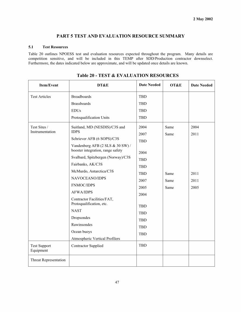
2 May 2002
47
PART 5 TEST AND EVALUATION RESOURCE SUMMARY
5.1 Test Resources
Table 20 outlines NPOESS test and evaluation resources expected throughout the program. Many details are competition sensitive, and will be included in this TEMP after SDD/Production contractor downselect. Furthermore, the dates indicated below are approximate, and will be updated once details are known.
Table 20 - TEST & EVALUATION RESOURCES
Item/Event DT&E Date Needed OT&E Date Needed
Test Articles Breadboards
Brassboards
EDUs
Protoqualification Units
TBD
TBD
TBD
TBD
Test Sites / Instrumentation
Suitland, MD (NESDIS)/C3S and IDPS
Schriever AFB (6 SOPS)/C3S
Vandenberg AFB (2 SLS & 30 SW) / booster integration, range safety
Svalbard, Spitzbergen (Norway)/C3S
Fairbanks, AK/C3S
McMurdo, Antarctica/C3S
NAVOCEANO/IDPS
FNMOC/IDPS
AFWA/IDPS
Contractor Facilities/FAT, Protoqualification, etc.
NAST
Dropsondes
Rawinsondes
Ocean buoys
Atmospheric Vertical Profilers
2004
2007
TBD
2004
TBD
TBD
TBD
2007
2005
2004
TBD
TBD
TBD
TBD
TBD
Same
Same
Same
Same
Same
2004
2011
2011
2011
2005
Test Support Equipment
Contractor Supplied TBD
Threat Representation

2 May 2002
48
Test Targets and Expendables
Operational Test Force Support
TBD for DT/OT opportunities (including interoperability testing)
Simulations, Models, and Test Beds
FVS (1), NPP
FVS (3), NPOESS
IWPTB
WPTBs (various locations)
ARTS (CMIS)
Code V (OMPS)
OMPS Simulation Code
Others
2004
TBD
Throughout
Sensor Development Sensor Development Sensor Development Sensor Development TBD
Special Requirements TBD
Manpower Requirements
Contractor provided
Early Orbit Testing – IPO provided at MMC
Operational personnel at Centrals
Others
TBD
TBD
TBD
TBD
OTAs 2011
Training Requirements Contractor supplied
Early Orbit Testing – IPO provided
Others TBD
TBD
TBD
TBD
OTAs 2011
T&E Funding Requirements
See 5.3 below
5.2 Test Support Equipment
A significant amount of test support equipment will be needed to test the NPOESS Space, C3 and IDP segments. A majority of this equipment will be designed, fabricated and maintained by the prime contractor. Any specific test support equipment that is provided by the USG for the contractors’ use will be determined during Pre-SDD/Production activities.

2 May 2002
49
5.3 T&E Funding Requirements
Approximately $96 million has been set aside for testing activities through IOC, equally split between DoD and DOC (see Table 21). The totals may not add correctly due to rounding. This figure does not include NPP-specific testing activities, which do not support NPOESS activities and objectives. These activities are funded by NASA.
Table 21 - NPOESS TEST & EVALUATION FUNDING
FY03 FY04 FY05 FY06 FY07 FY08 FY09 FY10 FY11 FY12 TOTAL
DOC 1.1 2.25 6.25 7.25 6.1 6.8 7.6 5.3 5.0 0.5 48.1
DoD 1.1 2.25 6.25 7.25 6.1 6.8 7.6 5.3 5.0 0.5 48.1
2.2 4.5 12.5 14.5 12.2 13.6 15.2 10.6 10.0 1.0 96.2
NOTE: Units are in millions of dollars
5.4 Manpower and Training
The contractor will provide manpower and training for DT&E. Support for formal DT&E acceptance testing is TBD. Support for OT&E will be provided by the Tri-Agency OTAs, with exact numbers TBD. The contractor may be required, during the OT&E phase, to assist the OTAs and provide manpower/training to support OTA test procedures.
The NPOESS prime contractor will provide manpower to perform early-orbit testing at Suitland MMC, supported by the Government. NESDIS, AFWA, AFOTEC, FNMOC, NAVOCEANO and others will provide support as required for testing.

2 May 2002
50
ANNEX A BIBLIOGRAPHY
1. NSTC-2 5 May 94
Presidential Decision Directive
2. DMSP/NPOESS STAR, Secret, NAIC-1571-0110-96 Apr 01
DMSP/NPOESS System Threat Assessment Report (STAR)
3. IORD II 10 Dec 01
Integrated Operational Requirements Document for NPOESS
4. DoDR 5000.2-R 1 Jun 01
DoD Instruction for Mandatory Procedures for Major Defense Acquisition Programs
5.
NPOESS SCG 20 Aug 01
NPOESS Security Classification Guide
6.
PMD 2384 (1) 31 Jan 97
NPOESS Program Management Directive
7. MIL-STD 1540C 15 Sep 94
Test Requirements for Booster, Upper-Stage, and Space Vehicles
8. IEEE/EIA 12207 1996
Standard for Information Technology Software Life Cycle Processes
9. Title 10, USC, Section 2366, Dec 89
Major Systems and Munitions Programs: Survivability and Lethality Testing Required Before Full-Scale Production
10. Title 10, USC, Section 2399(b) (1), Dec 89
Operational Test and Evaluation
11. Title 42, USC, Section 4321, Chapter 55, 1969
National Environmental Policy Act
12. NPOESS SAMP Jan 02
NPOESS Single Acquisition Management Plan
13. NPOESS MOA 26 May 95
Tri-Agency Memorandum of Agreement
14. NPOESS TPWG/CTF Charter 9 Jul 01
NPOESS Test Planning Working Group and Combined Test Force Charter
15. NPP PVP 6 Apr 01
NPOESS Preparatory Project Performance Verification Plan
16. NPP SI&T Plan 31 Oct 01
NPOESS Preparatory Project System Integration and Test Plan
17. DoD JTA Ver 4.0 2 Apr 01
Department of Defense Joint Technical Architecture
18. NPOESS TRD Ver 7 24 Jan 02
Technical Requirements Document
19 Field Terminal, MOA 20 Sep 01.
Field Terminal, Interoperability and Funding Memorandum for Agreement (Attachment P)

2 May 2002
51
ANNEX B ACRONYMS
ACAT Acquisition Category
ADA Associate Director for Acquisition
ADCS Advanced Data Collection System
ADS Archive and Distribution Segment
ADO Associate Director for Operations
ADTT Associate Director for Technology Transition
AF Air Force
AFAE Air Force Acquisition Executive
AFB Air Force Base
AFOTEC Air Force Operational Test and Evaluation Center
AFI Air Force Instruction
AFSCN Air Force Satellite Control Network
AFSPC Air Force Space Command
AFWA Air Force Weather Agency
AGE Aerospace Ground Equipment
AIRS Atmospheric Infrared Sounder
ALT Radar Altimeter
AMSU/MHS Advanced Microwave Sounding Unit/Microwave Humidity Sounder
APS Aerosol Polarimetry Sensor
ARTS Automated Remote Tracking Station
ASD/C3I Assistant Secretary of Defense / Command, Control, Communications and Intelligence
A&T Acquisition and Technology
ATEC Army Test and Evaluation Command
ATMS Advanced Technology Microwave Sounder
AVHRR Advanced Very High Resolution Radiometer
C3 Command, Control and Communications
C3S Command, Control and Communications Segment
CARD Cost Analysis Requirements Document
CDA Command and Data Acquisition
CDR Critical Design Review
CERES Clouds and Earth's Radiant Energy System
CFI Call For Improvement

2 May 2002
52
CI Configuration Item
CMIS Conical Microwave Imager Sounder
CNES Centre National D’Etudes Spatiales
COBRA Cost, Operational Benefit and Requirements Analysis
COI Critical Operational Issue
CrIS Cross-Track Infrared Sounder
CY Calendar Year
DMSP Defense Meteorological Satellite Program
DOC Department of Commerce
DoD Department of Defense
DOT&E Director, Operational Test and Evaluation
DT&E Developmental Test and Evaluation
DT/OT Developmental Testing and Operational Testing
DTSE&E Director, Test, Systems Engineering and Evaluation
EARD Evolutionary Algorithm Research and Development
EDR Environmental Data Record
EDU Engineering Development Unit (Mockup)
EELV Evolved Expendable Launch Vehicle
ELT Emergency Locator Transmitter
EMD Engineering and Manufacturing Development
EMI/EMC Electromagnetic Interference / Electromagnetic Compatibility EOA Early Operational Assessment
EOS Earth Orbiting Satellite
EPIRB Emergency Position-Indicating Radio Beacon
ERBS Earth Radiation Budget Sensor
ESA European Space Agency
EUMETSAT European Meteorological Satellite
FNMOC Fleet Numerical Meteorology and Oceanography Center
FOC Full Operational Capability
FOT&E Follow-on Operational Test and Evaluation
FQT Formal Qualification Test
FVS Flight Vehicle Simulator
FY Fiscal Year
GFE Government Furnished Equipment
GFP Government Furnished Property

2 May 2002
53
GLONASS GLObal NAvigation Satellite System
GOES Geostationary Operational Environmental Satellite
GOME Global Ozone Monitoring Experiment
GPSOS Global Positioning System Occultation Sensor
GRAS Global Navigation Satellite System (GNSS) Receiver for Atmospheric Sounder
GSE Ground Support Equipment
HRPT High Resolution Picture Transmission
HWIL Hardware-in-the-Loop
IA&T Integration, Assembly & Test
IASI/HIRS Infrared Atmospheric Sounding Interferometer/High Resolution Infrared Radiation Sounder
IDP Interface Data Processor
IDPS Interface Data Processor Segment
IEEE Institute for Electrical and Electronics Engineers
IER Information Exchange Requirement
ILS Integrated Logistics Support
IMP Integrated Master Plan
IMS Integrated Master Schedule
IOC Initial Operational Capability
IORD Integrated Operational Requirements Document
IPO Integrated Program Office
IR Infrared
IWPTB Integrated Weather Product Test Best
JTA Joint Technical Architecture
LRIP Low Rate Initial Production
LRPT Low Resolution Picture Transmission
LSP Launch Service Provider
LSS Launch Support Segment
METOP Meteorological Operational satellite (of the EUMETSAT Polar System)
MMC Mission Management Center
MOA Memorandum of Agreement
MOE Measure of Effectiveness
MOP Measure of Performance
MS Milestone
MODIS Moderate Resolution Imaging Spectroradiometer
MOT&E Multi-Departmental Operational Test & Evaluation

2 May 2002
54
MTPE Mission To Planet Earth
NASA National Aeronautics & Space Administration
NCEP National Centers for Environmental Prediction
NESDIS National Environmental Satellite, Data and Information Service
NOAA National Oceanic and Atmospheric Administration
NPOESS National Polar-orbiting Operational Environmental Satellite System
NPP NPOESS Preparatory Project
OA Operational Assessment
OAT Operational Algorithm Team
OBP On Board Processing
OMPS Ozone Mapping and Profiler Suite
OOAT Overarching Operational Algorithm Team
OPR Office of Primary Responsibility
OPTEVFOR Operational Test and Evaluation Force (Navy)
ORD Operational Requirements Document
OSD Office of the Secretary of Defense
OTA Operational Test Agency
OT&E Operational Test and Evaluation
PCA Physical Configuration Audit
PDD Presidential Decision Directive
PDR Preliminary Design Review
PDRR Program Definition and Risk Reduction
PE Program Element
PESHE Programmatic Environmental, Safety and Health Evaluation
PH Phase
PLB Personal Locator Beacon
POE Program Office Estimate
POES Polar Operational Environmental Satellite
PQT Preliminary Qualification Test
PVP Performance Verification Plan
RDR Raw Data Record
RDS Real-time Data Smoothed
RPIE Real Property Installed Equipment
RTS Real Time Simulator
S/C Spacecraft
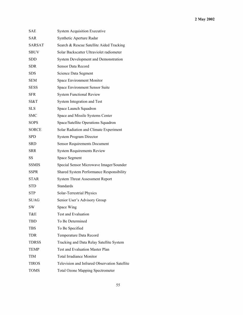
2 May 2002
55
SAE System Acquisition Executive
SAR Synthetic Aperture Radar
SARSAT Search & Rescue Satellite Aided Tracking
SBUV Solar Backscatter Ultraviolet radiometer
SDD System Development and Demonstration
SDR Sensor Data Record
SDS Science Data Segment
SEM Space Environment Monitor
SESS Space Environment Sensor Suite
SFR System Functional Review
SI&T System Integration and Test
SLS Space Launch Squadron
SMC Space and Missile Systems Center
SOPS Space/Satellite Operations Squadron
SORCE Solar Radiation and Climate Experiment
SPD System Program Director
SRD Sensor Requirements Document
SRR System Requirements Review
SS Space Segment
SSMIS Special Sensor Microwave Imager/Sounder
SSPR Shared System Performance Responsibility
STAR System Threat Assessment Report
STD Standards
STP Solar-Terrestrial Physics
SUAG Senior User’s Advisory Group
SW Space Wing
T&E Test and Evaluation
TBD To Be Determined
TBS To Be Specified
TDR Temperature Data Record
TDRSS Tracking and Data Relay Satellite System
TEMP Test and Evaluation Master Plan
TIM Total Irradiance Monitor
TIROS Television and Infrared Observation Satellite
TOMS Total Ozone Mapping Spectrometer

2 May 2002
56
TOPEX Topography Experiment
TPWG Test Planning Working Group
TRD Technical Requirements Document
TRMM Tropical Rainfall Measuring Mission
TSIS Total Solar Irradiance Sensor
USA United States Army
USAF United States Air Force
USB Unified S-Band
USC United States Code
USCG United States Coast Guard
USD Under Secretary of Defense
USG United States Government
USMC United States Marine Corps
USN United States Navy
V&V Verification and Validation
VIIRS Visible/Infrared Imager Radiometer Suite
WPTB Weather Products Test Bed
WR Western Range
WS Weather Squadron

2 May 2002
57
ANNEX C POINTS OF CONTACT
ROLE ORG PHONE
TEMP Coordinator Benji Spencer
IPO
301-427-2128
Principal Deputy System Program Director Col Frank Hinnant
IPO 301-427-2070
System Program Director Mr John Cunningham
IPO
301-427-2070
Joint Interoperability Test Command Maj Quintanilla
JITC/JTEA
520-538-5138
AFOTEC Maj Stuart Kurkowski
Det 4 AFOTEC/FE 719-556-5883
HQ AFSPC Maj Keith Forman
AFSPC/DRFE 719-554-9774
NOAA/NESDIS
NESDIS 301-457-5180
Program Element Monitor (PEM) Maj Steven Kravchin
SAF/USA 703-588-7357
Air Force Test and Evaluation Maj David Wilkinson
AF/TEP
703-697-0322
Director, Developmental Test & Evaluation Lt Col Mark Garlow
OUSD(AT&L)/S&TS/DT&E
703-695-7246
Director, Program Analysis & Integration
ASD/C3I
Director, Operational Test and Evaluation Col Jim Mackin
OSD/DOT&E 703-681-1440 x.118

2 May 2002
58
ANNEX D DEFINITIONS
Acceptance Test—Tests that demonstrate that a specified article or lot of articles meets specification requirements and quality control assurance against workmanship or material deficiencies. Testing will stress screen the hardware to precipitate latent parts and workmanship defects to failure, however, testing should not create conditions which exceed design safety margins or cause unrealistic modes of failure.
Brassboard Configuration—An experimental device (or group of devices) used to determine feasibility and to develop technical and operational data. It normally will be a model sufficiently hardened for use outside of laboratory environments to demonstrate the technical and operational principles of immediate interest. It may resemble the end item, but is not intended for use as the end item.
Breadboard Configuration—An experimental device (or group of devices) used to determine feasibility and to develop technical data. It normally will be configured only for laboratory use to demonstrate the technical principles of immediate interest. It may not resemble the end item and is not intended for use as the projected end item.
Combined Testing—Simultaneous testing conducted by the development and operational testers when cost, schedule, or test item availability dictates that they must share test facilities, resources, and data.
Compatibility—Capability of two or more items or components of equipment to exist or function in the same system or environment without mutual interference.
Critical Operational Issue—A key issue that testers must examine in operational test and evaluation to determine the system’s capability to perform its mission. Testers normally phrase a critical operational issue as a question to be answered in evaluating a system’s operational effectiveness or suitability.
Developmental Test and Evaluation—Testing and evaluation conducted to evaluate design approaches, validate analytical models, quantify contract technical performance and manufacturing quality, measure progress in system engineering design and development, minimize design risks, predict integrated system operational performance in the intended environment, and identify system problems to allow for early and timely resolution or correction. DT&E includes contractor testing.
Early Operational Assessment—An operational assessment conducted before or at Milestone B.
Hardware-in-the-Loop—Testing that involves system or subsystem hardware in an open or closed-loop mode against high fidelity targets and threat simulations. It allows testers to test developmental and production systems under controllable, repeatable, non-destructive conditions.
Integrated Program Office—The organization comprised of technical, administrative and business management personnel assigned full-time to the system program director. The office may be augmented with additional personnel from participating organizations.
Low Rate Initial Production—The production of a system in limited quantity to be used to verify production capability and to provide test resources needed to conduct inter-operability or operational testing.
Measure of Effectiveness—A measure of a system’s task accomplishment. Testers should define MOEs to measure operational capabilities in terms of engagement or battle outcome. Testers should also develop MOEs to a level of specificity such that they can assess a system’s effectiveness using the same criteria as for the cost and operational effectiveness analysis.
Measure of Performance—A qualitative or quantitative measure of a system’s capabilities or characteristics. It indicates the degree to which that capability or characteristic performs or meets a requirement under specified conditions. MOPs such as weight and speed should relate to the measures of effectiveness (MOEs) so that testers can relate the effect of a change in the MOP to a change in the MOE.

2 May 2002
59
Multi-Service Operational Test and Evaluation—All operational test and evaluation conducted on production or production representative articles to help decide whether to proceed beyond low-rate initial production. MOT&E is conducted to estimate how well the system attains operational effectiveness and suitability.
Operational Assessment—An independent appraisal of the status of the operational effectiveness and suitability aspects of the acquisition or modification program made by the operational test agency. The focus of an OA is on significant trends noted in development efforts, programmatic voids, areas of risk, adequacy of requirements, and the ability of the program to support adequate operational testing.
Operational Effectiveness—The overall degree of mission accomplishment of a system when used by representative personnel in the environment planned or expected for operational employment of the system considering organization, doctrine, tactics, survivability, vulnerability, and threat.
Operational Requirement—An established need justifying the timely allocation of resources to achieve a capability to accomplish approved objectives, missions, or tasks.
Operational Suitability—The degree to which a system can be placed satisfactorily in field use, considering availability, compatibility, transportability, interpretability, reliability, wartime usage rates, maintainability, safety, human factors, manpower supportability, logistics supportability, natural environmental effects and impacts, documentation, and training requirements.
Operational Test Agency—The agency designated by the program management directive, or other appropriate directive, as responsible for managing and conducting the independent OT&E of a system.
Operational Test and Evaluation—Testing and evaluation (divided into initial operational test and evaluation and follow-on test and evaluation, and generally associated with the first major production decision) conducted in as realistic an environment as possible to estimate the prospective system’s utility, operational effectiveness, and operational suitability.
Performance Objective—The performance parameter value beyond the minimum acceptable operational requirement that could have a beneficial impact on the achieved operational capability.
Performance Threshold—The performance parameter value that meets the minimum level of a system performance that will satisfy the validated mission need. Also known as the minimum acceptable operational requirement.
Preproduction Qualification Test (Preliminary Qual Test)—The formal contractual tests that ensure design integrity over the specified operational and environmental range. These tests usually use prototype or preproduction hardware fabricated to the proposed production design specifications and drawings. Such tests include contractual reliability and maintainability demonstrations tests required prior to production release.
Production Qualification Test—A technical test conducted post MS B to ensure the effectiveness of the manufacturing process, equipment and procedures. This testing also serves the purpose of providing data for the independent evaluation required for material release so that the evaluator can address the adequacy of the materiel with respect to the stated requirements. These tests are conducted on a number of samples taken at random from the first production lot, and are repeated if the process or design is changed significantly, and when a second or alternative source is brought on line. Program funding category—Procurement
Protoflight—A protoflight unit for this program is one that was tested to protoqualification test levels. The unit is usually the first unit built.
Protoqualification—A test strategy in which qualification and acceptance tests are combined. The unit is tested to levels beyond what is expected in flight and beyond minimum workmanship levels, but test levels and duration are less than qualification levels and duration.
Prototype—An original or model on which a later item is formed or based. Early prototypes may be built during Demonstration/Validation/SDD/Production phase and tested prior to a production decision.

2 May 2002
60
Qualification Test—Simulates defined operational environmental conditions with a predetermined safety factor, the results indicating whether a given design can perform its function within the simulated operational environment of a system.
Simulation—A simulation is a method for implementing a model. It is the process of conducting experiments with a model for the purpose of understanding the behavior of the system modeled under selected conditions or of evaluating various strategies for the operation of the system within the limits imposed by developmental or operational criteria. Simulation may include the use of analog or digital devices, laboratory models, or "testbed" sites. Simulations are usually programmed for solution on a computer; however, in the broadest sense, military exercises and war games are also simulations.
Supportability—The degree to which a system design characteristics and planned logistics resources, including manpower, meet system readiness and utilization requirements.
System Threat Assessment Report—The STAR is the basic authoritative threat assessment, tailored for and focused on, a particular acquisition program. It describes the threat to be countered and the projected threat environment. The threat information is based on Defense Intelligence Agency (DIA) validated documents.
Test Event—An activity during conduct of a test trial that requires a response by the system and/or personnel under test.
Test Facility—The type of a test resource (e.g. integration laboratory, open-air range, etc.) used to support the test.
Test Objective—The specific performance or technical parameters to be measured during the test to evaluate system performance, system operational effectiveness, or system suitability.
Test Plan—A document that incorporates details of testing location, resources, methodology, user-accepted criteria, funding, personnel, and schedules in sufficient detail for the day to day conduct of developmental or operational test activity. The test plan is the responsibility of the developmental/operational test agency.
Validation—An activity that ensures that a set of technical requirements is consistent and complete with respect to parent requirements. An activity that ensures that an end product stakeholder’s true needs and expectations are met. For example, in modeling and simulation, validation is the process of ensuring that the simulation is a reasonable abstraction of the real world it is intended to represent.
Verification—An activity that ensures that the selected design solution satisfies the detailed technical requirements.

2 May 2002
61
ATTACHMENT A VISIBLE/INFRARED IMAGER/RADIOMETER SUITE (VIIRS)
The VIIRS is the next generation visible and infrared imaging radiometer and is a single instrument with multiple focal planes. The VIIRS will meet the requirements for the key Imagery and Sea Surface Temperature EDRs, as well as 21 other EDRs. See Table 6 for a detailed breakdown of the EDRs produced by VIIRS. Two contracts were awarded in the first of two acquisition phases. The first phase was to study, in detail, the requirements which the instrument must satisfy, identify areas of technical risk, start risk mitigation activities and perform a detailed series of trade studies on the best approach to satisfying the requirements. A preliminary design for an instrument was then developed by each contractor, including conducting a formal PDR. Both contractors completed this phase on 30 June 2000. Following completion of the PDRs, the government issued a Call for Improvement (CFI) to assess each contractor’s concept. Based upon the results of the CFI, the government selected one contractor, Raytheon of Santa Barbara, California, to carry their concept into full-scale development and fabrication. This procurement strategy has been selected as affording the best opportunity for developing an instrument capable of satisfying all EDR requirements, taking actions early in the program to minimize technical risk, and obtaining the best instrument design possible.
VIIRS Mission
The mission of the VIIRS is to provide high quality imagery and radiometric data within the visible and infrared spectral regions to support worldwide DoD and civilian operations and high-priority programs.
VIIRS Description
The VIIRS consists of an instrument designed to measure scene radiance in spectral bands within the visible and thermal infrared range (from 0.3 to 14 microns, approximately). The contractor has determined the sensor characteristics and performance requirements needed to satisfy a specified subset of the NPOESS EDRs.
The VIIRS instrument will perform the following functions: scene radiance measurement; on-orbit calibration; acquisition of sensor health, status, and thermal data; generation of LDR and HDR data packets; reception of command and control data; accommodate the uplinking of new flight software packages; assume the physical configuration; and gather the data required for each functional mode. Additionally, VIIRS should perform the following functions, if needed to meet requirements, based on the contractor’s design: on-orbit monitoring of calibration sources and instrument response changes; and gain adjustments to meet dynamic range requirements. As a minimum, VIIRS will implement the following modes: off; outgassing; activation; early orbit checkout; mission; autonomous operations; safe hold; survival modes; and one or more calibration modes, if needed. The VIIRS is separately commandable into any of the above modes, regardless of the operational mode of any other instrument in the suite or on the spacecraft.
Algorithms
The NPOESS prime contractor will adopt or adapt existing algorithms or develop new algorithms for all primary EDRs, as well as all intermediate level data products, such as SDRs and data quality flags. Adopting an algorithm means using an existing algorithm without change. Adapting an algorithm means using an existing algorithm with some modification, such as different values of coefficients, inclusion of higher order corrections or fusion of additional data sources. Algorithms need not be provided for data products that are generated by other sensor suites and utilized as inputs to the algorithms for VIIRS primary EDRs.
The generation and delivery of operational EDRs is the responsibility of the prime contractor, not the VIIRS contractor. This includes the conversion of the sensor vendor’s science code to operational code. As a minimum, the VIIRS design and algorithms allow the EDR requirements to be satisfied at the threshold level. Furthermore, the prime contractor and each Central will have an algorithm development capability for modifying or developing new algorithms. Each Central is also equipped with a limited set of IDPS resources on which to independently develop, experiment, refine, and run local algorithms. Additionally, the OATs, working closely with the contractors, will provide insights into improvements that reduce risk, improve efficiency and improve the end product.

2 May 2002
62
ATTACHMENT B CONICAL MICROWAVE IMAGER SOUNDER (CMIS)
The CMIS is the next-generation conical scanning microwave imager sounder, and will incorporate the lessons learned from two previous generations of DoD instruments: the Special Sensor Microwave Imager (SSMI) and Special Sensor Microwave Imager/Sounder (SSMI/S). The CMIS will meet the requirements for the key Atmospheric Vertical Temperature Profile, Global Sea Surface Wind (Speed), and Soil Moisture EDRs, as well as 16 other EDRs. See Table 6 for a detailed breakdown of the EDRs produced by CMIS. CMIS will provide improved capabilities of measurement accuracy through the inclusion of additional measurement channels, increased ground measurement resolution (as a result of a larger antenna), sensing in all weather conditions (e.g., overcast or cloudy skies), and new measurement capabilities such as sea surface wind direction and soil moisture. CMIS will also incorporate recent technology improvements such as microwave integrated circuits. The IPO will monitor developments on the NASA Mission to Planet Earth, Advanced Microwave Scanning Radiometer (AMSR), the ATMS sensor and Seawinds sensors as well as the Navy’s proposed WindSat for synergistic opportunities.
CMIS Mission
The mission of the CMIS is to provide microwave imagery and brightness temperature within the microwave spectral regions to support worldwide DoD and civilian operations and high-priority programs.
CMIS Description
The CMIS consists of an instrument designed to measure brightness temperatures in multiple microwave spectral bands. The contractor will determine the sensor characteristics, performance requirements and calibration/validation needed to satisfy a specified subset of the NPOESS EDRs.
Each CMIS instrument will perform the following functions: scene radiance measurement; on-orbit calibration; acquisition of sensor health, status, and thermal data; generation of LDR and HDR data packets; reception of command and control data; accommodate the uplinking of new flight software packages; assume the physical configuration; and gather the data required for each functional mode. Each CMIS instrument should perform the following functions, if needed to meet requirements, based on the contractor’s design: on-orbit monitoring of calibration sources and instrument response changes; and gain adjustments to meet dynamic range requirements. As a minimum, the CMIS instrument will implement the following modes: off; outgassing; activation; early orbit checkout; mission; autonomous operations; safe hold; survival; and one or more calibration modes, if needed. Each CMIS will be separately commandable into any of the above modes, regardless of the operational mode of any other instrument in the suite or on the spacecraft.
Algorithms
The NPOESS prime contractor will adopt or adapt existing algorithms or develop new algorithms for all primary EDRs, as well as all intermediate level data products, such as SDRs and data quality flags. Adopting an algorithm means using an existing algorithm without change. Adapting an algorithm means using an existing algorithm with some modification, such as different values of coefficients, inclusion of higher order corrections or fusion of additional data sources. Algorithms need not be provided for data products that are generated by other sensor suites and utilized as inputs to the algorithms for CMIS primary EDRs.
The generation and delivery of operational EDRs is the responsibility of the prime contractor, not the CMIS contractor. This includes the conversion of the sensor vendor’s science code to operational code. As a minimum, the CMIS design and algorithms allow the EDR requirements to be satisfied at the threshold level. Furthermore, the prime contractor and each Central will have an algorithm development capability for modifying or developing new algorithms. Each Central is also equipped with a limited set of IDPS resources on which to independently develop, experiment, refine, and run local algorithms. Additionally, the OATs, working closely with the contractors, will provide insights into improvements that reduce risk, improve efficiency and improve the end product.

2 May 2002
63
ATTACHMENT C CROSS-TRACK INFRARED SOUNDER (CrIS)
The CrIS is a next generation IR sounder that is one of the two sensors that make up the Cross-Track Infrared Microwave Sounder Suite (CrIMSS). The other sensor is the NASA-procured ATMS. The CrIMSS, along with the CMIS, is used to meet the key Atmospheric Vertical Temperature Profile and Atmospheric Vertical Moisture Profile EDRs, as well as one other EDR. See Table 6 for a detailed breakdown of the EDRs produced by CrIS. CrIMSS is a is a secondary contributor to another 9 EDRs, and has the potential to address 14 other EDR requirements. The IPO’s strategy is to focus sensor development efforts on the CrIMSS sensor suite and to monitor other IR sounder developments like the European instrument, IASI and NASA AIRS. The CrIS is entering into the detailed design and fabrication stage including the heart of the design, which is the Michelson Interferometer. The CrIS design will provide an alternate technology path to the achievement of a high spatial/high spectral resolution operational IR sounding instrument. Additionally, CrIS will fly on the NASA NPOESS Preparatory Project (NPP) spacecraft to provide further risk reduction and lessons learned that allow for any required modifications to support NPOESS first launch readiness.
CrIS Mission
The mission of the CrIS is to provide an advanced cross-track sounding capability and to provide data required to satisfy NPOESS requirements for temperature and moisture sounding profiles, as well as other EDRs to support worldwide DoD and civilian operations and high-priority programs.
CrIS Description
The CrIS will be a passive Michelson interferometer that measures the radiation data, to be incorporated with other data gathered by the NPOESS, to satisfy NPOESS EDR requirements. The contractor will determine the sensor characteristics and performance requirements needed to satisfy a specified subset of the NPOESS EDRs.
Each CrIS instrument will measure emission from the earth in the infrared spectrum, provide calibration for these data and provide data for the NOAA and DoD sounding measurement missions. As a minimum, the CrIS instrument will implement the following modes: off; outgassing; activation; early orbit checkout; mission; autonomous operations; safe hold; survival; and one or more calibration modes, if needed. Each CrIS will be separately commandable into any of the above modes, regardless of the operational mode of any other instrument in the suite or on the spacecraft.
Algorithms
The NPOESS prime contractor will adopt or adapt existing algorithms or develop new algorithms for all primary EDRs, as well as all intermediate level data products, such as SDRs and data quality flags. Adopting an algorithm means using an existing algorithm without change. Adapting an algorithm means using an existing algorithm with some modification, such as different values of coefficients, inclusion of higher order corrections or fusion of additional data sources. Algorithms need not be provided for data products that are generated by other sensor suites and utilized as inputs to the algorithms for CrIS primary EDRs.
The generation and delivery of operational EDRs is the responsibility of the prime contractor, not the CrIS contractor. This includes the conversion of the sensor vendor’s science code to operational code. In addition, algorithm definition work will include the incorporation of existing or modified USG algorithms (such as those developed under the EOS program) in order to leverage, as much as practicable, other work being done in the sounding retrieval arena. As a minimum, the CrIS design and algorithms allow the EDR requirements to be satisfied at the threshold level. Furthermore, the prime contractor and each Central will have an algorithm development capability for modifying or developing new algorithms. Each Central is also equipped with a limited set of IDPS resources on which to independently develop, experiment, refine, and run local algorithms. Additionally, the OATs, working closely with the contractors, will provide insights into improvements that reduce risk, improve efficiency and improve the end product.

2 May 2002
64
ATTACHMENT D ADVANCED TECHNOLOGY MICROWAVE SOUNDER (ATMS)
The first ATMS flight unit is procured by NASA (with the subsequent flight units being the responsibility of the NPOESS prime contractor) and is one of the two sensors that make up the Cross-Track Infrared Microwave Sounder Suite (CrIMSS). The other sensor is the CrIS. The ATMS has sensor performance requirements similar to that projected for the Advanced Microwave Sounding Unit (AMSU)-A1, AMSU-A2 and AMSU-B microwave sounding units. The CrIMSS, along with the CMIS, is used to meet the key Atmospheric Vertical Temperature Profile and Atmospheric Vertical Moisture Profile EDRs, as well as one other EDR. See Table 6 for a detailed breakdown of the EDRs produced by ATMS. CrIMSS is a secondary contributor to another 9 EDRs, and has the potential to address 14 other EDR requirements. Additionally, CrIMSS will fly on the NASA NPOESS Preparatory Project (NPP) spacecraft to provide further risk reduction and lessons learned that allow for any required modifications to support NPOESS first launch readiness.
ATMS Mission
The mission of the ATMS is to provide the microwave portion of the Atmospheric Vertical Temperature Profile and Atmospheric Vertical Moisture Profile EDRs, as well as other EDRs to support worldwide DoD and civilian operations and high-priority programs.
ATMS Description
The ATMS collects specialized data to permit the calculation of atmospheric temperature and water vapor profiles. The sensor measures the Earth’s microwave radiation in 22 to 31 channels from 23.8 to 183.3 GHz to determine, along with the CrIS data, the vertical distribution of temperature, moisture and pressure in the atmosphere.
Algorithms
The NPOESS prime contractor will adopt or adapt existing algorithms or develop new algorithms for all primary EDRs, as well as all intermediate level data products, such as SDRs and data quality flags. Adopting an algorithm means using an existing algorithm without change. Adapting an algorithm means using an existing algorithm with some modification, such as different values of coefficients, inclusion of higher order corrections or fusion of additional data sources. Algorithms need not be provided for data products that are generated by other sensor suites and utilized as inputs to the algorithms for ATMS primary EDRs.
The generation and delivery of operational EDRs is the responsibility of the prime contractor, not the ATMS contractor. This includes the conversion of the sensor vendor’s science code to operational code. In addition, algorithm definition work will include the incorporation of existing or modified USG algorithms (such as those developed under the EOS program) in order to leverage, as much as practicable, other work being done in the sounding retrieval arena. As a minimum, the ATMS design and algorithms allow the EDR requirements to be satisfied at the threshold level. Furthermore, the prime contractor and each Central will have an algorithm development capability for modifying or developing new algorithms. Each Central is also equipped with a limited set of IDPS resources on which to independently develop, experiment, refine, and run local algorithms. Additionally, the OATs, working closely with the contractors, will provide insights into improvements that reduce risk, improve efficiency and improve the end product.
2 May 2002
65
ATTACHMENT E OZONE MAPPING AND PROFILER SUITE (OMPS)
The OMPS monitors ozone from space and will incorporate the lessons learned from two previous generations of instruments: the Solar Backscatter Ultraviolet radiometer (SBUV)/2 and Total Ozone Mapping Spectrometer (TOMS). These two sensors produce daily global data records that will continue with OMPS, but with higher fidelity. Currently, the SBUV/2 produces nadir profile data records and the TOMS produces total column data records. The OMPS is used to meet one NPOESS EDR and is a secondary contributor to another 3 EDRs. See Table 6 for a breakdown of the EDR produced by OMPS. Currently, OMPS is scheduled to be delivered in Dec 2004 and may be flown on a yet to be determined flight of opportunity.
OMPS Mission
OMPS will collect total column and vertical profile ozone data and continue the daily global data produced by the current ozone monitoring systems, SBUV/2 and TOMS, but with higher fidelity. The collection of this data contributes to fulfilling the U.S. treaty obligation to monitor the ozone depletion for the Montreal Protocol to ensure no gaps in ozone coverage.
OMPS Description
The OMPS is comprised two sensors -- a nadir sensor and a limb sensor. Both sensors maintain long term data product stability through periodic solar irradiance measurements. In addition, an Interface and Control Electronics (ICE) box and a ground processing and algorithm segment process the data obtained by the sensors to generate geolocated and calibrated radiances and ozone data products.
The nadir sensor uses a wide field-of-view push-broom telescope to feed two separate spectrometers. The nadir total column spectrometer (mapper) measures the scene radiance between 300 to 380 nanometer (nm) with a resolution of 1 nm sampled at 0.42 nm and a 24-hour ground revisit time. Measurements from this spectrometer are used to generate total column ozone data with better than 50 x 50 kilometer (km) resolution at nadir. The nadir profile spectrometer measures between 250 and 310 nm with the same spectral sampling, in a single ground pixel of 250 x 250 km.
The limb sensor measures the along-track limb scattered solar radiance with 1-km vertical sampling in the spectral range of 290 to 1000 nm. Three vertical slits sample the limb at 250-km cross-track intervals to provide for better than 7-day ground revisit times. The three slits are imaged onto a single charge-coupled device (CCD) (identical to both nadir CCDs).
Algorithms
The NPOESS prime contractor will adopt or adapt existing algorithms or develop new algorithms for all primary EDRs, as well as all intermediate level data products, such as SDRs and data quality flags. Adopting an algorithm means using an existing algorithm without change. Adapting an algorithm means using an existing algorithm with some modification, such as different values of coefficients, inclusion of higher order corrections or fusion of additional data sources. Algorithms need not be provided for data products that are generated by other sensor suites and utilized as inputs to the algorithms for OMPS primary EDRs.
The generation and delivery of operational EDRs is the responsibility of the prime contractor, not the OMPS contractor. This includes the conversion of the sensor vendor’s science code to operational code. As a minimum, the OMPS design and algorithms allow the EDR requirements to be satisfied at the threshold level. Furthermore, the prime contractor and each Central will have an algorithm development capability for modifying or developing new algorithms. Each Central is also equipped with a limited set of IDPS resources on which to independently develop, experiment, refine, and run local algorithms. Additionally, the OATs, working closely with the contractors, will provide insights into improvements that reduce risk, improve efficiency and improve the end product.

2 May 2002
66
ATTACHMENT F GPS OCCULTATION SENSOR (GPSOS)
A suite of Global Positioning System (GPS) receivers will be used to receive GPS signals. An on-board processor will determine the atmospheric effects on the signals sent from the GPS constellation. The heritage sensor for GPSOS is the Global Navigation Satellite System (GNSS) Receiver for Atmospheric Sounder (GRAS), which will be flown on METOP. SAAB Ericsson Space, located in Sweden, is building both the GRAS and GPSOS. This will enable an efficient use of lessons learned. The GPSOS is used to meet two NPOESS EDRs. See Table 6 for a detailed breakdown of the EDRs produced by GPSOS. The GPSOS instrument will provide a direct measurement of the ionospheric total electron content (TEC) profiles by conducting 2500 daily GPS and Global Navigation Satellite System (GLONASS) occultation sounding measurements. (GLONASS is a Soviet space-based navigation system comparable to the U.S. GPS.) These ionosphere soundings will be merged with precision GPS ground network data to calculate the overall atmospheric vertical profile for TEC at a sampling density of 500 km X 500 km. This will improve upon current estimates of ionospheric TEC, which are derived by modeling activities using sun spot activity and ionospheric dissociative temperature profiles.
GPSOS Mission
The GPSOS main functions can be listed as: setting and rising occultation measurements of GPS satellites; and real time navigation and LEO precise orbit determination (POD) support measurements, based on overhead GPS signals.
One basic function of the GPSOS suite is to receive RF signals emitted by GPS satellites as they pass through the atmosphere at lower altitudes. The signals will be acquired, tracked and demodulated. Measurements of this kind are referred to as occultation measurements. The signals of the occulting satellites are received through two antennas, one dedicated to the rising occultations and one dedicated to the setting occultations. The demodulation process is supposed to introduce a minimum of distortion to the atmospheric influence on the signal. However, at the same time it has to cope with low signal power levels and wide signal dynamics. This formidable task is accomplished by means of a tracking receiver supported by linear parameter estimation techniques.
The instrument also operates as a navigation receiver. In this context, it receives GPS signals via a third zenith-pointing antenna with wide conical coverage. It acquires and tracks GPS signals and provides the associated observable as part of its measurement data. This data is then transmitted to the ground segment and used to compute the precise spacecraft orbit. This is referred to as precise orbit determination (POD) and is done to support the exploitation of the occultation measurement results. In addition, the instrument computes the position and velocity of the spacecraft. This is referred to as real-time navigation and is used to control its operations. The instrument uses received navigation messages and timing information to monitor the movement of the GPS constellation and autonomously decides which satellites to acquire, track or release and for which purpose (navigation or occultation) they will be used. In summary the GPSOS constitutes a highly embedded system consisting of three independent GPS receiver functions, exercising signal processing and navigation algorithms, controlled by an instrument control unit (ICU).
GPSOS Description
The GPSOS instrument comprises two main functional subsystems, the GPSOS Antenna subsystem and the GPSOS Electronic Subsystem. The GPSOS Antenna Subsystem comprises three antennas, the GPSOS Velocity Antenna (GVA), the GPSOS Zenith Antenna (GZA) and the GPSOS Anti-Velocity Antenna, (GAVA). The GVA and GAVA are Earth-limb looking antennas used for observing rising and setting occultations. The GZA is a wide beam antenna used for observations of overlaying non-occulting GPS satellites. The GPSOS Electronics subsystem comprises functions such as low noise amplification, RF filtering, RF to IF downconversion, analogue to digital conversion, signal processing and command and control interfaces with the spacecraft’s buses. The GPSOS on-board software implements most of the functionality of the GPSOS instrument. They comprise processing functions and functionality to implement the control processing and data handling, and on-board algorithm processing. Algorithm processing includes occultation measurements, acquisition and tracking, spread spectrum signal processing and navigation processing.

2 May 2002
67
Algorithms
The NPOESS prime contractor will adopt or adapt existing algorithms or develop new algorithms for all primary EDRs, as well as all intermediate level data products, such as SDRs and data quality flags. Adopting an algorithm means using an existing algorithm without change. Adapting an algorithm means using an existing algorithm with some modification, such as different values of coefficients, inclusion of higher order corrections or fusion of additional data sources. Algorithms need not be provided for data products that are generated by other sensor suites and utilized as inputs to the algorithms for GPSOS primary EDRs.
The generation and delivery of operational EDRs is the responsibility of the prime contractor, not the GPSOS contractor. This includes the conversion of the sensor vendor’s science code to operational code. As a minimum, the GPSOS design and algorithms allow the EDR requirements to be satisfied at the threshold level. Furthermore, the prime contractor and each Central will have an algorithm development capability for modifying or developing new algorithms. Each Central is also equipped with a limited set of IDPS resources on which to independently develop, experiment, refine, and run local algorithms. Additionally, the OATs, working closely with the contractors, will provide insights into improvements that reduce risk, improve efficiency and improve the end product.

2 May 2002
68
ATTACHMENT G AEROSOL POLARIMETRY SENSOR (APS)
The APS is an IPO-procured instrument and is a direct contributor to four NPOESS EDRs as well as providing input to others. See Table 6 for a detailed breakdown of the EDRs produced by APS. The APS recently began a Concept Exploration phase, which will lead to a follow-on Program Definition and Risk Reduction phase.
APS Mission
To provide enhanced characterization of selected aerosol properties and to characterize properties such as shape, sphericity, refractive index and single-scattering albedo. It will also characterize the effective radius and effective variance of cloud particles.
APS Description
The APS is a polarimetric imager, which uses multiple wavelengths to make multi-angular measurements of the environment. The sensor detects the atmosphere in at least nine bands between 0.4 and 2.4 microns using a multi-angle approach. The sensing is along track, in the nadir looking direction.
Algorithms
The NPOESS prime contractor will adopt or adapt existing algorithms or develop new algorithms for all primary EDRs, as well as all intermediate level data products, such as SDRs and data quality flags. Adopting an algorithm means using an existing algorithm without change. Adapting an algorithm means using an existing algorithm with some modification, such as different values of coefficients, inclusion of higher order corrections or fusion of additional data sources. Algorithms need not be provided for data products that are generated by other sensor suites and utilized as inputs to the algorithms for GPSOS primary EDRs.
The generation and delivery of operational EDRs is the responsibility of the prime contractor, not the GPSOS contractor. This includes the conversion of the sensor vendor’s science code to operational code. In addition, algorithm definition work will include the incorporation of existing or modified USG algorithms in order to leverage, as much as practical, other work being done in the aerosol sensing arena. As a minimum, the GPSOS design and algorithms allow the EDR requirements to be satisfied at the threshold level. Furthermore, the prime contractor and each Central will have an algorithm development capability for modifying or developing new algorithms. Each Central is also equipped with a limited set of IDPS resources on which to independently develop, experiment, refine, and run local algorithms. Additionally, the OATs, working closely with the contractors, will provide insights into improvements that reduce risk, improve efficiency and improve the end product.

2 May 2002
69
ATTACHMENT H ALTIMETRY SENSOR (ALT)
The Altimetry Sensor is a leveraged payload. A leveraged payload is a payload, which has been developed outside of the NPOESS program. In this instance, the payload is leveraged against the altimeter on the joint NASA/CNES Jason-1 mission, which was launched in Dec 2001. The Jason-1 altimeter was derived from the altimeter on the TOPEX/Poseidon mission that measures sea level, wave heights and wind speed. The NPOESS ALT will meet the performance necessary for three NPOESS EDRs. See Table 6 for a detailed breakdown of the EDRs produced by the ALT. The IPO will be monitoring the Jason instrument and science teams.
Altimetry Sensor Mission
The mission of the Altimetry Sensor is to provide high accuracy altimetry data of the ocean. Its data products will support worldwide DoD and civilian operations and high priority programs.
Altimetry Sensor Description
The Altimetry Sensor consists of two instruments. It consists of a dual frequency radar altimeter, plus a tri-frequency microwave radiometer to provide the total water vapor along the path viewed by the altimeter for range corrections.
Each Altimetry Sensor will perform the following functions: sensor measurements; on-orbit calibration; acquisition of sensor health, status, and thermal data; generation of LDR data packets; reception of command and control data; accommodate the uplinking of new flight software packages; assume the physical configuration; and gather the data required for each functional mode. As a minimum, the Altimetry Sensor will implement the following modes: outgassing; activation; early orbit checkout; mission; autonomous operations; safe hold; survival modes; and calibration mode, if needed. Each Altimetry Sensor will be separately commandable into any of the above modes, regardless of the operational mode of any other instrument in the suite or on the spacecraft.
Algorithms
The NPOESS prime contractor will adopt or adapt existing algorithms or develop new algorithms for all primary EDRs, as well as all intermediate level data products, such as SDRs and data quality flags. Adopting an algorithm means using an existing algorithm without change. Adapting an algorithm means using an existing algorithm with some modification, such as different values of coefficients, inclusion of higher order corrections or fusion of additional data sources. Algorithms need not be provided for data products that are generated by other sensor suites and utilized as inputs to the algorithms for the ALT primary EDRs.
The generation and delivery of operational EDRs is the responsibility of the prime contractor, not the ALT contractor. This includes the conversion of the sensor vendor’s science code to operational code. As a minimum, the ALT design and algorithms allow the EDR requirements to be satisfied at the threshold level. Furthermore, the prime contractor and each Central will have an algorithm development capability for modifying or developing new algorithms. Each Central is also equipped with a limited set of IDPS resources on which to independently develop, experiment, refine, and run local algorithms. Additionally, the OATs, working closely with the contractors, will provide insights into improvements that reduce risk, improve efficiency and improve the end product.

2 May 2002
70
ATTACHMENT I EARTH RADIATION BUDGET SENSOR (ERBS)
The ERBS is a leveraged payload. A leveraged payload is a payload developed outside of the NPOESS program. In this instance, the payload is leveraged against the Cloud and the Earth’s Radiant Energy System (CERES) which has flown on the EOS and TRMM NASA missions. CERES products include both solar-reflected and Earth-emitted radiation from the top of the atmosphere to the Earth's surface. The ERBS is the next-generation CERES radiometer and meets the performance necessary for four NPOESS EDRs. See Table 6 for a detailed breakdown of the EDRs produced by ERBS. The IPO will be monitoring the CERES instrument and science teams.
ERBS Mission
The mission of the ERBS is to provide high quality radiometric data of the earth’s radiation budget and atmospheric radiation from the top of the atmosphere to the surface of the earth. Its data products will support worldwide DoD and civilian operations and high priority programs.
ERBS Description
The ERBS consists of a 3-channel scanning electrical substitution radiometer operating in the range of 0.3microns to more than 100 microns, 0.3 microns to 5 microns, and 8 microns to 12 microns.
Each ERBS instrument will perform the following functions: scene radiance measurement; on-orbit calibration; acquisition of sensor health, status, and thermal data; generation of LDR data packets; reception of command and control data; accommodate the uplinking of new flight software packages; assume the physical configuration; and gather the data required for each functional mode. As a minimum, the ERBS will implement the following modes: off; outgassing; activation; early orbit checkout; mission; autonomous operations; safe hold; survival modes; and calibration mode, if needed. Each ERBS will be separately commandable into any of the above modes, regardless of the operational mode of any other instrument in the suite or on the spacecraft.
Algorithms
The NPOESS prime contractor will adopt or adapt existing algorithms or develop new algorithms for all primary EDRs, as well as all intermediate level data products, such as SDRs and data quality flags. Adopting an algorithm means using an existing algorithm without change. Adapting an algorithm means using an existing algorithm with some modification, such as different values of coefficients, inclusion of higher order corrections or fusion of additional data sources. Algorithms need not be provided for data products that are generated by other sensor suites and utilized as inputs to the algorithms for ERBS primary EDRs.
The generation and delivery of operational EDRs is the responsibility of the prime contractor, not the ERBS contractor. This includes the conversion of the sensor vendor’s science code to operational code. As a minimum, the ERBS design and algorithms allow the EDR requirements to be satisfied at the threshold level. Furthermore, the prime contractor and each Central will have an algorithm development capability for modifying or developing new algorithms. Each Central is also equipped with a limited set of IDPS resources on which to independently develop, experiment, refine, and run local algorithms. Additionally, the OATs, working closely with the contractors, will provide insights into improvements that reduce risk, improve efficiency and improve the end product.

2 May 2002
71
ATTACHMENT J TOTAL SOLAR IRRADIANCE SENSOR (TSIS)
The TSIS is a leveraged payload. A leveraged payload is a payload developed outside of the NPOESS program. In this instance, the payload is leveraged against: the solar UV and visible and near IR spectrometer; and Total Irradiance Monitor (TIM) that is to fly on the NASA SORCE mission in 2002. The TIM will measure the total solar irradiance, as well as monitor changes in incident sunlight to the Earth's atmosphere. The TSIS will build on lessons learned from the TIM and will meet the performance necessary for one NPOESS EDR. See Table 6 for a breakdown of the EDR produced by TSIS. The IPO will be monitoring the TSIS instrument and science teams.
TSIS Mission
The mission of the TSIS is to provide high quality radiometric data of the sun’s irradiance incident at the top of the Earth’s atmosphere. Its data products will support worldwide civilian operations and high priority programs.
TSIS Description
The TSIS consists of two instruments. One is a four-channel active cavity radiometer, which uses an electrical substitution radiometer. The other is a UV - visible – near IR prism spectrometer that also uses an electrical substitution radiometer. This spectrometer operates from 0.2 – 2.0 microns.
Each TSIS instrument will perform the following functions: acquisition of sensor health, status and thermal data; generation of LDR data packets containing solar irradiance data; reception of command and control data; accommodate the uplinking of new flight software packages; assume the physical configuration; and gather the data required for each functional mode. As a minimum, the TSIS will implement the following modes: off; outgassing; activation; early orbit checkout; mission; autonomous operations; safe hold; and survival modes, if needed. Each TSIS will be separately commandable into any of the above modes, regardless of the operational mode of any other instrument in the suite or on the spacecraft.
Algorithms
The NPOESS prime contractor will adopt or adapt existing algorithms or develop new algorithms for all primary EDRs, as well as all intermediate level data products, such as SDRs and data quality flags. Adopting an algorithm means using an existing algorithm without change. Adapting an algorithm means using an existing algorithm with some modification, such as different values of coefficients, inclusion of higher order corrections or fusion of additional data sources. Algorithms need not be provided for data products that are generated by other sensor suites and utilized as inputs to the algorithms for TSIS primary EDRs.
The generation and delivery of operational EDRs is the responsibility of the prime contractor, not the TSIS contractor. This includes the conversion of the sensor vendor’s science code to operational code. As a minimum, the TSIS design and algorithms allow the EDR requirements to be satisfied at the threshold level. Furthermore, the prime contractor and each Central will have an algorithm development capability for modifying or developing new algorithms. Each Central is also equipped with a limited set of IDPS resources on which to independently develop, experiment, refine, and run local algorithms. Additionally, the OATs, working closely with the contractors, will provide insights into improvements that reduce risk, improve efficiency and improve the end product.

2 May 2002
72
ATTACHMENT K SPACE ENVIRONMENT SENSOR SUITE (SESS)
SESS is a leveraged payload, and will be acquired by the NPOESS prime contractor via a direct contract with the vendor. Its heritage and risk reduction stems from the DMSP Special Sensors, and POES Space Environment Monitor (SEM). The DMSP sensors measure the transfer energy, mass and momentum through the magnetosphere-ionosphere in the Earth's magnetic field, and the ambient electron density and temperatures, ambient ion density, average ion temperature and molecular weight, the plasma drift and scintillation at the DMSP altitude. The SEM on POES detects and monitors the influx of energetic ions and electrons into the atmosphere and the particle radiation environment at the altitude of the satellite. The SESS will incorporate lessons learned from DMSP and POES to meet the performance necessary for 13 NPOESS EDRs. See Table 6 for a detailed breakdown of the EDRs produced by SESS. The SESS consists of sets of sensors that provide data on electron density profiles, neutral density, geomagnetic field, precipitating electrons and ions, electric field/ion drift velocity, radiation dose, neutral atmosphere, galactic cosmic rays, trapped particles, ionospheric scintillation, auroral emissions, in-situ plasma measurements and other selected space environmental parameters.
SESS Mission
The SESS is the complement of sensors and algorithms used to provide the Space Environmental Parameters as specified in the NPOESS IORD II. These data provide information about the space environment necessary to: ensure reliable operations of current space-based and ground-based systems; facilitate the analysis of system anomalies that are the result of space environmental effects; and guide the design and efficient operations of future systems that may be affected by the space environment.
General aspects of the space environment known to be important include; 1) thermospheric densities, temperatures, and composition, 2) ionospheric densities, temperatures, and ion composition and electron-ion bulk motions, 3) energetic charged particle fluxes extending from suprathermal to high energies, and 4) solar and magnetospheric energy inputs that couple to the thermosphere and ionosphere.
SESS Description
The SESS consists of multiple sensors and will have a 10-km vertical resolution from 60 km to 3000 km. It is the responsibility of the contractor to optimize the SESS architecture for providing the assigned set of space EDRs by developing specific space-environmental sensors, leveraging other NPOESS sensor data products, and utilizing ancillary space environmental data as available within the IDPS and the Government’s Space Environmental Support System. The space environment should be viewed, where practical, as a coupled system and the successful determination of the individual space EDRs should fully exploit this fact.
Algorithms
The NPOESS prime contractor will adopt or adapt existing algorithms or develop new algorithms for all primary EDRs, as well as all intermediate level data products, such as SDRs and data quality flags. Adopting an algorithm means using an existing algorithm without change. Adapting an algorithm means using an existing algorithm with some modification, such as different values of coefficients, inclusion of higher order corrections or fusion of additional data sources. Algorithms need not be provided for data products that are generated by other sensor suites and utilized as inputs to the algorithms for SESS primary EDRs.
The generation and delivery of operational EDRs is the responsibility of the prime contractor, not the SESS contractor. This includes the conversion of the sensor vendor’s science code to operational code. As a minimum, the SESS design and algorithms allow the EDR requirements to be satisfied at the threshold level. Furthermore, the prime contractor and each Central will have an algorithm development capability for modifying or developing new algorithms. Each Central is also equipped with a limited set of IDPS resources on which to independently develop, experiment, refine, and run local algorithms. Additionally, the OATs, working closely with the contractors, will provide insights into improvements that reduce risk, improve efficiency and improve the end product.

2 May 2002
73
ATTACHMENT L ADVANCED DATA COLLECTION SYSTEM (ADCS)
The Advanced Data Collection System (ADCS) is a government-furnished payload. It is a global system for locating, collecting and transmitting data from remote fixed and moving transmitters via U.S. Government-owned polar-orbiting satellites. The ADCS is built by the Centre National D’Etudes Spatiales (CNES) in France. The heritage instrument to ADCS is the Data Collection System (DCS) that currently flies on POES. The first ADCS will fly on POES N’, which is scheduled to launch in 2008.
ADCS Mission
The primary mission of the ADCS is the location, collection and transmission of data to support environmental applications and those applications that protect the environment. The system provides environmental data such as atmospheric temperature and pressure and the velocity and direction of the ocean and wind currents. This information is received from worldwide data collection platforms in the form of buoys, free-floating balloons and remote weather stations. These data sources will transmit their data on a 401.65-MHz uplink to the NPOESS spacecraft.
For free-floating telemetry transmitters, the system determines the location within 5 km (3.1 mi) to 8 km (5.0 mi) and “float” velocity to an accuracy of 1 meter per second (mps).
The stored data is transmitted to the ground once per orbit. Subsequently, the data is sent to CNES in Toulouse, France and the Service Argos Facility in Lanham, Maryland, for processing, distribution to users and storage for archival purposes.
Encryption
The ADCS, and subsequent information, is one of only two NPOESS devices that will not carry encryption capability. All ADCS data will be useable to the public, under all circumstances, unless the satellite or sensor itself is disabled.

2 May 2002
74
ATTACHMENT M SEARCH AND RESCUE SATELLITE AIDED TRACKING (SARSAT)
The SARSAT payload is government-furnished. These search and rescue instruments are part of the international COSPAS-SARSAT system designed to detect and locate Emergency Locator Transmitters (ELTs), Emergency Position-Indicating Radio Beacons (EPIRBs) and Personal Locator Beacons (PLBs) operating at 406.05 MHz. The NPOESS satellites will carry two instruments to detect these emergency beacons: the Search and Rescue Repeater (SARR) provided by Canada, and the Search and Rescue Processor (SARP-2) provided by France. SARSAT instruments currently fly on POES. In addition, the Russian COSPAS polar-orbiting satellites carry similar instruments.
SARSAT Description
The SARR transponds the signals from 406.05-MHz emergency beacons. However, these beacon signals are detected on the ground only if the satellite is in view of a ground station known as a Local User Terminal (LUT). The SARP detects signals only from 406.05-MHz beacons, but stores the information for subsequent downlink to a LUT. Thus, global detection of 406.05-MHz emergency beacons is provided.
After receipt of information from a satellite’s SARP or SARR, a LUT locates the beacons by Doppler processing. The 406.05-MHz beacons are located with an accuracy of approximately 4-km (2.5 mi). The LUT forwards the located information to a corresponding Mission Control Center (MCC), which, after further processing, forwards the information to an appropriate Rescue Coordination Center that effects search and rescue.
The U.S. fishing fleet is required to carry 406.05-MHz emergency beacons. The 406.05-MHz beacons are also carried on most large international ships, some aircraft and pleasure vessels, as well as on terrestrial carriers. The 121.5 and 243 MHz signals currently in use for SARSAT will not be used during the NPOESS timeframe.
Encryption
The SARSAT and subsequent information is one of only two NPOESS devices that will not carry encryption capability. All SARSAT data will be useable to the public, under all circumstances, unless the satellite or sensor itself is disabled.

2 May 2002
75
ATTACHMENT N NPOESS CRITICAL TECHNICAL PARAMETERS
No Critical Technical Parameter Key Performance Parameter
Decision Supported
Test Events Threshold Objective Value Demonstrated
1 Selective data encryption
(IORD II Para 4.1.5.10)
Data Access EXCOM Review
IOC
DT&E – HWIL test (SDD)
OT&E – Field
Demonstrate capability to deny all U.S. environmental sensor data (except ARGOS & SARSAT)
2 Horizontal Cell Size (at nadir)
(IORD II Para 4.1.6.1.4)
Imagery EXCOM Review
Downselect
IOC
DT&E – IWPTB/WPTB
DT&E – Field
.4 km .1 km
Average revisit time < 4 hrs and max will be < 6 hrs
3 Refresh for visible and IR bands
(IORD II Para 4.1.6.1.4)
Imagery DT&E – Analysis (NOTE: Requires complete constellation for on-orbit testing)
At least 75% of revisit times will be < 4 hrs
1 hour
4 Water vapor mixing profile measurement uncertainty (clear conditions measured from surface to 600 mb)
(IORD II Para 4.1.6.1.1)
Atmospheric Vertical Moisture Profile
EXCOM Review
Downselect
IOC
DT&E – IWPTB
DT&E - Field
Greater of 20% or .2 g/kg
(DoD: 25%)
10%
5 Water vapor mixing profile measurement uncertainty (cloudy conditions measured from surface to 600 mb)
(IORD II Para 4.1.6.1.1)
Atmospheric Vertical Moisture Profile
EXCOM Review
Downselect
IOC
DT&E – IWPTB
DT&E – Field
Greater of 20% or .2 g/kg
(DoD: 25%)
10%
6 Sampling of temperature at stated intervals throughout atmosphere (clear conditions measured from surface to 300 mb)
(IORD II Para 4.1.6.1.2)
Atmospheric Vertical Temperature Profile
EXCOM Review
Downselect
IOC
DT&E – IWPTB
DT&E – Field
1.6 K per 1 km layer .5 K

2 May 2002
76
7 Sampling of temperature at stated intervals throughout atmosphere (cloudy conditions measured from surface to 700 mb)
(IORD II Para 4.1.6.1.2)
Atmospheric Vertical Temperature Profile
EXCOM Review
Downselect
IOC
DT&E – IWPTB
DT&E – Field
2.5 K per 1 km layer .5 K
8 Horizontal cell size (clear conditions at nadir)
(IORD II Para 4.1.6.1.5)
Sea Surface Temperature
EXCOM Review
Downselect
IOC
DT&E – IWPTB
DT&E – Field
1.0 km .25 km
9 Measurement uncertainty (clear conditions)
(IORD II Para 4.1.6.1.5)
Sea Surface Temperature
EXCOM Review
Downselect
IOC
DT&E – IWPTB
DT&E – Field
.5° C .1° C
10 Interface Exchange Requirements (IER)
(IORD II Para 4.1.5.11)
Interoperability EXCOM Review
IOC
Interoperability certification
DT&E - HWIL
OT&E – DISA interoperability certification
100% of all IERs designated critical
100% of all IERs
11 Measurement uncertainty of wind speed1
(IORD II Para 4.1.6.1.3)
Global Sea Surface Winds
EXCOM Review
IOC
DT&E – IWPTB
DT&E – Field
Greater of 2 m/s or 10% Greater of 1 m/s or 10%
12 Soil Moisture Sensing Depth
(IORD II Para 4.1.6.1.6)
Soil Moisture EXCOM Review
IOC
DT&E – IWPTB, WPTB
DT&E – Field
Surface (skin layer: -.1 cm) Surface to –80 cm
13 Data Availability to Centrals (the percentage of data collected by operational sensors on each satellite which will be delivered to the Centrals’ IDPS
(IORD II Para 4.1.5.1.2)
DT&E – IWPTB
MOT&E – Field
99%
Measured on a monthly basis
100%
Measured on a monthly basis
1 NOTE: Not more than 25% of the wind speed uncertainty should be attributed to a wind speed bias (i.e., no more than 6.25% of the square of the RMS error should be due to the bias).

2 May 2002
77
14 EDR Latency to Centrals (the period from the Time of Observation of all requisite data by the satellite until the EDR produced by that data is available at the IDPS/Central interface
(monthly average)
(IORD II Para 4.1.5.1.1)
DT&E – IWPTB
DT&E – Field (NOTE: all data routing/retrieval function must be in place for actual results)
MOT&E – Field
95% of all EDR latency requirements
100% of all EDR latency requirements

2 May 2002
78
ATTACHMENT O NPOESS MAJOR DEVELOPMENTAL TEST EVENTS
Program Segment
Test(s) Location Description/Objectives
All Service Life Verification Tests
Contractor facilities Demonstrate production “limited-life” devices will perform satisfactorily during their specified service life.
All Part & Material development tests
Contractor facilities Qualify parts, materials and processes to assure proper application in the design, assure performance margins, and develop acceptance criteria
All Subassembly level development tests
Contractor facilities Evaluate subassemblies to demonstrate feasibility, minimize design risk and develop acceptance criteria
All Single Configuration Item Compliance Tests
Contractor facilities Formal qualification tests on hardware and software configuration items to verify compliance with design or specified requirements.
All Combined Configuration Item Tests
Contractor facilities A series of compliance tests to be performed on a string of configuration items to confirm functional compatibility among the mechanical, electrical, and computer software interfaces.
All COTS & GFE Tests Contractor facilities If used in the system design, COTS and GFE will be compliance tested and included in the testing baseline.
Space Segment Satellite Design Verification Tests
Contractor facilities Demonstrate compliance of new designs or of modified designs with specified performance margins. Test units will be similar to final production units so as not to invalidate results.
Space Segment Sensor Protoqualification Tests
Sensor contractor facilities
Demonstrate sensors can meet performance requirements and ensure interface requirements are satisfied. Objectives include structural & thermal load, electrical power, electrical signals, ground handling, launch, deployment tests. Tests will be performed prior to delivery to the integrating contractor.
Space Segment Sensor Performance Tests Sensor contractor facilities
Demonstrate calibrated and uncalibrated sensor performance against known truth. Tests will be performed prior to delivery to the integrating contractor.
Space Segment Satellite-Level Protoqualification Tests
Integrating contractor facilities
Demonstrate integrated sensor/satellite can meet stresses of the launch/space environment. Tests include thermal vacuum and thermal cycling, EMI/EMC characterization, static and dynamic structural testing, electrical and mechanical functional tests, and calibration.
Space Segment Acceptance Tests Contractor facilities Verify space components have passed the in-process production screening and other requirements specified. Items unable to be tested adequately after assembly will be lot certification tested.
Space Segment Integrated Space Segment Tests
Contractor facilities
Launch location
Satellite system-level functional tests in accordance with MIL-STD 1540C (tailored), and include flight simulation encompassing prelaunch, launch, and orbital modes of operation.

2 May 2002
79
Space Segment Propulsion subsystem Leakage and Functional Tests
Contractor facilities
Launch location
Functional tests of the vehicle propulsion subsystem (s) performed in accordance with MIL-STD 1540C (tailored).
Space Segment External/Built-in Tests Contractor facilities
Launch location
Verification of the sensor suite while in storage or on the launch pad supported by the space vehicle. Verifies performance and operational readiness.
C3 Segment Integration and Acceptance Tests
Contractor facilities
MMC
CDAs
Integration and acceptance tests on C3S equipment hardware and software performed after installation at site locations. Tests will parallel live operations, using live, recorded, or simulated data inputs. Tests will not impact existing operational mission.
IDP Segment Integration and Acceptance Tests
Contractor facilities
Centrals
Field Terminals
Site integration and acceptance tests of IDPS equipment performed after installation at site locations. Tests will parallel live operations using live, recorded, or simulated data inputs. Tests will not impact existing operational mission.
Launch Support Segment
Launch System Prelaunch Validation Tests
Launch location Prelaunch validation tests conducted on the launch vehicle. These integrated system tests include tests designed to verify system and launch conductor performance, and are expected to be joint test ventures between the NPOESS prime contractor and launch vehicle contractors, and government personnel.
Launch Support Segment
Prelaunch Validation Tests Launch location Prelaunch validation tests on space equipment to assure no out-of-tolerance conditions or anomalous behavior. The satellite will be tested through a simulated sequence of ascent phase, separation and engine ignition phase, orbital injection, on-orbit operation, and if applicable, recovery phase. All critical paths or circuits will be verified from initiating signal through completion of each event. Simulation devices will be used for items that cannot be properly tested (such as explosive devices).
Field Terminal Segment
Software Performance Tests
Contractor facilities Verification of NPOESS Field Terminal software. Tests will be performed similar to IDPS software test procedures, but will likely be slightly different due to anticipated differences between the LRD and HRD stream contents.
Field Terminal Segment
Field Terminal Hardware Demonstration Tests
TBD Tests performance of NPOESS Field Terminal software on a hardware demonstration platform using real satellite data. These tests will verify not only software performance, but will validate hardware specifications as well.

2 May 2002
80
System Integrated System Level Testing
Contractor facilities
Government facilities
Integrated system tests performed on integrated configuration items in an operational system. These tests will incorporate tests of affected interfaces of the ground equipment and software with other elements of the operational system. Integrated system tests will demonstrate system design requirements relating to such items as performance, electromagnetic compatibility, reliability, maintainability, system safety, logistics supportability, operational procedures and personnel performance. Test will focus on external interfaces, and will use operation scenarios and databases, and system requirements from a mission operations perspective.
System Weather Products Test Bed Contractor facilities
Government facilities
The IWPTB is a contractor developed simulation tool used to perform end-to-end system level testing, focusing on EDR requirements. The simulation will consider all relevant sources of error. For simulations involving random variable generation, sufficient numbers of iterations will be performed for each test case to ensure statistical error is negligible compared to the EDR attribute value being validated
System System Prelaunch Validation Tests
Launch location A complete system verification prior to launch of the C3, IDP, and Space segments. The integrated tests include all tests designed to verify system and operator performance.

2 May 2002
81
ATTACHMENT P FIELD TERMINALS, INTEROPERABILITY AND FUNDING MOA

2 May 2002
82

2 May 2002
83

2 May 2002
84

2 May 2002
85

2 May 2002
86


![FLOW TEMP. CONTROLLER [MASTER] (Cased) FLOW TEMP ...English FLOW TEMP. CONTROLLER [MASTER] (Cased) PAC-IF061B-E PAC-IF062B-E FLOW TEMP. CONTROLLER [SLAVE] (Cased) PAC-SIF051B-E OPERATION](https://static.fdocuments.us/doc/165x107/60bd7c3468300047a61ead89/flow-temp-controller-master-cased-flow-temp-english-flow-temp-controller.jpg)


![FLOW TEMP. CONTROLLER [MASTER] (Cased) PAC-IF051B-E PAC-IF052B-E FLOW TEMP. CONTROLLER ... · 2013. 2. 12. · PAC-IF051B-E PAC-IF052B-E FLOW TEMP. CONTROLLER [SLAVE] (Cased) PAC-SIF051B-E](https://static.fdocuments.us/doc/165x107/612d85651ecc515869423db7/flow-temp-controller-master-cased-pac-if051b-e-pac-if052b-e-flow-temp-controller.jpg)


![FLOW TEMP. CONTROLLER [MASTER] (Cased)](https://static.fdocuments.us/doc/165x107/61a5c558c919ca4ec446c173/flow-temp-controller-master-cased.jpg)