TEST 3
10
ENQUIRY NO. 866
-
Upload
katherine-ching -
Category
Documents
-
view
218 -
download
1
description
Industrial Automation Asia
Transcript of TEST 3
ENQUIRY NO. 866
Industry Updates
ENQUIRY NO. 7118
hen the idea of a modern digital fieldbus was first debated, it was not envisaged that such a development should target individual sub-groups
of devices, rather that it would provide a means of treating all components on a plant as one.
Control, electrical or instrumentation would be the domain of the digital fieldbus, providing an unsurpassed level of data availability, exchange and comparison previously unknown to the electrical, control and instrument (EC&I) engineer. It was to be used as a medium to bring the disciplines together as part of a wider directive of improving visibility of plant devices with the overall objective of improving plant availability and productivity.
One SolutionProfibus uses a common profile for communications configuration for all certified devices. Even though the
physical characteristics may change, the profile remains the same. This helps in reducing engineering, operational and maintenance efforts, as well as being an enabler to a wide range of diagnostic information such as device life, operational status and health.
Just as important has been the freedom to integrate packaged plant into the overall plant control structure with the minimum of effort. Packaged plant communication has so often been crude and minimal, allowing very little in the form of overall integration. However, the proliferation of Profibus within OEM’s has allowed users to get the best from these often troublesome pieces of equipment.
One Common LanguageThe advent of Profibus with its common communications profile allows the EC&I Engineer to resolve communications issues at a stroke. Communications between electrical, control and instrumentation devices can now be performed with the minimum of effort. These devices are not only easy to configure, but they can be swapped out or modified during runtime, all with the minimal of disruption to the process.
This has only been achievable through strict certification of devices. Profibus International has established seven test centres around the world, ensuring that all devices are tested for interoperability and inter-changeability.
One Safe SolutionProfibus achieved TUV certification for Profibus DP in 1999 and since then over 41,000 applications have been installed worldwide. The certified version of Profibus is known as Profisafe and has led to a much more flexible means of implementing safety devices. Controllers and I/O can be mounted remotely without impact on the certification as can process instruments following the release of Profisafe for Profibus PA.
This certification also allows standard and safety rated devices to be combined on the same segment, thus reducing the need for multiple segments for the same plant areas. This is itself provides the potential for significant time, cost and device savings on plants which require high levels of safety devices.
Nineteen years on from the launch of Profibus, the proliferation of the technology has been recognised, with over 25 million devices installed worldwide.
One AllFor
ENQU
IRY
NO.
884
One-touch pumpingfor one-handedpressure calibration.Make a difficult job easy withone simple button. The newFluke 719, with its built-inelectric pump, transformspressure calibration into a fastone-handed operation.• Pumps up pressure in
seconds• Best-in-class pressure
(0.025 %) and mA accuracy(0.015 %)
• Sources and simulates mAfor I/P calibrations and 4to 20 mA looptroubleshooting
Why hassle with a handpump?Save hours with the Fluke 719,built with rugged reliability bythe brand you trust forcalibration.
Fluke. Keeping your world up and running.
Fluke South East Asia Pte LtdTel: (65) 6799-5566Fax: (65) 6799-5577Email: [email protected]
Forget the hassleof hand pumping.
FREEExtended 3-Year Warranty.When you buybefore 31 Dec 08.
Learn more athttp://sg.fluke.com/719b
18 industrial automation asia | Oct/Nov 2008

www.vega.com
VEGAPULS 68VEGAPULS 67
One technology, two instruments, all bulk solids. Bulk solids measure- ment with VEGA radar brings the optimal solution to practically any appli-cation: VEGAPULS 67 is more universal and reliable than ultrasonics – without costing more. And VEGAPULS 68 handles even the most difficult application conditions. Whether heat, dust or filling noise – the VEGA radar team can solve any measurement problem.
Finally: The radar team for every filling level
One technology, two instruments, all bulk solids
VEGAPULS 67 VEGAPULS 68
Pressure up to 2 bar up to 40 bar
Measuring range up to 15 m up to 70 m
Temperature -40 ... +80 °C -40 ... +200 °C
Application universal (replacement for ultrasonics)
extreme conditions (dust, noise, heat)
VEGA Instruments (SEA) Pte Ltd25 International Business Park#04-51/52 German CentreSingapore 609916Tel: +65 6564 0531 Fax: +65 6567 5213Email: [email protected]

Newsdesk
20 industrial automation asia | Oct/Nov 2008
Many manufacturers of laboratory automation systems have already
chosen CANopen in order to connect the different components such as eg dilutors, centrifuges, shakers, etc to the system controller.
To be able to use common industrial modules and off-the-shelf software a certain degree of standardisation is necessary. The further communication within the CANopen network is standardised, ie in CANopen device profiles, the simpler the configuration of laboratory devices becomes.
The device profiles exactly the specify address space and the communication parameters for devices. Furthermore, they define the default behavior of the devices. Despite the strict rules, CANopen device profiles offer also the possibility to implement manufacturer-specific device behavior. Thus system integrators have the option of adding functions on top of the standardised default behavior.
Laboratory Automation SystemsWell-known biotech companies founded the CANopen special interest group (SIG) laboratory in order to develop a set of CANopen device profiles for laboratory automation systems. Companies such as Cetoni, Hamilton, Ixxat, Qiagen, Roche, Stago Instruments or Plugit encourage these activities.
The set of device profiles for laboratory automation systems CiA 434 describes the master-slave communication between a laboratory automation master and several
laboratory automation slaves (units) as illustrated in Figure 1.
In addition to the general system architecture, the first part of this set of profiles defines a finite state machine (FSA). The FSA as shown in Figure 2, has to be supported by all devices, implemented according to the specification CiA 434. This offers the
advantage, that all devices connected to a laboratory automation system can be controlled in the very same standardised way.
After power-on, the device automatically transits to ‘Idle-state’ and stays there until the next command of the laboratory automation master is received. In case, for example, global device parameters have to be configured, the laboratory automation slave has to be switched to ‘Configuration’. Only in this state, the configuration of these parameters is possible. Leaving this state means, all CANopen objects representing configuration data can only be read at the device’s CANopen interface.
Manufacturers of laboratory automation systems have developed
a set of CANopen device profiles for these systems. By Reiner
Zitzmann, technical manager, CiA
Connecting
Dilutor unit
CiA 434
Laboratory automation master
Lyse/Shakerunit
Heating/Coolingunit
Washingunit etc.
Figure 1: Laboratory automation system.
Error
Idle Configuration
State machine active
Interrupted
Batch mode
Operating
Terminated
Command processor active state
No error state
Figure 2: Finite state machine for laboratory automation units.
Non-operating
Directexecution
LabThe
Oct/Nov 2008 | industrial automation asia 21
Switching the device to non-operating activates the ‘Command processor’. The activation of the command processor implies, that the device is in principle ready to execute operating commands, such as eg aspirating/dispensing a certain volume, cooling or heating till a commanded target temperature is reached, etc.
Nevertheless, in ‘Non-operating’ no operation command is executed. To achieve a scalable profile, that is applicable to simple as well as to intelligent laboratory automation units, the current draft of the device profile offers two types of executing operation commands.
With regard to simple laboratory automation units, the ‘Direct execution’ state was introduced. A laboratory automation unit in this state starts processing an operation command immediately after reception.
In contrast to this, the ‘Batch mode’ was specified. The ‘Batch mode’ allows the pre-programming and monitored execution of comprehensive batch programmes. Such comprehensive batch programmes are assembled of two types of operation commands, system- and process commands.
In contrast to process commands, which directly influence the device’s process interface, system commands allow to influence the order of processing the batch programme, such as eg describing command loops, pausing the programme, until a certain event occurs, etc.
In order to change the external device behavior smoothly, complex laboratory units may support two independent batch programmes. While the first one is processed, the second one may be configured. After finishing the first one, the device may directly switch to the second one.
Considering that laboratory automation units may support up to two independent batch programmes, the ‘Batch mode’ enables the imple-mentation of very complex and intelligent laboratory automation units. Therefore the busload can be reduced and the system controller is unburdened and available for further tasks.
A comprehensive overview of the current device state is provided in the status word. The status word indicates the current FSA state, the batch programme that is currently processed, and the operation command that is going to be processed next. The results of the last process command are available at the laboratory automation unit’s CANopen interface as well.
For immediate interruption of processing the current operation command/batch programme, a laboratory automation master issues the command ‘Enter interrupt state’. In case a local device error occurs, the laboratory automation unit automatically transits to the ‘Error’ state and informs the master application by means of an Emergency message about the error event.
Additional ProfilesHowever all laboratory units have to support the definitions of the global part one, the requirements with regard to configuration and control data differ from laboratory automation unit to unit. Therefore the set of device profiles for laboratory automation systems provides definitions for the single laboratory automation slave devices as well.
The device profile for dilutor units shall be applicable to dilutors, dispensers as well as pump units. Therefore the profile defines several function blocks, such as ‘valve function block’ for valve control, ‘flow table function block’ for executing pre-defined flow tables or a ‘syringe function block’ for controlling the syringes.
Depending on the application,
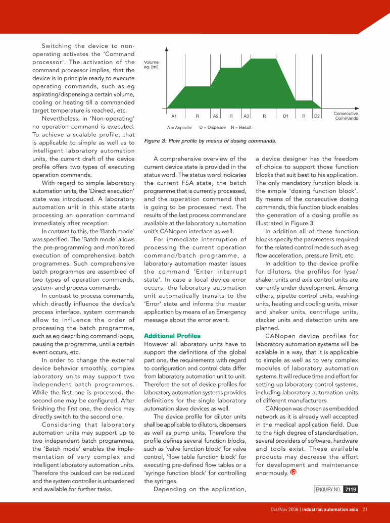
a device designer has the freedom of choice to support those function blocks that suit best to his application. The only mandatory function block is the simple ‘dosing function block’. By means of the consecutive dosing commands, this function block enables the generation of a dosing profile as illustrated in Figure 3.
In addition all of these function blocks specify the parameters required for the related control mode such as eg flow acceleration, pressure limit, etc.
In addition to the device profile for dilutors, the profiles for lyse/shaker units and axis control units are currently under development. Among others, pipette control units, washing units, heating and cooling units, mixer and shaker units, centrifuge units, stacker units and detection units are planned.
CANopen device profiles for laboratory automation systems will be scalable in a way, that it is applicable to simple as well as to very complex modules of laboratory automation systems. It will reduce time and effort for setting up laboratory control systems, including laboratory automation units of different manufacturers.
CANopen was chosen as embedded network as it is already well accepted in the medical application field. Due to the high degree of standardisation, several providers of software, hardware and tools exist. These available products may decrease the effort for development and maintenance enormously.
ENQUIRY NO. 7119
Figure 3: Flow profile by means of dosing commands.
A1
Volumeeg. [ml]
A = Aspirate D = Dispense
ConsecutiveCommands
R = Result
A2 A3 D1 D2R R R R

22 industrial automation asia | April 2008
Asia
22 industrial automation asia | Oct/Nov 2008
I ntelligent safety solutions in the automation components and communication systems enable
integration of safety technology into the machine design. In the sphere of safety sensors these are safety devices that already integrate functional extensions such as muting.
For the evaluation and safety logic – in addition to ‘large’ safety controllers – small, local logic devices are already offered that are scalable to suit the respective task. Inflexible relay logic thus becomes a thing of the past.
Drive technology also offers
integrated safety functions for fast stopping of the drive with short response time, and for safe monitoring of functions such as safe velocity l imitat ion. One of the factors enabling this kind of integration is safe data communication between components.
Protocol FeaturesIn the interest of realising safe data communication over EtherCAT, the Safety-over-EtherCAT protocol has been disclosed within the EtherCAT Technology Group (ETG). The following features were crucial in the development of this protocol:• Compliance with SIL 3 of IEC
61508.• Safeandnon-safe informationon
the same communication system.• Independenceoftheprotocolfrom
the transfer system and medium.• Thelengthofthesafeprocessdata
is not restricted by the protocol.• Very short frame lengths are
possible.• No limitations with regard to
transfer speed and cycle time.
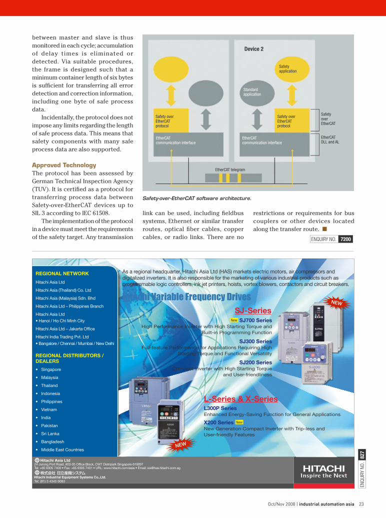
EtherCAT is used as a single-channel communication system for transferring safe and non-safe information. The transport medium is regarded as a ‘black channel’ and not included in safety considerations. A safety frame containing the safe process data and the required data backup is included in the EtherCAT process data. This ‘container’ is safely analysed in the devices at the application level.
Safety-over-EtherCAT therefore uses a unique master/slave relationship between two devices, the Safety-over-EtherCAT connection. This ensures that each device only returns its own new message once a new message has been received.
The complete transfer path
Advanced communication systems not only offer deterministic transmission of control information, they also enable transfer of safety-relevant data over the same medium. By Dr Guido Beckmann, technical committee chairman, ETG
Conventional safety technology compared with advanced machine concepts with integrated safety function.
Standard I/O
Standard I/O
Safetyinputs
Safetyoutputs
Standarddrives
Safetylogic
Relaylogic
PLCFieldbus
Safety/standard I/O
Safety/standard I/O
Safety drives
Safety logic
Standard fieldbusPLC
ASafeSolution
株式会社 日立産機シスラムTel: +81 3 4345 6063 (Japan Office)
ENQU
IRY
NO.
827
Regional netwoRk
Hitachi Asia Ltd
Hitachi Asia (Thailand) Co. Ltd
Hitachi Asia (Malaysia) Sdn. Bhd
Hitachi Asia Ltd – Philippines Branch
Hitachi Asia Ltd
• Hanoi / Ho Chi Minh City
Hitachi Asia Ltd – Jakarta Office
Hitachi India Trading Pvt. Ltd
• Bangalore / Chennai / Mumbai / New Delhi
Regional DistRibutoRs / DealeRs
• Singapore
• Malaysia
• Thailand
• Indonesia
• Philippines
• Vietnam
• India
• Pakistan
• Sri Lanka
• Bangladesh
• Middle East Countries
As a regional headquarter, Hitachi Asia Ltd (HAS) markets electric motors, air compressors and digitalized inverters. It is also responsible for the marketing of various industrial products such as programmable logic controllers, ink jet printers, hoists, vortex blowers, contactors and circuit breakers.
Hitachi Variable Frequency Drives
NEW
sJ-seriessJ700 series
High Performance Inverter with High Starting Torque and Built-in Programming Function
sJ300 seriesFull-feature Performance for Applications Requiring High
Starting Torque and Functional Versatility
sJ200 seriesCompact Inverter with High Starting Torque
and User-friendliness
New
Hitachi asia ltd 24 Jurong Port Road, #03-05 Office Block, CWT Distripark Singapore 619097 Tel: +65 6305 7400 • Fax: +65 6305 7401 • URL: www.hitachi.com/asia • Email: [email protected]
NEW
Tel: (81) 3 4345 6063
l300P seriesEnhanced Energy-Saving Function for General Applications
X200 series New Generation Compact Inverter with Trip-less and User-friendly Features
l-series & X-series
New
April 2008 | industrial automation asia 23Oct/Nov 2008 | industrial automation asia 23
between master and slave is thus monitored in each cycle; accumulation of delay times is eliminated or detected. Via suitable procedures,the frame is designed such that a minimum container length of six bytes is sufficient for transferring all error detection and correction information, including one byte of safe process data.
Incidentally, the protocol does not impose any limits regarding the length of safe process data. This means that safety components with many safe process data are also supported.
Approved TechnologyThe protocol has been assessed by German Technical Inspection Agency (TUV).Itiscertifiedasaprotocolfortransferring process data between Safety-over-EtherCAT devices up to SIL3accordingtoIEC61508.
The implementation of the protocol in a device must meet the requirements of the safety target. Any transmission
link can be used, including fieldbus systems, Ethernet or similar transfer routes, optical fiber cables, copper cables, or radio links. There are no ENQUIRY NO. 7200
restrictions or requirements for bus couplers or other devices located along the transfer route. ■
Safety-over-EtherCAT software architecture.
Device 2
Safety application
Standardapplication
Safety overEtherCAT protocol
Safety overEtherCAT protocol
Safety overEtherCAT
EtherCATDLL and AL
EtherCATcommunication interface
EtherCATcommunication interface
EtherCAT telegram
24 industrial automation asia | Oct/Nov 2008
issues & insights
ntrinsic safety is a method of protection whereby the object or process in question is considered inherently safe. In other words, it is, without any
external interference, free from the threat of harm. It is a requirement that may be applicable to devices that are being operated in areas with flammable gases or fuels.
According to the automation standard ISA-RP12.6, intrinsically safe equipment are ‘equipment and wiring which is incapable of releasing sufficient electrical or thermal energy under normal or abnormal conditions to cause ignition of a specific hazardous atmospheric mixture in its most easily ignited concentration’.
Intrinsically safe products receive their classification
because their electrical power usage is below the level of power required to set off an explosion within a given hazardous area. To add to this, these products are incapable of storing large amounts of energy which might spark an explosion when discharged.
Examples of hazardous areas are environments where flammable gases, vapours and liquids are stored and manufactured. These areas are prevalent in many of today’s manufacturing facilities including chemical plants, paint manufacturers, oil refineries, textile mills, etc.
Traditionally, protection from explosions in a hazardous environment has been achieved by either using explosion proof equipment which is able to contain an explosion
Devices can be approved as intrinsically safe (IS)
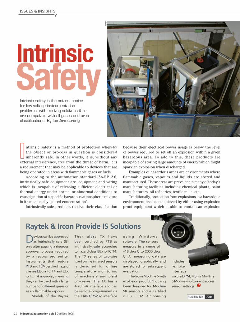
only after passing a rigorous approval process required by a recognised entity. Instruments that feature PTB and TÜV certified hazard classes EEx ia IIC T4 and EEx ib IIC T4 approval, meaning they can be used with a large number of different gases or easily flammable vapours.
Models of the Raytek
The rma le r t TX have been certified by PTB as intrinsically safe according to hazard class EEx ib IIC T4. The TX series of two-wire fixed online infrared sensors is designed for online temperature monitoring of machinery and plant processes. The TX has a 4-20 mA interface and can be remote-programmed via the HART/RS232 interface
u s i n g W i n d o w s software. The sensors measure in a range of –18 deg C to 2000 deg C. All measuring data are displayed graphically and are stored for subsequent evaluation.
The Ircon Modline 5 with explosion proof XP housing been designed for Modline 5R sensors and is certified d IIB + H2. XP housing
includes remote interface via the DPM, MSI or Modline 5 Modview software to access sensor settings.
Raytek & Ircon Provide IS Solutions
Intrinsic safety is the natural choice for low voltage instrumentation problems, with existing solutions that are compatible with all gases and area classifications. By Ian Armstrong
Safety
ENQUIRY NO. 7201
HIM
A
Intrinsic
www.turck.com
TURCK Singapore Pte. Ltd.25 International Business Park, #03-22/23 German Centre, Singapore 609916 Phone +65 6562 8716, Fax +65 6562 8719, E-Mail [email protected]
INTRINSICALLY SAFE REMOTE I/O• High availability Redundant power supplies and gateways as well as system, line and PNO redundancy guarantee high system availability
• Hot-swappable All excom® modules – including power supply and gateway – can be exchanged during operation without restriction
• No signal loss The 230V power supply enables economical standard cabling even over long distances
• Compact In the maximum expansion stage an excom® station can accommodate up to 128 binary or 64 analogue intrinsically safe channels
Point to Point! Point to Bus! Bus to Bus!
TURCK Singapore Pte. Ltd.25 International Business Park, #03-22/23 German Centre, Singapore 609916 25 International Business Park, #03-22/23 German Centre, Singapore 609916 Phone +65 6562 8716, Fax +65 6562 8719, E-Mail [email protected] +65 6562 8716, Fax +65 6562 8719, E-Mail [email protected]
Point to Point! Point to Bus! Bus to Bus! Point to Point! Point to Bus! Bus to Bus!
F0300_80x240_excom_Singapore_GB.indd 1 14.08.2008 09:06:15
ENQ
UIRY
NO.
859
Oct/Nov 2008 | industrial automation asia 25
ENQUIRY NO. 7202
inside an enclosure, or pressurisation or purging, which isolates the explosive gas from the electrical equipment.
Intrinsically safe equipment cannot replace these methods in all existing applications. However, what they potentially offer is significant savings in costs of the installation and maintenance of equipment in the hazardous area.
Elements Of An IS SystemAn intrinsically safe (IS) system is made up of the intrinsically safe device that is located in the hazardous environment, a power limiting device (intrinsically safe barrier or galvanic isolator) located in a non-hazardous area, and the associated wiring.
Intrinsically safe devices typically operate on low voltage DC and consume less than one watt of power. For a manufacturer to achieve intrinsically safe certification of a device, the design and the apparatus itself must be inspected and approved by an appropriate regulating authority.
When IS devices are correctly installed and connected, they are incapable of creating sparks or heat that could cause ignition of the hazardous environment.
Intrinsically safe devices must always be connected to power limiting devices, such as intrinsically safe barriers or galvanic isolators. These barriers are located in a safe, non-explosive environment and are placed between the electrical power supply and the intrinsically safe device. Their goal is to limit the voltage and current available to the intrinsically safe device that is in the hazardous environment.
IS ConfigurationThe elements of IS systems can be organised in several different ways. For instance, IS barriers may be incorporated within an instrument, such as a humidity transmitter with a remote sensor.
The electronic portion of this instrument would be installed in a safe environment and the remote probe installed in the hazardous environment. A system like this would consist of all of the necessary elements for an IS installation and would free the user from having to specify and acquire IS barriers. However, the electronic portion of the instrument could never be mounted in a hazardous location, seriously limiting the flexibility of installation.
Another approach is to separate the IS barriers from the instrument. In this case, the entire instrument and probe can be mounted anywhere within the hazardous environment.
Power and signal wires terminate at the IS barriers in the safe environment allowing for flexibility in installation, but it also requires that the user specify and acquire barriers that are appropriate the installation.

26 industrial automation asia | Oct/Nov 2008
issues & iNsights
he strong growth of the Safety Instrumented Systems (SIS) market will continue in 2008.
However, due to the downturn of the economy in North America the growth rate will be somewhat tempered in subsequent years. The worldwide market, which was around US$1.4 billion in 2007, is expected to grow at a compounded annual growth rate (CAGR) of over 12 percent per year to over US$2.5 billion in 2012, according to the Arc Advisory Group study, ‘Process Safety System Worldwide Outlook – Market Analysis and Forecast Through 2012’.
The safety system market has experienced unprecedented growth for the last two years. Increased demand for oil and gas due to the economic growth of China and India along with the high price of crude oil is fueling investments in oil and gas production and in refining, leading to increased demand for safety systems.
Increased DemandGreater awareness of safety standards, such as IEC 61508, IEC 61511, and ANSI/ISA-84, and
global environmental awareness is increasing the demand for safety systems. Additionally, high profile industrial accidents, such as in the BP Texas refinery in the USA and in the Buncefield terminal in the UK, have increased the sense of vulnerability among ma nufacturers , le ading to increased demand for safety systems. In North America and Western Europe, the obsolescence of older equipment is also leading to greater demands for safety systems.
Safety Lifecycle ManagementAll major safety standards have specified safety lifecycles, which show considerable similarities, differing only in the details. The safety lifecycle, specified by the IEC 61511 standard, shows a systematic approach to safety starting from a hazard and risk analysis to implementation of the safety system and finally to its decommissioning.
With the increased awareness in safety standards, the demand for software that helps in managing the safety lifecycle
is growing rapidly. Many SIS suppliers and third parties, such as system integrators, offer custom consulting in these areas. However, SIS users are now looking for packaged solutions that may help them comply with the standard.
Opportunities In Asia & Middle EastThe EMEA region is the largest market for sa fety systems, followed by Asia and North America. With the booming economy of China and India, the Asian region will show highest growth. The EMEA region will also show a large growth in the market as the high price of crude oil will lead to significant investments in grass-root facilities in the Middle East and parts of Europe.
Process Safety System Market Shows Unprecedented Growth
Market Report:
The SIS market is expected to grow at a CAGR of over 12 percent per year to over US$2.5 billion in 2012. By Asish Ghosh, VP, Manufacturing Advisory Services, Arc Advisory Group
ENQUIRY NO. 7203
3,000.0
2007
2008
2009
2010
2011
2012
Safety System Business Worldwide ($Millions)