Introduction to the New VAT on Property System Ronan O’Grady BBLS (European), AITI)
Upload
doannguyetCategory
view
217download
2
CBM 93-01
WELL COMPLETION REPORT
Basic Data
EP 93
Northern Territory
Central Petroleum Limited

CBM 93-001 Well Completion Report: Basic Data
Page 2 of 20
Table of Contents
1.0 Introduction and Summary ............................................................................... 3 2.0 General Data ................................................................................................... 5 3.0 Drilling ............................................................................................................. 6
• 3.1 Summary of Drilling and Related Operations .............................................................. 6 • 3.2 Particulars of Drilling ................................................................................................... 9 3.2.1 Particulars of the casing and equipment installed in the well ..................................... 10 3.2.2 Particulars of cementing operations carried out ......................................................... 10
4.0 Logging, Sampling and Testing ..................................................................... 12 • 4.1 Cores Cut .................................................................................................................. 12 • 4.2 Cuttings Samples Collected ...................................................................................... 13 • 4.3 Mudlogging ................................................................................................................ 13 • 4.4 Wireline Logging ....................................................................................................... 13 • 4.5 Drill Stem Testing ...................................................................................................... 13
5. Geology and Formation Evaluation .................................................................. 15 • 5.1 CBM 93-001: Regional Geological Setting ............................................................... 15 • 5.2 Well Lithology and Formation Tops ......................................................................... 16 • 5.3 Hydrocarbon Indications ............................................................................................ 16 5.3.1 Gas Shows from Purni Formation Coals .................................................................... 16 5.3.2 Purni Formation- Net Cumulative Coal Thickness ..................................................... 17 • 5.4 Reservoir Quality ....................................................................................................... 18 5.4.1 Cretaceous/Jurassic Section ..................................................................................... 18 • 5.5 Source Rock Quality ................................................................................................. 20
6.0 References ................................................................................................... 20 TABLES
TABLE 1: WELL INDEX SHEET ....................................................................................... 4 TABLE 2: CBM 93-001 Bit Record .................................................................................. 11 TABLE 3: CBM 93-01 Deviation Surveys ....................................................................... 11 TABLE 4: CBM 93-001 Drilling Fluid Properties .............................................................. 12 TABLE 5: List of Cores Cut and Core Recovery (Geologists Record) ............................. 12 TABLE 6: Wireline Logs Recorded .................................................................................. 13 TABLE 7: Predicted Depths versus Actual Depths .......................................................... 16 TABLE 8: GAS READINGS – PURNI FORMATION COALS* ......................................... 16
FIGURES Figure 1: CBM-001 Location Map ..................................................................................... 3 Figure 2: Drilling time vs depth .......................................................................................... 6 Figure 3: CBM-001 Wellbore Schematic at suspension .................................................. 10 Figure 4:Structural Elements EP 93, Pedirka Basin ........................................................ 15

CBM 93-001 Well Completion Report: Basic Data
Page 3 of 20
1.0 Introduction and Summary CBM 93-001 was drilled by Central Petroleum Limited in Northern Territory Exploration Permit 93. Hunt Rig No.2 was mobilized to the CBM 93-001 after the drilling of the Blamore No.1 exploration well, located approximately 60km SE of the CBM 93-001 and approximately 275km SE of Alice Springs (Figure 1). CBM 93-001 was spudded on 28th August 2008 and reached Total Depth of 1265m on 19th September 2008. Figure 1: CBM-001 Location Map
The well was drilled specifically to investigate the potential for CBM (Coal Bed Methane) and UCG (Underground Coal Gasification) gas production from Permian Purni Formation coal seams. CBM 93-001 intersected a number of thick coals in the Purni Formation with a net cumulative coal thickness of 138m, for coal seams greater than 2m thickness; with a total 153m thickness for all coals including thin beds (Al Maynard & Associates, 2009). Total thickness of coals was slightly greater in CBM 93-001 compared to the thickness of coal in the Blamore No.1 well, with both wells intersecting significantly more coal than any other wells in the Pedirka Basin. Thirty Four cores were cut using a continuous wireline retrievable coring system. Two drill stem tests conducted to assess coal permeability. The well was cased and suspended at total depth to allow for production testing at a later date. A 4 ½” solid liner interspersed with joins which had six 0.5” holes per foot was run to a depth of 1187m and set on a tubing hanger in the 7” casing at 690m. The rig was released on the 21st September 2008.
CBM 93-001 Well Completion Report: Basic Data
Page 4 of 20
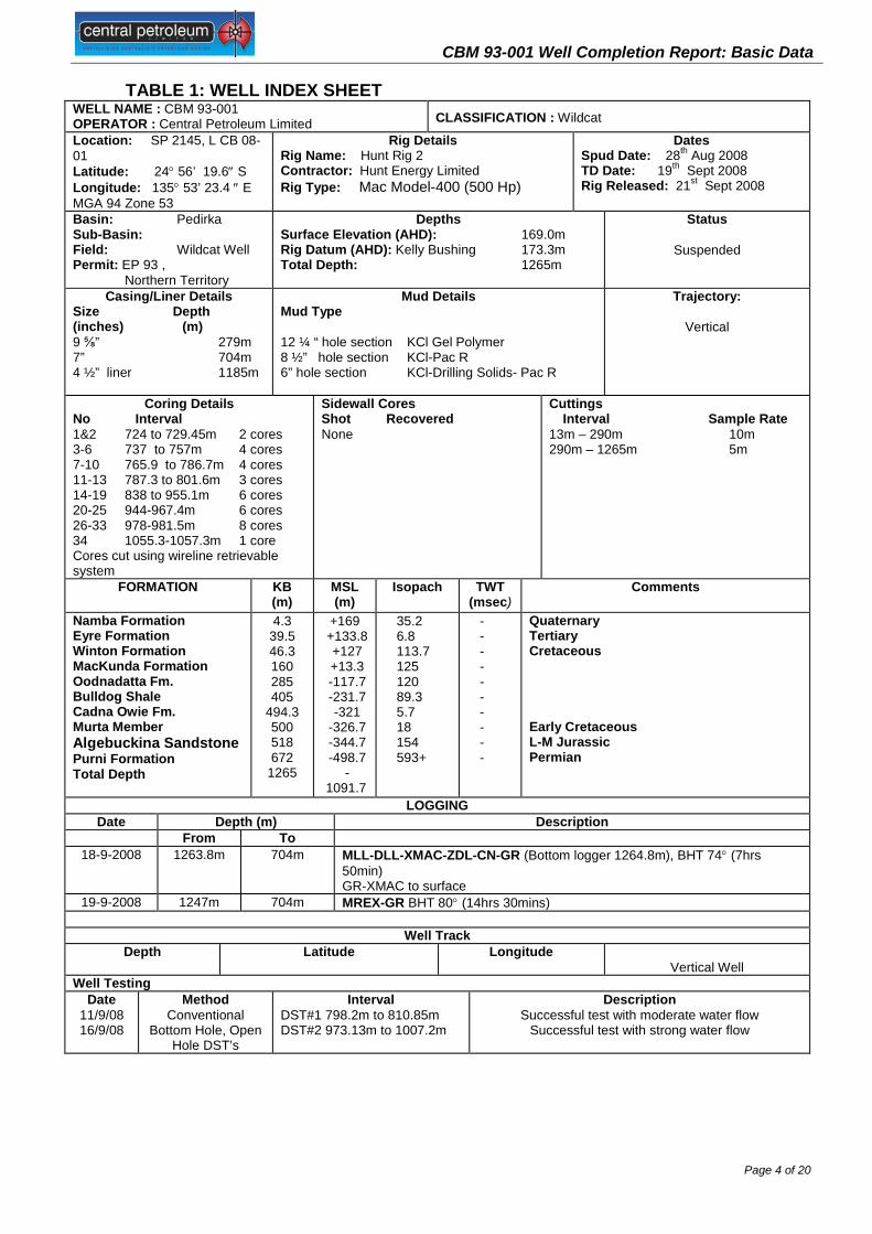
TABLE 1: WELL INDEX SHEET WELL NAME : CBM 93-001 OPERATOR : Central Petroleum Limited CLASSIFICATION : Wildcat Location: SP 2145, L CB 08-01 Latitude: 24° 56’ 19.6″ S Longitude: 135° 53’ 23.4 ″ E MGA 94 Zone 53
Rig Details Rig Name: Hunt Rig 2 Contractor: Hunt Energy Limited Rig Type: Mac Model-400 (500 Hp)
Dates Spud Date: 28th Aug 2008 TD Date: 19th Sept 2008 Rig Released: 21st Sept 2008
Basin: Pedirka Sub-Basin: Field: Wildcat Well Permit: EP 93 , Northern Territory
Depths Surface Elevation (AHD): 169.0m Rig Datum (AHD): Kelly Bushing 173.3m Total Depth: 1265m
Status
Suspended
Casing/Liner Details Size Depth (inches) (m) 9 ⅝” 279m 7” 704m 4 ½” liner 1185m
Mud Details Mud Type 12 ¼ “ hole section KCl Gel Polymer 8 ½” hole section KCl-Pac R 6” hole section KCl-Drilling Solids- Pac R
Trajectory:
Vertical
Coring Details No Interval 1&2 724 to 729.45m 2 cores 3-6 737 to 757m 4 cores 7-10 765.9 to 786.7m 4 cores 11-13 787.3 to 801.6m 3 cores 14-19 838 to 955.1m 6 cores 20-25 944-967.4m 6 cores 26-33 978-981.5m 8 cores 34 1055.3-1057.3m 1 core Cores cut using wireline retrievable system
Sidewall Cores Shot Recovered None
Cuttings Interval Sample Rate 13m – 290m 10m 290m – 1265m 5m
FORMATION
KB (m)
MSL (m)
Isopach TWT (msec)
Comments
Namba Formation Eyre Formation Winton Formation MacKunda Formation Oodnadatta Fm. Bulldog Shale Cadna Owie Fm. Murta Member Algebuckina Sandstone Purni Formation Total Depth
4.3 39.5 46.3 160 285 405
494.3 500 518 672
1265
+169 +133.8 +127 +13.3 -117.7 -231.7 -321
-326.7 -344.7 -498.7
-1091.7
35.2 6.8 113.7 125 120 89.3 5.7 18 154 593+
- - - - - - - - - -
Quaternary Tertiary Cretaceous Early Cretaceous L-M Jurassic Permian
LOGGING Date Depth (m) Description
From To 18-9-2008 1263.8m 704m MLL-DLL-XMAC-ZDL-CN-GR (Bottom logger 1264.8m), BHT 74° (7hrs
50min) GR-XMAC to surface
19-9-2008 1247m 704m MREX-GR BHT 80° (14hrs 30mins)
Well Track Depth
Latitude
Longitude
Vertical Well Well Testing
Date 11/9/08 16/9/08
Method Conventional
Bottom Hole, Open Hole DST’s
Interval DST#1 798.2m to 810.85m DST#2 973.13m to 1007.2m
Description Successful test with moderate water flow
Successful test with strong water flow
CBM 93-001 Well Completion Report: Basic Data
Page 5 of 20
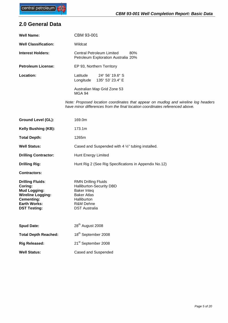
2.0 General Data Well Name: CBM 93-001 Well Classification: Wildcat Interest Holders: Central Petroleum Limited 80% Petroleum Exploration Australia 20%
Petroleum License: EP 93, Northern Territory Location: Latitude 24° 56’ 19.6″ S Longitude 135° 53’ 23.4” E
Australian Map Grid Zone 53 MGA 94
Note: Proposed location coordinates that appear on mudlog and wireline log headers have minor differences from the final location coordinates referenced above.
Ground Level (GL): 169.0m Kelly Bushing (KB): 173.1m Total Depth: 1265m Well Status: Cased and Suspended with 4 ½” tubing installed. Drilling Contractor: Hunt Energy Limited
Drilling Rig: Hunt Rig 2 (See Rig Specifications in Appendix No.12) Contractors: Drilling Fluids: RMN Drilling Fluids Coring: Halliburton-Security DBD Mud Logging: Baker Inteq Wireline Logging: Baker Atlas Cementing: Halliburton Earth Works: R&M Dehne DST Testing: DST Australia Spud Date: 28th August 2008 Total Depth Reached: 18th September 2008 Rig Released: 21st September 2008 Well Status: Cased and Suspended

CBM 93-001 Well Completion Report: Basic Data
Page 6 of 20
3.0 Drilling
3.1 Summary of Drilling and Related Operations Hunt Rig 2 mast was raised on the 27th August 2008. Drilling of the 24” conductor hole to 13m (8m below the base of the cellar) and the running and cementing of the 16” conductor pipe were carried out without incident. Figure 2 presents drilling time vs depth.
Figure 2: Drilling time vs depth
Drilling 12¼” Hole and Setting 9⅝” Surface Casing CBM 93-001 was spudded at 2000 hours on the 28th August 2008 (incorrectly stated as 29th August 2008 in drilling reports 9 and subsequent reports). The 12¼” surface hole was drilled to a depth of 280m without incident. At the base of loose surface sands a slow drilling silcrete was encountered between 39.5m to 46.3m. Below this hard band the Winton Formation was intersected. This consists of claystone. Very heavy cavings up to and greater than 2cm in length were observed on the shaker screen while drilling from 100m to 230m, with moderately heavy cavings observed to 280m, which was the casing point. 9⅝” casing was run free to 20m, worked and washed from 20m to 108m, with particular difficulty running through the silcrete horizon noted above. The casing was then run free to a depth of 279m. The casing was cemented with 64.9 bbls of 11.9ppg lead and 16.8 bbls of 15.8ppg tail cement. Cement was returned to surface prior to the plug bumping. This operation was completed 30th August 2008. Drilling 8½” Hole

CBM 93-001 Well Completion Report: Basic Data
Page 7 of 20
After the blowout preventer was nippled up, drilling of the 8½” hole commenced on the 1st September 2008. Three metres of new hole were drilled to 283.5m whereupon a formation integrity test was carried out. With 8.7ppg mud in the hole a maximum pressure of 475 psi (equivalent mud weight of 18.7 ppg) was recorded with no leak off. Drilling progressed quickly to 705m, with a claystone-dominant sequence drilled to the top of the Cadna Owie Formation at 494.3m, below which relatively coarse loose sands were predominant. A wiper trip was performed to clean up the hole before running 7” casing. Tight hole (5 to 10K overpull) was experienced on pulling out through the Cadna Owie and Algebuckina Sandstone from 596m to 491m, presumed due to mudcake buildup. The program called for setting the intermediate casing at the top of the Purni Formation in order to isolate this formation from the overlying the Algebuckina Sandstone artesian aquifer. Running 7” Intermediate Casing The 7” casing was run without incident and set at 704m. The casing was cemented with 71 bbls of 13.5ppg cement. After 6 hrs of waiting on cement, a 45 sx cement top job was done to finish the 7” cement job. This cement job was completed 3 September 2008. Drilling and Coring 6” Hole It should be noted the daily drilling reports are incorrect in detail and should not be relied upon in respect to sequence of events. After some preparation, drilling of the 6” hole commenced on 5 September 2008, using a wireline retrievable coring system that had the capability of drilling conventional hole. The coring system used was the Halliburton-Security DBS Latch-Les Wireline System. The system could be operated in drilling mode with a drill plug inserted in the core head. On the decision to commence coring the drill plug is removed by wireline and coring proceeds with the cut core entering an inner core barrel which, after cutting of a core, can be retrieved by wireline. In drilling mode, two metres of cement and formation were drilled from 704m to 706m (1m new hole) An FIT was conducted to 1000psig with 9ppg mud. The ECD was 17.3ppg. At 724m (incorrectly stated to be 726m in Daily Drilling Report 16) it was decided to drill Core #1. The inner core barrel got stuck while heading into the hole at 249m, this found to be the case when the Weatherford wireline was run in the hole to retrieve the drill plug from the core head, the retrieving tool hit the stuck inner core barrel at speed and it broke (drilling reports not clear on this sequence). It was later discovered the drill pipe had not been drifted properly and could not allow the inner core barrel past. The drill pipe was pulled to recover the inner core barrel. The drill pipe was then drifted resulting in the removal of several joints and later after a check run of the inner core barrel on slick line, the removal of 5 drill collars with under gauge ID due to the buildup of scale. With the retrieving tool broken, the cores could not be pulled by wireline until spare part could be sourced. Coring continued by running and pulling drill pipe with two cores cut as follows: Core #1 724m to 727m Core #2 728m to 729.45m The bottom core depth for Core#2 was reported as 737m, drillers depth, however core jam occurred at 729.45m and hole was effectively drilled to 737m. The retrieving tool was repaired on site and continuous wireline retrievable coring proceeded with the following cores cut. Core #3 737m to 738m (735.6m to 738m; depth core hand) Core #4 738m to 744.5m Core #5 744.5m to 752m Core #6 752m to 757m Only sandstone was recovered in these cores. It was then decided to drill ahead. At a depth of 765.9m it was decided to resume coring. Due to an error of judgment the repaired wireline retrieval tool was again broken and therefore core retrieval was effected by tripping the pipe out of the hole.

CBM 93-001 Well Completion Report: Basic Data
Page 8 of 20
Core #7 765.9m to 770.9m Core #8 770m to 775m Core #9 775m to 781.3m Core #10 781.3m to 786.7m At this point while running in the hole at pipe depth 606m, the Hunt drilling crew dropped the drill pipe 180m to the bottom of the well. The drill pipe was fished from the well and the bit and core barrel were changed out as both had been damaged. Return in hole with core barrel, drill the following cores: Core #11 787.3m to 794.8m Core #12 794.8m to 798.2m Core #13 798.2m to 801.6m The well was then drilled to 810.9m and circulated while waiting on packer rubbers (only 7” rubbers on site) for the drill stem test tools. Drill Stem Test #1 The first drill stem test (DST) was conducted on an interval between 798.2m and 810.9m. The tools were run into the hole with 154.7m of water cushion. Duration of pre-flow was 20 minutes. An initial moderate blow declined to weak during the flowing period. Duration of initial shut in was 120 minutes and was followed by an initial flow of 30 minutes, with a weak to very weak flow. Duration of subsequent shut-in was 156 minutes. The test was conducted to assess coal seam permeability and fluid recovery. This successful test was conducted on 11th September 2008. Drilling and Coring 6” Hole – Continued The well was drilled from 810.6m to 838m until another significant coal was intersected. By now, the wireline retrieving tool parts had been replaced. It was found that large core sections were too difficult to remove from the barrel; smaller sections were cut in an attempt to speed up the recovery time. The following cores were the cut: Core #14 838m to 842m Core #15 842m to 844m Core #16 844m to 847m Core #17 847m to 849.7m Core #18 849.7m to 852.1m Core #19 852.1m to 855.1m The well was then drilled from 855m to 927m Pressure problems plagued drilling during this period so the bit was pulled out of the hole. The ports were found to be plugged with ½” rock fragments. The same corehead was ran into the hole and drilled to 944m. The drill plug was retrieved on wireline and the following cores were obtained on 14th September: Core #20 944m to 944.4m (jammed-no recovery) Core #21 944.4m to 947.4m Core #22 947.4m to 951.9m Core #23 951.9m to 958.9m Core #24 958.9m to 963.4m core jammed Core #25 963.4m to 967.4m The core head was changed at this point. The well was drilled to 978m at which point the drill plug was removed and the following cores were cut: Core #26 978m to 981.5m Core #27 981.5m to 985.5m Core #28 985.5m to 988.5m Core #29 988.5m to 991.5m

CBM 93-001 Well Completion Report: Basic Data
Page 9 of 20
Core #30 991.5m to 995.7m Core #31 995.7m to 998.7m Core #32 998.7m to 1004.7m Core #33 1004.7m to 1006.5m A decision was made to run DST No.2 after Cores 26 to 33 cut one continuous seam of coal. Drill Stem Test #2 Drill Stem Test No.2 was conducted over the interval 973.13m to 1007.2m. A 148m water cushion was used. Duration of the pre-flow was 20 minutes. A very strong blow decreasing to a strong blow was observed before being shut in for 120 minutes. Duration of the initial flow lasted for 30 minutes and went from a strong blow to moderately strong blow before shutting in for 300 minutes. The test was conducted to assess the permeability of a coal seam. The test was successful. This operation was conducted 16 September 2008. Drilling and Coring 6” Hole – Continued The remaining part of the well was drilled from 17th September to 18th September 2008. One core was cut during this time. It was: Core #34 1055.3m to 1057.3m (adjusted depths used by GeoGas: 1052.9m to 1054.9m) At 1218m the mud weight was raised after it was established that water was flowing into the well bore. Mud weight was raised to 9.3 ppg to kill this flow and then to 9.5 ppg after a wiper trip made prior to wireline logging. It appears that a fault was drilled into at this depth, this further discussed in Section 5.4.2.1. Wireline Logging and Suspension of the Well. Wireline logging commenced on the 18th September 2008 and was completed 19th September 2008 (two logging runs).
A cement plug was then laid from 1265m to 1185m to isolate the section below all significant Purni Formation Coals in order to seal of the zone that appeared to flow formation water. Cement was tagged at 1188m. A 4½” liner was hung from the 7” liner on a tubing anchor at 690m to and run to a depth of 1187m. The liner included both plain and pre-drilled joints. The pre-drilled holes were at 6 holes per foot at 0.5” diameter per hole. The tally is included in the Appendix No.1 of this report. The rig was released at 1400hrs 21st September 2008.
3.2 Particulars of Drilling
Figure 4 is a schematic diagram of the wellbore as suspended.

CBM 93-001 Well Completion Report: Basic Data
Page 10 of 20
Figure 3: CBM-001 Wellbore Schematic at suspension
3.2.1 Particulars of the casing and equipment installed in the well
Conductor Casing – 16” conductor pipe was set at 13m Surface Casing – 9⅝” casing was set at 279m. Intermediate Casing – 7” casing was set at 704m Completion – 4½” 13.5#P110 BTC Liner hung in 7”liner and run to depth 1187m. The pipe tally for the 4½” tubing is included within Appendix No.1 of this report. Suspension – The well was plugged back to 1188m prior to running the 4½” Liner. A 7½” Blank Flange was installed at the surface. CBM 93-001 was suspended on 21st September, 2008. 3.2.2 Particulars of cementing operations carried out The following cementing operations were performed: Conductor Casing – A 24” hole was augered to 13m, 8m below the cellar floor. The 16” conductor pipe was cemented in place with 240 sxs of Class A cement on 27th August, 2008. Surface Casing – On 30th August, 2008, 9⅝” 36ppf BTC K-55 R3 casing was cemented in a 12¼” hole at a depth of 279m. An 11.8ppg lead slurry consisting of 64.9bbls (140 sxs) Class G was pumped. This was followed by 16.8ppg tail slurry consisting of 16.8bbls (81 sxs). Displacement was with water. Cement had returned to surface when the plug bumped. Casing was pressure tested. No operations occurred over the next 3.5hrs while cement cured to an adequate hardness.

CBM 93-001 Well Completion Report: Basic Data
Page 11 of 20
Intermediate Casing – 7” 23ppf K55 BTC R3 was cemented in an 8½” hole below the 9⅝” casing at a depth of 704m. It was cemented with 71bbls of 13.5 ppg cement. Adequate displacement of water left the cement top to 30 meters above the 9⅝” shoe. This operation took place 3 September, 2008. Plug Back – While drilling a water zone started flowing into the well. A cement plug was laid across this interval to prevent any future cross-flow into the coal sections. The plug was set from 1185m to 1265m using 11bbls (55 sx) of Class G 16.0 ppg cement. Plug was tagged at 1188m. 3.2.4 Bit Records Bits utilized and record summary for these are detailed in table 3 below. TABLE 2: CBM 93-001 Bit Record Bit # Size Manufacturer Type Jets Hole
Drilled Hours
1 12.25” Stealth JST 11XC
3X16,14 259m 10.5
2 8.5” Stealth S36 PDC
3X16 424.5m 14.5
¾ 6” Corehead FC 3643
106m 33.5
5 6” Corehead CT103 180m 44 6 6” Corehead CD93 309m 32 3.2.5 Deviation Surveys Deviation surveys were taken using a TOTCO survey tool with a 0-8° range with a single shot survey barrel. Survey results were: TABLE 3: CBM 93-01 Deviation Surveys
Depth (m) Dev (degrees) 40 ¼
86 ¼
160 ½
422 2 ½
575 misrun 3.2.6 Drilling Fluids RMS Drilling Fluids were contracted to supply and maintain drilling fluids.
12¼” Hole 13m to 280m Gel Spud Mud, Mud Weight 8.9 ppg 8½” Hole 280m to 705m KCl/ Pac-R, Mud Weight 8.7 to 9.2 ppg 6” Hole 705m to 1265m (TD) KCl/Drilled Solids/Pac-R, 8.8 to 8.9 ppg The RMS Drilling Engineer was released from the drilling location on 16th September 2008 for family reasons. A detailed summary of drilling fluid properties prepared by RMS Drilling Fluids is contained in Section 5, Drilling Fluid Summary – Mud Recap which is located in Appendix No.10

CBM 93-001 Well Completion Report: Basic Data
Page 12 of 20
Drilling Fluid properties for the period after release of the RMS Drilling Engineer are recorded in the Daily Drilling Reports and summarized below in Table 4: TABLE 4: CBM 93-001 Drilling Fluid Properties 16 Sep 17 Sep 18 Sep 19 Sep 20 Sep 21 Sep Weight – ppg 8.8 8.9 9.5* 9.5 9.3 8.9 Vis 39 35 37 37 37 35 API WL 8.0 8.0 8.0 8.0 8.0 FC 1 1 1 1 1 pH 9.0 9.0 9.0 9.0 9.0 9.0
* Mud Weight was raised to 9.5 ppg at 1218.5m after water flowed into the well bore.
3.2.7 Lost Time A total of 52 hrs were tallied as lost time. Thirty percent of this was associated with rig problems, sixty-two percent was due to incorrect packer rubbers on the DST equipment, four percent was attributed to the mechanical problems with Halliburton cementing equipment and four percent was assigned to waiting on orders. A detailed breakdown is located in the Appendix No.1.
3.2.8 Water Supply Water for drilling purposes was taken from a water bore located 20km from the location. This bore, Bravo Bore, also provided a water source for drinking after the water was run through an osmosis machine.
4.0 Logging, Sampling and Testing CBM 93-001 was drilled to investigate the potential of the Permian Purni Formation coals, a series of thick coals with a cumulative thickness of greater than 100m. A series of cores were cut and coal core samples were placed in canisters for desorption analysis. Two drill stem tests were conducted on coal seams to assess their permeability. Standard mudlogging services were utilized throughout the drilling of the well and a full suite of standard wireline logs were recorded, with a nuclear magnetic resonance tool also being run.
4.1 Cores Cut The coring system used was the Halliburton-Security DBS Latch-Les Wireline System. The system could be operated in drilling mode with a drill plug inserted in the core head. On decision to commence coring the drill plug is removed by wireline and coring proceeds with the cut core entering an inner core barrel which, after cutting of a core can be retrieved by wireline. TABLE 5: List of Cores Cut and Core Recovery (Geologists Record)
Core Head Core# Depth Interval Length Cut
Recovery
FC3643 1 724m to 727m 3.00m 1.38m / 46% 2 728m to 729.45m 1.45m 1.45m / 100% 3 737m to 738m 1.0m 0.48m /48% 4 738m to 744.5m 6.5m 1.45% / 22% 5 744.5m to 752m 7.5m 0.86m / 12% 6 752m to 757m 5.0m 0.6m / 12%
CT 103 (1) 7 765.9m to 770.9m 5.0m 1.45m / 29% 8 770m to 775m 5.0m 4.33m / 87% 9 775m to 781.3m 6.34m 6.34m / 100% 10 781.3m to 786.7m 5.0m 4.04m / 81%
CT 103 (2) 11 787.3m to 794.8m 7.5m 7.3m / 97% 12 794.8m to 798.2m 4.2m 3.32m / 79% 13 798.2m to 801.6m 5.0m 3.4m / 68% 14 838m to 842m 4.0m 3.0m / 75% 15 842m to 844m 2.0m 0.8m / 40%

CBM 93-001 Well Completion Report: Basic Data
Page 13 of 20
16 844m to 847m 3.0m 3.06m / 100% 17 847m to 849.7m 2.7m 1.03m / 38% 18 849.7m to 852.1m 2.4m 2.1m / 88% 19 852.1m to 855.1m 3.0m 2.83m / 94% 20 944m to 944.4m 0.4m 0 21 944.4m to 947.4m 3.0m 2.54m / 85% 22 947.4m to 951.9m 4.5m 4.02m/ 89% 23 951.9m to 958.9m 7.0m 6.22m / 89% 24 958.9m to 963.4m 4.5m 4.57m / 100% 25 963.4m to 967.4m 4.0m 4.06m / 100%
CD 93 26 978m to 981.5m 3.5m 3.5m/ 100% 27 981.5m to 985.5m 4.0m 4.0m/ 100% 28 985.5m to 988.5m 3.0m 3.0m/ 100% 29 988.5m to 991.5m 3.0m 3.0m/ 100% 30 991.5m to 995.7m 4.2m 4.2m/ 100% 31 995.7m to 998.7m 3.0m 0.8m / 27% 32 998.7m to 1004.7m 6.0m 6.0m/ 100% 33 1004.7m to 1006.52m 1.82m 1.82m/ 100% 34 1055.3m to 1057.3m 2.0m 2.0m/ 100%
Note: There is a variance between drill and wireline depths of Core No. 34, 1055.3m to 1057.3m, coring depth as recorded by Halliburton, Core Descriptions and Core Desorption Results as detailed in Appendix Numbers 4, 5 and 6. Drill depths were adjusted directly after drilling Core No.34, pipe tally error, with 2.4m being subtracted from the tally, see GeoGas depth correction table Appendix No.6.
4.2 Cuttings Samples Collected 10m sample interval, washed and dried cuttings samples were collected from 13m to 290m. 5m sample interval, washed and dried cuttings samples were collected from 290m to 1265m. Selected samples were collected for Palynological assessment, see Appendix No.9
4.3 Mudlogging Standard mudlogging services were provided by Baker Inteq for the duration of the well. The mudlog for the well is included as Enclosure No.2 of this report. A final well report is provided by Baker Inteq and is included in this document as Appendix No.11.
4.4 Wireline Logging Wireline logging services were provided by Baker Atlas. Two runs were made, the first a combination tool, the GSlam and the second a Nuclear Magnetic Resonance Tool (MREX) as tabled below: TABLE 6: Wireline Logs Recorded Loggers Bottom Hole Depth was 1264.8m (Drillers 1265m): Casing Depth 704m (wireline and drillers). Basic wireline log data is included in Appendix No.8.
4.5 Drill Stem Testing
Log Run – Date
Type of Log From Depth (m)
To Depth (m)
Comment
1 – 18/9/08 MLL-DLL-XMAC-ZDL-CN-GR
1268.3 704 GR-Sonic to Surface BHT 74° C (7hrs 50mins)
2 – 19/9/08 MREX-GR 1247 704 BHT 80° C (14hrs 30mins)

CBM 93-001 Well Completion Report: Basic Data
Page 14 of 20
Two conventional bottom hole, open hole drill stem tests were conducted in the CBM 93-001 well to assess the potential permeability of two separate coal seams. No hydrocarbon gas was detected by hand held detector at surface. Drill Stem Test No.1, 798.2m to 810.83m The test was successful recording a moderate flow of formation water into the drill pipe. Down hole pressures were successfully recorded. A downhole temperature of 135.97° F (57.2° C) was recorded. Drill Stem Test No.2, 973.13m to 1007.2m The test was successful recording a moderately strong flow of formation water into the drill pipe. Down hole pressures were successfully recorded. A downhole temperature of 155.15° F (67.7°C) was recorded.
Details of the Drill Stem Test Results can be found in Appendix No.7 of this report and results are further discussed in Section 5.4 of this report. MBA Petroleum Consultants in collaboration with Kamenar & Associates prepared an analysis of the results of both drill stem tests. Their report is included in Appendix No.7. Both intervals were reversed circulated after the tests were conducted. Fluid recovery was analyzed by Amdel with the results of formation and other fluid analyses also included in Appendix No.7. 4.6 Coal Desorption Testing A total of 60 core samples, generally 0.5 to 0.7m in length were placed in GeoGas supplied canisters and Q1 measurements were made using GeoGas methods as soon as practically possible after cores were brought to the surface. The canisters were then resealed and shipped to GeoGas for further desorption analysis. Of the samples dispatched further analyses was carried out in laboratory conditions. Further details and results are discussed in Section 5.3.3 of this report and data collected, background information on GeoGas methodology and a report on the results by GeoGas are included in Appendix No.6.

CBM 93-001 Well Completion Report: Basic Data
Page 15 of 20
5. Geology and Formation Evaluation
5.1 CBM 93-001: Regional Geological Setting The Pedirka area occupies the Simpson Desert and encompasses four vertically stacked sedimentary basins, namely the Palaeozoic Warburton Basin, the Permo-Carboniferous Pedirka Basin, the Triassic Simpson Basin, and the Jurassic-Cretaceous Eromanga Basin. The basins are superimposed to some extent and over wide areas reflect a structural footprint controlled by Palaeozoic structuring and palaeo-depositional facies.
Figure 4:Structural Elements EP 93, Pedirka Basin
This well targeted the early Permian Purni Formation coal sequence on the western rampart of the Pedirka Basin named the Andado Shelf. At this location the Algebuckina Sandstone disconformably overlies the Purni Formation, as the Triassic sequence (Walkandi Formation) and possibly the early Jurassic Poolowanna Formation onlap the shelf downflank from the well.
The stratigraphic section is very similar to that encountered in Blamore-1, 50 km to the southeast. This is true for the Jurassic- Cretaceous section and a full section is recorded – i.e. Winton Formation, Oodnadatta Formation, Bulldog Shale, Cadna-Owie Formation, Murta Member and Algebuckina Sandstone. The Poolowanna Formation was thin in Blamore -1 and absent in CBM 93-001 but may be present downflank in the Eringa Trough and also further east in the Madigan Trough.
The early Permian Purni Formation was similar to that intersected in Blamore-1 which confirmed pre-drill seismic correlations. This sequence was 568m+ thick with the coal bearing Upper Purni 521.5m thick in and included 138 m of coal.
The well reached TD at 1265m in what was interpreted to be lower Purni Formation and there were no lithologies penetrated to suggest the Tirrawarra /Crown Point Formation was intersected.

CBM 93-001 Well Completion Report: Basic Data
Page 16 of 20
5.2 Well Lithology and Formation Tops
Drill Cuttings sample lithological descriptions and SWC descriptions are included within this report as Appendix 3. Table 4 shows predicted vs actual Formation Top depths TABLE 7: Predicted Depths versus Actual Depths
5.3 Hydrocarbon Indications 5.3.1 Gas Shows from Purni Formation Coals
Gas readings recorded while drilling Purni Formation Coals are summarized in the table below TABLE 8: GAS READINGS – PURNI FORMATION COALS*
Formation Tops CBM 93-01
Prognosed Depths Final Depths Difference High / Low
(mKB) (mSS) (mKB) (mSS) To Prog Surficial & Namba Fm 4.3 (GL) +169
Eyre Fm 39.5 +133.8
Winton Fm 46.3 +127 MacKunda Formation 160 +13.3
Oodnadatta Fm 285 -111.7 Toolebuc Fm absent
Bulldog Shale 427 -254 405 -231.7 +22 Cadna-owie Fm 568 -395 494.3 -321 +74
Murta Fm 500 -326.7 Algebuckina Sandstone 518 -344.7 Poolowanna Formation - - - - Peera Peera Formation - - - -
Walkandi Formation - - - - Purni Formation 704 -531 672 -498.7 +32
Tirrawarra Sandstone Not reached Crown Point Formation 1150 -977 Not reached
Warburton Basin (?) 1195 1022 Not reached TD 1225 1265

CBM 93-001 Well Completion Report: Basic Data
Page 17 of 20
The data in the table was compiled from the Daily Geological Reports.* Total Gas numbers quoted, one unit = 200ppm C1.
A feature of the gas readings was the relatively high percentage values of C2+ values from the deeper part of the formation. In general the total gas readings increased with depth reflective of increasing coal maturity, with low gas readings recorded for the shallower coals intersected by the well. During coring operations, at times the gas peaks did not correlate with drilling of the coals, partly as a result of migration up hole, giving a somewhat jagged appearance on the mudlog for thicker coal seams with multiple cores. There was a shift on the chromatograph trace at about the iC4 peak, which appeared to be responsible for erroneous high values of iC4. 5.3.2 Purni Formation- Net Cumulative Coal Thickness
This section is included in the Hydrocarbon Shows section of this report as the coals are a potential gas resource particularly when considering the potential for Underground Coal Gasification (UCG) and Coal Bed Methane (CBM) gas production. 5.3.3 Gas Desorption Results from Purni Formation Coal Cores
A total of 60 core samples, generally 0.5 to 0.8m in length were placed in GeoGas supplied canisters and Q1 measurements were made using GeoGas methods as soon as practically possible after cores were brought to the surface. The canisters were then resealed and shipped to GeoGas for further desorption analysis. Of the samples dispatched further analyses was carried out in laboratory conditions. Data collected, information and summary GeoGas report are included in Appendix No.6.
Retrieval time, getting the cores to the surface and off the drill floor thence into canisters was relatively slow compared to that using smaller rigs more commonly used for CBM exploration. Retrieval time of the shallower cores was further compromised after the breakage of the wireline retrieval tool, resulting in the requirement to pull the drill pipe. After repair and eventually replacement of the retrieval tool and with improvement in organization, retrieval time improved. The main problem experienced, that caused considerable delay in getting coal core into canisters, was time spent removing core from the inner core barrel when brought to the surface. For the most part cores were jammed tightly in the core barrel, particularly the coals but also the coarser sandstone which had coarse angular grit protruding from the core surface. A summary report was prepared by Graham McClung, “Review of Coal Desorption Work” and he also made note on the 798.7m and 806m coal core, both dealing
Coal Seam Depth Interval (m)
Thick- ness (m)
Max. T.G. units
Chromatographic Breakdown (ppm) BackgroundGas
units C 1 C2 C3 iC4 nC4 iC5 nC5
718.6 – 722.0 3.4 1 210 1 757.8 – 759.7 1.9 2 310 1 762.5 – 763.7 1.2 2 304 1 779.8 – 781.2 1.4 2 372 1 798.4 – 805.6 7.2 2 457 1 833.7 – 852.2 18.5 2 503 1 871.4 – 885.7 14.3 3 591 1.5 889.5 – 891.3 1.8 910.2 – 916.2 5.0 5 957 52 7 2.5 922.3 – 923.8 1.5 938.0 – 939.2 1.2 939.8 – 941.3 1.5 8 1125 203 19 1.5 941.9 – 942.0 1.1
976.2 – 1010.7 34.5 81 2141 500 26 6 1024.3 – 1031.7 7.4 91 10791 2356 219 20 16 8 1049.8 – 1056.2 7.4 95 9593 2451 829 81 370 37 15 20 1093.8 – 1098.3 4.5 66 5905 1205 781 141 401 49 10 13 1107.7 – 1108.7 1.0 38 2925 660 516 109 295 43 5 10 1125.8 – 1130.1 4.3 60 5204 931 764 167 405 66 14 16 1132.5 – 1133.9 1.4 35 2523 456 495 129 305 58 14 20 1137.3 – 1138.4 1.1 35 2435 439 422 115 262 52 12 22 1172.2 – 1178.0 5.8 27 2430 297 305 88 183 44 10 10 1189.3 – 1190.9 1.6 29 2756 365 335 113 211 63 21 15

CBM 93-001 Well Completion Report: Basic Data
Page 18 of 20
with the issue of core jamming in the inner core barrel. Undoubtedly there was a great deal of uncertainty created by delays extracting coal core, in particular the validity of Q1 measurements of desorbed gas, which were low throughout. Eventually a high pressure water system, used for testing the blow out preventers, was used to assist removing core. However this was still a slow and tedious process.
5.3.4 Oil Shows in the Purni Formation All coals demonstrated some degree of cut fluorescence varying from pale white in the upper part of the formation to moderately bright white fluorescent cut below 1000m. Minor indications of residual oil were observed in the lower part of the Upper Purni. In the 1055m to 1060m sample, 15% of sand grains demonstrated light brown oil staining. No fluorescence or cut fluorescence was observed. Pale yellow stained quartz grains were common, but not pervasive. Their presence in discrete intervals may relate to oil staining.
5.4 Reservoir Quality
5.4.1 Cretaceous/Jurassic Section
No open hole wireline logs were recorded through the top Cadna Owie to top Permian Purni Formation sequence, which include the reservoirs that occur beneath the regional Bulldog and Murta Member seals. The Cadna-Owie Formation is similar to that intersected in the Blamore – 1 well, described as Sandstone light grey, unconsolidated, fine to very coarse, predominantly very coarse, well sorted, subangular to well rounded with excellent inferred porosity. As discussed in the Blamore – 1 well completion report the sand is probably equivalent to the Wyandra Sandstone, where it also appears to have excellent reservoir quality. The Wyandra Sandstone is recognised locally in the Northern Eromanga Basin and has limited oil production from the Inland oilfield. The reservoir potential of the underlying Murta Member thin sands in a predominantly claystone sequence, is hard to define as are those which produce oil in the Cooper Basin. The Algebuckina Sandstone, from drill rates and cuttings samples is an excellent reservoir as indicated by data from offset wells. 5.4.2 Purni Formation Reservoir Characteristics 7” casing was set at 704m in the upper part of the Purni Formation. Open Hole wireline logs were recorded from this depth to Total Depth, (1265m) within the lower part of the Purni Formation. A total of 34 short cores were cut targeting mainly coals in the sequence. Some sandstones were also cored in this process. At this stage none of the cores cutting sandstones have been assessed by core analysis, with the main concentration of effort directed towards this assessment and analysis of coal cores. The Purni Formation sandstone reservoirs are discussed further in Section 5.4.2.1 below Two conventional bottom hole drill stem tests were successfully conducted over two thick coal seams within the Purni Formation, these conducted to assess coal permeability. Results of these tests are discussed in Section 5.4.2.2 below. 5.4.2.1 Purni Formation, Sandstone Reservoirs. Intervening between the significant coal seams intersected within the Purni Formation were sandstones deposited in a high energy fluvial environment with a local proximal source. The sandstones are angular with mica and lithic fragments, and variable kaolin content. High Potassium and Thorium readings are present from the Purni Formation Sandstones as evident from spectral gamma ray data. The log interpretation as presented in the Composite Log, Enclosure No.2, is

CBM 93-001 Well Completion Report: Basic Data
Page 19 of 20
designed to account for these anomalous values with details explained in the wireline log interpretation report included in Appendix No.8. Cores 1 to 6 were cut in the upper part of the Purni Formation, the top cores containing claystone and finer clastics with moderate seal potential, with cores 4 to 6 being cut within a thick sandstone bed between 730m to 738m. Visual Porosity was noted to be excellent in these cores. Wireline log data suggests this sand has porosity approaching 25%. Core indicated this sandstone was more indurated with a higher percentage of kaolin matrix. Porosity from wireline logs showed lesser effective porosity than the top sand referenced above, however better sands are still demonstrated to have porosity of about 20%. Drill rate decline below 1248m indicates greater induration and cementation, but the sands still have reasonable porosity. Water Flow from the base of the Upper Purni A drilling break occurred at 1212.5m to 1217.5m (1213-1218m, drilling reports). Common medium round quartz grains were noted in a grab sample from 1213m, though not in other samples collected. Mud weight was raised to 9.3 ppg after making a connection at 1218.3m as a response to water flowing into the wellbore, apparently from the drilling break. Connection gas of 85 units of gas was observed, not previously seen in the hole. Chromatographic break down (ppm), C1-13092, C2 -1273, C3-252, iC4-88, nC4-143, 1C5-49, nC5-13 for this peak shows some heavy gases but not as higher percentage as recorded while drilling coals. The maximum gas recorded from a coal was 81units; chromatographic breakdown (ppm), C1-10791, C2-2356, C3-219, iC4-19 from a coal seam 1024.3 m to 1031.7m and 60 units: chromatographic breakdown (ppm) C1-5205, C2-931, C3-764. iC4-167, nC4-405, iC5-66, iC5-16 from a coal seam 1125.8m to 1130.1m with the higher heavy gas from the deeper coal being reflective of greater coal maturity with depth (see Table 9). Looking at these numbers it appears that a higher percentage of C1 is present in the 85 unit connection gas associated with the water flow. Mud weight was eventually raised to 9.5 ppg, after surges and positive flow at total depth was observed during the wiper trip carried out prior to wireline logging. 39 units total gas was recorded on circulating up after this trip. It would appear unlikely that formation (water) pressure in the Purni Formation sandstones drilled about 1212.5m would be contained by seal, there is too much sandstone and wireline logs indicate these sandstones are relatively porous. No elevated porosity readings were noted from the drill break. The most likely explanation for this water flow is that the well intersected a fault, with the fault plane having a higher fluid pressure than surrounding rocks. A fault cutting the well path is evident on seismic at the level where the water flow was encountered. It is presumed that hydraulic pressure within the fault plane is contained by silicified sandstones adjacent to the fault plane. 5.4.2.2 Results of Drill Stem Tests of Purni Formation Coals – Drill Stem Tests 1 and 2. Two drill stem tests successfully carried out on coal seams to assess coal permeability. The tests were carried out by DST Australia P/L who provided reports that are included in Appendix No.7. Observations of the respective reverse circulation carried out after each test and analyses of fluid samples collected during the reverse circulation and from the sample chamber are also included in Appendix No.7. Both drill stem tests were conventional bottom hole drill stem tests run in open hole. Drill Stem Test No.1, 798.2m to 810.85m The top of the coal seam was intersected in Core 13, (798.2m to 801.6m), at a depth of 798.7m. The hole was drilled out to a depth of 810.83m with the base of the coal seam intersected at 806m (wireline logs 805.5m).

CBM 93-001 Well Completion Report: Basic Data
Page 20 of 20
Packers were set directly above the coal seam, in sandstone that was demonstrably tight with abundant clay matrix with minor clay interbeds. Drill Stem Test No.2, 973.13m to 1007.20m The top of the coal seam was intersected at drill depth 978m, (wireline log depth 976m). Continuous core was cut from 978m to 1006.12m. The base of the coal seam was not reached prior to testing.
5.5 Source Rock Quality
CBM 93-001 was drilled to assess the potential for CBM (Coal Bed Methane) and or UCG (Underground Coal Gas) gas production from the coals of the Permian Purni Formation. The well demonstrated that a series of thick coals are present in the well with a cumulative thickness of 138m of coal within several seams of two metre or greater thickness.
6.0 References
Middleton, M.F., Barker, C.E and Heugh, J. 2005, The geology of the western part of the Pedirka Basin, Australia. Central Australian Basins Symposium, Alice Springs, 16-18th August 2005, Handbook 16 Moore, P.S. & Pitt, G.M. 1982, Cretaceous of the southwestern Eromanga Basin: stratigraphy, facies variations and petroleum potential, in Moore & Mount, compilers, 1982: Eromanga Basin Symposium, summary papers. Geol. Soc. Aust. & Pet. Explr. Soc. Aust., Adelaide. New, D., 1988, Mt. Hammersley No.1 Well Completion Report, Appendix V, Palynalogy Report, Santos.