TESLA Budget Book – Dictionary...
16
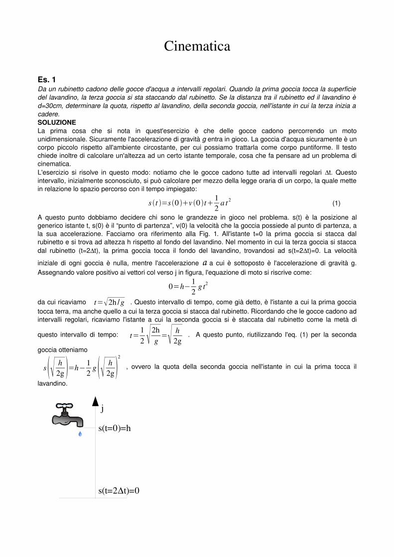
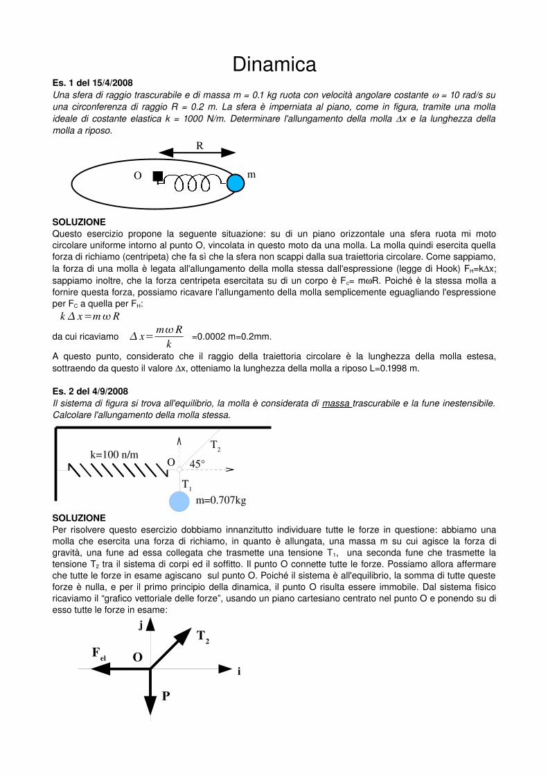
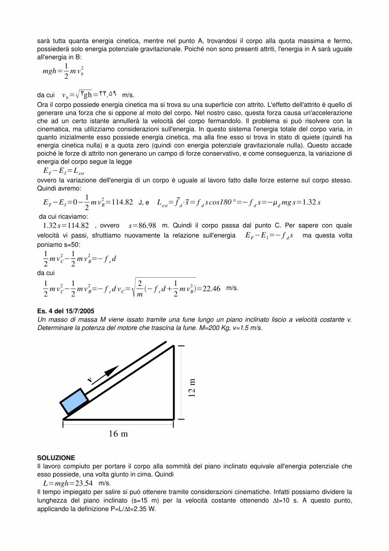
ESERCIZI SVOLTI DI MECCANICA Questa dispensa si propone di fornire allo studente l'anello di giunzione tra teoria ed esercizio. È difatti noto che i modelli creati dai fisici nel corso dei secoli al fine di spiegare i fenomeni naturali si adattino poi alla soluzione di semplici fenomeni reali. Laddove quindi si parla di una goccia che cade da un rubinetto, possiamo pensare ad un corpo puntiforme che si muove di moto rettilineo uniformemente accelerato, oppure, riferendoci ad un oggetto che scivola sul ghiaccio, possiamo pensare ad una superficie ideale senza attrito. L'utilizzo di questa dispensa quindi è finalizzato innanzitutto alla comprensione del testo di un esercizio, passaggio spesso sottovalutato dagli studenti ma di importanza fondamentale (consiglio sempre di leggere il testo di un esercizio per almeno 5 volte! Infatti in questo modo riusciamo ad avere un quadro completo della situazione fisica), quindi all'inserimento del fenomeno descritto all'interno di un problema specifico: grandezze cinematiche, dinamiche, corpo esteso, equilibrio..., ed infine all'applicazione del modello corretto con relativi calcoli matematici. Una verifica che suggerisco di svolgere, qualora non ci si ricordi di una formula, è quella delle unità di misura. Difatti se le unità di misura ai due membri di un'equazione sono differenti, sicuramente l'equazione è sbagliata. La dispensa fornisce alcuni esercizi, tratti da i più recenti temi d'esame, relativi agli argomenti trattati nel corso e la loro dettagliata soluzione. Gli studenti sono pregati, qualora trovassero qualche errore (statisticamente inevitabile), di avvisarmi all'indirizzo email [email protected] Emiliano Puddu
Transcript of TESLA Budget Book – Dictionary...

TESLA Budget Book – Dictionary Version
This tabulation is included here, not to provide any additional cost estimate data beyond what is given in the TESLA TDR, but rather to indicate the extent of the elements considered in preparing the cost estimate. This table was put into a WBS spreadsheet format to facilitate viewing the high level summaries while allowing study of the individual elements. The highest level summary is presented, followed by the expanded listing of the elements considered for each sub-system on subsequent pages. Level 3 Elements TESLA Budget Book - Dictionary Version (w/Fermilab WBS) March 2001 - phg - modified 3dec01 cost estimate in M Euros units - year 2000 costs includes only level of costs available in TESLA TDR # units 1. Cost 1.a
cost 1.a.b cost
roll-up roll-up roll-up 1 Total - TESLA Collider + XFEL Increments 3,377 1.1 TESLA Collider - total (not including XFEL) 3,136 1.1.1 Main Linac Modules 1,131 1.1.2 Main Linac RF System 587 1.1.3 Tunnel & Buildings 546 1.1.4 Machine Infrastructure 336 1.1.5 Damping Rings 215 1.1.6 Auxiliary Systems 124 1.1.7 Beam Delivery System 101 1.1.8 Injection System 97 1.2 XFEL Increments - total 241 1.2.1 XFEL Increments 241
Tesla Engineering Study Review 1 draft 5/8/02 1:45 PM APPENDICES (8may) accessed 1/19/06 4:37 PM
Level 4 Elements TESLA Budget Book - Dictionary Version (w/Fermilab WBS) March 2001 - phg - modified 3dec01 cost estimate in M Euros units - year 2000 costs includes only level of costs available in TESLA TDR # units 1.a.b cost roll-up 1 Total - TESLA Collider + XFEL Increments 1.1 TESLA Collider - total (not including XFEL) 1.1.1 Main Linac Modules 1,131 1.1.1.1 Cavity preparation & string assembly 1.1.1.2 Cryostat modules & sc magnets 1.1.1.3 Cavity structure & vessel fabrication 1.1.1.4 Niobium material RRR 300 1.1.1.5 RF Power & HOM Coupler 1.1.2 Main Linac RF System 587 1.1.2.1 RF Power Distribution & LLRF 1.1.2.2 Klystrons & Interlocks 1.1.2.3 Modulator 1.1.2.4 Pulse transformer & predriver 1.1.2.5 HV pulse cable & installation 1.1.3 Tunnel & Buildings 546 1.1.3.1 Tunnels & access shafts 1.1.3.2 Site & halls & buildings 1.1.3.3 General Tunnel Infrastructure 1.1.4 Machine Infrastructure 336 1.1.4.1 Cryogenic plants & supply 1.1.4.2 Cryogenic Distribution 1.1.4.3 Water plants & distribution 1.1.4.4 AC Power plant & distribution 1.1.4.5 Various supply systems 1.1.5 Damping Rings 215 1.1.5.1 Magnets & Power System 1.1.5.2 Vacuum system 1.1.5.3 RF Power & cavity system 1.1.5.4 Beam diagnostics & controls 1.1.6 Auxiliary Systems 124 1.1.6.1 Global machine control system 1.1.6.2 Electronic & cabling 1.1.6.3 Vacuum RF Power coupler 1.1.6.4 Vacuum modules - Main Linac Cryostats 1.1.6.5 Various auxiliary systems 1.1.7 Beam Delivery System 101 1.1.7.1 Magnets & Power System
Tesla Engineering Study Review 2 draft 5/8/02 1:45 PM APPENDICES (8may) accessed 1/19/06 4:37 PM

1.1.7.2 Beam Stops & cooling 1.1.7.3 Beam diagnostic 1.1.7.4 Vacuum System 1.1.7.5 Fast Kicker & Collimator System 1.1.8 Injection System 97 1.1.8.1 5 GeV Positron Linac & Beamline 1.1.8.2 Positron Source & Injector 1.1.8.3 5 GeV Electron Linac 1.1.8.4 Polarized gun & injector 1.1.8.5 RF Gun & Injector 1.2 XFEL Increments - total 1.2.1 XFEL Increments 241 1.2.1.1 XFEL Tunnel & buildings 1.2.1.2 XFEL Machine additives 1.2.1.3 XFEL Beam switchyard 1.2.1.4 Linac to XFEL Beam lines
Tesla Engineering Study Review 3 draft 5/8/02 1:45 PM APPENDICES (8may) accessed 1/19/06 4:37 PM

Level 5 Elements TESLA Budget Book - Dictionary Version (w/Fermilab WBS) March 2001 - phg - modified 3dec01 cost estimate in M Euros units - year 2000 costs includes only level of costs available in TESLA TDR # units 1.a.b cost roll-up 1 Total - TESLA Collider + XFEL Increments
1.1 TESLA Collider - total (not including XFEL)
1.1.1 Main Linac Modules 1,131 1.1.1.1 Cavity preparation & string assembly 1.1.1.1.1 cavity preparation & assembly 20,592 1.1.1.2 Cryostat modules & sc magnets 1.1.1.2.1 vacuum vessel & cold mass 1,716 vacuum vessel Cryo supports GHeRP (return pipe) shields 4.5 degree shields 70 degree Cryo pipes Cold mass pre-assembly intermediate transportation Final transportation management 1.1.1.2.2 module intercon beam vacuum 1,716 1.1.1.2.3 magnet package 750 1.1.1.2.4 module instrumentation 1,716 1.1.1.2.5 module interconnection 1,716 1.1.1.3 Cavity structure & vessel fabrication 1.1.1.3.1 Structure machining 20,592 1.1.1.3.2 Tuner mechanics + gear box 20,592 1.1.1.3.3 Titanium vessel, tubes & bellows 20,592 1.1.1.3.4 Tuner motor & electronics 20,592 1.1.1.3.5 Assembly & EB Welding 20,592 1.1.1.3.6 Magnetic shielding Cryoperm 20,592 1.1.1.3.7 Magnetic shielding fabrication 20,592 1.1.1.3.8 Piezo tuner 1.1.1.4 Niobium material RRR 300 1.1.1.4.1 Niobium 300 material 20,592 1.1.1.4.2 Niobium 30 material 20,592 1.1.1.4.3 NbTi flange material 20,592 1.1.1.5 RF Power & HOM Coupler 1.1.1.5.1 RF power coupler fabrication 20,592 1.1.1.5.2 Cavity control inside 20,592
Tesla Engineering Study Review 4 draft 5/8/02 1:45 PM APPENDICES (8may) accessed 1/19/06 4:37 PM
1.1.2 Main Linac RF System 587 1.1.2.1 RF Power Distribution & LLRF 1.1.2.1.1 RF Power Distribution 572 RF power circulators RF power hybrid couplers RF wave guides RF transformers RF bellows RF signal couplers 1.1.2.1.2 Low Level RF Control 572 LLC digital feedback LLC monitoring LLC RF components LLC miscellaneous LLC master oscillator & distribution 1.1.2.1.3 (blank) 1.1.2.2 Klystrons & Interlocks 1.1.2.2.1 Klystron, solenoid & socket 572 1.1.2.2.2 Klystron interlocks 572 1.1.2.2.3 Klys, aux. PS Fil, Sol, Bias, Vac. 572 1.1.2.2.4 (blank) 1.1.2.3 Modulator 1.1.2.3.1 Modulator pulser unit 572 Pulse transformer assembly HV power supply Control/interlock Switch assembly Crowbar system Capacitor banks Bouncer system Supports, cooling, & ventilation Under shoot circuit Local subsystem control Miscellaneous 1.1.2.3.2 Modulator interlock 572 1.1.2.4 Pulse transformer & predriver 1.1.2.4.1 Pulse trans. Unit (incl.fil & container) 572 1.1.2.4.2 Cavity interlock 572 1.1.2.4.3 Tunnel cable connections 572 1.1.2.4.4 PreDriver 1.1.2.5 HV pulse cable & installation 1.1.2.5.1 Pulse power cables 572 1.1.2.5.2 Pulse cable installation 572
Tesla Engineering Study Review 5 draft 5/8/02 1:45 PM APPENDICES (8may) accessed 1/19/06 4:37 PM

1.1.3 Tunnel & Buildings 546 1.1.3.1 Tunnels & access shafts 1.1.3.1.1 Main Linac 33,500 1.1.3.1.2 Damping ring 4,000 1.1.3.1.3 Access shaft unit 19 1.1.3.1.4 Bypass Tunnel positrons 600 1.1.3.1.5 Engineering costs 1.1.3.2 Site & halls & buildings 1.1.3.2.1 Site ground 800,000 1.1.3.2.2 HEP experimental Hall 61,500 1.1.3.2.3 Site infrastructure - aux halls 8 1.1.3.2.4 Refrigerator halls 170,520 1.1.3.2.5 HE dump halls 20,000 1.1.3.2.6 Cryo Module Test Facility Hall 134,460 1.1.3.2.7 RF Modulator & Water Plant Halls 113,680 1.1.3.2.8 Engineering costs 1.1.3.3 General Tunnel Infrastructure 1.1.3.3.1 Monorail 34,000 1.1.3.3.2 Traffic lane 37,620 1.1.3.3.3 Fire safety system 40,000 1.1.3.3.4 Module supports 3,500 1.1.3.3.5 Electronic shielding 8,237 1.1.3.3.6 Handy lossy cable 40,000 1.1.4 Machine Infrastructure 336 1.1.4.1 Cryogenic plants & supply 1.1.4.1.1 Cold boxes 1.1.4.1.2 Compressors 1.1.4.1.3 Distribution boxes 3,4,5,7 1.1.4.1.4 Cold compressors 1.1.4.1.5 Distributions boxes 1,6 1.1.4.1.6 Purification 1.1.4.1.7 Controls 1.1.4.1.8 Liquid Helium storage 1.1.4.1.9 Warm gas storage 1.1.4.1.10 Distribution box 2 1.1.4.1.11 Helium 1.1.4.1.12 Miscellaneous 1.1.4.1.13 Budget value to XFEL Incrementals 1.1.4.2 Cryogenic Distribution 1.1.4.2.1 Warm Helium gas tube (DN200) 1.1.4.2.2 Transfer lines 1.1.4.2.3 Vacuum Barriers 1.1.4.2.4 Feed boxes 1.1.4.2.5 End boxes 1.1.4.2.6 Injection feed boxes 1.1.4.2.7 Damping ring RF feed boxes 1.1.4.2.8 Controls 1.1.4.2.9 Booster 1.1.4.2.10 Injection distribution box
Tesla Engineering Study Review 6 draft 5/8/02 1:45 PM APPENDICES (8may) accessed 1/19/06 4:37 PM
1.1.4.3 Water plants & distribution 1.1.4.3.1 Water auxiliary halls 1.1.4.3.2 Water tunnels 1.1.4.3.3 Water XFEL 1.1.4.3.4 Water Experiments 1.1.4.4 AC Power plant & distribution 1.1.4.4.1 Low Voltage AC Power distribution 1.1.4.4.2 High Voltage AC Power plant 1.1.4.4.3 20 KV AC power switchyard stations 1.1.4.4.4 Wall plug power 1.1.4.4.5 Low Voltage AC Power stations 1.1.4.5 Various supply systems 1.1.4.5.1 Main LINC segment ventilation 8 1.1.4.5.2 Auxiliary Hall ventilation 8 1.1.4.5.3 Main Linac first station ventilation 2 1.1.4.5.4 HEP Experimental hall ventilation 1 1.1.4.5.5 Damping Ring Infrastructure 1.1.4.5.6 Cryo Test facility cryogenics 1.1.4.5.7 RF Power test facility 1.1.4.5.8 Cryo test facility operation 1.1.4.5.9 Cryo test RF Power System 1.1.4.5.10 Cryo test control system 1.1.4.5.11 Cryo-connection to HERA cryo-plant 1.1.4.5.12 Cryo test vacuum 1.1.4.5.13 Cryo Test vertical dewar RF
Tesla Engineering Study Review 7 draft 5/8/02 1:45 PM APPENDICES (8may) accessed 1/19/06 4:37 PM

1.1.5 Damping Rings 215 1.1.5.1 Magnets & Power System 1.1.5.1.1 Special Magnets - Wigglers 1.1.5.1.2 Quadrupoles for Damping Ring 1.1.5.1.3 Dipoles for Damping Ring 1.1.5.1.4 Injection/Extraction Sections 1.1.5.1.5 Sextupoles for Damping Ring 1.1.5.1.6 Magnet assembly 1.1.5.1.7 Solenoids B-line & Bunch Compressor 1.1.5.1.8 Magnetic measurements 1.1.5.1.9 Correctors for Damping Ring 1.1.5.1.10 Quadrupoles for Beamline & B.C. 1.1.5.1.11 multipole girders/supports 1.1.5.1.12 Power supply system 1.1.5.1.13 Dipoles for Beamline and B.C. 1.1.5.1.14 Dipole stands and supports 1.1.5.1.15 Correctors for Beamline & B.C. 1.1.5.1.16 Sextupoles for Beamline & B.C. 1.1.5.2 Vacuum system 1.1.5.1.1 Pumps and power supplies 1.1.5.1.2 Damping Ring Vacuum Chamber 1.1.5.1.3 Vacuum chamber supports 1.1.5.1.4 Manual & auto valves 1.1.5.3 RF Power & cavity system 1.1.5.3.1 RF Cryo-modules 1.1.5.3.2 RF Power sources 1.1.5.3.3 Waveguide network system 1.1.5.3.4 Cryogenic system 1.1.5.3.5 Cooling system 1.1.5.3.6 Electronics, controls, interlocks, etc. 1.1.5.4 Beam diagnostics & controls 1.1.5.4.1 BPM button/strip line monitors 1.1.5.4.2 Beam diagnostics electronics 1.1.5.4.3 Toroidal current transformers 1.1.5.4.4 Wall current monitors 1.1.5.4.5 Emittance measurement system 1.1.5.4.6 Tune monitors 1.1.5.4.7 Beam loss monitors 1.1.5.4.8 Fluorescent screens 1.1.5.4.9 Scrapers 1.1.5.4.10 DC current transformers
Tesla Engineering Study Review 8 draft 5/8/02 1:45 PM APPENDICES (8may) accessed 1/19/06 4:37 PM

1.1.6 Auxiliary Systems 124 1.1.6.1 Global machine control system 1.1.6.1.1 Electronics racks, etc 700 1.1.6.1.2 Crates, front-end servers 700 1.1.6.1.3 Control room equipment 100 1.1.6.1.4 Network equipment 800 1.1.6.1.5 Expendable Materials 300 1.1.6.1.6 Network cables 500 1.1.6.1.7 Alarm interface modules 60 1.1.6.1.8 Servers & consoles 300 1.1.6.1.9 Alarm line cables 60 1.1.6.2 Electronic & cabling 1.1.6.2.1 Data acquisition 900 1.1.6.2.2 Monitor electronics Main Linac 800 1.1.6.2.3 Beam loss Main Linac 800 1.1.6.2.4 Beam monitors Main Linac 800 1.1.6.2.5 Monitor electronics general 500 1.1.6.2.6 Commercial electronics 100 1.1.6.2.7 Monitor beam lines 100 1.1.6.2.8 Miscellaneous items 1.1.6.3 Vacuum RF Power coupler 1.1.6.3.1 Pump tube d=100 1.1.6.3.2 Sputter pump - 60 l/sec 1.1.6.3.3 Titanium sublimation pump 1.1.6.3.4 Sputter pump power supplies 1.1.6.3.5 TSP power supplies 1.1.6.3.6 Manual valve ID 35 1.1.6.3.7 Vacuum component electronics 1.1.6.3.8 Bellows 1.1.6.3.9 Pump pots 1.1.6.4 Vacuum modules - Main Linac Cryostats 1.1.6.4.1 Penning filaments 1.1.6.4.2 Pump stations 1.1.6.4.3 Manual vacuum valve ID 100 1.1.6.4.4 Vacuum installation tools cryostats 1.1.6.4.5 Vacuum component electronics 1.1.6.4.6 Bridge valves 1.1.6.4.7 Pirani filaments 1.1.6.5 Various auxiliary systems 1.1.6.5.1 DC power supplies Main Linac 1.1.6.5.2 Spare linac modules 1.1.6.5.3 Alignment & Survey 1.1.6.5.4 Cables from general store 1.1.6.5.5 Connectors from general store 1.1.6.5.6 Main Linac beam vacuum control 1.1.6.5.7 Radiation safety interlock system
Tesla Engineering Study Review 9 draft 5/8/02 1:45 PM APPENDICES (8may) accessed 1/19/06 4:37 PM
1.1.7 Beam Delivery System 101 1.1.7.1 Magnets & Power System 1.1.7.1.1 Magnet Supplies & Cables 1.1.7.1.2 Quadrupoles 180 1.1.7.1.3 Main Dipoles 370 1.1.7.1.4 Electrostatic Separators 32 1.1.7.1.5 SC Doublets 2 1.1.7.1.6 Sextupoles & Octupoles 26 1.1.7.1.7 Movers 206 1.1.7.1.8 Emergency extraction quads 22 1.1.7.1.9 Emergency extraction dipoles 12 1.1.7.1.10 Supports 624 1.1.7.1.11 H/V correctors 400 1.1.7.1.12 Main extraction quadrupoles 6 1.1.7.1.13 Main extraction dipoles 4 1.1.7.1.14 Main extraction septum 2 1.1.7.1.15 Emergency extraction septum 2 1.1.7.2 Beam Stops & cooling 1.1.7.2.1 Cooling system 2 1.1.7.2.2 Fast extraction, 30 kicker, 1 m long 2 1.1.7.2.3 Fast sweep 4 1.1.7.2.4 Water vessel 6 1.1.7.3 Beam diagnostic 1.1.7.3.1 Laser profile 2 1.1.7.3.2 Beam electronics 370 1.1.7.3.3 Final Focus Monitor 2 1.1.7.3.4 BPM 200 1.1.7.3.5 Beam loss monitor 370 1.1.7.3.6 Wire scanner 16 1.1.7.3.7 Cables & connectors 370 1.1.7.4 Vacuum System 1.1.7.4.1 Copper surfacing 1,800 1.1.7.4.2 Vacuum tubes 3,400 1.1.7.4.3 Pumps & valves 200 1.1.7.4.4 Electronics 200 1.1.7.4.5 Vacuum utilities 200 1.1.7.5 Fast Kicker & Collimator System 1.1.7.5.1 Spoiler 26 1.1.7.5.2 Spoiler cooling water unit 26 1.1.7.5.3 Absorber 12 1.1.7.5.4 Absorber cooling water circuit 12 1.1.7.5.5 Instrumentation 2 1.1.7.5.6 General cables & connectors 3,400 1.1.7.5.7 Fast Kickers 16 1.1.7.5.8 Magnet mover electronics & cables 206 1.1.7.5.9 BPM 10 1.1.7.5.10 Electronics 1 1.1.7.5.11 Miscellaneous
Tesla Engineering Study Review 10 draft 5/8/02 1:45 PM APPENDICES (8may) accessed 1/19/06 4:37 PM

1.1.8 Injection System 97 1.1.8.1 5 GeV Positron Linac & Beamline 1.1.8.1.1 Cryogenic modules 1.1.8.1.2 RF power system 1.1.8.1.3 Accelerating system 1.1.8.1.4 Magnet elements 1.1.8.1.5 Beam Line Magnets 1.1.8.1.6 Beam Line Vacuum system 1.1.8.1.7 Beam Line Instrumentation 1.1.8.1.8 Vacuum 1.1.8.1.9 Instrumentation 1.1.8.1.10 Beam Line DC power supplies 1.1.8.2 Positron Source & Injector 1.1.8.2.1 RF power system 1.1.8.2.2 100 m long undulator (all included) 1.1.8.2.3 Accelerating system 1.1.8.2.4 Target & pulsed magnet (x2) 1.1.8.2.5 Magnets 1.1.8.2.6 Beam Line vacuum 1.1.8.2.7 DC power supplies 1.1.8.2.8 Instrumentation 1.1.8.2.9 Pumps, bellows & valves 1.1.8.3 5 GeV Electron Linac 1.1.8.3.1 Cryo Modules 1.1.8.3.2 Klystrons & Modulators 1.1.8.3.3 Power supplies 1.1.8.3.4 Vacuum 1.1.8.3.5 Magnet packages 1.1.8.4 Polarized gun & injector 1.1.8.4.1 Room temperature Linac 1.1.8.4.2 SC Linac to 500 MeV 1.1.8.4.3 Load-lock system 1.1.8.4.4 Electron gun 1.1.8.4.5 Pre-bunching section 1.1.8.4.6 Matching & analysis line 1.1.8.5 RF Gun & Injector 1.1.8.5.1 Equipped cryostat modules 1.1.8.5.2 RF, vacuum & diagnostics 1.1.8.5.3 10 MW Klystron & modulators 1.1.8.5.4 Klystron & modulator (4.5 MW) 1.1.8.5.5 Laser
Tesla Engineering Study Review 11 draft 5/8/02 1:45 PM APPENDICES (8may) accessed 1/19/06 4:37 PM

1.2 XFEL Increments - total 1.2.1 XFEL Increments 241 1.2.1.1 XFEL Tunnel & buildings 1.2.1.1 XFEL Experimental hall 150,000 1.2.1.2 XFEL dump halls 24,000 1.2.1.3 XFEL tunnels 8,000 1.2.1.4 XFEL tunnel infrastructure 8,000 1.2.1.2 XFEL Machine additives 1.2.2.1 Additional air conditioning 1.2.2.2 Radiation safety design & interlocks 1.2.2.3 XFEL Gun & Injector 1.2.2.3.1 Equipped cryostat modules 1.2.2.3.2 2x10 MW klystron/modulator assmbl. 1.2.2.3.3 Bunch compressors 1.2.2.3.4 Laser 1.2.2.3.5 3rd harmonic accel. cavity/coupler 1.2.2.3.6 Power supplies 1.2.2.3.7 Preparation chamber (mech&vac) 1.2.2.3.8 Vacuum & Diagnostics 1.2.2.4 Additional water plant & distribution 1.2.2.5 Compressor cavities 120 1.2.2.6 Compressor RF power system 3 1.2.2.7 Cryogenic distribution additives 1.2.2.8 Wave guide absorber adds 2,052 1.2.2.9 Power supply RF modulator adds 57 1.2.2.10 Substation racks & electronics 50 1.2.2.11 Ten Degree bend for XFEL 1.2.2.12 XFEL Bunch compressor 2 & 3 1.2.2.13 Compressor cryostat module 10 1.2.1.3 XFEL Beam switchyard 1.2.3.1 XFEL beam dump components 1.2.3.2 Dipole magnets 295 1.2.3.3 Quadrupole magnets 537 1.2.3.4 Sextupole Magnets 284 1.2.3.5 Pulsed dipole magnets 6 1.2.3.6 Correction magnets 120 1.2.3.7 Octupole magnets 16 1.2.3.8 Power supplies & cables 1.2.3.9 Beam diagnostic & feedbacks 1.2.3.10 Vacuum System 1.2.3.11 Cable, connectors & mechanics 1.2.1.4 Linac to XFEL Beam lines 1.2.4.1 Magnets 1.2.4.2 Power supplies & cables 1.2.4.3 Vacuum per meter 1.2.4.4 Beam position monitors
Tesla Engineering Study Review 12 draft 5/8/02 1:45 PM APPENDICES (8may) accessed 1/19/06 4:37 PM

Element Descriptions for TESLA Conventional Construction and Infrastructure
WBS Dictionary for 1.1.3 Tunnels and Buildings and 1.1.4 Machine Infrastructure Introduction:
The following descriptions were developed based on general discussions during my visit to the DESY Laboratory. The intent is to create an understanding of the content of the TESLA Budget Book, specifically for the Conventional Facilities that will be provided as part of the TESLA project. A brief discussion of various aspects of the project scope and comments on the cost estimating process are included in the main body of this report.
Work Breakdown Structure (WBS) category numbers, corresponding to elements or entries in the TESLA Budget Book, were attached by Fermilab. This was both to more nearly match customary U.S. formats and to facilitate cross-referencing.
The buildings and tunnel enclosures are identified in TESLA WBS 1.1.3, “Tunnel and Buildings”. However, additional items that are considered, from the Fermilab perspective, to be part of “Conventional Facilities” are also contained in TESLA WBS 1.1.4, “Machine Infrastructure” and are identified by element number below.
Note that there are some inconsistencies in the sizes of the surface buildings
between the TDR, the TESLA Budget Book, and the schematic table presented at Snowmass in July, 2002.
1.1.3 Tunnel & Buildings
1.1.3.1 Tunnels and Access Shafts
1.1.3.1.1 Main Linac- This is the Main Linac enclosure. It consists of a bored tunnel, fully lined with precast concrete “tubbings”. Due to construction below sea level, the tunnel will constructed using a shielded tunnel boring machine incorporating a pressurized cutting head to eliminate water infiltration and a recycled bentonite slurry for the removal of excavated material. This enclosure is 33 km in length and has an inside finished diameter of 5.2 m. Grouting behind the precast concrete is included and will be accomplished as part of the precast liner installation. This tunnel is intended to be constructed as part of a design/build project with the design costs included in the per lineal meter unit cost. This unit cost was developed based on the actual tunnel costs incurred during the construction of the HERA project. The finished tunnel will consist of the interior surface of the precast lining with no provision for lighting,
Tesla Engineering Study Review 13 draft 5/8/02 1:45 PM APPENDICES (8may) accessed 1/19/06 4:37 PM

HVAC, electrical distribution, monorail or other interior finishes. (These are included in the 1.1.4 Machine Infrastructure section.)
1.1.3.1.2 Damping Ring - These are four “loops” connected to the Main Linac
enclosure. Like the Main Linac, these “loops” consist of a bored tunnel, fully lined with precast concrete “tubbings”. Due to construction below sea level, the tunnel will constructed using a shielded tunnel boring machine incorporating a pressurized cutting head to eliminate water infiltration and a recycled bentonite slurry for the removal of excavated material. These enclosures total 4 km in length and have an inside finished diameter of 3 m. Grouting behind the precast concrete is included and will be accomplished as part of the precast liner installation. This tunnel is intended to be constructed as part of a design/build project with the design costs included in the per meter unit cost. This unit cost was developed based on the actual tunnel costs incurred during the construction of the HERA project. The finished tunnel will consist of the interior surface of the precast lining with no provision for lighting, HVAC, electrical distribution, monorail or other interior finishes. (These are included in the 1.1.4 Machine Infrastructure section.)
1.1.3.1.3 Access Shafts – There are nineteen access shafts included in the TESLA
conventional construction of which eleven are permanent shafts and eight are considered temporary for the facilitation of construction activities and will be filled in with no surface access at the completion of construction. These shafts are nominally 15 m in finished diameter, and range from 20 m to 30 m in depth. They are to be concrete structures, either cast-in-place or precast lined depending on the final contracted design. In the estimate, a single average unit cost per shaft has been assigned. These shafts are intended to be constructed as part of a design/build project with the design costs included in the unit cost per shaft. The shafts were sized at 15 meters, but new cryomodules are planned to be 17 meters long, requiring larger access shafts to prevent having to tip the cryomodules during installation.
1.1.3.1.4 Positron By-pass Tunnel - This is the enclosure that allows the positron
beam to by-pass the interaction region and be transported into the positron Main Linac tunnel. It consists of a bored tunnel, fully lined with precast concrete “tubbings”. Due to construction below sea level, the tunnel will constructed using a shielded tunnel boring machine incorporating a pressurized cutting head to eliminate water infiltration and a recycled bentonite slurry for the removal of excavated material. This enclosure is 600 m in length and has an inside finished diameter of 3 m. Grouting behind the precast concrete is included and will be accomplished as part of the precast liner installation. This tunnel is intended to be constructed as part of a design/build project with the design costs included in the per meter unit cost. This unit cost was
Tesla Engineering Study Review 14 draft 5/8/02 1:45 PM APPENDICES (8may) accessed 1/19/06 4:37 PM

developed based on the actual tunnel costs incurred during the construction of the HERA project. The finished tunnel will consist of the interior surface of the precast lining with no provision for lighting, HVAC, electrical distribution, monorail or other interior finishes. (These are included in the 1.1.4 Machine Infrastructure section.)
1.1.3.1.5 Engineering Costs – This element includes the costs for contracted A/E
and Construction Management support of 1.1.3.1, Tunnels and Buildings, that is not included in the design/build descriptions indicated above and specifically excludes any additional operational or engineering support from existing DESY personnel.
1.1.3.2 Site and Halls and Buildings
1.1.3.2.1 Site Ground – This element provides for the acquisition of surface land
required for the construction of the TESLA project beyond the existing DESY site. Specifically it provides land for the construction of the permanent access shafts and surface buildings at the six cryogenic plant sites distributed along the length of the TESLA tunnel beyond the existing DESY site. Each of these six sites requires approximately 40,000 m2 (10 acres). This element also includes the land needed for the central area, which includes the interaction hall and beam dumps as well as the land required for the XFEL. The central site requires approximately 540,000 m2 (135 acres). The value assigned to this element is based on a prevailing land cost per m2. This per m2 cost includes a nominal provision for connecting to local natural gas, domestic water and sanitary sewer service if available. If these utilities are not locally available, propane, local water wells and sanitary holding tanks or portable toilet facilities will be considered.
1.1.3.2.2 HEP Experimental Hall – This is the single, below ground interaction
region hall. The hall will be constructed of cast-in-place concrete and is modeled after the experimental halls provided for the HERA project. The experimental hall measures 82 m x 32 m in plan with a ceiling height of 23 m. This provides a total estimated volume of 61,500 m3. The price for this element is based on a unit cost per m3 and is primarily based on the construction experience gained from the HERA project. This hall is intended to be constructed as part of a design/build project with the design costs included in the per m3 unit cost. The finished hall will consist of the interior surface of the cast-in-place concrete with no provision for lighting, HVAC, electrical distribution or other interior finishes.
1.1.3.2.3 Site Infrastructure Auxiliary Halls – This element provides additional
local infrastructure support for the seven cryogenic halls and access shafts as well as the single access hall and shaft at the far end of the
Tesla Engineering Study Review 15 draft 5/8/02 1:45 PM APPENDICES (8may) accessed 1/19/06 4:37 PM

positron Main Linac at Westerhorn. The cost for this element is applied as a lump sum per hall.
1.1.3.2.4 Refrigerator Halls – This element describes the seven surface buildings
that enclose the cryogenic equipment and access shafts to the tunnel enclosure below. Each building measures 85 m x 32 m in plan with a ceiling height of 10 m. This provides a total estimated volume of 24,360 m3 per building. While general lighting and power distribution is included in this cost, there is no provision for HVAC with respect to comfort cooling or heating in the base cost. It is intended that rejected heat will be utilized to meet winter heating needs. These buildings are intended to be constructed as part of a design/build project with the design costs included in the per m3 unit cost.
1.1.3.2.5 High Energy Dump Halls – These are the two below ground halls that
will enclose the electron and positron dumps adjacent to the experimental hall. They will be constructed of cast-in-place concrete and is modeled after the experimental halls provided for the HERA project. Each dump enclosure measures 30 m x 25 m in plan with a ceiling height of 15 m. This provides a total estimated volume of 11,250 m3 for each enclosure. The price for this element is based on a unit cost per m3 and is primarily based on the construction experience gained from the HERA project. These enclosures are intended to be constructed as part of a design/build project with the design costs included in the per m3 unit cost. The finished hall will consist of the interior surface of the cast-in-place concrete with no provision for lighting, HVAC, electrical distribution or other interior finishes.
1.1.3.2.6 Cryo Module Test Facility Hall – This is a single surface building
which will house the equipment needed to test the completed cryogenic modules prior to final installation. It measures 135 m x 85 m with a ceiling height of 12 m. This provides a total estimated volume of 137,700 m3. While general lighting and power distribution is included in this cost, there is no provision for HVAC with respect to comfort cooling or heating in the base cost. It is intended that rejected heat will be utilized to meet winter heating needs. These buildings are intended to be constructed as part of a design/build project with the design costs included in the per m3 unit cost.
1.1.3.2.7 RF Modulator and Water Plant Halls - This element describes the
even surface buildings that enclose equipment required for the cooling needs of the non-cryogenic portions of the TESLA machine. These buildings will be constructed in conjunction with the Refrigerator Halls described above and measure 35 m x 35 m in plan with a ceiling height of 5 m. This provides a total estimated volume of 6,125 m3 per building. While general lighting and power distribution is included in this cost,
Tesla Engineering Study Review 16 draft 5/8/02 1:45 PM APPENDICES (8may) accessed 1/19/06 4:37 PM

there is no provision for HVAC with respect to comfort cooling or heating in the base cost. It is intended that rejected heat will be utilized to meet winter heating needs. These buildings are intended to be constructed as part of a design/build project with the design costs included in the per m3 unit cost. (Note added, May, 2002: the RF modulator requirements per location are for three floors, each of 1,480 m2 area. This is to be added to the 232 m2 requirement for the water plant as in the TDR.)
1.1.3.2.8 Engineering Cost - This element includes the costs for contracted A/E
and Construction Management support of 1.1.3.2, Site and Halls and Buildings, that is not included in the design/build descriptions indicated above and specifically excludes any additional operational or engineering support from existing DESY personnel.
1.1.3.3 General Tunnel Infrastructure
1.1.3.3.1 Monorail – This monorail system runs the entire length of the machine enclosure. It provides the means for personnel and material transport as well as consideration for emergency use. The cost is based on a unit amount per lineal meter of tunnel enclosure including installation and was developed directly by the monorail manufacturer.
1.1.3.3.2 Traffic Lane – This element provides the traffic lane structure within the
Main Linac and damping ring enclosures. It consists of a steel platform built over the distribution cables installed for high voltage and pulse power. It provides for personnel access along the length of the enclosures. The cost is based on a unit amount per lineal meter of tunnel enclosure.
1.1.3.3.3 Fire Safety System – A unit amount per lineal meter of tunnel in
included in the estimate to address fire safety issues. It is intended that this system will include a full detection system with only localized suppression and some consideration for remote fire fighting capability with the monorail trains.
1.1.3.3.4 Module Supports – This element provides the support stands for the
fully assembled machine modules. They are considered structural supports and therefore part of the conventional construction. The cost is based on a per unit amount that includes both manufacture and installation.
1.1.3.3.5 Electronic Shielding – This element provides for localized radiation
shielding of sensitive electronic equipment at various locations along the length of the tunnel. Its cost is based on a unit amount per lineal meter of tunnel enclosure as required.
Tesla Engineering Study Review 17 draft 5/8/02 1:45 PM APPENDICES (8may) accessed 1/19/06 4:37 PM

1.1.3.3.6 Handy Lossy Cable – This element provides for basic communication
needs throughout the underground enclosures. The cost is based on a unit amount per lineal meter of tunnel enclosure.
1.1.4 Machine Infrastructure
1.1.4.3 Water Plants and Distribution
1.1.4.3.1 Water in Auxiliary Halls – This element provides the equipment and water source needed at each surface Refrigerator Hall for the cooling water system. It includes required chillers, pumping equipment and piping as well as the drilling of a water well if local domestic water is not available.
1.1.4.3.2 Water in Tunnels – This element provides the equipment needed with
the tunnel enclosures for the cooling water system. 1.1.4.3.3 Water at XFEL – This element provided the equipment needed for the
XFEL facility requirements for cooling water. 1.1.4.3.4 Water at Experimental Area – This element provides the equipment
and water source needed specifically for the cooling water system required at the interaction region. It includes the required chillers, pumping equipment and piping as well as the drilling of a water well if local domestic water is not available.
Elements 1.1.4.3.1 through 1.1.4.3.4 were discussed as a single system and only a total estimated cost for the entire system was indicated.
1.1.4.4 AC Power Plant and Distribution
1.1.4.4.1 Low Voltage AC Power Distribution – This element provides for the
installation of all material and equipment needed for power distribution at the 400 V level for all structures and enclosures both above and below ground.
1.1.4.4.2 High Voltage AC Power Plant – This element provides for the
installation of all material and equipment needed for the eight individual connections to local main power distribution supply lines located at each of the cryogenic Refrigerator Halls.
Tesla Engineering Study Review 18 draft 5/8/02 1:45 PM APPENDICES (8may) accessed 1/19/06 4:37 PM

1.1.4.4.3 20 KV AC Power Switchyard Stations – This element provides for the installation of all material and equipment needed for the eight individual substations required to transform available local line power to distribution at the 20 KV level.
1.1.4.4.4 Wall Plug Power - This element provides for the installation of all
material and equipment needed for wall plug power distribution in all structures and enclosures both above and below ground.
1.1.4.4.5 Low Voltage Power Stations - This element provides for the
installation of all material and equipment needed at the eight individual substations required to transform secondary power from the 20 KV level to the 400 V level.
Elements 1.1.4.4.1 through 1.1.4.4.5 were discussed as a single system and only a total estimated cost for the entire system was indicated.
1.1.4.5 Various Supply Systems
1.1.4.5.1 Main Linac Segment Ventilation – This element provides for the
installation of all material and equipment needed to meet the ventilation requirements of the Main Linac enclosures with equipment located at each of the cryogenic Refrigerator Halls.
1.1.4.5.2 Auxiliary Hall Ventilation - This element provides for the installation
of all material and equipment needed to meet the ventilation requirements of the surface level cryogenic Refrigerator Halls.
1.1.4.5.3 Main Linac First Station Ventilation - This element provides for the
installation of all material and equipment needed to meet the ventilation requirements at the start of each Main Linac enclosure with equipment located at each respective access shaft.
1.1.4.5.4 HEP Experimental Hall Ventilation - This element provides for the
installation of all material and equipment needed to meet the ventilation requirements at the interaction region.
1.1.4.5.5 Damping Ring Infrastructure - This element provides for the
installation of all material and equipment needed to meet the ventilation requirements at the damping ring enclosures with equipment located at each respective access shaft.
Elements 1.1.4.5.1 through 1.1.4.5.5 were discussed as a single system and only a total estimated cost for the entire system was indicated.
Tesla Engineering Study Review 19 draft 5/8/02 1:45 PM APPENDICES (8may) accessed 1/19/06 4:37 PM


![[Tesla Nickola] the Strange Life of Nikola Tesla(BookFi.org)](https://static.fdocuments.us/doc/165x107/55cf9cb0550346d033aab3ce/tesla-nickola-the-strange-life-of-nikola-teslabookfiorg.jpg)