terrestrialization in Hangzhou,...
42
Modelling the engineering behaviour of fibrous peat formed due to rapid anthropogenic 1 terrestrialization in Hangzhou, China 2 3 Z.X. Yang 1 , C.F. Zhao 2 , C.J. Xu 3 , S.P. Wilkinson 4 , Y.Q. Cai 5 , K. Pan 6 4 Abstract 5 Peat is a very variable but normally weak material. While engineering failures involving peat 6 are common, the full diversity of engineering behaviours exhibited by peat have not been 7 well classified due to the large range of possible compositions of peats. A laboratory study 8 carried out on the peat at Jiangyangfan Eco-park, located in Hangzhou, China identify it as 9 displaying an intermediate engineering response compared to the ranges normally observed 10 for peat. The peat is a fill (made ground) originating from dredging of the West Lake, a site of 11 cultural and historic importance in China. Given its relatively unique mechanism of 12 deposition the distinctive characteristics of this peat are presented in comparison to other 13 peats reported in the literature highlighting its intermediate nature. The shearing behaviour 14 of peat can be described using the framework of critical state theory. The most prominent 15 characteristic of the West Lake Peat is that plastic deformation occurs at very small stress 16 levels. A constitutive model based on critical state theory for predicting the undrained shear 17 behaviour of this type of peat from low stress to critical state level is presented. This model 18 also includes several elements of peat behaviour previously reported and it may therefore 19 1 Professor, Dept. of Civil Engineering, Zhejiang University, China, [email protected] 2 Former postgraduate student, Dept. of Civil Engineering, Zhejiang University, China, [email protected]; currently Ph.D student at Ecole Centrale de Nantes, France 3 Professor, Dept. of Civil Engineering, Zhejiang University, China, [email protected] 4 Senior Lecturer, Department of Civil Engineering, University of Wolverhampton, Wulfruna Street, WV1 1LY, UK, [email protected] 5 Professor, Department of Civil Engineering, Zhejiang University, [email protected] 6 Postgraduate student, Dept. of Civil Engineering, Zhejiang University, China, [email protected]
Transcript of terrestrialization in Hangzhou,...

Modelling the engineering behaviour of fibrous peat formed due to rapid anthropogenic 1
terrestrialization in Hangzhou, China 2
3
Z.X. Yang1, C.F. Zhao2, C.J. Xu3, S.P. Wilkinson4, Y.Q. Cai5, K. Pan6 4
Abstract 5
Peat is a very variable but normally weak material. While engineering failures involving peat 6
are common, the full diversity of engineering behaviours exhibited by peat have not been 7
well classified due to the large range of possible compositions of peats. A laboratory study 8
carried out on the peat at Jiangyangfan Eco-park, located in Hangzhou, China identify it as 9
displaying an intermediate engineering response compared to the ranges normally observed 10
for peat. The peat is a fill (made ground) originating from dredging of the West Lake, a site of 11
cultural and historic importance in China. Given its relatively unique mechanism of 12
deposition the distinctive characteristics of this peat are presented in comparison to other 13
peats reported in the literature highlighting its intermediate nature. The shearing behaviour 14
of peat can be described using the framework of critical state theory. The most prominent 15
characteristic of the West Lake Peat is that plastic deformation occurs at very small stress 16
levels. A constitutive model based on critical state theory for predicting the undrained shear 17
behaviour of this type of peat from low stress to critical state level is presented. This model 18
also includes several elements of peat behaviour previously reported and it may therefore 19
1Professor, Dept. of Civil Engineering, Zhejiang University, China, [email protected]
2Former postgraduate student, Dept. of Civil Engineering, Zhejiang University, China, [email protected]; currently
Ph.D student at Ecole Centrale de Nantes, France 3Professor, Dept. of Civil Engineering, Zhejiang University, China, [email protected]
4Senior Lecturer, Department of Civil Engineering, University of Wolverhampton, Wulfruna Street, WV1 1LY, UK,
[email protected] 5Professor, Department of Civil Engineering, Zhejiang University, [email protected]
6Postgraduate student, Dept. of Civil Engineering, Zhejiang University, China, [email protected]

be applied to a wider range of peat soils. 20
Keywords: Peat; physiochemical properties; compression; undrained shear; critical state; 21
constitutive model 22
23
Introduction 24
Peat is the most variable soil type with respect to engineering purposes. It is defined as a 25
predominantly organic soil which accumulates in-situ in a mire (BS 5930, 1999). However 26
peats and peaty soils can develop in a very wide range of geotechnical environments. In 27
addition to organic components, peats can contain the full range of constituents also found 28
in mineral soils depending on the conditions under which the peat has been formed. The 29
organic components of peat can also vary widely in terms of both origin and geotechnical 30
behaviour. In engineering peats are classified as ranging from fibrous peats, where the 31
organic constituents remain largely identifiable, to amorphous peats where the original 32
structure of the organic components have either been lost due to decomposition, or where 33
the peat was originally deposited as a sludge (BS EN ISO 14688-1, 2002). Within this broad 34
spectrum there is a large potential for variation in response to the range of organic 35
components from which the peat is formed. One of the more commonly used classification 36
systems for peat, presented by Hobbs (1986), uses twelve distinct scales for each of twelve 37
peat descriptors. Given all of the possible options within this system, a very large set of 38
unique peat classifications can be generated. While some combinations are unlikely in 39
practice, the term peat still encompasses a substantial range of materials with an equally 40
wide range of engineering behaviours. One of the most important factors controlling the 41

engineering behaviour of peat is the content of organic fibres. Fibres provide tensile strength, 42
and the amount of fibres in a peat is critical for its overall behaviour. 43
Peat is often described in the literature as a very soft and problematic engineering 44
material. Peats often have very high void ration and water content, resulting in very low 45
initial values of bulk density. As a result peats often exhibit high values of compressibility, 46
and are commonly reported as responsible for excessive amounts of observed settlement 47
(Berry and Poskitt 1972, Edil et al 1991, Nichol and Farmer 1998, Mesri and Ajlouni 2007, 48
Kazemian et al 2011, Zhang and O’Kelly 2014). Many geostructures such as slopes, 49
embankments, retaining walls and foundations which have been constructed on peat have 50
experienced damage or stability issues (Mesri and Choi 1985, Long 2005, Kvæ rner and 51
Snilsberg 2008, Zwanenburg et al 2012, Boylan and Long 2014). In the majority of models for 52
simulating peat behaviour effective stress based approaches is commonly used directly 53
(Yamaguchi et al 1985, Long and Jennings 2006, den Haan and Grognet 2014). This approach 54
assumes that soil particles are incompressible. Peats have a high proportion of organic 55
particles which often have high intra-particle water contents. As these particles can 56
compress, deform and change their intra-particle moisture content the assumption of 57
incompressible particles is likely not valid. On this basis the applicability of the effective 58
stress based approach has recently been brought into question (Zhang and O’Kelly 2014). 59
When modelling peat engineering behaviour it is important to simulate its viscous nature 60
including its dependency on deformation rate and its long term deformation capacity. 61
Secondary consolidation in peat is often much more significant than for other geomaterials 62
(Mesri et al 1997, Kramer 2000, Mesri and Ajlouni 2007). In comparison to inorganic/clastic 63

soils, peats commonly display high values of undrained shear strength and much higher 64
effective friction angles (Yamaguchi et al 1985, Long 2005, Cheng et al. 2007, Mesri and 65
Ajlouni 2007, Hendry et al 2012, O’Kelly and Zhang 2013). This is especially true for peats 66
with a reasonably large quantity of constituent fibres or fragmented plant tissues. 67
A wide range of geotechnical materials have been successfully modelled using critical 68
state theory, but very few attempts to characterize peat using this approach have been 69
made. This is likely because samples are not sheared to critical state failure because samples 70
normally undergo tensile failure prior to reaching critical state due to the high frictional 71
strength of peat. However, recently effort has been made to understand peat behaviour 72
within the critical state framework. Boumezerane (2014) adopted a critical state based 73
kinematic model to simulate the unloading/reloading behaviour of peat, and den Han and 74
Feddema (2013) analysed the deformation and strength of embankments on soft Dutch peat 75
using a viscous version of the modified Cam-clay framework. These successes indicate that 76
there is a potential that critical state based approaches could be used to improve the 77
understanding of the engineering behaviour of peats and highly organic mineral soils. The 78
engineering behaviour observed from the peat samples, in addition to the range of 79
previously observed engineering behaviours of peats from across the world indicates the 80
range of behaviours that samples of peat can display. 81
This paper presents a laboratory study of the behaviour of peat obtained from the 82
Jiangyangfan Eco-park (originally dredged from the nearby West Lake) which is a wildlife 83
preserve within the city of Hangzhou, China. The West Lake peat is a fibrous material but 84
with a relatively low number of coarse fibres. A modified constitutive model based on a 85

critical state framework and concepts of dilatancy for simulating the undrained engineering 86
behaviour of this peat during shear failure is presented. Model applicability and accuracy is 87
evaluated by comparison with experimental results for the West Lake Peat sheared under 88
undrained conditions with varying initial consolidation stresses. 89
90
Field site 91
In 2008, the construction of an eco-park was initiated to develop the vacant Jiangyangfan 92
site (Fig. 1), 3km to the south of West Lake (also known as Xihu) near Hangzhou in Zhejiang 93
Province, China, as part of the West Lake Cultural Landscape, which was inscribed on 94
UNESCO’s World Heritage List in 2011. Prior to 1999 the site was the Jiangyangfan reservoir, 95
however it was selected as the repository for materials dredged from the West Lake. The 96
West lake has been dredged by pipeline three times during its history in 1952, 1976 and 97
1999 respectively (Hangzhou local Chronicles compilation committee, 2003). Prior to this 98
date the lake had been dredged many times by hand during its history. In fact the first time 99
the lake is referred to in an official document using its current name West Lake (“Xihu”) was 100
in relation to a request for dredging in the year 1090 by the famous poet Su Shi (1090), the 101
then governor of Hangzhou. This request refers to an even earlier dredging event performed 102
around year 821-824. Dredging of the lake is thus a major element of the local history and 103
culture. Prior to 1952 the lake had reached a very bad state with water depth reduced to 104
about 0.5m due to build-up of organic sludge. Leaves and vegetation had accumulated in the 105
lake along with clay and silt generating a material rich in organic matter at a very high 106
moisture content. It was then decided that the lake would undergo periodic dredging to 107

remove this sludge via temporary pipelines (Shao et al 2007). During the most recent 108
dredging carried out between 1999 and 2003 the sludge was excavated and pumped along 109
an approximately 4km long pipeline between West Lake and Jiangyangfan reservoir. During 110
transportation the sludge was mixed with large volumes of water, and thus its original fabric 111
was completely disrupted. During the four years of dredging approximately 1,000,000 m3 of 112
sludge was removed to Jingyangfan reservoir. The materials completely terrestrialized the 113
reservoir leaving only a few surface ponds of water between small hillocks of settling 114
dredged material. The peat at Jiangyangfan covers an area of over 100,000 m2 and fills the 115
contours of the original reservoir going down to a depth of approximately 18m at the 116
deepest point (Fig. 2). After the completion of the dredging in 2003 the site was left 117
undisturbed during which time it underwent consolidation under its own self-weight until 118
2008 when construction of the Jiangyangfan Eco-park commenced. Fig. 3 shows aerial views 119
of Jiangyangfan Eco-park site during the period from 2000-2015. 120
121
Due to the difficult foundation conditions, construction of the main buildings took 2 years. 122
Across the rest of the park pedestrian walkways were constructed on floating footings. Some 123
covered pavilions and pagodas were built to allow tourists to observe birds and wildlife that 124
have colonised the wetland. At an early stage concerns were raised over the potential for 125
excessive settlement within the park, and so following construction the site was monitored; 126
at present settlements of over 700mm have been observed. The systematic experimental 127
investigation outlined below was carried out to better understand the causes of the 128
observed excessive settlement, to assist with remedial works on the current pedestrian 129

walkways and to aid the foundation design of future building/structures in and around the 130
eco-park. 131
Samples were obtained using a thin-wall sampler and taken to the laboratory for further 132
testing. The peat is known as West Lake Peat (WLP) as it was originally deposited within the 133
West Lake. Considering that the formation process of the WLP within Jiangyangfan Eco-park 134
is very different from the formation process followed by most other peat deposits, its basic 135
physical properties, mineral composition, micro-structure, and mechanical behaviour are all 136
presented. The tests outlined below were performed on reconstituted peat samples except 137
where specified. 138
139
Peat mineralogy composition and index properties 140
The WLP samples were dark brown and had a slight organic smell. The index and 141
physico-chemical properties of WLP are summarized in Table 1. The water content of the 142
peat was determined by oven-drying the specimens at a temperature of 65oC for 48 hours 143
following the National Standard of China (SSTE 1999) procedure. The initial water content w0 144
of the natural peat varies in the range of 320-400%, whereas the reconstituted samples have 145
a mean initial water content w0 of 182%. The ignition loss (N) was determined by 146
combustion at 700oC for 7 hours as suggested by SSTE (1999) giving an ignition loss of 35%. 147
Sempton and Petley (1970) suggested that organic matter content (OC) and loss on ignition 148
are approximately equivalent, such that the same values of N and OC are assumed for WLP 149
in this study. 150
As organic matter has a lower specific gravity Gs than most minerals, the specific gravity 151

(solids density) of peats and organic soils is usually less than those for inorganic soils 152
(2.65-2.76 g/cm3). The pycnometer method was used to determine the peats specific gravity, 153
and the mean value obtained was 2.12 g/cm3. Gs can be predicted from N using (den Haan 154
and Kruse 1986), 155
1 1
1.354 2.746s
N N
G
Eq. (1) 156
Substituting N=0.35 into above equation yields Gs=2.02, which is very close to the measured 157
value of 2.12 (Table 1). The permeability of peat is measured by a standard constant head 158
flow test using a permeameter (SSTE 1999) and is about 2.4×10⁻⁸ cm/s at a vertical load of σ’
v 159
=50 kPa and falls to 1.83×10⁻⁸ cm/s when σ’
v increases to 200 kPa. 160
161
Classification of peat 162
Two major systems exist for the classification of peat: the von Post (1922) system and the 163
Radforth (1969) system. At present both systems are widely used. From an engineering 164
perspective the von Post system has several advantages, its definition of the peats degree of 165
humification, which ranges from H1 for intact, young peat to H10 for completely decomposed 166
peat, provides a good general idea of the state of the peat. The von Post system also 167
describes water content, and the content of fine and coarse fibres, wood and plant remnant, 168
all of which contribute towards the engineering behaviour of the peat. Hobbs (1986) 169
suggested that the von Post classification system should be further extended and so 170
proposed the modified von Post system through introducing categories for organic content, 171
anisotropy, tensile strength, odour, plasticity and acidity. This modified von Post 172
classification is very useful for engineering purposes because it covers most physical and 173

mechanical features of a peat and so this system was used during this study. 174
In the system extended by Hobbs (1986), each classifier is designated by a letter, and 175
the degree to which the characteristic is presented, is designated by an index. The rules for 176
classification presented in this paper are those of von Post (1922) and extended by Hobbs 177
(1986). Using this system, the WLP at Jiangyangfan Eco-park is classified as: B H6 B2 F2 R1 W0 178
(von Post, 1922) / N1 TV2 TH2 A1 P1 pHL (extension proposed by Hobbs, 1986). This designates 179
the WLP as Bryales moss peat with a moderate degree of humification (H), water content 180
less than 500% (B), a high but not predominant fibre content (F), a low content of coarse 181
fibres (R), no wood (W), organic content 20% to 40% (N), moderate tensile strength in the 182
vertical direction (TV) and horizontal direction (TH), slight smell (A), a detectable plastic limit 183
(P) and acidity (pH). 184
185
Microstructure 186
An electron microscope investigation was carried out using a Hitachi TM 3000 tabletop 187
microscope to analyse the microsctucture of the reconstituted WLP. The samples were 188
prepared by oven-drying, then they were mounted on 5mm aluminium stubs with double 189
sided sticky carbon tabs to ensure good conductivity between the sample and the stub. The 190
samples were then placed into the Scanning Electron Microscope (SEM). Samples were 191
imaged uncoated but at a relatively low vacuum to reduce the potential for charge build-up. 192
Some details of the SEM preparation techniques used for this peat are described in 193
Wilkinson (2011). Figures 4(a)-(f) are SEM micrographs of WLP. Fig. 4(a) shows the overall 194
nature of the microstructure of the WLP, being a mixture of plant fibre networks and 195

siliciclastic particles with some evidence of larger void spaces. The peat contains a few stem 196
structures (Fig. 4(b)-(d)) and decayed leaves on which a few stomal pores are visible as small 197
dimples in the leaf’s otherwise smooth surface (Fig. 4(e)). In addition pyritic framboids were 198
observed in the soil suggesting relatively low oxygen concentrations within the peat (Fig. 199
4(f)). It is likely that the fibrous elements (Fig. 4(b-c)) could enhance the shear strength of 200
the peat especially as they are irregularly arranged (Fig. 4(d)). 201
202
One-dimensional compression tests 203
One dimensional compression tests were carried out to investigate the 204
consolidation/settlement behaviour of the WLP. Pichan and O’Kelly (2012) showed that the 205
compressional behaviour of peat depends on its degree of decomposition which relates to 206
the degree of humification within the von Post classification system outlined above. The 207
degree of decomposition of a peat is affected by environmental factors including 208
temperature, oxygen supply, pH, C:N ratio (carbon to nitrogen), and organic constituents, etc. 209
For the WLP the initial void ratio of the natural peat varies between 6.78 and 8.48 (Table 1), 210
and the reconstituted sample has a mean initial void ratio e0=3.86. One-dimensional 211
compression tests were performed on reconstituted samples (20mm in height and 61.8mm 212
in diameter) using a conventional oedometer. A standard series of load increments were 213
employed for the test: 12.5kPa, 25kPa, 37.5kPa, 50kPa, 75kPa, 100kPa, 150kPa, 200kPa, 214
250kPa, 300kPa, 350kPa, 400kPa, 450kPa, 600kPa, and 800kPa. Each loading step lasted for 215
24 hours. Fig. 5(a) shows the cumulative axial strain with elapsed time for the first three 216
loading steps, and Fig. 5(b) shows the compression curve of the reconstituted peat sample. 217

Not surprisingly, the immediate compression is high, especially at high load levels, due to the 218
large void ratio and high compressibility. For the 25kPa and 50kPa loads, the immediate axial 219
strain is approximately 11% and 19%, which is much higher than the accepted settlement 220
limit for normal buildings or structures. At 50kPa, the total axial strain is about 28% The 221
e-log(σv) curves continue to decrease even after 24 hours (Fig. 5(a)), indicating a significant 222
amount of secondary consolidation. A linear trend is observed between void ratio e and 223
log(σv) when σv >12.5kPa (Fig. 5(b)), with a compression index of cc=1.23, identifying WLP as 224
highly compressible. The secondary compression index cα is defined by the slope of the final 225
part of the compression curve, and is measured as the unit compression over one decade on 226
a log time scale, i.e. cα=de/dlog(t). Based on a 24 hour standard oedometer test, the 227
measured mean cα is about 0.07~0.10 at σv=12.5-50 kPa. The ratio of cα/cc represents the 228
deformability of soil particles. Peat deposits with highly deformable organic matter normally 229
have greater values for cα/cc, in comparison to granular media composed of less deformable 230
siliciclastic particles. The ratio of cα/cc=0.056-0.081 for the WLP compares well with the 231
normal expected range of 0.06±0.01 for peat deposits given by Mesri et al (1997) and Mesri 232
and Ajlouni (2007). Mesri et al (1997) also observes that fibrous peats display the highest 233
cα/cc values of all geotechnical materials. The results from the fibrous WLP are, thus in full 234
agreement with this observation. 235
236
Undrained triaxial compression tests 237
Undrained triaxial tests were performed using a standard triaxial testing system, capable of 238
performing a variety of functions including isotropic and anisotropic consolidation and 239

various modes of shear loading. Reconstituted peat specimens were prepared and 240
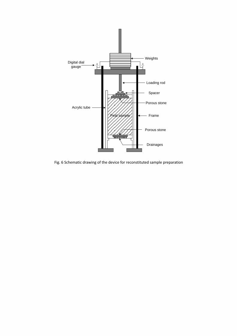
consolidated using a specially designed consolidation apparatus for peat (Fig. 6). Large 241
inclusions including roots and pieces of gravel were removed before placing the peat into 242
the 150mm diameter 350mm height sample preparation acrylic tube. The sample was then 243
subjected to vertical compression under a confining stress of 30 kPa until a settlement rate 244
less than 0.005mm/hour was observed, which usually occurred after approximately 120 245
hours. The compressed sample was pushed out of the tube and trimmed to a length of 246
140mm and a diameter of 70mm for consolidated undrained (CU) triaxial testing. In total, 247
five reconstituted specimens were prepared at initial effective confining stresses ranging 248
from 30 to 200 kPa. 249
A back pressure of 200 kPa was applied to all CU test specimens to achieve full 250
saturation, which was confirmed by checking that the Skempton B values were greater than 251
0.98. The specimens were then isotropically consolidated to the desired value of confining 252
pressure and then a strain controlled undrained triaxial shear test was conducted at a speed 253
of 3% strain per hour. As suggested by Jardine (2013), ageing periods were imposed during 254
the consolidation stage prior to the samples being sheared. During each step, the residual 255
creep rates were reduced to <1% of those that would be developed in the shearing stage. As 256
a result, each sample was consolidated for about 6 days before being sheared to critical 257
state which occurred at a strain of 20% for triaixial compression. The axial load was 258
measured using a load cell and the axial displacement was measured using a linear variable 259
differential transformer (LVDT). 260
Fig. 7 summarizes the results of CU triaxial tests on reconstitutedpeat specimens. The 261

specimens display predominately strain-hardening behaviour up to large deformations (Fig. 262
7(a)), with the exception that slight strain-softening responses were observed for the higher 263
initial effective stresses p’0=100 and 200 kPa. In q-p’ stress space (Fig. 7(b)), the undrained 264
contractive behaviour is primarily seen from the increase in q during strain-hardening 265
accompanied by a decrease in p’ for all specimens. It is also noted that during the later stage 266
of shearing, all specimens exhibit apparent volumetric dilation after passing through the 267
phase transformation state, where the peats behaviour changes from ‘contraction’ to 268
‘dilation’ as is normally observed in sand samples (Ishihara et al 1975). To assist in defining 269
the failure behaviour, the 'tension cut-off' with an inclination q/p'=3 through the origin is 270
also plotted in the q-p’ plane, which signifies a zero effective stress condition. The stress 271
paths are all below this line, indicating that no tensile failure occurs for the WLP samples. 272
Critical state failure is identified for these specimens when the axial strain εa reaches 273
approximately 20% (Fig. 7(a)). ‘Tension cut-off’ failures under triaxial compression are 274
commonly observed in peat, especially for fibrous peat samples (den Hann and Kruse 2007, 275
Mesri and Ajlouni 2007, Zwanenburg et al. 2012). The lack of a 'tension cut-off' failure in the 276
WLP is possibly due to the relatively low fibre content in the WLP (35%) in comparison to 277
other peats. Although some fibres may break in tension, the frictional shear component 278
controls the overall engineering behaviour of this fibrous peat. This type of behaviour is also 279
observed by Yamaguchi et al. (1985) and Cola and Cortellazzo (2005). This suggests that the 280
content and type of organic fibres will determine the failure mechanism and behaviour of 281
fibrous peats during engineering works. 282
The critical state of the peat is approximated by the state of the specimens at 20% axial 283

strain at which the rate of change of effective mean normal stress and deviatoric stress 284
becomes insignificant (Fig. 7). The estimated critical state can be represented by the critical 285
state lines (CSL) in a q-p’ plane and an e-log p’ plane, as shown in Fig. 8 (a) and (b) 286
respectively. In the q-p’ plane (Fig. 8(a)), the soil approaches a unique CSL regardless of its 287
initial states. The critical stress ratio is 1.948, giving a critical state friction angle of 47.3°, 288
which is much higher than those for mineral soils due to the shear resistance caused by 289
organic fibres. Similar observations have been reported by Yamaguchi et al (1985), Long 290
(2005), Mesri and Ajlouni (2007), Hendry et al (2012), O’Kelly and Zhang (2013). In Fig. 8(b), 291
the critical state points can be fitted onto a straight line with a slope of 1.225. The initial 292
states of shearing after isotropic consolidation are also shown in this figure, and they can be 293
fitted onto an isotropic consolidation line (ICL) with a slope of 1.139. 294
The WLP has a distinctive effective stress path in the q-p’ plane. From a very early stage 295
of shearing with small stress ratios q/p’, p’ decreases due to the build-up of pore water 296
pressure (Fig. 7(b)), leading to an inclined effective stress path on which the tangential line 297
of the effective stress path at p’=0 is not vertical. Similar observations are also reported by 298
Yamaguchi et al (1985), Cola and Cortellazzo (2005), Cheng et al (2007), Hendry et al (2012), 299
and Zwanenburg et al. (2012). This suggests plastic deformation could occur for fibrous 300
peats like WLP at very small stress ratios. In the conventional framework of elastoplasticity, 301
the slope of the initial effective stress path in the p’-q plane can be employed to identify the 302
elastic or elastoplastic response of materials. If the soil exhibits purely elastic behaviour 303
under undrained conditions, the 0p
vd , and thus 0e
vd as 0e p
v v vd d d ; then 304
' / 0e
vd dp K , where dεv is the volumetric strain increment with superscripts ‘e’ and ‘p’ 305

signifying elastic and plastic and K is bulk modulus, and therefore no change of p’ occurs, 306
resulting in the tangential line of the effective stress path at p’=0 being perpendicular to the 307
p’ axis. This type of effective stress path is observed in undrained triaxial compression shear 308
test on both sands and normally consolidated clays (Fig. 9), which is confirmed by the small 309
strain behaviour of clays and sands investigated extensively with high-resolution triaxial 310
experiments by Vucetic and Dobry (1988, 1991), Smith et al. (1992), Kuwano and Jardine 311
(2007). Some peats, reported in the literature also display purely elastic behaviour at small 312
stress ratios similar to the behaviour of mineral soils, e.g. those reported by Long (2005), 313
den Haan and Kruse (2007), Mesri and Ajlouni (2007). The reason for these two distinctive 314
behaviours for different peats at very small stress ratios is related to the composition of the 315
peats. The exact elements of the peats which cause this have not been fully understood. 316
However, this again highlights the range of compositions of peat soils which generates the 317
range of observed engineering behaviours. 318
To further verify that plastic deformation occurs in the WLP occurring at the start of 319
shearing, cyclic undrained triaxial compression tests with low amplitudes qcyc=5 kPa and 320
p’0=50 kPa were performed with both Toyoura sand and the WLP samples. The loading 321
programme is shown in Fig. 10(a). Fig. 10(b) compares the stress paths of peat and sand in 322
the first loading cycle. As expected, the stress path for the sand is almost vertical in the first 323
cycle without generating any pore pressure, in comparison the WLP is not vertical, with a net 324
pore pressure of 5 kPa generated in the first cycle. Fig. 10(c) presents the accumulative axial 325
strains in the first cycle. Nearly 0.06% axial strain takes place in the first cycle for the WLP, 326
while no discernable strain is produced for the sand. Similar observations are confirmed by 327

dynamic triaxial tests on peats at small strain carried out by Boulanger et al. (1998), Kramer 328
(2000), Wehling et al. (2003), in which purely elastic, linear and non-hysteretic responses 329
were not observed, even at extremely small stress/strain levels, such as would be seen in 330
other siliciclastic soils. This behaviour of the peat forms one of the key elements of the 331
constitutive model presented in the following section. 332
333
A simple triaxial compression model 334
During the last several decades, critical-state soil mechanics (Schofield and Wroth 1968) has 335
been extensively used to model the behaviours of both sand and clay (Li and Dafalias 2000; 336
Ling and Yang 2006; Kaliakin and Dafalias 1990; Schofield and Wroth 1968). For example, Li 337
and Dafalias (2000) proposed a state-dependent dilatancy model for sand, which is capable 338
of describing sand behaviour at different initial densities and under different initial confining 339
pressures with a single set of model constants. Given the advantage of Li and Dafalias' model, 340
it was adopted to simulate the undrained triaxial compression behaviour of WLP. 341
The critical state line in the e-p' plane can be expressed as (Li and Wang 1998) 342
'( / )c c ae e p p Eq. (2) 343
where ec is the critical state void ratio corresponding to p’, and eГ, λc and ξ are three material 344
constants for critical state line. Using this equation, the state parameter ψ proposed by Been 345
and Jefferies (1985) can be obtained as 346
ce e Eq. (3) 347
where e is the void ratio at the current state. The sign of ψ can be used to determine the 348
state of the soil considering the influence of both density and pressure (Been and Jefferies 349

1985; Li and Dafalias 2000). 350
As shown in Fig. 7, the critical state of the WLP is approximated by the state of the 351
specimens at approximately 20% axial strain at which the rate of change of both deviatoric 352
and mean normal effective stresses becomes insignificant. Under undrained conditions, it is 353
assumed that plastic deformation can only occur when the stress ratio η=q/p' exceeds its 354
historic maxima for virgin loading, and no plastic deformation will be produced along a 355
constant η stress path. This assumption is approximately true for sand, as no significant 356
volume change is induced for a constant stress ratio η under normal confining stress levels, 357
before particle breakage occurs. However, for clay and peat, considerable volumetric 358
deformation is observed due to consolidation, and thus the plastic deformation which 359
occurs along a constant η stress path cannot be neglected. In this study, given that only 360
undrained triaxial tests were performed, no yielding occurs due to increases in p'. Thus this 361
assumption is still valid. The yield criterion can be written as (Li and Dafalias 2000) 362
' 0f q p Eq. (4) 363
The condition of consistency of the yield function of Eq. (4) can be expressed as: 364
'
'0p
f fdf dp dq L K
p q
Eq. (5) 365
in which Kp is the plastic modulus and L is the loading index defined as 366
' ''
'
1( )
p p p
f f dq dp p dL dp dq
K p q K K
Eq. (6) 367
An associated flow rule is applied in deviatoric space, such that 368
' /p
q p
fd L p d K
q
Eq. (7) 369
where is the Macauley bracket such that L L for 0L and 0L when 0L . 370

By applying a dilatancy relation, the plastic volumetric strain increment can be written as 371
' /p p
v q p
fd Dd D L Dp d K
q
Eq. (8) 372
Where, the following dilatancy function is proposed, 373
0( / )mD d e M Eq. (9) 374
In which d0 and m are two material constants for the dilatanty equation and M is the critical 375
stress ratio. Eq. (9) is slightly different from the one employed by Li and Dafalias (2000) for 376
fine tuning the performance of their model. It can be seen that at the critical state, ψ=0 and 377
η=M, the dilatancy D is zero according to Eq. (9), which satisfies the requirement for the 378
critical state. More importantly, this equation can also describe both positive and negative 379
dilatancy, depending on the state of the soils which is characterized by the state parameter 380
ψ. 381
The elastic strain increments can be obtained through linear elasticity as 382
' /e
vd dp K and / 3e
qd dq G Eq. (10) 383
in which dεve and dεv
p are elastic and plastic strain increments respectively; G and K denote 384
the elastic shear and bulk moduli respectively. As the elastic properties of soils are normally 385
pressure sensitive, G can be expressed by an empirical formula as follows, 386
' 0.5
0 ( )( )aG G F e p p Eq. (11) 387
in which G0 is a dimensionless material constant and can be determined by resonant column 388
tests; pa is the atmospheric pressure for normalization; F(e) is a function of the current void 389
ratio e with a typical form of (Hardin and Richart 1963; Richart et al 1970; Iwasaki and 390
Tatsuoka 1977) 391

2(2.97 )( )
1
eF e
e
Eq. (12) 392
The bulk modulus K can be expressed as 393
2(1 )
3(1 2 )K G
Eq. (13) 394
where ν is Poisson's ratio of soils and for simplicity, can be treated as a material constant 395
independent of the pressure. 396
Noting the additive decomposition of the strains e p
v v vd d d and e p
q q qd d d , and 397
by combing Eqs. (7) - (9), we can obtain the incremental stress-strain relation in triaxial 398
space, 399
'
q
v
ddq
ddp
Eq. (14) 400
where Λ is the elastoplastic stiffness matrix and can be explicitly expressed as 401
2
2
3 0 9 3( )
0 3 3 Dp
G G KGh L
K K G K D KGD K
Eq. (15) 402
where ( )h L is the Heaviside step function, with ( 0) 1h L and ( 0) 0h L . 403
The plastic modulus is defined to capture the hardening and softening of soil responses 404
under shear loading. Given the lack of information from observed plastic hardening 405
behaviour associated with microstructural evolution, the plastic modulus Kp can also be 406
defined as a function of the stress ratio η and state parameter ψ, 407
( ) ( )n n n
pK Gh M e Ghe Me Eq. (16) 408
where h and n are two positive model constants; the elastic modulus G serves as a reference, 409
rendering h dimensionless. Eq. (16) is a modified version of that employed for modelling 410
sands by Li and Dafalias (2000), which is intended to model the exact response at stress ratio 411

η=0. It is seen that Eq. (16) inherits the merits of its original form for sand. For example, at 412
the critical state, ψ=0 and η=M, which result in Kp=0, such that / 0p
qd d , which coincides 413
with the condition of perfect plastic flow at the critical state. In addition: 1) Kp can be 414
positive or negative, depending on the value of ψ, such that it can describe a hardening or 415
softening response during shearing; 2) Kp used by Li and Dafalias (2000) will become infinite 416
when η=0, indicating that no plastic deviatoric strain occurs, nor is there any plastic 417
volumetric strain. This holds true for most normally consolidated soils, which have a purely 418
elastic response with a non-zero, small dη at η=0, resulting in 0p
qd and such that 0p
vd . 419
0p
qd yields an isotropic deformation, while 0p
vd suggests that the tangent of the 420
effective stress path in the q-p' will be vertical, and no change in the effective p' is allowed to 421
take place under undrained conditions. However, for WLP, the effective stress path bends 422
towards the reduction in effective stress p' right from the starting point at η=0 (Fig. 7b), and 423
there is no purely elastic zone as discussed before. 424
The model variable h in Eq. (16) is found to be void ratio (e)-dependent, and a simple 425
linear relation is proposed by Li and Dafalias (2000) as 426
1 2h h h e Eq. (17) 427
where h1 and h2 are two material constants. Eq. (18) has integrated the influence of the soil 428
density over a wide range of variation. As noted by Li (2002), an e-dependent function is 429
used rather than a ψ-dependent function, because a change either in e or p' will alter ψ, 430
while the influence of p' has been accounted for by the elastic shear modulus G in Eq. (11). 431
432
Model calibration and responses 433

In total, 11 material constants should be calibrated and used in this model. These constants 434
can be grouped into four categories (Table 2) according to their functions. The critical stress 435
ratio M is obtained by fitting the results of triaxial compression tests in the q-p’ plane in Fig. 436
7(a). Parameters eГ, λc, and ξ are determined by fitting the test data with linearization of the 437
critical state line in the e-p’ plane with Eq. (2), which is shown in Fig. 11 (Li and Wang 1998). 438
The elastic, dilatancy and hardening parameters can be calibrated and adjusted finely to fit 439
the test data, using the calibration procedure described in Li and Dafalias (2000). All 440
resulting constants are presented in Table 2. 441
In general, the model simulations compare well with the experimental results (Fig. 12). 442
the model is able to simulate the response of WLP at low stress ratio levels, where the 443
effective stress paths bend towards the reduction of the effective stresses in the q-p’ plane 444
(Fig. 12(a)). The model can also capture the stress-strain responses from small strain levels 445
up to the critical state (Fig. 12(b)). Slight discrepancies are observed at very low strain levels. 446
These are probably related to the uncertainties associated with the accurate measurement 447
of the true small strain behaviour of undisturbed peat, and the uncertain behaviour of 448
deformable organic particles at these small strains. 449
450
Conclusions 451
The following five main conclusions flow from the work described above: 452
1. The West Lake Peat (WLP) investigated in this study is similar in many ways to typical 453
peats: it has a relatively high water content and low bulk density, it is highly 454
compressible and its secondary compression is significant. However, although the fibre 455

content of WLP is significant it is not dominant. 456
2. The undrained shear behaviour of WLP can be described using critical state theory. No 457
‘tension cut-off’ failure was observed prior to occurrence of critical state failure, which is 458
primarily due to its relatively low fibre content. In addition, the WLP has a higher critical 459
state friction angle of approximately 47.3o, which is much higher than those of mineral 460
soils and is normally caused by the reinforcing effect of fibres in peats. 461
3. The most prominent observation of the WLP is that plastic deformation occurs at very 462
small stress levels. The feature is very similar to the behaviour of many peats worldwide, 463
while most mineral soils behave elastically under similar low stress ratios. 464
4. A constitutive model is presented that has simulative capability in predicting the 465
undrained shear behaviour. The model response compares well with the experimental 466
results from the beginning of shearing through to critical state failure. 467
5. Given that the WLP has intermediate behaviour in comparison to other peats, this model 468
has sufficient flexibility to describe the behaviour of a wide range of peats. 469
470
The results of this study provide a fundamental basis for understanding the engineering 471
behaviour of the WLP in Jiangyangfan Eco-park. It has been used to inform the remedial 472
works for existing structures and foundation works for future buildings/structures in the 473
park. At the broader scale this work provides another case study of the behaviour of a peat 474
and highlights the wide variety of potential behaviours of this diverse and variable 475
geotechnical material. 476
477
Acknowledgments 478
The research described was funded by the Natural Science Foundation of China (Grant Nos. 479
51322809, 51578499), Qianjiang Manage Office of Hangzhou Administration Bureau of 480
Gardens, the National Key Basic Research Program of China (No. 2015CB057801). Their 481
support is gratefully acknowledged. Gratitude is also extended to Dr XS Li, for insightful 482
discussions and constructive comments on the constitutive modelling of peat. 483
484
References 485
Been, K., and Jefferies, M.G. (1985). A state parameter for sands. Géotechnique, 35(2), 486
99-112. 487
Berry, P.L., and Poskitt, T. J. (1972). The consolidation of peat. Géotechnique, 22(1), 27-52. 488
British Standards Institution, 1999. Code of practice for site investigation, BS 5930:1999. Her 489
Majesty's Stationary Office, London. 490
British Standards Institution, 2002. Geotechnical investigation and testing — Identification 491
and classification of soil, BS EN ISO 14688-1: 2002. Her Majesty's Stationary Office, 492
London. 493
Boulanger, R.W., Arulnathan, R., Harder, L.F.Jr., Torres, R.A., and Driller, M.W. (1998). Dynamic 494
properties of Sherman Island peat. Journal of Geotechnical and Geoenvironmental 495
Engineering, 124(1), 12-20. 496
Boumezerane, D. (2014). Modeling unloading/reloading in peat using a kinematic bubble 497
model. Numerical Methods in Geotechnical Engineering, Hick, Bringreve & Rohe (Eds), 498
Taylor & Francis Group, London, 1, 9-14. 499

Cheng, X.H., Ngan-Tillard, D.J.M., and den Haan, E.J. (2007). The causes of the high friction 500
angle of Dutch organic soils. Engineering Geology, 93(1), 31-44. 501
Cola, S., and Cortellazzo, G. (2005). The shear strength behaviour of two peaty soils. 502
Geotechnical and Geological Engineering, 23(6), 679-695. 503
den Haan, E.J., and Kruse, G.A.M. (2007). Characterisation and engineering properties of 504
Dutch peats. In Proceedings of the Second International Workshop of Characterisation 505
and Engineering Properties of Natural Soils, Singapore, 29, 2101-2133. 506
den Haan, E.J., and Grognet, M. (2014). A large direct simple shear device for the testing of 507
peat at low stresses, Géotechnique Letters, 4, 283-288. 508
den Haan, E.J., and Feddema, A. (2013). Deformation and strength of embankments on soft 509
Dutch soil, Proceedings of the ICE-Geotechnical Engineering, 166(GE3), 239-252. 510
Edil, T.B., Fox, P.J., and Lan, L.T. (1991). Observational procedure for settlement of peat. Proc. 511
Geo-Coast, 91, 165-170. 512
Hangzhou local Chronicles compilation committee (2003). Chronicles of Hangzhou. 513
http://www.hangzhou.gov.cn/main/zjhz/hzsz/index.jsp (in Chinese). 514
Hardin, B.O., and Richart, F.E. (1963). Elastic wave velocities in granular soils. Journal of Soil 515
Mechanics and Foundations Division, ASCE, 89(SM1), 39-56. 516
Hendry, M.T., Sharma, J.S., Martin, C.D., & Barbour, S.L. (2012). Effect of fibre content and 517
structure on anisotropic elastic stiffness and shear strength of peat. Canadian 518
Geotechnical Journal, 49(4), 403-415. 519
Hobbs, N.B. (1986) Mire morphology and the properties and behaviour of some British and 520
foreign peats. Quart. J. of Eng. Geol., 19: 7-80. 521
Ishihara K., Tatsuoka F., and Yasuda S. (1975). Undrained deformation and liquefaction of 522
sand under cyclic stresses. Soils Foundations, 15(1), 29–44. 523
Iwasaki, T., and Tatsuoka, F. (1977). Effects of grain size and grading on dynamic shear moduli 524
of sand. Soils and Foundations, 17(3), 19-35. 525
Jardine, R.J. (2013). Advanced laboratory testing in research and practice. 2nd Bishop 526
Lecture, 18th Conf. on Soil Mechanics and Geotechnical Engineering, Publisher: Presses 527
des Ponts, 25-55. 528
Long, M. (2005). Review of peat strength, peat characterisation and constitutive modelling 529
of peat with reference to landslides. Studia Geotechnica et Mechanica, 27(3-4), 67-90. 530
Kaliakin, V., and Dafalias, Y.F. (1990). Theoretical aspects of the elastoplastic-viscoplastic 531
bounding surface model for cohesive soils. Soils and Foundations, 30(3), 11–24. 532
Kazemian, S., B.K. Huat, B.B.K., Prasad, A. and Barghchi, M. (2011). A state of art review of 533
peat: Geotechnical engineering perspective. International Journal of the Physical 534
Sciences, 6(8), 1974-1981. 535
Kramer, S.L. (2000). Dynamic response of Mercer Slough peat. Journal of Geotechnical and 536
Geoenvironmental Engineering, 126(6), 504-510. 537
Kuwano, R., and Jardine, R.J. (2007). A triaxial investigation of kinematic yielding in sand. 538
Géotechnique, 57(7), 563-579. 539
Kvæ rner, J., and Snilsberg, P. (2008). The Romeriksporten railway tunnel-drainage effects on 540
peatlands in the lake Northern Puttjern area. Engineering Geology, 101(3), 75-88. 541
Long, M., and Jennings, P. (2006). Analysis of the peat slide at Pollatomish, County Mayo, 542
Ireland. Landslides, 3, 51–61. 543

Li, X.S. (2002). A sand model with state-dependent dilatancy. Géotechnique, 52(3), 173-186. 544
Li, X.S., and Dafalias, Y.F. (2000). A sand model with state-dependent dilatancy. 545
Géotechnique, 50(4), 449-460. 546
Li, X.S., and Wang, Y. (1998). Linear representation of steady-state line for sand. Journal of 547
Geotechnical and Geoenvironmental Engineering, 124(12), 1215-1217. 548
Ling, H. I., and Yang, S. (2006). Unified sand model based on the critical state and generalized 549
plasticity. Journal of Engineering Mechanics, 132(12), 1380–1391. 550
Mesri, G., and Ajlouni, M. (2007). Engineering properties of fibrous peats. Journal of 551
Geotechnical and Geoenvironmental Engineering ASCE, 133(7), 850-866. 552
Mesri, G., and Choi, Y.K. (1985). Settlement analysis of embankments on soft clays. Journal 553
of Geotechnical Engineering, 111(4), 441-464. 554
Mesri, G., Stark, T.D., Ajlouni, M.A., and Chen, C.S. (1997). Secondary compression of peat 555
with or without surcharging. Journal of Geotechnical and Geoenvironmental 556
Engineering, 123(5), 411-421. 557
Nichol, D., and Farmer, I.W. (1998). Settlement over peat on the A5 at Pant Dedwydd near 558
Cerrigydrudion, North Wales. Engineering Geology, 50(3), 299-307. 559
O’Kelly, B.C., and Zhang, L. (2013). Consolidated-drained triaxial compression testing of peat. 560
ASTM Geotechnical Testing Journal, 36(3), 310-321. 561
Pichan, S.P. and O'Kelly, B.C. (2012). Effect of decomposition on the compressibility of fibrous 562
peat, ASCE GeoCongress 2012: State of the Art and Practice in Geotechnical 563
Engineering, Oakland, California, USA, 25th–29th March, 2012, edited by R.D. Hryciw, A. 564
Athanasopoulos-Zekkos and N. Yesiller, (GSP 225), 4329 – 4338. 565
Pichan, S.P., and O'Kelly, B.C. (2012). Stimulated decomposition in peat for engineering 566
applications. Proceedings of the ICE-Ground Improvement, 166(3), 168-176. 567
Radforth, N.W. (1969). Classification of muskeg. In: MacFarlane, I. C. (ed.) Muskeg 568
engineering handbook. Canadian Building Series. University of Toronto Press. 569
Richard, F.E., Hall, J.R., Woods, R.D. (1970). Vibrations of soils and Foundations. Prentice-Hall: 570
Englewood Cliffs, NJ, 1970. 571
Schofield, A.N., and Wroth, C.P. (1968). Critical state soil mechanics, McGraw Hill, London 572
Shao, Y.F., He, C., Lou, Q.Q. (2007). Stabilization of dredged silt from West Lake. Journal of 573
Jiangsu University (Natural Science Edition), 28(5), 442-445. (in Chinese). 574
Shu, S. (1090). The request of dredging West Lake in Hangzhou. 575
http://blog.sina.com.cn/s/blog_500bc46501012fe3.html, in Chinese. 576
Skempton, A. W., & Petley, D. J. (1970). Ignition loss and other properties of peats and clays 577
from Avonmouth, King's Lynn and Cranberry Moss. Géotechnique, 20(4), 343-356. 578
Smith, P.R., Jardine, R.J., and Hight, D.W. (1992). The yielding of Bothkennar clay. 579
Géotechnique, 42(2), 257-274. 580
Standard for Soil Test Method (SSTE 1999). National Standard of the People’s Republic of 581
China, GB/T50123-1999. China Planning Press, October 1999. 582
Wehling, T.M., Boulanger, R.W., Arulnathan, R., Harder, L.F. Jr, and Driller, M.W. (2003). 583
Nonlinear dynamic properties of a fibrous organic soil. Journal of Geotechnical and 584
Geoenvironmental Engineering, 129(10), 929-939. 585
Wilkinson, S. (2011). The Microstructure of UK Mudrocks, PhD thesis, Department of Civil 586
and Environmental Engineering, Imperial College London. 587

von Post, L. (1922) Sveriges Geologiska Undersoknings torvinventering och nogra av dess 588
hittils vunna resultat (SGU peat inventory and some preliminary results). Svenska 589
Mosskulturforeningens Tidskrift, Jonkoping, Sweden, 36, 1-37. 590
Vucetic, M., and Dobry, R. (1988). Degradation of marine clays under cyclic loading. Journal 591
of Geotechnical Engineering, 114(2), 133-149. 592
Vucetic, M., and Dobry, R. (1991). Effect of soil plasticity on cyclic response. Journal of 593
Geotechnical Engineering, 117(1), 89-107. 594
Yamaguchi, H., Ohira, Y., Kogure, K., and Mori, S. (1985). Undrained shear characteristics of 595
normally consolidated peat under triaxial compression and extension conditions. Soils 596
and foundations, 25(3), 1-18. 597
Zhang, L., and O’Kelly, B.C. (2014). The principle of effective stress and triaxial compression 598
testing of peat. Proceedings of the ICE-Geotechnical Engineering, 167(GE1), 40-50. 599
Zwanenburg, C., den Haan, E.J., Kruse, G.A.M., and Koelewijn, A.R. (2012). Failure of a trial 600
embankment on peat in Booneschans, the Netherlands. Géotechnique, 62(6), 479-490. 601

Beijing
Hangzhou
Shanghai
Taipei
Hong Kong
The West Lake
Jiangyangfan Eco-park
Qiantang River
Fuxing Bridge
0 2 km1
N
Fig. 1 Maps showing sites of West Lake in Hangzhou and Jiangyangfan Eco-park

Fig. 2 Contour diagram of thickness of the peat deposited at Jiangyangfan Eco-park

Fig. 3 Chronological aerial views of Jiangyangfan Eco-park site

Fig. 4 Scanning electron microscope images of peat samples (a) organic fibres; (b), (c) and (d)
stem structures; (e) leaves; (f) pyritic framboids
(c) (d)
(a) (b)
(e) (f)

30
20
10
00.1 1 10 100 1000
Elapsed time (min)
Axia
l str
ain
(%
)
12.5kPa
25.0kPa
50.0kPa(a)
1 10 100 1000
2
4
6
8
10
remoulded void ratio
e0=3.86
Vertical stress v (kPa)
Vo
id r
atio
e
intact void ratio
e0=6.78-8.48
(b)
1
cc=1.23
Fig. 5 One-dimensional compression of the WLP
(a) loading increment against elapsed time; (b) e-log(σv) curve;
Weights
Spacer
FramePeat sample
Porous stone
Digital dial
gauge
Porous stone
Loading rod
Drainages
Acrylic tube
Fig. 6 Schematic drawing of the device for reconstituted sample preparation

0 5 10 15 20 250
50
100
150
200
250
300
p'
0=30 kPa
p'
0=50 kPa
p'
0=100 kPa
p'
0=150 kPa
Devia
toric s
tress q
(kP
a)
Axial strain a (%)
p'
0=200 kPa
(a)
0 50 100 150 200 2500
50
100
150
200
250
300
Devia
toric s
tress q
(kP
a)
Mean normal effective stress p' (kPa)
p'
0=30 kPa
p'
0=50 kPa
p'
0=100 kPa
p'
0=150 kPa
p'
0=200 kPa
(b)
q/p'=3
tension cut-off
Fig. 7 Triaxial compression tests for peat (a) effective stress paths; (b) stress-strain curves

0 50 100 150 200 2500
50
100
150
200
250
300
De
via
toric s
tre
ss q
(kP
a)
Mean normal effective stress p' (kPa)
M=1.948
1
(a)
1001.8
2.1
2.4
2.7
3.0
5020 300
Mean normal effective stress p' (kPa)
Void
ratio e
200
ICL
CSL
1
1.1391
1.225
(b)
Fig. 8 Critical state line (a) q-p' plane; (b) e-logp' plane

p'
qsand
clay
CSL
Fig. 9 Typical effective stress paths for sand and normally consolidated clay

0 2 4 6 80.0
1.5
3.0
4.5
6.0
De
via
toric s
tre
ss (
kP
a)
No of cycles
(a)
0 20 40 600.0
1.5
3.0
4.5
6.0
Devia
toric s
tress q
(kP
a)
Mean normal effective stress p' (kPa)
sand
peat
(b)
0.00 0.02 0.04 0.06 0.08 0.100.0
1.5
3.0
4.5
6.0
Axial strain a (%)
De
via
toric s
tre
ss q
(kP
a)
Sand
Peat
(c)
Fig. 10 Peat response under low-amplitude cyclic loading (a) cyclic deviatoric (qcyc=5kPa) loading;
(b) 1st cycle response in q-p' plane; (c) 1st cycle response in q-εa plane

25 50 75 100 12515
Experimental
Mean effective stress p’ (kPa)
Vo
id R
atio
e
1.8
2.0
2.2
2.4
2.6
2.8
3.0
150
e=7.57-5.59(p’/pa)0.1
Fig. 11 Linearized critical state line for peat in the constitutive modelling

0 50 100 150 200 2500
50
100
150
200
250
300
Mean effective pressure p' (kPa)
De
via
toric s
tre
ss q
(kP
a)
(a) Model response
Test results
0 5 10 15 20 250
50
100
150
200
250
300
Axial strain a (%)
Devia
toric s
tress q
(kP
a)
p'
0=30kPa
p'
0=50kPa
p'
0=100kPa
p'
0=150kPa
p'
0=200kPa(b)
Fig. 12 Comparison between experimental results and model responses for peat
(a) effective stress path; (b) stress-strain curve
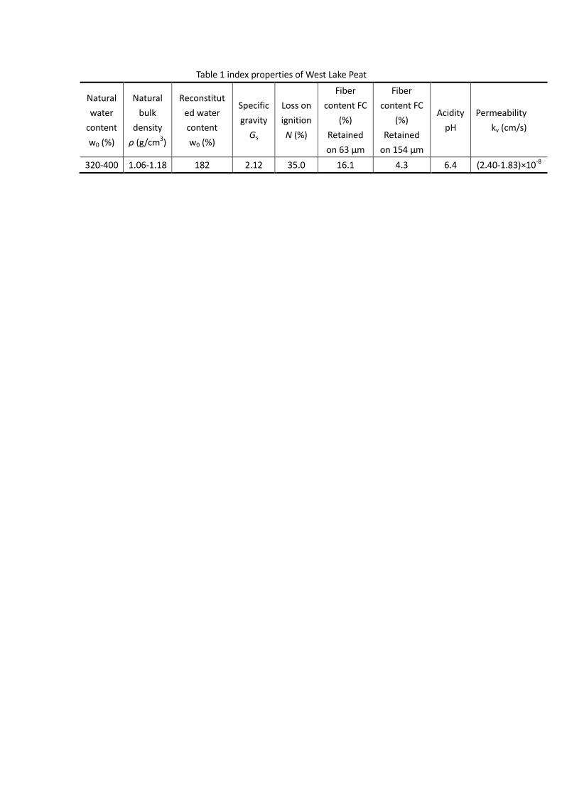
Table 1 index properties of West Lake Peat
Natural
water
content
w0 (%)
Natural
bulk
density
ρ (g/cm3)
Reconstitut
ed water
content
w0 (%)
Specific
gravity
Gs
Loss on
ignition
N (%)
Fiber
content FC
(%)
Retained
on 63 μm
Fiber
content FC
(%)
Retained
on 154 μm
Acidity
pH
Permeability
kv (cm/s)
320-400 1.06-1.18 182 2.12 35.0 16.1 4.3 6.4 (2.40-1.83)×10-8

Table 2 Model parameters for West Lake Peat
Elastic
Parameters
Critical state
parameters
Dilatancy
parameters
Hardening
parameters
G0=109 M=1.948 d0=0.08 h1=0.587
ν=0.209 eГ=7.57 m=0.105 h2=0.139
λc =5.59 n=0.105
ξ=0.1