
Terrain-flattened gamma nought Radarsat-2 backscatter · est teste´e en corre´lant chaque image...
7
Research Note / Note de recherche Terrain-flattened gamma nought Radarsat-2 backscatter David Small, Lukas Zuberbu ¨ hler, Adrian Schubert, and Erich Meier Abstract. Radarsat-2 offers a variety of new modes and capabilities. We present results from rigorous application of geometric and radiometric calibration to backscatter values, enabling comparisons between different modes. First, the system’s a priori geometric accuracy was tested (tiepoint free) by comparing the measured positions of corner reflectors in ultrafine images with predicted locations calculated based on the satellite state vectors and radar timing annotations. Second, the geometric accuracy of the dual-pol ScanSAR SCNB mode was tested by correlating each backscatter image to a radar image simulation calculated using the same product annotations. Third, the radar image simulation was used to normalize the backscatter values in both polarisations, generating terrain-flattened gamma nought values that were then terrain geocoded. Fourth, the available ascending and descending SCNB image pair was overlaidwith and without such radiometric terrain correction applied. The advantages gained by using terrain-flattened gamma nought are discussed. Re ´sume ´. RADARSAT-2 offre une varie ´te ´ de nouveaux modes et fonctionnalite ´s. Nous pre ´sentons les re ´sultats obtenus par l’application rigoureuse de la calibration ge ´ome ´trique et radiome ´trique sur les valeurs de re ´trodiffusion, permettant de comparer les diffe ´rents modes. Premie `rement, la pre ´cision ge ´ome ´trique a priori du syste `me est teste ´e (sans points de soutien) en comparant les positions de re ´flecteurs trie `dres mesure ´es sur les images ultra-fines avec les positions pre ´vues, ces dernie `res e ´tant calcule ´es a ` partir des annotations contenant les vecteurs d’e ´tat du satellite ainsi que les parame `tres temporaux du radar. Deuxie `mement, la pre ´cision ge ´ome ´trique du mode ScanSAR en polarisation double (appele ´ SNCB) est teste ´e en corre ´lant chaque image de re ´trodiffusion avec une image radar simule ´e, ge ´ne ´re ´e en utilisant les vecteurs d’e ´tat et les parame `tres temporaux extraits des annotations en combinaison avec un MNT. Troisie `mement, cette image radar simule ´e est utilise ´e pour normaliser les valeurs de re ´trodiffusion des deux polarisations, ge ´ne ´rant des valeurs de gamma ze ´ro normalise ´es selon le relief, qui sont ensuite ge ´ocode ´es. Quatrie `mement, la paire d’images SCNB (1 ascendante, 1 descendante) est superpose ´e une fois sans et une fois avec l’application de cette correction radiome ´trique du terrain. Les avantages de l’utilisation de gamma ze ´ro normalise ´ selon le relief sont discute ´s. [Traduit par la Re ´daction] Introduction Both the geometric and radiometric quality of any synthetic aperature radar (SAR) sensor determines whether or not its data can be applied to the wide range of SAR applications. Maximizing the accuracy of tiepoint-free geolocation ensures that SAR products can be easily combined with other geospatial data. This enables a combination of SAR imagery and its derivative products with digital elevation models (DEMs) (Meier et al., 1993). The same DEMs may also be used to terrain flatten the retrieved backscatter values (Small, 2011). The beta nought (b 0 ) backscatter convention (Raney et al., 1994) is best used when storing level 1 radar backscatter values in slant range geometry, as it offers the least encumbered methodology for keeping the actual radar measurements. Translation of the recorded backscatter values into the sigma nought (s 0 ) or gamma nought (g 0 ) conventions requires the use of an Earth model, either a simple ellipsoidal Earth (Rosich and Meadows, 2004; ESA, 2007), or a more detailed DEM. In the former case, the subscript E can be used to indicate the use of an Ellipsoidal Earth model (r 0 E and c 0 E ), while in the latter case, the subscript T can be used (r 0 T and c 0 T ) to indicate the use of a terrain model (Small et al., 2009a). The radiometric look-up tables (LUTs) included with Radarsat-2 (R2) products (MDA, 2008) were generated using an ellipsoidal Earth model. When an image simulation is performed conforming Received 31 March 2011. Accepted 14 September 2011. Published on the Web at http://pubs.casi.ca/journal/cjrs on 8 March 2012. D. Small 1 , L. Zuberbu ¨hler, A. Schubert, and E. Meier. Remote Sensing Laboratories, Dept. of Geography, University of Zurich, Winterthurerstrasse 190, CH-8057 Zurich, Switzerland. 1 Corresponding author (e-mail: [email protected]). Can. J. Remote Sensing, Vol. 37, No. 5, pp. 493499, 2011 # 2012 CASI 493 Canadian Journal of Remote Sensing Downloaded from pubs.casi.ca by HAUPTBIBLIOTHEK UNIVERSITAET ZUERICH on 03/21/12 For personal use only.
Transcript of Terrain-flattened gamma nought Radarsat-2 backscatter · est teste´e en corre´lant chaque image...

Research Note / Note de recherche
Terrain-flattened gamma nought Radarsat-2backscatter
David Small, Lukas Zuberbuhler, Adrian Schubert, and Erich Meier
Abstract. Radarsat-2 offers a variety of new modes and capabilities. We present results from rigorous application of
geometric and radiometric calibration to backscatter values, enabling comparisons between different modes. First, the
system’s a priori geometric accuracy was tested (tiepoint free) by comparing the measured positions of corner reflectors in
ultrafine images with predicted locations calculated based on the satellite state vectors and radar timing annotations.
Second, the geometric accuracy of the dual-pol ScanSAR SCNB mode was tested by correlating each backscatter image
to a radar image simulation calculated using the same product annotations. Third, the radar image simulation was used to
normalize the backscatter values in both polarisations, generating terrain-flattened gamma nought values that were then
terrain geocoded. Fourth, the available ascending and descending SCNB image pair was overlaid with and without such
radiometric terrain correction applied. The advantages gained by using terrain-flattened gamma nought are discussed.
Resume. RADARSAT-2 offre une variete de nouveaux modes et fonctionnalites. Nous presentons les resultats obtenus par
l’application rigoureuse de la calibration geometrique et radiometrique sur les valeurs de retrodiffusion, permettant de
comparer les differents modes. Premierement, la precision geometrique a priori du systeme est testee (sans points de
soutien) en comparant les positions de reflecteurs triedres mesurees sur les images ultra-fines avec les positions prevues,
ces dernieres etant calculees a partir des annotations contenant les vecteurs d’etat du satellite ainsi que les parametres
temporaux du radar. Deuxiemement, la precision geometrique du mode ScanSAR en polarisation double (appele SNCB)
est testee en correlant chaque image de retrodiffusion avec une image radar simulee, generee en utilisant les vecteurs d’etat
et les parametres temporaux extraits des annotations en combinaison avec un MNT. Troisiemement, cette image radar
simulee est utilisee pour normaliser les valeurs de retrodiffusion des deux polarisations, generant des valeurs de gamma
zero normalisees selon le relief, qui sont ensuite geocodees. Quatriemement, la paire d’images SCNB (1 � ascendante,
1 � descendante) est superposee une fois sans et une fois avec l’application de cette correction radiometrique du terrain.
Les avantages de l’utilisation de gamma zero normalise selon le relief sont discutes.
[Traduit par la Redaction]
Introduction
Both the geometric and radiometric quality of any
synthetic aperature radar (SAR) sensor determines whether
or not its data can be applied to the wide range of SAR
applications. Maximizing the accuracy of tiepoint-free
geolocation ensures that SAR products can be easily
combined with other geospatial data. This enables a
combination of SAR imagery and its derivative products
with digital elevation models (DEMs) (Meier et al., 1993).
The same DEMs may also be used to terrain flatten the
retrieved backscatter values (Small, 2011).
The beta nought (b0) backscatter convention (Raney
et al., 1994) is best used when storing level 1 radar
backscatter values in slant range geometry, as it offers the
least encumbered methodology for keeping the actual radar
measurements. Translation of the recorded backscatter
values into the sigma nought (s0) or gamma nought (g0)
conventions requires the use of an Earth model, either a
simple ellipsoidal Earth (Rosich and Meadows, 2004; ESA,
2007), or a more detailed DEM. In the former case, the
subscript E can be used to indicate the use of an Ellipsoidal
Earth model (r0E and c0
E), while in the latter case, the
subscript T can be used (r0T and c0
T) to indicate the use of a
terrain model (Small et al., 2009a). The radiometric look-up
tables (LUTs) included with Radarsat-2 (R2) products
(MDA, 2008) were generated using an ellipsoidal Earth
model. When an image simulation is performed conforming
Received 31 March 2011. Accepted 14 September 2011. Published on the Web at http://pubs.casi.ca/journal/cjrs on 8 March 2012.
D. Small1, L. Zuberbuhler, A. Schubert, and E. Meier. Remote Sensing Laboratories, Dept. of Geography, University of Zurich,Winterthurerstrasse 190, CH-8057 Zurich, Switzerland.
1Corresponding author (e-mail: [email protected]).
Can. J. Remote Sensing, Vol. 37, No. 5, pp. 493�499, 2011
# 2012 CASI 493
Can
adia
n Jo
urna
l of
Rem
ote
Sens
ing
Dow
nloa
ded
from
pub
s.ca
si.c
a by
HA
UPT
BIB
LIO
TH
EK
UN
IVE
RSI
TA
ET
ZU
ER
ICH
on
03/2
1/12
For
pers
onal
use
onl
y.

strictly to the gamma nought convention while integrating
all available height information, including checks for local
occlusions (radar shadow), then the actual area visible to the
radar (in the plane perpendicular to the slant range plane)
can be retrieved. A method to estimate that area
and then also the backscatter parameter known as terrain-
flattened gamma nought (c0T) was described in Small (2011).
Tiepoint-free geolocation accuracy
A pair of ascending and descending ultrafine (UF) R2
images was acquired from Torny-le-Grand, Switzerland on
2 March and 10 May 2010. Two pairs of corner reflectors
(CRs) were deployed within each scene; their phase centres
were surveyed using a differential global positioning system
(DGPS) (Small et al., 2004; Schubert et al., 2010). The
surveyed coordinates were used in combination with the
satellite’s state vectors and radar timing annotations pro-
vided in the SAR product header to predict the location of
each coordinate within each image raster. That prediction
was then compared with the actual measured image location
calculated to subsample accuracy by virtue of oversampling.
Close-ups of the corner reflectors in each image are shown
in Figure 1.
The predictions are shown with yellow crosses at full
single-look complex (SLC) resolution. The actual measured
corner reflector locations are visible in the images them-
selves. As the two CRs were quite close to each other, there
was some overlap in the regions surrounding each prediction
cross. Although the range prediction’s accuracy was less
than 1 UF SLC sample, an azimuth bias of 10�12 UF SLC
samples was detected. When the same geolocation metho-
dology is applied to products from the instruments ASAR
(ESA ENVISAT), PALSAR (JAXA ALOS), or TSX (DLR/
InfoTerra TerraSAR-X), no such azimuth bias is detectable.
In the case of ASAR products processed with the standard
ESA ASAR processing facility (PF-ASAR), a deterministic
‘‘azimuth bistatic shift’’ must be compensated (Small et al.,
2004) but that induces no requirement for the use of tie-
points to achieve accuracy within two SLC samples. That
accuracy level was not achieved with the R2 data. It would
be premature to make a system-wide statement on R2
geolocation accuracy based on only two images that include
CRs, so the results are reported only as evaluated. Further
tests with a diverse set of imagery would be required before
one would be able to make a credible statement with broader
applicability.
ScanSAR Azimuth timing offset
Tests of geolocation accuracy were also performed on
a single pair of ascending and descending R2 ScanSAR
Narrow B (SCNB) images acquired over Switzerland in
April 2010. The SCNB products tested were dual-pol VH/
VV images with 50 m resolution acquired within 12 hours ofeach other. No corner reflectors were deployed for these
acquisitions. The geometry of these wide-swath products
was instead tested by comparing the backscatter image with
a DEM-based image simulation calculated in the Alpine
region, where strong contrast was available between regions
subject to foreshortening and layover on foreslopes and
occlusions and (or) radar shadow on backslopes. The image
simulation was generated using the Swiss DHM25 heightmodel (25 m resolution) as input (swisstopo, 2005). The
correlation and geometry-refinement operation (Small et al.,
2000) was performed using SCNB products acquired on 26
April 2010 17:23:36 coordinated universal time (UTC)
(ascending), and 27 April 2010 05:33:21 UTC (descending).
For the ascending case, simulated versus measured back-
scatter are shown in Figure 2a and 2b, respectively. In both
of the products available, an azimuth offset of slightly morethan 0.2 s was estimated between the simulation and
measurement. The red arrows indicate the azimuth dimen-
sion of the shift. The 0.2 s increment was very close to the
azimuth time increment between the azimuth time at the
beginning of each image raster and the first line not filled by
null cell values, much larger than the small offsets observed
in the UF images that was discussed in the previous section.
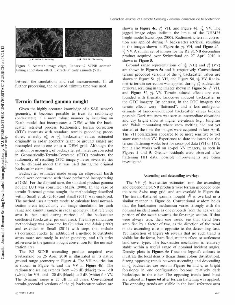
The null cell values at the ‘‘first azimuth’’ edges areillustrated in Figure 3.
The azimuth start time was assigned to the first non-
null cell value line rather than the beginning of the raster
(the timing definition listed in the product format docu-
mentation). No other adjustments were made to the state
vector or radar timing annotation information. Given the
above simple adjustment, good correspondence was found
Figure 1. R2 Ultra-fine geolocation tests using corner reflectors,
(a) U14 ascending 2 March 2010 and (b) U72 descending 10
April 2010.
Figure 2. Radarsat-2 SCNB 26 April 2010 ascending ground
range images, (a) image simulation, (b) gE0 VV backscatter
measurement (black, �20 dB; white, 5 dB).
Vol. 37, No. 5, October/octobre 2011
494 # 2012 CASI
Can
adia
n Jo
urna
l of
Rem
ote
Sens
ing
Dow
nloa
ded
from
pub
s.ca
si.c
a by
HA
UPT
BIB
LIO
TH
EK
UN
IVE
RSI
TA
ET
ZU
ER
ICH
on
03/2
1/12
For
pers
onal
use
onl
y.
between the simulations and real measurements. In all
further processing, the adjusted azimuth time was used.
Terrain-flattened gamma nought
Given the highly accurate knowledge of a SAR sensor’s
geometry, it becomes possible to treat its radiometry
(backscatter) in a more robust manner by including anEarth model that incorporates a DEM within the back-
scatter retrieval process. Radiometric terrain correction
(RTC) contrasts with standard terrain geocoding proce-
dures, whereby r0E or c0
E backscatter values estimated
originally in radar geometry (slant or ground range) are
resampled one-to-one onto a DEM grid. Although the
position, or geometry, of backscatter estimates are corrected
in Geometrically-Terrain-Corrected (GTC) products, theradiometry of resulting GTC imagery never severs its ties
to the ellipsoid model that was used during the original
backscatter estimation.
Backscatter estimates made using an ellipsoidal Earth
model were contrasted with those performed incorporating
a DEM. For the ellipsoid case, the standard product gamma
nought LUT was consulted (MDA, 2008). In the case of
terrain-flattened gamma nought, the methodology describedwithin Small et al. (2010) and Small (2011) was employed.
The method uses a terrain model to calculate local normal-
ization areas individually via image simulation for each
range and azimuth sample in radar geometry. That reference
area is then used during retrieval of the backscatter
coefficient (backscatter per unit area). The image simulation
methodology was pioneered by Guindon and Adair (1992)
and extended in Small (2011) with steps that include(i) occlusion checks, (ii) addition of a method to distribute
areas more accurately in radar geometry, and (iii) strict
adherence to the gamma nought convention for the normal-
ization area.
The R2 SCNB ascending product acquired over
Switzerland on 26 April 2010 is illustrated in its native
ground range geometry in Figure 4. The VH polarization
is shown in Figure 4a and the VV in Figure 4b). Theradiometric scaling extends from �26 dB (black) to �1 dB
(white) for VH, and �20 dB (black) to 5 dB (white) for VV.
The dynamic range is 25 dB in all cases. Conventional
terrain-geocoded versions of the c0E backscatter values are
shown in Figure 4c, c0E VH, and Figure 4d, c0
E VV. The
jagged image edges indicate the limits of the DHM25
height model (swisstopo, 2005). Radiometric terrain correc-
tion was applied during c0T backscatter retrieval, resulting
in the images shown in Figure 4e, c0T VH, and Figure 4f,
c0T VV. A similar set of images for the R2 SCNB descending
product acquired over Switzerland on 27 April 2010 is
shown in Figure 5.
Ground range representations of c0E (VH) and c0
E (VV)
are shown in Figures 5a and b, respectively. Conventional
terrain geocoded versions of the c0E backscatter values are
shown in Figure 5c, c0E VH, and Figure 5d, c0
E VV. Radio-metric terrain correction was applied during c0
T backscatter
retrieval, resulting in the images shown in Figure 5e, c0T VH,
and Figure 5f, c0T VV. Terrain-induced effects are con-
founded with thematic landcover induced backscatter in
the GTC imagery. By contrast, in the RTC imagery the
terrain effects were ‘‘flattened’’, and a less ambiguous
estimate of landcover-induced backscatter values became
possible. Dark wet snow was seen at intermediate elevationsand dry bright snow at higher elevations (e.g., Jungfrau
and Valais mountains) where snow melting had not yet
started at the time the images were acquired in late April.
The VH polarization appeared to be more sensitive to wet
snow cover than VV. Experience to date indicates that the
terrain flattening works best for cross-pol data (VH or HV),
but it also works well on co-pol VV imagery, as seen in
Figures 4 and 5. Greater residuals were observed afterflattening HH data, possible improvements are being
investigated.
Ascending and descending overlays
The VH c0E backscatter estimates from the ascending
and descending SCNB products were terrain geocoded onto
the same Swiss map grid, and are overlaid in Figure 6a.The terrain-flattened gamma nought gT
0 is overlaid in a
similar manner in Figure 6b. Conventional wisdom holds
that the backscatter mechanism varies strongly with the
nominal incident angle as one proceeds from the near-range
portion of the swath towards the far-range section. If that
were always true, then one would see that trend here
amplified by a factor of two, as the direction of the trend
in the ascending case is opposite to the descending case.Yet inspection of Figure 6b reveals that no such trend is
visible for the forest, bare field, water surface, or settlement
land cover types. The backscatter mechanism is relatively
stable within a useful range of nominal incident angles.
Density plots in Figures 6c�f use the legend’s colours to
illustrate the local density (logarithmic colour distribution).
Strong opposing trends between ascending and descending
in c0E backscatter are seen in Figures 6a and c, as bright
foreslopes in one configuration become relatively dark
backslopes in the other. The opposing trends (and bias)
are calmed in Figure 6d after terrain flattening was applied.
The opposing trends are visible in the local reference area
Figure 3. Azimuth image edges, Radarsat-2 SCNB azimuth
timing annotation offset. Extracts at early azimuth (VH).
Canadian Journal of Remote Sensing / Journal canadien de teledetection
# 2012 CASI 495
Can
adia
n Jo
urna
l of
Rem
ote
Sens
ing
Dow
nloa
ded
from
pub
s.ca
si.c
a by
HA
UPT
BIB
LIO
TH
EK
UN
IVE
RSI
TA
ET
ZU
ER
ICH
on
03/2
1/12
For
pers
onal
use
onl
y.
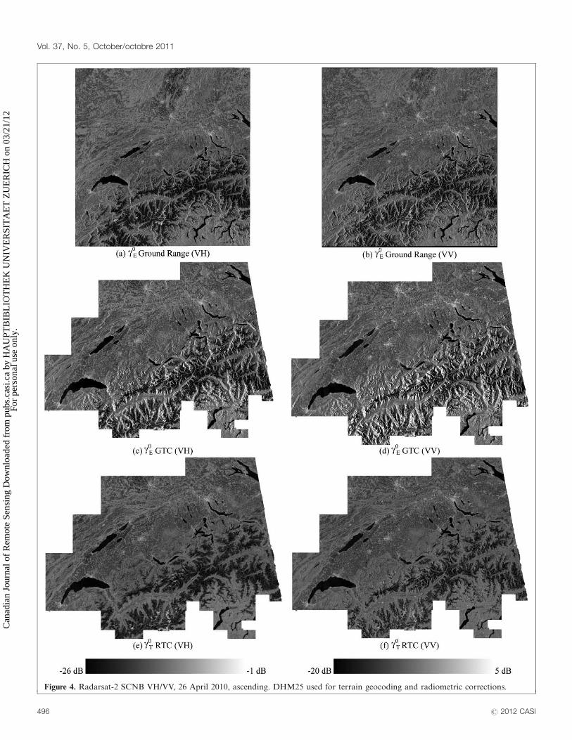
Figure 4. Radarsat-2 SCNB VH/VV, 26 April 2010, ascending. DHM25 used for terrain geocoding and radiometric corrections.
Vol. 37, No. 5, October/octobre 2011
496 # 2012 CASI
Can
adia
n Jo
urna
l of
Rem
ote
Sens
ing
Dow
nloa
ded
from
pub
s.ca
si.c
a by
HA
UPT
BIB
LIO
TH
EK
UN
IVE
RSI
TA
ET
ZU
ER
ICH
on
03/2
1/12
For
pers
onal
use
onl
y.
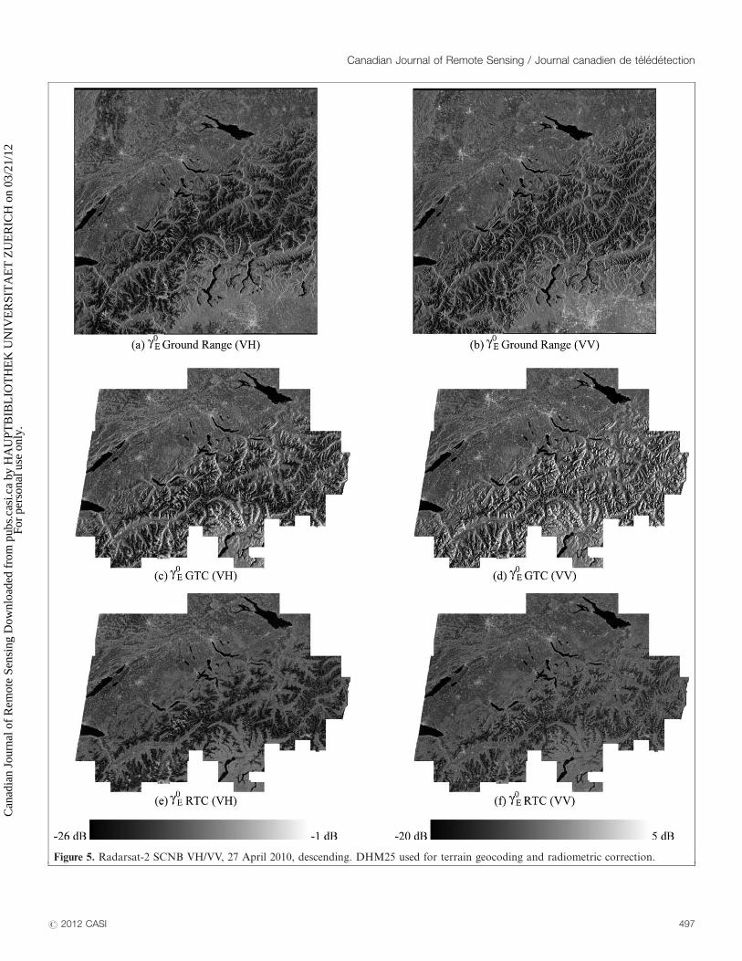
Figure 5. Radarsat-2 SCNB VH/VV, 27 April 2010, descending. DHM25 used for terrain geocoding and radiometric correction.
Canadian Journal of Remote Sensing / Journal canadien de teledetection
# 2012 CASI 497
Can
adia
n Jo
urna
l of
Rem
ote
Sens
ing
Dow
nloa
ded
from
pub
s.ca
si.c
a by
HA
UPT
BIB
LIO
TH
EK
UN
IVE
RSI
TA
ET
ZU
ER
ICH
on
03/2
1/12
For
pers
onal
use
onl
y.

factors of Figure 6e for the two configurations (ascending
and descending). Figure 6f shows that terrain-flattened
gamma nought is flat with respect to the local incident
angle, a result consistent with that reported for more
homogenous land cover in Small et al. (2010) and Small
(2011). The dark areas near the 408 incident angle are
caused by water bodies; the bright areas at the same angles
are caused by settlements. Ensuring that backscatter retrie-
vals become flat with respect to the incident angle requires
that one not use the incident angle to directly determine
the local reference area (e.g,. Kellndorfer et al., 1998).
The reasons are described in Small et al. (2009b). One
should instead use the more robust image simulation
approach described in Small (2011).
Conclusions
The geolocation accuracies achieved without any refine-
ment using tie points were reported for a set of two pairs
Figure 6. Radarsat-2 SCNB over Switzerland, ascending and descending comparisons. (a) gE0 VH GTC, (b) gT
0 VH RTC, (c) VH gE0
A vs. D density, (d) VH gT0 A vs. D density, (e) A vs. D local normalisation area factor, (f) Descending VH gT
0 vs. local incident angle.
Vol. 37, No. 5, October/octobre 2011
498 # 2012 CASI
Can
adia
n Jo
urna
l of
Rem
ote
Sens
ing
Dow
nloa
ded
from
pub
s.ca
si.c
a by
HA
UPT
BIB
LIO
TH
EK
UN
IVE
RSI
TA
ET
ZU
ER
ICH
on
03/2
1/12
For
pers
onal
use
onl
y.
of R2 ultrafine and ScanSAR narrow products. Accurate
tiepoint-free geolocation expedited treatment of terrain
influences during backscatter retrieval, enabling multitrack
backscatter comparisons, even ascending versus descendingbackscatter estimates in Alpine terrain. The narrow Scan-
SAR mode SCNB from R2 provided the closest approx-
imant to the types of products that will become available
from the Sentinel-1a and -1b satellites in the near future.
The VH polarization appeared to be more sensitive to
wet snow cover than the VV polarization. Terrain-flattened
gamma nought products showed great potential for map-
ping dynamic wet snow cover in hilly and mountainousareas. They will improve comparability between multitrack
backscatter estimates within the Sentinel-1 and Radarsat
Constellation Missions (RCM), as well as between them. The
terrain-flattened gamma nought backscatter standard would
enable a theoretical near-worldwide 1 day revisit for the
purposes of backscatter estimation given the availability of
the planned Sentinel-1 and RCM satellites.
Acknowledgements
This work was supported in part by the European
Space Agency under ESRIN/Contract No. 22501/09/I-EC.
The Radarsat-2 data was provided by the Canadian SpaceAgency through its SOAR programme (project 1985).
RADARSAT-2 Data and Products # MacDONALD,
DETTWILER AND ASSOCIATES LTD. (2010) - All
Rights Reserved. The digital height model DHM25 from
swisstopo was used for terrain geocoding and radiometric
corrections.
ReferencesESA, 2007. Information on ALOS PALSAR Products for ADEN Users.
Frascati, Italy, ALOS-GSEG-EOPG-TN-07-0001. April 5, 2007.
Guindon, B., and Adair, M. 1992. Analytic formulation of spaceborne
SAR image geocoding and ‘‘value-added’’ product generation proce-
dures using digital elevation data, Canadian Journal of Remote Sensing,
Vol. 18, pp. 2�12.
Kellndorfer, J.M., Pierce, M., Dobson, C., and Ulaby, F. 1998. Toward
consistent regional-to-global-scale vegetation characterization using
orbital SAR systems, IEEE Transactions on Geoscience and Remote
Sensing, Vol. 36, No. 5, pp. 1396�1410. doi: 10.1109/36.718844.
MDA, Radarsat-2 Product Format Definition, RN-RP-51-2713, Issue 1/7,
14 March 2008, p. 5�40.
Meier, E., Frei, U., and Nuesch, D. 1993. Precise terrain corrected
geocoded images, In: SAR Geocoding: Data and Systems, Schreier G.
(Ed.), Herbert Wichmann Verlag, Germany, pp. 173�185.
Raney, K., Freeman, A., Hawkins, B., and Bamler, R. 1994. A plea
for radar brightness, Proceedings of International Geoscience and
Remote Sensing Symposium IGARSS, Pasadena, Calif., pp. 1090�1092.
doi: 10.1109/IGARSS.1994.399352.
Rosich, B., and Meadows, P. 2004. Absolute calibration of ASAR Level 1
products generated with PF-ASAR, ENVI-CLVL-EOPG-TN-03-0010,
Issue 1, Revision 5.
Schubert, A., Jehle, M., Small, D., and Meier, E. 2010. Influence of
atmospheric path delay on the absolute geolocation accuracy of
TerraSAR-X high-resolution products, IEEE Transactions on Geoscience
and Remote Sensing, Vol. 48, No. 2, pp. 751�758. doi: 10.1109/TGRS.
2009.2036252.
Small, D., Biegger, S., and Nuesch, D. 2000. Automated tiepoint
retrieval through heteromorphic image simulation for spaceborne SAR
sensors, Proceedings of ESA ERS-ENVISAT Symposium, Gothenburg,
Sweden, 16�20 October 2000.
Small, D., Jehle, M., Meier, E., and Nuesch, D. 2004. Radiometric
terrain correction incorporating local antenna gain, Proceedings of the
5th European Conference on Synthetic Aperture Radar EUSAR,
Ulm, Germany, 25�27 May 2004.
Small, D., Rosich, B., Schubert, A., Meier, E., and Nuesch, D. 2004.
Geometric validation of low and high-resolution ASAR imagery,
Proceedings of ENVISAT & ERS Symposium, Salzburg, Austria, 6�10
September 2004, ESA SP-572, 9 p.
Small, D., Miranda, N., and Meier, E. 2009a. A revised radiometric
normalization standard for SAR, Proc. IGARSS, Cape Town, South
Africa, 13�17 July 2009, pp. 566�569. doi: 10.1109/IGARSS.2009.
5417439.
Small, D., Miranda, N., and Meier, E. 2009b. Local incidence angle
considered harmful, Proceedings of CEOS SAR 2009 Cal/Val Workshop,
Pasadena, Calif, 17�19 November 2009. Available from http://www.ceos.
org/images/WGCV/SAR/SESSION_2/2009-Session02-0150.pdf (accessed
September 9, 2011)
Small, D., Miranda, N., Zuberbuhler, L., Schubert, A., and Meier, E. 2010.
Terrain-corrected gamma: improved thematic land-cover retrieval
for SAR with robust radiometric terrain correction, Proceedings of
ESA Living Planet Symposium, Bergen, Norway, 28 June � 2 July 2010,
ESA SP-686, 8 p.
Small, D. 2011. Flattening gamma: radiometric terrain correction for
SAR imagery, IEEE Transactions on Geoscience and Remote Sensing,
Vol. 49, No. 8, pp. 3081�3093. doi: 10.1109/TGRS.2011.2120616.
swisstopo, 2005. DHM25: the digital height model of Switzerland
� Product Information, 15 p.
Canadian Journal of Remote Sensing / Journal canadien de teledetection
# 2012 CASI 499
Can
adia
n Jo
urna
l of
Rem
ote
Sens
ing
Dow
nloa
ded
from
pub
s.ca
si.c
a by
HA
UPT
BIB
LIO
TH
EK
UN
IVE
RSI
TA
ET
ZU
ER
ICH
on
03/2
1/12
For
pers
onal
use
onl
y.