Terminal Relay/Terminal SSR G6B-4@@ND/G3S4 to Options for the G6B-4CB, G6B-4@@ND, and G3S4 on page...
13
CSM_G6B-4__ND_G3S4_DS_E_1_1 1 Terminal Relay/Terminal SSR G6B-4@@ND/G3S4 Compact Terminal Relays/Terminal SSRs with four outputs • Easy wiring with separated input/output terminals. • LED operation indicator. • Mounts either on DIN track or with screws. • Special socket used for easy Relay/SSR replacement (except for high-reliability models). • Terminal Relays • Equipped with four G6B Mini-relays that are compact, highly sensitive, and highly resistant to dielectric surges, and that can switch 5 amps of power. • Sealed plastic construction used for relays. • Built-in diode for absorption of coil surges. • UL and CSA certification for standard models (except for high- reliability models). • VDE certification for G6B-4BND/47BND/48BND for 12/24 VDC. • Terminal SSRs • Easy-to-use SSR block that combines four compact G3S SSRs, sockets, and heat sink in one unit. Terminal Relay types G6B-4@@ND Mounted relays: Electromagnetic Relay................................................................. page 2 G3S4 Mounted relays: Solid State Relay ......................................................................... page 8 Common note Options for the G6B-4CB, G6B-4@@ND, and G3S4 ....................................................................... page 12 ■ Mounted relays Relays and SSRs cannot be mounted together. For the most recent information on models that have been certified for safety standards, refer to your OMRON website. Refer to Safety Precautions for All Relays and Safety Precautions on page 7 and 11.
Transcript of Terminal Relay/Terminal SSR G6B-4@@ND/G3S4 to Options for the G6B-4CB, G6B-4@@ND, and G3S4 on page...

CSM_G6B-4__ND_G3S4_DS_E_1_1
1
Terminal Relay/Terminal SSR
G6B-4@@ND/G3S4Compact Terminal Relays/Terminal SSRs with four outputs
• Easy wiring with separated input/output terminals.• LED operation indicator.
• Mounts either on DIN track or with screws.
• Special socket used for easy Relay/SSR replacement (except for high-reliability models).
• Terminal Relays• Equipped with four G6B Mini-relays that are compact, highly sensitive,
and highly resistant to dielectric surges, and that can switch 5 amps of power.
• Sealed plastic construction used for relays.
• Built-in diode for absorption of coil surges.
• UL and CSA certification for standard models (except for high-reliability models).
• VDE certification for G6B-4BND/47BND/48BND for 12/24 VDC.
• Terminal SSRs• Easy-to-use SSR block that combines four compact G3S SSRs,
sockets, and heat sink in one unit.
Terminal Relay typesG6B-4@@ND Mounted relays: Electromagnetic Relay.................................................................page 2
G3S4 Mounted relays: Solid State Relay.........................................................................page 8
Common noteOptions for the G6B-4CB, G6B-4@@ND, and G3S4 .......................................................................page 12
■ Mounted relaysRelays and SSRs cannot be mounted together.
For the most recent information on models that have been certified for safety standards, refer to your OMRON website.
Refer to Safety Precautions for All Relays and Safety Precautions on page 7 and 11.
2
Terminal Relay
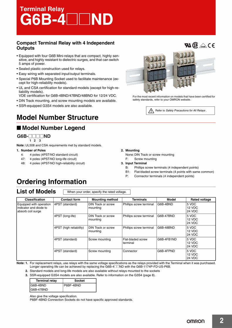
G6B-4@@NDCompact Terminal Relay with 4 Independent Outputs
• Equipped with four G6B Mini-relays that are compact, highly sen-sitive, and highly resistant to dielectric surges, and that can switch 5 amps of power.
• Sealed plastic construction used for relays.• Easy wiring with separated input/output terminals.
• Special P6B Mounting Socket used to facilitate maintenance (ex-cept for high-reliability models).
• UL and CSA certification for standard models (except for high-re-liability models).VDE certification for G6B-4BND/47BND/48BND for 12/24 VDC.
• DIN Track mounting, and screw mounting models are available.
• SSR-equipped G3S4 models are also available.
Model Number Structure■ Model Number Legend
Note: UL508 and CSA requirements met by standard models.
1. Number of Poles4: 4 poles (4PST-NO standard circuit)47: 4 poles (4PST-NO long-life circuit)48: 4 poles (4PST-NO high-reliability circuit)
2. MountingNone: DIN Track or screw mountingF: Screw mounting
3. Input TerminalB: Phillips screw terminals (4 independent points)B1: Flat-bladed screw terminals (4 points with same common)P: Connector terminals (4 independent points)
Ordering InformationList of Models
Note: 1. For replacement relays, use relays with the same voltage specifications as the relays provided with the Terminal when it was purchased.Longer operating life can be achieved by replacing the G6B-4@@ND with the G6B-1174P-FD-US-P6B.
2. Standard models and long-life models are also available without relays mounted to the sockets3. SSR-equipped G3S4 models are also available. Refer to information on the G3S4 (page 8).
Also give the voltage specification. P6BF-4BND Connection Sockets do not have specific approved standards.
For the most recent information on models that have been certified for safety standards, refer to your OMRON website.
Refer to Safety Precautions for All Relays .
1 2 3G6B-@@@@ND
Classification Contact form Mounting method Terminals Model Rated voltage
Equipped with operation indicator and diode to absorb coil surge
4PST (standard) DIN Track or screw mounting
Phillips screw terminal G6B-4BND 5 VDC12 VDC24 VDC
4PST (long-life) DIN Track or screw mounting
Phillips screw terminal G6B-47BND 5 VDC12 VDC24 VDC
4PST (high reliability) DIN Track or screw mounting
Phillips screw terminal G6B-48BND 5 VDC12 VDC24 VDC
4PST (standard) Screw mounting Flat-bladed screw terminal
G6B-4FB1ND 5 VDC12 VDC24 VDC
4PST (standard) Screw mounting Connector G6B-4FPND 5 VDC12 VDC24 VDC
Terminal relay Socket
G6B-4BNDG6B-47BND
P6BF-4BND
When your order, specify the rated voltage.

3
G6B-4@@ND
Specifications
■ Ratings
Coil Ratings (per G6B Relay)
Note: 1. Rated current and coil resistance were measured at a coil temperature of 23°C with a tolerance of ±10%.2. Operating characteristics were measured at a coil temperature of 23°C.3. The maximum allowable voltage is the maximum value of the allowable voltage range for the relay coil operating power supply. There is
no continuous allowance.4. Diodes to absorb coil surge are equivalent to S5688J (reverse voltage resistance: 600 V; forward current: 1 A).5. The values in parentheses are for the G6B-4FB1ND and G6B-4FPND.6. The rated current includes the LED current.
Contact Ratings
Note: This value fulfills the P reference value of opening/closing at a rate of 120 times per min (ambient operating environment and determinationcriteria according to JIS C5442).
■ Characteristics
Note: 1. The above values are initial values.2. Measurement condition: 1 A at 5 VDC
Rated voltage 5 VDC 12 VDC 24 VDC
Rated current 35.5 mA (43.4) 19.1 mA 10.7 mA (10.3)
Coil resistance 125 Ω 720 Ω 2,880 ΩMust operate voltage 80% max. of rated voltage
Must release voltage 10% min. of rated voltage
Max. voltage 130% of rated voltage
Power consumption Approx. 200 mW
Classification G6B-4BND (standard), G6B-47BND (long-life) G6B-48BND (high-reliability)
Load Resistive load (cosφ = 1)
Inductive load (cosφ = 0.4, L/R = 7 ms)
Resistive load (cosφ = 1)
Inductive load (cosφ = 0.4, L/R = 7 ms)
Rated load 5 A at 250 VAC, 5 A at 30 VDC
2 A at 250 VAC, 2 A at 30 VDC
2 A at 250 VAC, 2 A at 30 VDC
0.5 A at 250 VAC, 0.5 A at 30 VDC
Rated carry current 5 A 2 A
Max. switching voltage 380 VAC, 125 VDC
Max. switching current 5 A 2 A
Max. switching power 1,250 VA, 150 W 500 VA, 60 W 500 VA, 60 W 125 VA, 15 W
Error rate (reference value) (see note) 10 mA at 5 VDC 1 mA at 1 VDC
Contact resistance (see note 2) 100 mΩ max.
Operate time 10 ms max. (approx. 3 ms)
Release time 15 ms max. (approx. 4 ms)
Insulation resistance 1,000 MΩ min. (at 500 VDC)
Dielectric strength 2,000 VAC, 50/60 Hz for 1 min between coil and contacts2,000 VAC, 50/60 Hz for 1 min between contacts of different polarity1,000 VAC, 50/60 Hz for 1 min between contacts of same polarity250 VAC, 50/60 Hz for 1 min between coils of different polarity
Vibration resistance Destruction: 10 to 55 to 10 Hz, 0.75-mm single amplitude (1.5-mm double amplitude)Malfunction: 10 to 55 to 10 Hz, 0.75-mm single amplitude (1.5-mm double amplitude)
Shock resistance Destruction: 1,000 m/s2 (approx. 100G)Malfunction: 100 m/s2 (approx. 10G)
Endurance Mechanical: 50,000,000 operations min. (at 18,000 operations/hr)Electrical: 100,000 operations min. (at 1,800 operations/hr, rated load)
500,000 operations min. for long-life at 2 A100,000 operations min for long-life at 5 A
Ambient temperature Operating: –25°C to 55°C (with no icing or condensation)Storage: –25°C to 55°C (with no icing or condensation)
Ambient humidity Operating: 35% to 85%
Weight Approx. 75 g

G6B-4@@ND
4
Engineering Data
Note: Measurement values taken from production line samples have been plotted in graphs to provide this data. Use this data only as a guide.Relays are mass-produced, so allowances must be made for a certain amount of variation in measurement data.
4,000
1,000
500
300
100
� Endurance
Sw
itchi
ng c
urre
nt (
A)
End
uran
ce (
x103
oper
atio
ns)
Switching voltage (V) Switching current (A)
Con
tact
res
ista
nce
(m
Ω)
AC resistive load
DC resistive load
G6B-4@ (standard)
� Contact Reliability (High-reliability Models)
AC inductive load (cosφ = 0.4)
DC inductive load (L/R = 7 ms)
G6B-47@ (long life) 250 VAC resistive load 30 VDC resistive load
250 VAC resistive load 30 VDC resistive load
G6B-4@ (standard)G6B-47@ (long-life) 250 VAC inductive load (cosφ = 0.4) 30 VDC inductive load (L/R = 7 ms) G6B-48@ (high-reliability) 250 VAC resistive load 30 VDC resistive load
� Maximum Switching Power
Number of switching operations (×104 times)

5
G6B-4@@ND
DimensionsNote: All units are in millimeters unless otherwise indicated.
Philip Screw Terminals
Note: G6B-4BND is shown in illustration (terminal numbers are incised).
Mounting Holes(Top View)
Flat Screw TerminalG6B-4FB1ND
Mounting Holes(Top View)
Connector TerminalG6B-4FPND
Mounting Holes(Top View)
Note: Do not reverse the coil polarity.
16, M3.5 Phillips head screws
IN side
43 max. 28 max.
78 max.
IN side
OUT side
IN side
43 max.
61 max.
24 max.
Five, M2.6 flat screws
IN side
OUT side
IN side
43 max.
60 max.
Note: Do not reverse the coil polarity.
Note: Do not reverse the coil polarity.
G6B-4BND G6B-47BND G6B-48BND
Operation indicator
OUT side
Terminal Arrangement/ Internal Connections (Top View)
Operation indicator
OUT side
Eight, M3.5 Phillips head screws
Terminal Arrangement/ Internal Connections (Top View)
Terminal Arrangement/ Internal Connections (Top View)
Eight, M3.5 Phillips head screws
Operation indicator
OUT side
24 max.
Two, 4-dia. holes or M3.5 screw holes
Two, 4-dia. holes or M3.5 screw holes
Two, 4-dia. holes or M3.5 screw holes
34.5±0.2
50±0.3
1216
1115
1014
913
1
8 7 6 45 3 2 1
− + +
2
+−
3
− +
4
−
50±0.3
34.5±0.2
IN side
OUT side
1216
1115
1014
913
1 2 3 4
5 4 3 2 1
− − − − + COM
65±0.3
36±0.2
9
84
1310
1411
1512
16
−
+
1
73
−
+
2
62
−
+
3
51
−
+
4
(30 max. for G6B-47@@ long-life model)
2 3 41
2 3 41
2 3 41
6
G6B-4@@ND
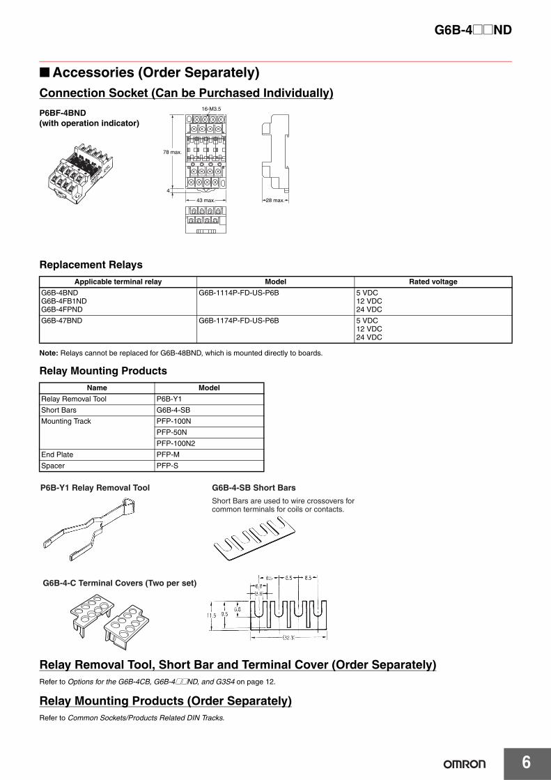
■ Accessories (Order Separately)
Replacement Relays
Note: Relays cannot be replaced for G6B-48BND, which is mounted directly to boards.
Relay Mounting Products
Relay Removal Tool, Short Bar and Terminal Cover (Order Separately)Refer to Options for the G6B-4CB, G6B-4@@ND, and G3S4 on page 12.
Relay Mounting Products (Order Separately)Refer to Common Sockets/Products Related DIN Tracks.
Applicable terminal relay Model Rated voltage
G6B-4BNDG6B-4FB1NDG6B-4FPND
G6B-1114P-FD-US-P6B 5 VDC12 VDC24 VDC
G6B-47BND G6B-1174P-FD-US-P6B 5 VDC12 VDC24 VDC
Name Model
Relay Removal Tool P6B-Y1
Short Bars G6B-4-SB
Mounting Track PFP-100N
PFP-50N
PFP-100N2
End Plate PFP-M
Spacer PFP-S
28 max.43 max.
78 max.
16-M3.5
4
Connection Socket (Can be Purchased Individually)
P6BF-4BND(with operation indicator)
P6B-Y1 Relay Removal Tool G6B-4-SB Short Bars
Short Bars are used to wire crossovers for common terminals for coils or contacts.
G6B-4-C Terminal Covers (Two per set)

G6B-4@@ND
7
Safety PrecautionsRefer to Safety Precautions for All Relays.
WiringBe sure to turn OFF the power when wiring the Unit and do not touchthe charged terminals of the Unit. Otherwise, an electric shock mayresult.Do not apply overvoltage to the input terminals. Otherwise, the Unitmay malfunction or burn.
Relay ModelsDo not connect the Unit to loads exceeding the rated switching power(switching voltage or current). Otherwise, faulty insulation, contactweld, or faulty contact of Relays, or damage to Relays may result, orthe Relays may malfunction or burn.The life of Relays varies with the switching condition. Test the Relaysunder the actual operating conditions before using the Relays withinthe permissible switching frequency. The use of deteriorated Relaysmay result in the faulty insulation of the Relays or cause the Relaysto burn.Do not use the Unit in locations with inflammable gas. Otherwise, afire or explosion due to the heat of the Relays or sparks from theRelays may result when they are switched.
■ Correct Use
MountingHeat generated by the relays must be considered when gang-mount-ing. Space must be provided between the relays or other methodsmust be taken to maintain the relays’ ambient temperature at 55 °Cor lower.
Replacement of Relays
G6B-4@@NDUse the P6B-Y1 Removal Tool as shown in the following diagram.
Be sure to turn OFF the power to the Unit before replacing a Relay.Relays must be inserted straight onto the socket connector pins toensure proper connection.G6B-48BND models (high reliability) are connected directly toboards to increase reliability and the relays are thus not replaceable.If relay replacement is necessary, use the P6BF-4BND TerminalSockets together with the G6B-1184P Mini Relays. P6BF-4BND Ter-minal Sockets are equipped with relay replacement sockets.Do not mount Relays that are different to one another in voltage.
Relays MountedG6B-4@@ND standard: G6B-1114P-FD-US-P6BG6B-4@@ND long life: G6B-1174P-FD G6B-4@@ND high reliability: G6B-1184P-US Replacement is not possible for G6B-48BND.
Mounted RelaysRelays and SSRs cannnot be mounted together.
WiringBe sure to connect the input terminals with the correct polarity.
Coil VoltageBe sure not to impose voltage exceeding the permissible voltage onthe coil continuously.Do not use the relays when other inductive loads are connected inparallel with the coil input or when there are surges during powersupply because the built-in diodes used to absorb surge may bedestroyed.
Do Not Use the Following Circuit
HandlingDo not drop, shock, or vibrate the Unit excessively. Otherwise, dam-age to the Unit may result or the Unit may malfunction.Make sure that all the Relays are properly mounted before use.
Screw Tightening TorqueTighten each terminal screw to a torque described below.M3 terminal screw: 0.4 to 0.56 N·m.M3.5 terminal screw: 0.78 to 1.18 N·m.Tighten each mounting screw to a torque of 0.59 to 0.98 N·m.
Installation EnvironmentDo not install the Unit in the following locations. Otherwise, damageto the Unit may result or the Unit may malfunction.Locations with direct sunlight.Locations with an ambient temperature range not within 0°C to 55°C.Locations with rapid temperature changes resulting in condensationor locations with relative humidity ranges not within 10% to 90%.Locations with corrosive or inflammable gas.Locations with excessive dust, salinity, or metal powder.Locations with vibration or shock affecting the Unit.Locations with water, oil, or chemical sprayed on the Unit.
Disassembly, Repair, and ModificationDo not disassemble, repair, or modify the Unit. Otherwise, an electricshock may result or the Unit may malfunction.
Inductive load G6B Coil Coil surge current absorption diode
In the interest of product improvement, specifications are subject to change without notice.
ALL DIMENSIONS SHOWN ARE IN MILLIMETERS.
To convert millimeters into inches, multiply by 0.03937. To convert grams into ounces, multiply by 0.03527.
8
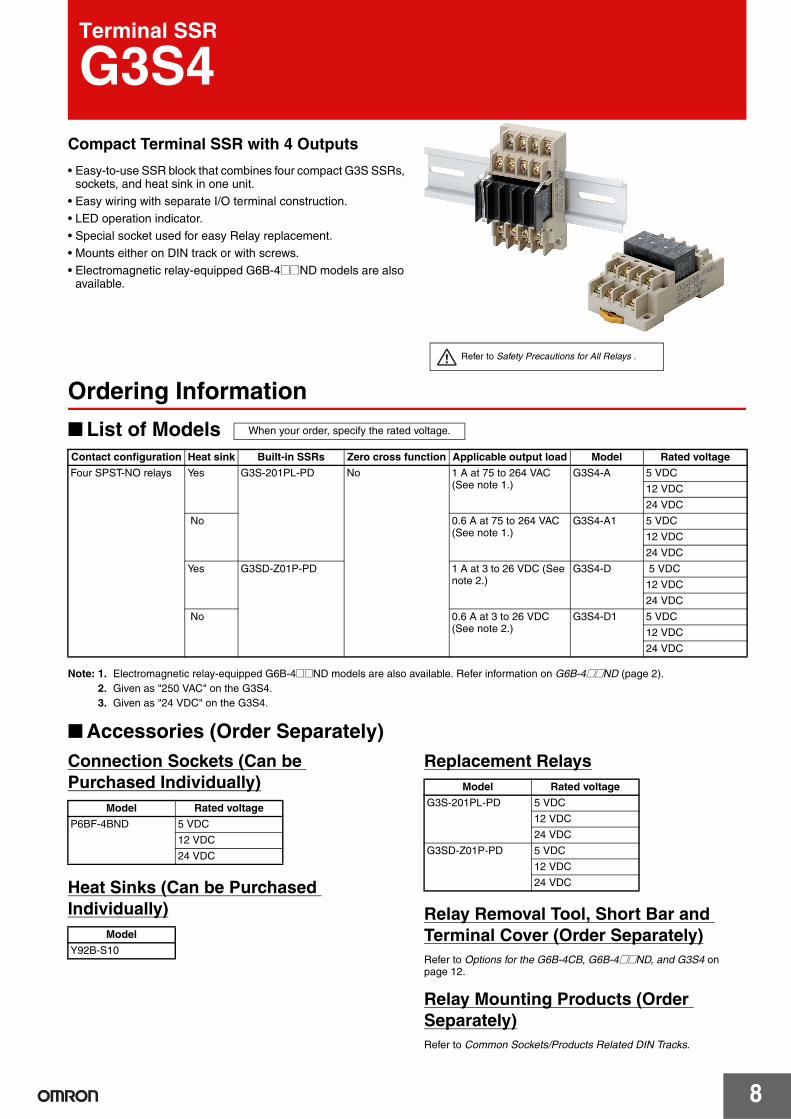
Terminal SSR
G3S4Compact Terminal SSR with 4 Outputs
• Easy-to-use SSR block that combines four compact G3S SSRs, sockets, and heat sink in one unit.
• Easy wiring with separate I/O terminal construction.
• LED operation indicator.• Special socket used for easy Relay replacement.
• Mounts either on DIN track or with screws.
• Electromagnetic relay-equipped G6B-4@@ND models are also available.
Refer to Safety Precautions for All Relays .
Ordering Information
■ List of Models
Note: 1. Electromagnetic relay-equipped G6B-4@@ND models are also available. Refer information on G6B-4@@ND (page 2).2. Given as "250 VAC" on the G3S4.3. Given as "24 VDC" on the G3S4.
■ Accessories (Order Separately)Connection Sockets (Can be Purchased Individually)
Heat Sinks (Can be Purchased Individually)
Replacement Relays
Relay Removal Tool, Short Bar and Terminal Cover (Order Separately)Refer to Options for the G6B-4CB, G6B-4@@ND, and G3S4 on page 12.
Relay Mounting Products (Order Separately)Refer to Common Sockets/Products Related DIN Tracks.
Contact configuration Heat sink Built-in SSRs Zero cross function Applicable output load Model Rated voltage
Four SPST-NO relays Yes G3S-201PL-PD No 1 A at 75 to 264 VAC (See note 1.)
G3S4-A 5 VDC
12 VDC
24 VDC
No 0.6 A at 75 to 264 VAC (See note 1.)
G3S4-A1 5 VDC
12 VDC
24 VDC
Yes G3SD-Z01P-PD 1 A at 3 to 26 VDC (See note 2.)
G3S4-D 5 VDC
12 VDC
24 VDC
No 0.6 A at 3 to 26 VDC (See note 2.)
G3S4-D1 5 VDC
12 VDC
24 VDC
When your order, specify the rated voltage.
Model Rated voltage
P6BF-4BND 5 VDC
12 VDC
24 VDC
Model
Y92B-S10
Model Rated voltage
G3S-201PL-PD 5 VDC
12 VDC
24 VDC
G3SD-Z01P-PD 5 VDC
12 VDC
24 VDC

G3S4
9
Specifications
■ RatingsInput (per G3S Relay)
Note: The rated current includes the terminal's LED current.
Output (per G3S Relay)
■ Characteristics
Engineering Data
■ Reference Data
Note: Measurement values taken from production line samples have been plotted in graphs to provide this data. Use this data only as a guide.Relays are mass-produced, so allowances must be made for a certain amount of variation in measurement data.
Rated voltage
Operating voltage
Must operate level
Must release voltage level
Input impedance Rated current
G3S4-A, G3S4-A1
G3S4-D, G3S4-D1
G3S4-A, G3S4-A1
G3S4-D, G3S4-D1
DC 5 V 4 to 6 VDC 4 VDC max. 1 VDC min. 440 Ω±20% 550 Ω±20% 19.2 mA±20% 15.8 mA±20%
12 V 9.6 to 14.4 VDC 9.6 VDC max. 1 kΩ±20% 1.2 kΩ±20% 15.8 mA±20% 12.5 mA±20%
24 V 19.2 to 28.8 VDC 19.2 VDC max. 2.1 kΩ±20% 2.3 kΩ±20% 15.7 mA±20% 13.2 mA±20%
Model Applicable load Load voltage Load current Inrush current resistance
G3S4-A 75 to 264 VAC 0.1 to 1 A 15 A (60 Hz, 1 cycle)
G3S4-A1 0.1 to 0.6 A
G3S4-D 3 to 26 VDC 0.01 to 1 A 3 A (10 ms)
G3S4-D1 0.01 to 0.6 A
Item Model G3S4-A, G3S4-A1 G3S4-D, G3S4-D1
Must operate time 1 ms max.
Release time 0.5 × load power cycle + 1 ms max. 1 ms max.
Output ON voltage drop 1.6 V max. (RMS) 1.5 V max.
Leakage current 2 mA max. 0.1 mA max. (at 26 VDC)
Insulation resistance 100 MΩ min. (at 500 VDC)
Dielectric strength 2,000 VAC, 50/60 Hz for 1 min
Vibration resistance 10 to 55 to 10 Hz, 0.75-mm single amplitude (1.5-mm double amplitude)
Shock resistance 1,000 m/s2
Storage temperature −30 to 100°C (with no icing)
Ambient operating temperature −30 to 80°C (with no icing)
Ambient operating humidity 45% to 85%
Weight Approx. 95 g (-A model) Approx. 95 g (-D model)
(per G3S Relay)
Load Current vs. Ambient Rated Temperature
Inrush Current ResistanceNon-repetitive (Keep the inrush current to half the rated value if inrush current occurs repetitively.)G3S4-A, G3S4-A1 G3S4-D, G3S4-D1
0.75
0.6
0.5
0.25
0.1
0
1
−30 −20 0 20 40 60 80 100
Ambient temperature (°C)
G3S4-A, G3S4-D
G3S4-A1, G3S4-D1
Load
cur
rent
(A
)
1510
50
10 30 50 100 200 500 1,000 5,000
Energizing time (ms)
Inru
sh c
urre
nt (
A. P
eak)
3210
10 30 50 100 200 500 1,000 5,000
Energizing time (ms)
Inru
sh c
urre
nt (
A. P
eak)
G3S4
10
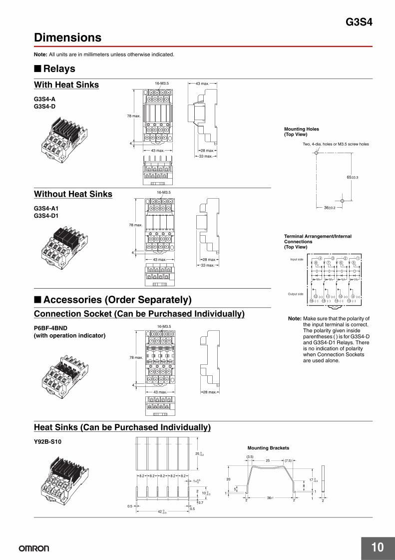
DimensionsNote: All units are in millimeters unless otherwise indicated.
■ Relays
■ Accessories (Order Separately)
With Heat Sinks
G3S4-AG3S4-D
28 max.
33 max.
43 max.
43 max.
78 max.
16-M3.5
4
65±0.3
Two, 4-dia. holes or M3.5 screw holes
36±0.2
Mounting Holes(Top View)
Terminal Arrangement/Internal Connections(Top View)
8 4
12 16
−
+7
3 −
+6
2 −
+5
1 −
+
(+) (−)
11 15
(+) (−)
10 14
(+) (−)
9 13
(+) (−)
Input side
Output side
Note: Make sure that the polarity of the input terminal is correct.The polarity given inside parentheses ( ) is for G3S4-D and G3S4-D1 Relays. There is no indication of polarity when Connection Sockets are used alone.
Without Heat Sinks
G3S4-A1G3S4-D1
28 max.
33 max.
43 max.
78 max.
16-M3.5
4
28 max.43 max.
78 max.
16-M3.5
4
Connection Socket (Can be Purchased Individually)
P6BF-4BND(with operation indicator)
Heat Sinks (Can be Purchased Individually)
Y92B-S10
21
1
8
22
2
0.736±1
51
20
(3.5)25 (7.5)
17 0−0.3
10 0−0.3
25 0−0.2
42 0−0.3
1+0.50
0.50.5
8.28.28.28.28.2
Mounting Brackets

G3S4
11
Safety Precautions Refer to Safety Precautions for All Relays.
■ Precautions for Correct Use• The four SSRs are mounted individually. Use standard SSR
connection methods.• There is almost no differences based on the mounting direction.
Mount the Terminal SSR with the best air flow.• Apply a silicon grease for heat radiation (e.g., YG6260 or G746
from Shin-Etsu Chemical Co. Ltd.) between the heat sink and the SSR if the heat sink is removed during maintenance of the G3S4-A or G3S4-D Terminal SSR (with external heat sinks) or if an external heat sink that was purchased separately is mounted.
• The load voltage cannot be increased by connecting the G3S4 load terminals in serial. This is because there is a small difference in the SSR operating time
• The load current cannot be increased by connecting the G3S4 load terminal in parallel. This is because there is a small difference in the SSR operating time.
• The P6BF-4BND Connection Socket has an operation indicator and is available in 5-VDC, 12-VDC, and 24-VDC models.
• Use the P6B-Y1 Relay Removal Tool to remove SSRs.
Mounted RelaysRelays and SSRs cannot be mounted together.
Input voltage INPUT LOAD
Load (+)
(−)
(−) (+)
Load power supply
−
+
1
6
Replacement Relays
G3S-201PL-PDG3SD-Z01P-PD
Terminal Arrangement/Connections(Bottom View)
4
7.62 7.62
0.8 0.4
10.16
10 max.
16 max. 16.5 max.
20 max.
Note: 1. The polarity given inside parentheses ( ) is for DC loads.
2. The load can be connected to ether the positive or negative SSR output terminal.
Relay Removal Tool and Short Bar (Order Separately)Refer to Options for the G6B-4CB, G6B-4@@ND, and G3S4 on page 12.
Relay Mounting Products (Order Separately)Refer to Common Sockets/Products Related DIN Tracks.

12
Options for the G6B-4CB, G6B-4@@ND, and G3S4Relay Removal ToolP6B-Y1
Short BarG6B-4-SB
Terminal Cover (Two per Set)G6B-4-C
Connection Socket (Can be Purchased Individually)P6BF-4BND (with operation indicator)
Ordering Information
Applicable Terminal Relays Model
G6B-4CBG6B-4@@NDG3S4
P6B-Y1
11.5 9.56.8
(32.3)
8.5 8.5 8.5
3.66.8
A Short Bar is used to wire crossovers for common terminals for coils or contacts. Ordering Information
Applicable Terminal Relays Model
G6B-4CBG6B-4@@NDG3S4
G6B-4-SB
Ordering Information
Applicable Terminal Relays Model
G6B-4BNDG6B-47BNDG6B-48BNDG3S4-A1G3S4-D1
G6B-4-C
28 max.43 max.
78 max.
16-M3.5
4
Ordering Information
Also give the voltage specification. P6BF-4BND Connection Sockets do not have specific approved standards.
Applicable Terminal Relays Model Rated voltage
G6B-4BNDG6B-47BNDG3S4
P6BF-4BND
5 VDC
12 VDC
24 VDC

Terms and Conditions Agreement Read and understand this catalog. Please read and understand this catalog before purchasing the products. Please consult your OMRON representative if you have any questions or comments. Warranties. (a) Exclusive Warranty. Omron’s exclusive warranty is that the Products will be free from defects in materials and workmanship for a period of twelve months from the date of sale by Omron (or such other period expressed in writing by Omron). Omron disclaims all other warranties, express or implied. (b) Limitations. OMRON MAKES NO WARRANTY OR REPRESENTATION, EXPRESS OR IMPLIED, ABOUT NON-INFRINGEMENT, MERCHANTABILITY OR FITNESS FOR A PARTICULAR PURPOSE OF THE PRODUCTS. BUYER ACKNOWLEDGES THAT IT ALONE HAS DETERMINED THAT THE PRODUCTS WILL SUITABLY MEET THE REQUIREMENTS OF THEIR INTENDED USE. Omron further disclaims all warranties and responsibility of any type for claims or expenses based on infringement by the Products or otherwise of any intellectual property right. (c) Buyer Remedy. Omron’s sole obligation hereunder shall be, at Omron’s election, to (i) replace (in the form originally shipped with Buyer responsible for labor charges for removal or replacement thereof) the non-complying Product, (ii) repair the non-complying Product, or (iii) repay or credit Buyer an amount equal to the purchase price of the non-complying Product; provided that in no event shall Omron be responsible for warranty, repair, indemnity or any other claims or expenses regarding the Products unless Omron’s analysis confirms that the Products were properly handled, stored, installed and maintained and not subject to contamination, abuse, misuse or inappropriate modification. Return of any Products by Buyer must be approved in writing by Omron before shipment. Omron Companies shall not be liable for the suitability or unsuitability or the results from the use of Products in combination with any electrical or electronic components, circuits, system assemblies or any other materials or substances or environments. Any advice, recommendations or information given orally or in writing, are not to be construed as an amendment or addition to the above warranty. See http://www.omron.com/global/ or contact your Omron representative for published information. Limitation on Liability; Etc. OMRON COMPANIES SHALL NOT BE LIABLE FOR SPECIAL, INDIRECT, INCIDENTAL, OR CONSEQUENTIAL DAMAGES, LOSS OF PROFITS OR PRODUCTION OR COMMERCIAL LOSS IN ANY WAY CONNECTED WITH THE PRODUCTS, WHETHER SUCH CLAIM IS BASED IN CONTRACT, WARRANTY, NEGLIGENCE OR STRICT LIABILITY. Further, in no event shall liability of Omron Companies exceed the individual price of the Product on which liability is asserted. Suitability of Use. Omron Companies shall not be responsible for conformity with any standards, codes or regulations which apply to the combination of the Product in the Buyer’s application or use of the Product. At Buyer’s request, Omron will provide applicable third party certification documents identifying ratings and limitations of use which apply to the Product. This information by itself is not sufficient for a complete determination of the suitability of the Product in combination with the end product, machine, system, or other application or use. Buyer shall be solely responsible for determining appropriateness of the particular Product with respect to Buyer’s application, product or system. Buyer shall take application responsibility in all cases. NEVER USE THE PRODUCT FOR AN APPLICATION INVOLVING SERIOUS RISK TO LIFE OR PROPERTY OR IN LARGE QUANTITIES WITHOUT ENSURING THAT THE SYSTEM AS A WHOLE HAS BEEN DESIGNED TO ADDRESS THE RISKS, AND THAT THE OMRON PRODUCT(S) IS PROPERLY RATED AND INSTALLED FOR THE INTENDED USE WITHIN THE OVERALL EQUIPMENT OR SYSTEM. Programmable Products. Omron Companies shall not be responsible for the user’s programming of a programmable Product, or any consequence thereof. Performance Data. Data presented in Omron Company websites, catalogs and other materials is provided as a guide for the user in determining suitability and does not constitute a warranty. It may represent the result of Omron’s test conditions, and the user must correlate it to actual application requirements. Actual performance is subject to the Omron’s Warranty and Limitations of Liability. Change in Specifications. Product specifications and accessories may be changed at any time based on improvements and other reasons. It is our practice to change part numbers when published ratings or features are changed, or when significant construction changes are made. However, some specifications of the Product may be changed without any notice. When in doubt, special part numbers may be assigned to fix or establish key specifications for your application. Please consult with your Omron’s representative at any time to confirm actual specifications of purchased Product. Errors and Omissions. Information presented by Omron Companies has been checked and is believed to be accurate; however, no responsibility is assumed for clerical, typographical or proofreading errors or omissions.
2017.4
In the interest of product improvement, specifications are subject to change without notice.
OMRON Corporation Industrial Automation Company http://www.ia.omron.com/
(c)Copyright OMRON Corporation 2017 All Right Reserved.