
TERMINAL PARTICULARS -...
38
TERMINAL PARTICULARS QUESTIONNAIRE Formularz : F14 Wydanie : 001 Data : 30.09.2018 Edytował : AF,TM,PK,PW NAFTOPORT MARINE OIL TERMINAL UPDATED: 09.2018 NEXT PLANNED UPDATE: 08.2019
Transcript of TERMINAL PARTICULARS -...

TERMINAL PARTICULARS
QUESTIONNAIRE
Formularz : F14
Wydanie : 001
Data : 30.09.2018
Edytował : AF,TM,PK,PW
NAFTOPORT MARINE OIL TERMINAL
UPDATED: 09.2018
NEXT PLANNED UPDATE: 08.2019

2
I. GENERAL
1. Date this TPQ document was completed
30.09.2018
2.Specify units used
Meters, metric tons,
II. PORT DETAILS
1.Port Name
Naftoport Marine Oil Terminal Port of Gdansk
2.UN LOCODE
PL GDN
3.Country
Poland
4.Latitude and Longitude of Port
54O24’22.9’’N
18O42’56.5’’E
5.Is this location affected by ice?
Rarely; thickness of ice do not affects navigation
6.Name of port authority
Director of Maritime Authority in Gdynia Kpt. ż.w. Wiesław Piotrzkowski.
7.Port authority contact name and title
Harbour Master Duty Port Officer
8.Port authority full style contact address:
Harbour Master Duty Port Officer
Street: Kpt. ż. w. W. Poinca 1
City: Gdańsk
Country: Polska

3
Zip code: 80-561
Tel: +48(58)343 0710, +48(58)737 7371
Fax: +48(58)737 7512
Email: [email protected]
Website: http://umggdy.gov.pl
Harbour Master – Head office
Street: Przemysłowa 4
City: Gdańsk
Country: Polska
Zip code: 80-542
Tel: +48(58)343 0510, +48(58)343 0610
Fax: +48(58)343 0144
Email: [email protected]
Website: http://umggdy.gov.pl
III. TERMINAL DETAILS
1.Terminal name
Naftoport Marine Oil Terminal
2. Number of berth’s included in this TPQ
TPQ includes five berth’s:
O, P, R, T, T1
3. Terminal owner
NAFTOPORT Limited
4. Name of first point of contact for terminal operator
NAFTOPORT Operations Department / Marine Oil Terminal Dispatcher (24 hrs/day)
Tel: +48(58)343 6655, +48(58)343 7436, +48(58)343 7434, +48(58)343 6434
Fax: +48(58)343 7606, +48(58)343 1025
Email: [email protected]

4
5. Terminal owner / operator full style contact address – main office
Street: Kpt. ż. w. W. Poinca 1
City: Gdańsk
Country: Polska
Zip code: 80-561
Tel: +48(58)343 7425, +48(58)737 7425 ( Head of Office )
Fax: +48(58)343 7606, +48(58)737 7606
Email: [email protected]
Website: www.naftoport.pl
IV. PORT FACILITY SECURITY OFFICER DETAILS
1.Does the port facility comply with the ISPS code?
YES, Port Facility “K” No: PLGDN-0011
2. Port Facility Security Officer contact name:
Mr. Cezary Jóźwiak
3. Port Facility Security Officer full style contact details
Street: Kpt. ż. w. W. Poinca 1
City: Gdańsk
Country: Polska
Zip code: 80-561
Tel: +48 603 242 668, +48 502 193 232, +48(58)343 6765,
Fax: +48(58)343 6765
Email: [email protected]
Website: www.naftoport.pl

5
V. OPERATIONAL INTEGRITY DETAILS
1. State details of any pre-arrival/operational clearance formalities for vessels
It is compulsory to obtain Harbour Master’s permission to enter or leave the port of
Gdansk. To receive the permission for entering/leaving the port, the ship shall contact
Harbour Master's Office and report the ship's name, nationality, length, beam, draught, type
of cargo and other details requested by Harbour Master's Office. The permission to enter /
leave shall be granted by Harbour Master's Office through communication means; VHF
Channel 14 is basic mean of communication.
Master of the ship or agent acting on behalf thereof, before the vessel’s entry into Port of
Gdansk is obliged to provide the Harbour Master (using the Polish Harbour Information &
Control System (PHICS)) with information regarding ship's identification, port of destiny,
estimated time of arrival to the port of destiny and estimated time of departure from the port
and the number of all persons on board:
at least 72 hours before arrival tanker with dangerous cargo or not gas-free
at least 48 hours before arrival gas-free tanker
at least 24 hours before the ship's arrival, or,
not later than at the time when the ship leaves the previous port, if the voyage is
shorter than 24 hours, or,
immediately if the port of destiny is unknown or changes during the voyage.
After arrival at the road, ship's master shall notify by radio Harbour Master's office of the
following:
ship's name, call sign and IMO number,
LOA, beam and draught,
ship's tonnage according to International Tonnage Certificate, London'69,
type and amount of cargo, including dangerous and polluting cargo,
authorized agent,
last port of call.
Immediately after ship's arrival to the port, ship's master or the person authorized by ship's
master shall submit, in a written form, at Harbour master's office Statement of Arrival and
information on dangerous / polluting goods.
On the request of Harbour M aster the Statement of Arrival of a ship in international voyage
shall be accompanied by the originals of the following documents:
Ship's Certificate,
International Measurement Certificate,
6
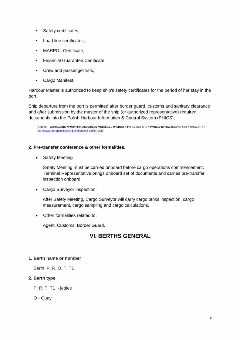
Safety certificates,
Load line certificates,
MARPOL Certificate,
Financial Guarantee Certificate,
Crew and passenger lists,
Cargo Manifest.
Harbour Master is authorized to keep ship's safety certificates for the period of her stay in the
port.
Ship departure from the port is permitted after border guard, customs and sanitary clearance
and after submission by the master of the ship (or authorized representative) required
documents into the Polish Harbour Information & Control System (PHICS).
(Source: - ZARZĄDZENIE Nr 9 DYREKTORA URZĘDU MORSKIEGO W GDYNI z dnia 16 lipca 2018 r. Przepisy portowe (Gdańsk, dnia 7 marca 2013 r.) -
http://www.portgdansk.pl/shipping/vessel-traffic-rules )
2. Pre-transfer conference & other formalities.
Safety Meeting
Safety Meeting must be carried onboard before cargo operations commencement.
Terminal Representative brings onboard set of documents and carries pre-transfer
inspection onboard.
Cargo Surveyor inspection
After Safety Meeting, Cargo Surveyor will carry cargo tanks inspection, cargo
measurement, cargo sampling and cargo calculations.
Other formalities related to:
Agent, Customs, Border Guard.
VI. BERTHS GENERAL
1. Berth name or number
Berth P, R, O, T, T1
2. Berth type
P, R, T, T1 - jetties
O - Quay

7
3. Has a structural survey of the berth been undertaken, including its underwater
structure?
Yes, September 2017 ( every five years )
4. Has an engineering (mooring and fendering) analysis of berth been undertaken?
Yes, September 2017 ( every five years )
5. Additional comments or information
No
VII. BERTH APPROACHES
1. Is pilotage compulsory?
Yes, no exemptions
2. State distance from pilot station(s) to berth
Approx. 6 Nautical Miles
3. Is a waiting anchorage available?
Yes, Anchorage Gdańsk No 5, approx. 4,5 Nautical Miles from Naftoport Oil Terminal
4. Controlling depth of water for transit to and from berth
Jetty P – approach 17 meters, berth 16,50 meters
Jetty R – approach 17 meters, berth 16,50 meters
Jetty O – approach 17 meters, berth 11 meters
Jetty T – approach 17 meters, berth 16,50 meters
Jetty T1 – approach 17 meters, berth 14,0 meters
State datum used – Lowest Astronomical Tide ( LAT )
5. Date of latest survey from which transit depth has been determined
Basin No 1 ( Jetty O,P ) 04.04.2018
Basin No 2 ( Jetty R,T ) 10.05.2018
Basin No 3 ( Jetty T1 ) 27.04.2018
6. Date next survey is due
Annual survey

8
7. State Maximum Tidal Range in berth approaches
Accordingly to 20 years of observation mean tidal range is not greater than approx.. +/- 50
cm and depends on wind direction. Winds from northern to eastern directions raise the sea
level, winds from the western and southern directions lower the sea level.
8. Is laden transit to and/or from the berth conducted using the tide?
N/A
9. State details of any specific berthing and/or unberthing restrictions
Use of propellers and thrusters by manoeuvring tanker should be reduced to minimum
due to submerged anti-spill air barrier installations.
10. Minimum under keel clearance (UKC) in berth approaches
Value – 1,5 meters
Percentage – 10% of the maximum permissible draft
Specify other UKC criterion where applicable:
(Source: - Rozporządzenie Ministra Transportu i Gospodarki Morskiej z dnia 1 czerwca 1998 r. w sprawie warunków technicznych, jakim
powinny odpowiadać morskie budowle hydrotechniczne i ich usytuowanie, Dziennik Ustaw 101,poz.645, paragraf 28 pkt 5. - Captain’s of the
Port requirements)
11. Absolute maximum draught in berth approaches, if applicable
Jetty P – 15,00 m
Jetty R – 15,00 m
Jetty O – 10,00 m
Jetty T – 15,00 m
Jetty T1 – 12,7 m
See “Atlas of maximum Authorized Drafts at the Port Of Gdansk” on web site : http://www.umgdy.gov.pl/?page_id=1514 Last update
18.09.2018
12. State minimum vertical clearance of any bridges/power cables/vertical
obstructions
No bridges, power cables or other vertical obstructions on approach.
13. Does the port require tankers and gas carriers to be escorted by tugs?
Yes, use of tugs is compulsory. Number of tugs required in specified in p. X.1.
14. Additional comments or information
See chapter “Mooring and berthing information” this TPQ, page 12
9
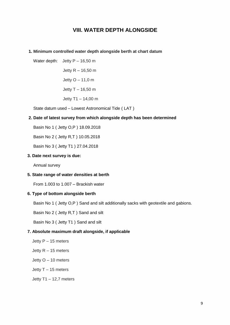
VIII. WATER DEPTH ALONGSIDE
1. Minimum controlled water depth alongside berth at chart datum
Water depth: Jetty P – 16,50 m
Jetty R – 16,50 m
Jetty O – 11,0 m
Jetty T – 16,50 m
Jetty T1 – 14,00 m
State datum used – Lowest Astronomical Tide ( LAT )
2. Date of latest survey from which alongside depth has been determined
Basin No 1 ( Jetty O,P ) 18.09.2018
Basin No 2 ( Jetty R,T ) 10.05.2018
Basin No 3 ( Jetty T1 ) 27.04.2018
3. Date next survey is due:
Annual survey
5. State range of water densities at berth
From 1.003 to 1.007 – Brackish water
6. Type of bottom alongside berth
Basin No 1 ( Jetty O,P ) Sand and silt additionally sacks with geotextile and gabions.
Basin No 2 ( Jetty R,T ) Sand and silt
Basin No 3 ( Jetty T1 ) Sand and silt
7. Absolute maximum draft alongside, if applicable
Jetty P – 15 meters
Jetty R – 15 meters
Jetty O – 10 meters
Jetty T – 15 meters
Jetty T1 – 12,7 meters
10
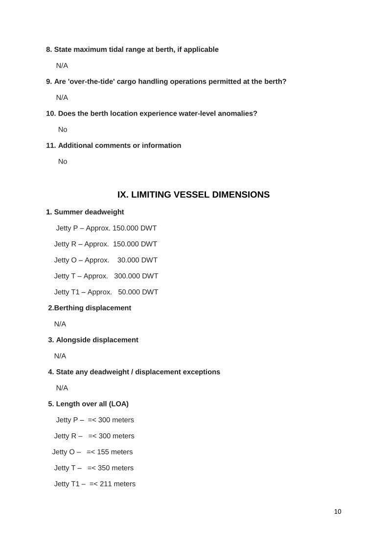
8. State maximum tidal range at berth, if applicable
N/A
9. Are 'over-the-tide' cargo handling operations permitted at the berth?
N/A
10. Does the berth location experience water-level anomalies?
No
11. Additional comments or information
No
IX. LIMITING VESSEL DIMENSIONS
1. Summer deadweight
Jetty P – Approx. 150.000 DWT
Jetty R – Approx. 150.000 DWT
Jetty O – Approx. 30.000 DWT
Jetty T – Approx. 300.000 DWT
Jetty T1 – Approx. 50.000 DWT
2.Berthing displacement
N/A
3. Alongside displacement
N/A
4. State any deadweight / displacement exceptions
N/A
5. Length over all (LOA)
Jetty P – =< 300 meters
Jetty R – =< 300 meters
Jetty O – =< 155 meters
Jetty T – =< 350 meters
Jetty T1 – =< 211 meters

11
6. Beam
No limits
7. Minimum parallel body length (PBL)
Jetty P – 59 meters
Jetty R – 57 meters
Jetty O – no limits
Jetty T – 43 meters
Jetty T1 – 40 meters
8. Freeboard
Freeboard plus ships rails cannot exceed parameters below:
9. Manifold to shipside rail distance
Accordingly to OCIMF Recommendations for Oil and Chemical Tanker Manifolds and
Associated Equipment.
10. Height of manifold above deck or drip tray
Accordingly to OCIMF Recommendations for Oil and Chemical Tanker Manifolds and
Associated Equipment.
11. Manifold spacing
Accordingly to OCIMF Recommendations for Oil and Chemical Tanker Manifolds and
Associated Equipment.
12. Maximum air draft alongside
No restrictions
Jetty P Crude Oil 1,2 m – 20,2 m
Jetty P Heavy Fuel Oil, Diesel, Gasoline, Reformate, Jet Fuel 1,2 m – 18 m
Jetty R Crude Oil, Heavy Fuel Oil, Diesel, Jet Fuel 2,4 m – 22 m
Jetty O Crude Oil, Heavy Fuel Oil 1,2 m – 10,8 m
Jetty O Diesel, Gasoline, Reformate, Jet Fuel 1,2 m – 12,0 m
Jetty T Crude Oil 2,5 m – 23,2 m
Jetty T Naphtha 2,0 m – 16,0 m
Jetty T1 Diesel, Naphtha 1,2 m – 16,0 m
12
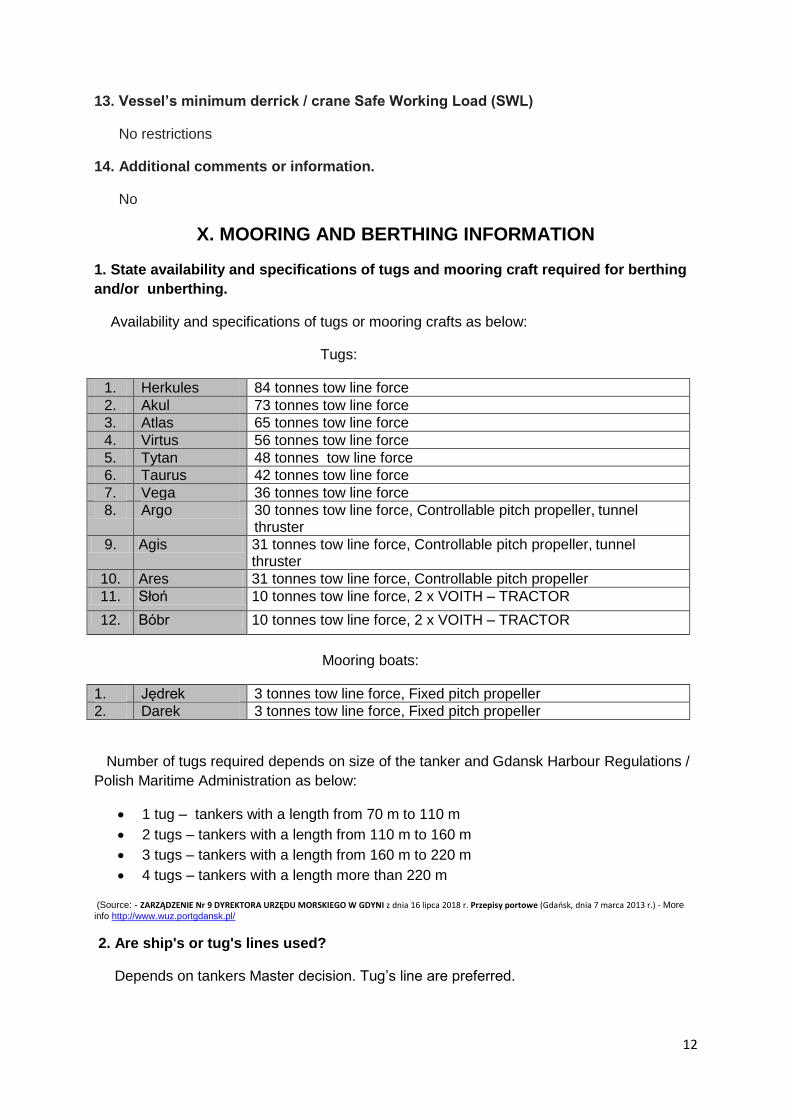
13. Vessel’s minimum derrick / crane Safe Working Load (SWL)
No restrictions
14. Additional comments or information.
No
X. MOORING AND BERTHING INFORMATION
1. State availability and specifications of tugs and mooring craft required for berthing
and/or unberthing.
Availability and specifications of tugs or mooring crafts as below:
Tugs:
1. Herkules 84 tonnes tow line force
2. Akul 73 tonnes tow line force
3. Atlas 65 tonnes tow line force
4. Virtus 56 tonnes tow line force
5. Tytan 48 tonnes tow line force
6. Taurus 42 tonnes tow line force
7. Vega 36 tonnes tow line force
8. Argo 30 tonnes tow line force, Controllable pitch propeller, tunnel thruster
9. Agis 31 tonnes tow line force, Controllable pitch propeller, tunnel thruster
10. Ares 31 tonnes tow line force, Controllable pitch propeller
11. Słoń 10 tonnes tow line force, 2 x VOITH – TRACTOR
12. Bóbr 10 tonnes tow line force, 2 x VOITH – TRACTOR
Mooring boats:
1. Jędrek 3 tonnes tow line force, Fixed pitch propeller
2. Darek 3 tonnes tow line force, Fixed pitch propeller
Number of tugs required depends on size of the tanker and Gdansk Harbour Regulations /
Polish Maritime Administration as below:
1 tug – tankers with a length from 70 m to 110 m
2 tugs – tankers with a length from 110 m to 160 m
3 tugs – tankers with a length from 160 m to 220 m
4 tugs – tankers with a length more than 220 m
(Source: - ZARZĄDZENIE Nr 9 DYREKTORA URZĘDU MORSKIEGO W GDYNI z dnia 16 lipca 2018 r. Przepisy portowe (Gdańsk, dnia 7 marca 2013 r.) - More
info http://www.wuz.portgdansk.pl/
2. Are ship's or tug's lines used?
Depends on tankers Master decision. Tug’s line are preferred.

13
3.Type of fenders installed at berth
Jetty P – Mooring dolphins cell type
Jetty R – Mooring dolphins cell type
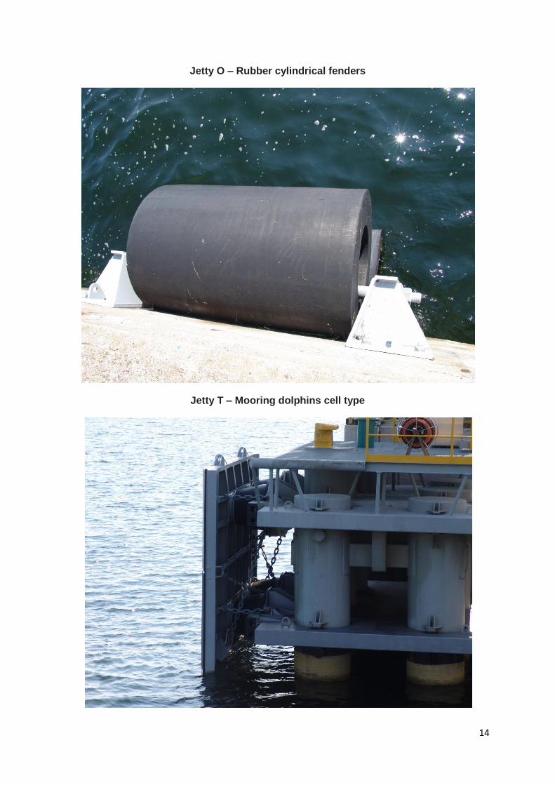
14
Jetty O – Rubber cylindrical fenders
Jetty T – Mooring dolphins cell type

15
Jetty T1 – Mooring dolphins cell type
4. State orientation of vessel alongside berth
Jetty P Starboard side 121o (tanker placed bow to Harbour Exit)
Jetty R Port side 121o (tanker placed bow to Harbour Exit)
Jetty O Starboard side 040o / Port side 220o (preferred port side )
Jetty T Starboard side 121o (tanker placed bow to Harbour Exit)
Jetty T1 Port side 121o (tanker placed bow to Harbour Exit)
5. At buoy moorings, state which side hose is normally connected
N/A
6. Minimum mooring arrangement
Ships smaller than 25.000 DWT – 8 lines including 2 springs
Ships from 25.000 DWT to 50000 DWT – 12 lines including 4 springs
Ships above 50.000 DWT – 16 lines including 4 springs

16
7. Describe any additional mooring requirements
- tanker is obliged to possess additional mooring ropes in case of weather deterioration
when alongside. In case of heavy weather conditions forecast, vessel may be asked
for port’s departure,
- when maximum strength parameters for mooring ropes or mooring equipment are
achieved, the following options should be considered: to attach additional mooring
ropes, to call tugs on ship owner’s account and if possible to take additional ballast,
- terminal suspends cargo operations and disconnect loading arms if mooring
arrangement is not safe,
- mooring alongside the tanker is possible on Harbour Master and terminal permission.
Mooring alongside tanker during loading/discharging, bunkering, ballasting,
deballasting, ventilating or tank to tank pumping is forbidden for all vessels.
- ships equipped with automatic rope supervision must not use the winches in auto
mode. Shifting ship along the Pier using lines is allowed only when permission is
granted by Harbour Master. Tanker is obliged to control lines and mooring equipment
constantly.
8. Are there any restrictions using wire mooring ropes?
If the tanker uses steel wires these must be fitted with non-sparking wire socket.
9. Are there any restrictions using synthetic mooring ropes?
Mooring lines used on tankers should be made of the same material and be spliced in the
same way. Do not use very elastic lines as they may allow excessive movements with the
wind. Do not use lines with different flexibility leading in the same direction.
10. Are there any restrictions on using high modulus synthetic mooring ropes?
Do not use very elastic lines as they may allow excessive movements in strong wind
conditions.
11. Details of any specific mooring equipment required for any vessel utilizing the
berth
No special requirements regarding specific mooring equipment.
12. Does the terminal require the vessel to rig Emergency Towing Off Pennants
(ETOPs) while at the berth?
Yes,
Emergency towing wires should be attached at bow and stern quarter of the tanker. They
have to be supplied with a shackle or a loop 1 -2 meters above the water level and
illuminated at night. The tanker is obliged to control distance from waterline of emergency
towing wires constantly.
17
13. Details of any shore-provided mooring equipment
Mooring boats, messenger lines, bollards/hooks, capstan / mooring winches (see page
34,35)
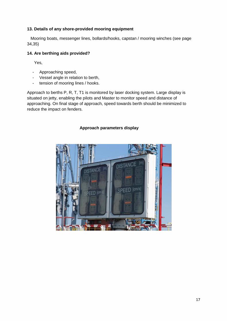
14. Are berthing aids provided?
Yes,
- Approaching speed,
- Vessel angle in relation to berth,
- tension of mooring lines / hooks.
Approach to berths P, R, T, T1 is monitored by laser docking system. Large display is
situated on jetty, enabling the pilots and Master to monitor speed and distance of
approaching. On final stage of approach, speed towards berth should be minimized to
reduce the impact on fenders.
Approach parameters display

18
Chief’s supervisor docking system monitor
15. State allowable speed of approach if applicable
Approach: 4 knots
Berthing : Vessel > 100.000 DWT : 9 cm/s ( pre alarm 7 cm/s )
Vessel < 100.000 DWT: 11 cm/s ( pre alarm 9 cm/s )
16. Is a mooring tension monitor fitted?
Yes, on mooring hooks of jetties P, R, T, T1
17. Are mooring hook quick release arrangements provided?
Yes, on T1 jetty - automatic system,
P,R,T jetties – manual system
18. Anchor chain stopper requirements
Yes, chain stoppers has to be locked and secured on chain.
19. Largest ship handled at berth to date
By DWT : m/t Atlantas 321.300 DWT (LOA 333 m), IMO NR – 9389899,
25.08.2016 – jetty T
By LOA : m/t Universal Hope, 343,7 m ( DWT 299.700 ) , IMO NR – 9002611,
03.04.2006 – jetty T

19
20. Additional comments or information
Mooring gang has to be ordered vis Ship’s and Agent.
XI. BERTH EQUIPMENT AND FACILITIES
1. Number, type and size of cargo transfer connections
Jetty P – Cargo arm no 1 : 16’’ Crude oil, QCDC coupling
Cargo arm no 2 : 16” Crude oil, QCDC coupling
Cargo arm no 3 : 16’’ Crude oil, QCDC coupling
Cargo arm no 4 : 16’’ Crude oil, QCDC coupling
Cargo arm no 5 : 12’’ Crude oil, Heavy fuel oil, QCDC coupling
Cargo arm no 6 : 12’’ Gasoline, Diesel, Jet fuel, QCDC coupling
Cargo arm no 7 : 12’’ Gasoline, Diesel, Jet fuel, QCDC coupling
Jetty R –Cargo arm no 8 : 12’’ Crude oil, Heavy fuel oil,
Cargo arm no 9 : 16’’ Crude oil
Cargo arm no 10 : 16’’ Crude oil
Cargo arm no 11 : 16’’ Crude oil
Cargo arm no 12 : 16’’ Jet fuel, Diesel
Jetty O – Cargo arm no 13 : 8’’ Crude oil, Heavy fuel oil,
Cargo arm no 14 : 10’’ Gasoline, Jet fuel, Diesel , QCDC coupling
Jetty T – Cargo arm no 15 : 16’’ Crude oil,
Cargo arm no 16 : 16’’ Crude oil,
Cargo arm no 17 : 16’’ Crude oil,
Cargo arm no 18 : 16’’ Crude oil,
Cargo arm no 19 : 12’’ Straight Run Naphtha
Jetty T1- Cargo arm no 23 : 12’’ Straight Run Naphtha, Diesel, QCDC coupling
20
2. List grades handled at berth
Gasoline - jetties O, P
Trade name: Unleaded petrol 93, Unleaded petrol 95, Unleaded petrol 95 AL, Unleaded
petrol 95 Export, Unleaded petrol 98
Gasoline (crude oil) – jetties T, T1
Trade name: Straight Run Naphtha
Petroleum oil all reforming fractions – jetties O, P
Trade name: Reformate
Kerosene – jetties O, P, R
Trade name: Aviation fuel Jet A-1, Aviation fuel F34, Aviation fuel F-35
Heavy fuel oil, Residual fuel oil – jetties O, P, R
Trade name: Fuel oil RG 1, Fuel oil RG 1
Diesel – jetties O, P, R, T1
Trade name: Diesel fuel, Diesel Fuel Automotive
Crude oil – jetties O, P, R, T
3. State transfer rate restrictions and back pressure for each cargo grade
Crude Oil 1000-10000m3/h ( 250-1000m3/h Jetty O )
Heavy Fuel Oil 300-1000m3/h
Gasoline 250-2500m3/h
Diesel 250-2200m3/h
Straight Run Naphtha 250-2500m3/h
Jet Fuel 250-1000m3/h
Reformate 250-2500m3/h
Design pressure range for all cargos is 0 – 10 Bars
4. Are transfer connections fitted with insulation flanges?
Yes,
Fixed insulation flange on the loading arms (resistance 10 thousand Ω – ohm)

21
5. State storage type for LPG
N/A
6. Describe any terminal-specific requirements for vessel manifolds
Vessel manifolds arrangement has to comply with latest OCIMF publication
“Recommendations for Oil Tanker Manifolds and Associated Equipment”
7. Is berth fitted with a vapour manifold connection?
Yes,
Jetty O : 6” Gasoline ( hose )
Jetty P : 12” Gasoline ( arm ), 16” Crude Oil ( arm )
Jetty R : 12” Crude Oil ( arm )
Jetty T : 8” Gasoline ( hose),16” Crude Oil ( arm )
Jetty T1 : 8” Gasoline ( hose )
8. State throughput rate(s) of vapour recovery system
Allowable cargo transfer rate of VRS installation is 1500 – 10000 m3/h. Highest volume of
cargo handling rate for vapour receipt is 11.000 m3/h.
9. Are Powered Emergency Release Couplings (PERCS) installed to the cargo transfer
arms?
Yes, fixed on all loading arms
10. Does the berth have an emergency shutdown (ESD) capability that can be
activated by the ship?
No
11. Describe access arrangements between ship and shore.
Jetty O – ship’s gangway
Jetty P – shore/ship’s gangway – depends on vessel size
Jetty R – shore/ship’s gangway – depends on vessel size
Jetty T – shore/ship’s gangway – depends on vessel size
Jetty T1 – ship’s gangway
“P”, “R” and “T” berths are supplied with shore gangways to provide ship-shore access.
In case of insufficient space on deck for the gangway or uneasy access, Tanker is obliged to
rig an accommodation ladder or gangway.

22
The means of access to the ship should be safe and may consist of an appropriate gangway
or accommodation ladder with a properly secured safety net fitted to it. A lifebuoy should be
available on board the ship near the gangway or accommodation ladder.
The access should be safely and properly illuminated during darkness. On arrival to the
terminal, tanker should display notices at the gangway in English language stating:
Vessel should display on gangway below meanings:
„WARNING”
„NO NAKED LIGHTS”
„NO USE OF MOBILE PHONES”
„NO SMOKING ”
„NO UNAUTHORISED PERSONS”
„EMERGENCY ESCAPE ROUTES”
The ship’s staff should control access to the tanker in cooperation with terminal. The
controlling personnel should maintain effective deck watch around the tanker.
12. Does the berth have pollution response equipment?
Yes,

23
Anti pollution kits (all jetties)
Oil absorbent powder

24
Absorbent oil booms
Portable anti-spill pumps

25
Skimmer
Oil spill vessel

26
Permanent anti-spill barriers around the terminal
Permanent anti-spill barriers inside the terminal between jetties P and R
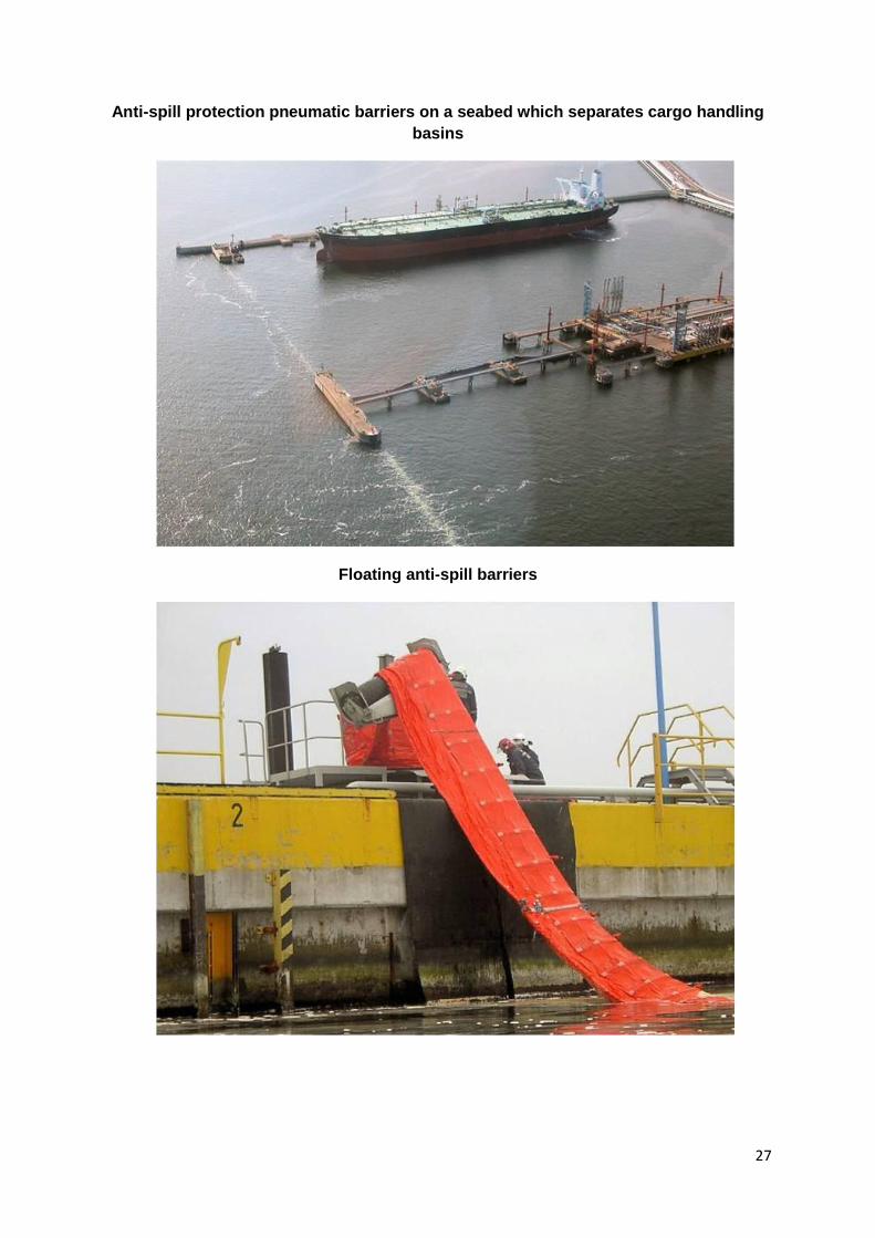
27
Anti-spill protection pneumatic barriers on a seabed which separates cargo handling
basins
Floating anti-spill barriers
28
XII. BERTH OPERATIONS
1. What is the primary and backup communication system between ship and terminal
during cargo operations?
- Loading Supervisor on board
- Primary VHF Ch. 20, 22
- Back up VHF Ch. 68, 9
- Jetty Operator (telephone in Operator’s cabin)
2. Is it required that terminal or shore representatives stay on board during
operations?
Yes, 1 person on vital stages of operations and when required i.e.: - cargo
commencement / completion, line displacement, COW, repetitive checks at intervals not
exceeding 4 hours etc.
3. Specify weather/environmental restrictions for stopping cargo operations,
disconnecting hoses or arms and vacating the berth?
Cargo operations should be suspended and loading arms should be disconnected when
one of the situations occur: wind force 9 in Beaufort Scale, problems with proper berthing of
tanker or when the tanker's movement alongside the quay approaches the limit of loading
arms' deflection. Cargo operations are stopped also in the case of thunderstorm - (see
Terminal Regulations & Information booklet)
Vessel should be ready to cast off when weather deterioration make moorings unable to hold
vessel in position. Vessel should take into account Harbour Master instructions. Tugs may be
called for assistance if necessary as evaluated by the vessel.
4. Are there any restrictions regarding tank cleaning/Crude Oil Washing (COW)
operations at berth?
Yes,
Tank washing and gas freeing except crude oil washing (COW) alongside the cargo
handling Berths of the Terminal are prohibited.
Crude Oil Washing may be performed following the requirements from Terminal Regulations
& Information booklet, Chapter 11 – COW operation. It is strictly forbidden to heat crude oil
for cargo tank washing.
Crude Oil Washing (COW) is a MARPOL’S requirement for all Crude Oil carriers. Minimum
of 25% of the total number of tanks, in addition to the Heavy weather ballast tanks, needs to
be washed, every voyage for sludge control, provided that all vessels tanks are washed in a
quarterly period.

29
5. Are there any berth specific requirements regarding tanker inerting procedures?
Yes,
Tankers obliged by SOLAS Convention to be in possession of the inert gas system are to
maintain it ready to use. Before and during loading all tanks must be inerted. If there is a
failure of the system during discharging,
the operation must be stopped immediately and Terminal informed. Only after eliminating the
failure, the cargo handling operation can be resumed.
The oxygen content in the cargo tanks should be at the level not higher than 8%.
6. Is there a temperature limit for cargo handled?
Yes,
Crude Oil + 35 oC Jetty T, R
Crude Oil + 30 oC Jetty O, P
Gasoline + 30 oC
Diesel Oil + 30 oC
Heavy Fuel Oil + 80 oC
Reformate + 30 oC
Jet fuel + 30 oC
Naphtha + 30 oC
7. Is it permitted for vessels to undertake double-banked operations alongside the
berth?
NO
8. Is vessel required to pump water ashore or receive water on board for line clearance
purposes?
NO
9. Can the berth be used for Ship-to-Ship transfers using terminal facilities?
NO
10. State details regarding any environmental / firefighting restrictions applicable at
the berth
- Fire-fighting equipment on board should be correctly positioned and ready for immediate
use. The ship fire main systems should be pressurized or be capable of being
pressurized at short notice. Fire hoses should be uncoiled and connected to the main
line; at least two should be placed near the manifold, one forward and one aft of it. At
least two (12 kg each) portable dry powder extinguisher should be placed conveniently

30
for use near manifold.
Fixed monitors should be ready and, if remotely activated or manually, adjusted to protect
the manifold area before operations begin. A fire plan should be available on board the
ship near the gangway or accommodation ladder.
- All vessel’s cargo and bunker pipelines has to be properly secured with blank flanges
fully bolted.
- Drip trays should be put under Tanker's manifolds connected with cargo arms if the
Tanker is not supplied with structural drip trays.
- Scuppers should be tightly closed. Any spill on deck must be cleaned immediately and
oily wastes have to be kept in tight containers.
- In Naftoport Oil Terminal only closed ullaging and sampling systems are allowed.
- While loading/discharging all cargo tank lids must be closed..
- Disposal of garbage or any objects overboard is forbidden. Discharge of oil,
oil mixtures or chemicals into the harbour waters is strictly prohibited.
- Excessive smoking and funnel sparking from Tanker funnels must be immediately
ceased.
- Discharge of clean segregated ballast directly into the harbour waters requires a prior
declaration by Master or Chief Officer. Accordingly to Terminal Regulations & Information
Chapter 13 Gdansk Harbour Master (VHF Ch.14), and the Loading Supervisor’s
notification. Approval is required to discharge ballast tanks.
- Gas freeing alongside in Naftoport Oil Terminal is prohibited.
- All activities which may potentially cause of spark or smoke are strictly forbidden during
port stay.
- Upon completion of cargo operation, all loading arms will be drained before
disconnected.
11. Are there any restrictions regarding Hydrogen Sulphide content in Cargo Tanks?
No restriction regarding H2S level in cargo tanks, however the Terminal has its own
regulations regarding H2S - see www.naftoport.pl TAB: Terminal / Terminal Code of
Practice.
12. Are there any restrictions regarding Mercaptan content in Cargo Tanks?
No,
13. Are there any restrictions on handling stores when a ship is moored alongside
berth?
Yes,
- All necessary info regarding stores can be found in Terminal Code of Practice
http://naftoport.pl TAB: Terminal/Terminal Code of Practice.
- It is prohibited to use provision crane or davit when cargo arm/ arms are connected.

31
XIII. AVAILABLE SERVICES
1. Are Heavy Fuel Oil bunkers available?
Yes, High Sulphur Fuel Oil
Berths - P,R,T,T1 - bunker barge
Berth - O - bunker barge or tank truck ( tank truck temporarily suspended )
2. Are Diesel Oil bunkers available?
Yes, Low Sulphur Marine Gasoil
Berths - P,R,T,T1 - bunker barge
Berth – O - bunker barge or tank truck ( tank truck temporarily suspended )
3. Are Intermediate Oil bunkers available?
Yes,
Berths - P,R,T,T1 bunker barge
Berth - O bunker barge or tank truck ( tank truck temporarily suspended )
4. Is fresh water available?
Yes, but not for all berths,
Berths - P, R, O – available
Berths - T,T1 - not available
5. Are slop reception facilities available?
Yes,
Berths - P,R,T,T1 service barge
Berth - O service barge or tank truck ( tank truck temporarily suspended )
6. Are dirty ballast reception facilities available?
Yes,
Berths - P,R,T,T1 service barge
Berth - O service barge or tank truck ( tank truck temporarily suspended )
7. Are engine room sludge and bilge reception facilities available?
Yes,

32
Berths - P,R,T,T1 service barge
Berth - O service barge or tank truck ( tank truck temporarily suspended )
8. Are garbage reception facilities available at the berth.
Yes,
Berths - P,R,T,T1,O truck
9. Additional comments or information
Bunkering, slop, dirty ballast, engine room sludge and bilge reception, and garbage reception
operations to be arranged by Tanker’s Agent.
Fuel supply from the bunker barge/tank truck, slop, dirty ballast, sludge or bilge disposal
can be carried out only before commencement or after completion of cargo operations and
requires prior consent of Harbour Master.
During bunkering of the tanker, all fire safety rules should be applied. Bunkering should be
carried out under constant supervision by the ship’s officer. More information concerning the
organization and supply bunker from tank truck on berth “O” can be found on the website
www.naftoport.pl TAB: Terminal / Terminal Code of Practice.
Waste declaration must be completed and submitted prior to arrival. However the vessel has
to deposit garbage into correct, dedicated bins / containers.
XIV. BERTH LOW TEMPERATURE IMPACT
1. What is the typical range of temperatures the terminal operates in during a winter
season?
Avg temperature: + 5,9 oC (February 2009), - 9 oC (January 1987)
Min. temperature: - 23 oC (January 1987)
Max. temperature: + 17,6 oC (February 2009)
2. Which months of the year can ice be expected?
January, February ( only inside cargo handling basins, do not affects navigation)
3. Specify any terminal requirements for vessel Ice Class notation and winterisation
Capabilities.
N/A

33
4. State the minimum temperature of cargoes handled.
Mean minimum cargo temperature during winter is approx. -2oC - -3oC
Minimum allowed temperature of cargoes -16oC ( Except HFO )
5. Does the terminal have its own resources for conducting icebreaker escort
N/A
6. Are there icebreakers available to operate in the terminal area
Yes, in the event of ice in basins, relevant tugs deputize, see below
7. Does the terminal have ice-capable tugs and support craft
Yes,
Tug Vega IMO 9375343
GRT 144 t / Power 2 x 1050kW / Ice class (PRS) Lm1
Tug Argo IMO 8102593
GRT 331 t / Power 1840kW / Ice class (PRS) L1
Tug Agis IMO 8102581
GRT 330 t / Power 1840kW / Ice class (PRS) L1
Maximum ice thickness 25 cm
More info visit http://wuz.portgdansk.pl/
8. Does the terminal have specific requirements for the vessel speed and
maneuverability characteristics in ice?
No
9. Does the terminal provide its own ice navigator/advisor?
No, pilot only
10. Additional comments or information
No

34
XV. SUPPLEMENTARY INFORMATION
1. Berth transparently
Jetty P Concrete structure ( loading platform, dolphin system)
Jetty R Concrete structure ( loading platform, dolphin system )
Jetty O Pier
Jetty T Concrete structure ( loading platform, dolphin system )
Jetty T1 Concrete structure ( loading platform, dolphin system )
2. Preferred berthing orientation for vessels alongside
Jetty P Starboard side ( tanker placed bow to Harbour Exit)
Jetty R Port side ( tanker placed bow to Harbour Exit)
Jetty O Starboard side / Port side ( preferred port side )
Jetty T Starboard side ( tanker placed bow to Harbour Exit)
Jetty T1 Port side ( tanker placed bow to Harbour Exit)
3. Specify datum used for height and depth measurements in this section
Lowest Astronomical Tide ( LAT )
4. Berth height above datum
Jetty P – approx. 5.10 m
Jetty R – approx. 5,10 m
Jetty O – approx. 2,20 m
Jetty T – approx. 5,10
Jetty T1 – approx. 3,0 m, mooring points 4,30 m
5. Berth heading
Jetty P – 121o
Jetty R – 121o
Jetty O – port side 040o, starboard side 220o
Jetty T – 121o
Jetty T1 – 121o

35
6. Minimum controlled water depth alongside berth
Jetty P – 16,50m
Jetty R – 16,50 m
Jetty O – 11,0 m
Jetty T – 16,50 m
Jetty T1 – 14,00 m
7. Width of the channel adjacent to the berth
Basin no 1 – approx.250 m – distance between mooring dolphins line Jetty P and
breakwater
Basin no 2 – approx. 255 m – distance between mooring dolphins line Jetty R and
Jetty T
Basin no 3 – approx. 140 m - distance between mooring dolphins line Jetty T1 and
permanent anti-spill barriers
8. Position of mooring bollards and hooks
See diagram, point 12 - Additional comments or information / pages 37 and 38 this TPQ
9. Position of mooring buoys
N/A

36
10. Fender Location
See diagram, point 14 - Additional comments or information.

37

38
![EfficientTreePatternQueriesOnEncrypted XML Documents · 2015. 4. 27. · In this paper we consider tree pattern query (TPQ) [8, 28] over encrypted XML docu-ments. A TPQ is a tree,](https://static.fdocuments.us/doc/165x107/607f9c0f7053b5278f18a38a/eficienttreepatternqueriesonencrypted-xml-2015-4-27-in-this-paper-we-consider.jpg)


![On Trip Planning Queries in Spatial Databases - cs.bu.edu · be reduced to an instance of TPQ. TPQ is also closely related to the group minimum spanning/steiner tree problems [24,20,16],](https://static.fdocuments.us/doc/165x107/5d4f5fa688c9936e718bbb0d/on-trip-planning-queries-in-spatial-databases-csbu-be-reduced-to-an-instance.jpg)