Data structures and algorithms CSE - 246 fall 2010 – bs -III term project - monopoly
Upload
burak-sunanCategory
view
219download
0
8/6/2019 Term Project III
http://slidepdf.com/reader/full/term-project-iii 1/6
8/6/2019 Term Project III
http://slidepdf.com/reader/full/term-project-iii 2/6
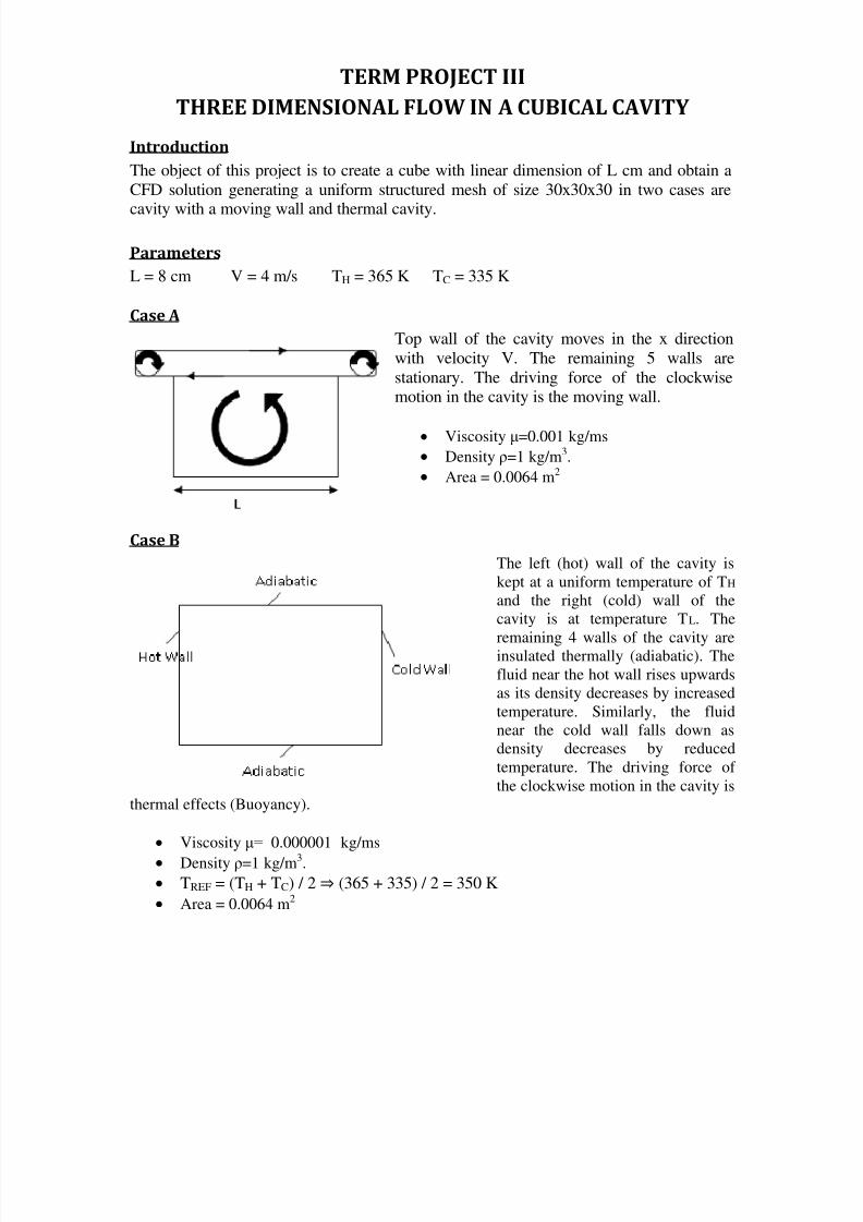
TERM PROJECT III
THREE DIMENSIONAL FLOW IN A CUBICAL CAVITY
Introduction
The object of this project is to create a cube with linear dimension of L cm and obtain a
CFD solution generating a uniform structured mesh of size 30x30x30 in two cases are
cavity with a moving wall and thermal cavity.
Parameters
L = 8 cm V = 4 m/s TH = 365 K TC = 335 K
Case A
Top wall of the cavity moves in the x direction
with velocity V. The remaining 5 walls are
stationary. The driving force of the clockwisemotion in the cavity is the moving wall.
Viscosity μ=0.001 kg/ms
Density ρ=1 kg/m3.
Area = 0.0064 m2
Case B
The left (hot) wall of the cavity is
kept at a uniform temperature of TH
and the right (cold) wall of the
cavity is at temperature TL. The
remaining 4 walls of the cavity areinsulated thermally (adiabatic). The
fluid near the hot wall rises upwards
as its density decreases by increased
temperature. Similarly, the fluid
near the cold wall falls down as
density decreases by reduced
temperature. The driving force of
the clockwise motion in the cavity is
thermal effects (Buoyancy).
Viscosity μ= 0.000001 kg/ms
Density ρ=1 kg/m3.
TREF = (TH + TC) / 2 ⇒ (365 + 335) / 2 = 350 K
Area = 0.0064 m2

8/6/2019 Term Project III
http://slidepdf.com/reader/full/term-project-iii 3/6
Figure 1. Case A_Scaled Residuals
Figure 2. Drag History
Figure 3. Case A_Ux

8/6/2019 Term Project III
http://slidepdf.com/reader/full/term-project-iii 4/6
Figure 4. Case A_Uy
Figure 5. Case B_Scaled Residuals
Figure 6. Case B_Heat Flux on Wall Left

8/6/2019 Term Project III
http://slidepdf.com/reader/full/term-project-iii 5/6
Figure 7. Case B_Heat Flux on Wall Right
Figure 8. Case B_Static Temperature
Figure 9. Case B_Ux

8/6/2019 Term Project III
http://slidepdf.com/reader/full/term-project-iii 6/6
Figure 10. Case B_Uy
Calculations
Case A
() ⇒
where V is velocity, L is length, ρ is density and μ is dynamic viscosity. Re is equals to320 smaller than critical value 5000, and therefore the flow is laminar.
Case B
() ( )
()
⇒
⁄
where g is gravitational acceleration, β=1/ TREF and TREF is the reference temperature. Gris equals to 430518857 smaller than critical value 10
9and therefore the flow is laminar.