TeraSci Power Supply Operators Manual
33
5362 Production Dr. Huntington Beach, CA 92649 714-896-0150 Web Site: www.terasci.com Email: [email protected] TeraSci Power Supply Operators Manual Page 1 of 33 TeraSci Power Supply Operators Manual Al Donnelly
Transcript of TeraSci Power Supply Operators Manual

5362 Production Dr. Huntington Beach, CA 92649 714-896-0150 Web Site: www.terasci.com Email: [email protected]
TeraSci Power Supply Operators Manual Page 1 of 33
TeraSci Power Supply Operators Manual Al Donnelly

5362 Production Dr. Huntington Beach, CA 92649 714-896-0150 Web Site: www.terasci.com Email: [email protected]
TeraSci Power Supply Operators Manual Page 2 of 33
Contents
1. Introduction and Key Features: Software and Hardware 2. Tester Operation & Operators Test Steps 3. Test Parameters 4. Spare Parts – Service installation points
Load test boardsMicro Controller
Board
AC relay
Triac AC controller
CPU and internal power supply
PSU Tester – Internal Components

5362 Production Dr. Huntington Beach, CA 92649 714-896-0150 Web Site: www.terasci.com Email: [email protected]
TeraSci Power Supply Operators Manual Page 3 of 33
1. Introduction The TeraSci Power Supply Tester is an extension of our basic testing architecture. The power supply tester is viewed as the data collection platform. It is designed to be operated by non-skilled, low cost test operators. All of the functional test decisions are made by the test software. The test software is designed to monitor the operator performance for throughput and yield. The power supply tester collects dozens of data points relating to the product performance, equipment operation, software revisions, and operator training issues. All of these data points are sent to the Tracker Data Base. The Tracker software then manages the power supply test process by providing real time reports. These reports provide information on yield, operator training issues, test equipment maintenance, and product performance and FA data. One of the key pieces of the TeraSci test architecture is the connection to the Internet. This connect makes it possible to provide remote engineering support. The volume of data collected by the tester and formatted by the Tracker Software permits engineers from many different places to quickly review yield issues and make recommendations. For example TeraSci can access the data to monitor equipment performance and implement software upgrades in real time. The OEM’s can monitor the power supply performance and FA data and make recommendations to change pass fail criteria or test setups. The power supply tester software architecture permits on site production test engineers to quickly modify the test scripts and test setup parameters. This allows the product to be quickly re-tested and the remote engineers to have feedback on changes in a timely fashion. A key part of the TeraSci testing philosophy is that processing field return products is not a static environment. As data is collected and analyzed over a period of time trends will emerge. The ability to spot these trends and to explain or correct the deviations is the strength of a good test system. TeraSci believes it has the tools in place to

5362 Production Dr. Huntington Beach, CA 92649 714-896-0150 Web Site: www.terasci.com Email: [email protected]
TeraSci Power Supply Operators Manual Page 4 of 33
Key Features
Software Features
Microprocessor Based test system o Limited Hard Code sequences increases flexibility o Micro-P Interprets Script and Configuration Files o DSP processing for all ADC measurements and Active Load controls
Script Based test sequences o High failure modes tested first (improves test throughput) o Flexible prompts (wording varies from supply to supply) o Full retry for operator setup errors
System prompts operator when setup failures detected Allows operator to retry instead of logging false failures Informs operator of the exact failure mode
o Outputs error descriptions for fatal errors (to log file) Improves Failure Analysis Monitors trends Operator quality control
o Permits quick and easy test process modifications Supports special test sequences for individual PS's Supports tighter pass/fail criteria for individual PS's
Configuration file for each model tested o Load (current) requirements for each voltage o Pass/Fail limits for each voltage o Number of connectors to be checked o Power Good time limit (if applicable) o Power Fan Control voltage input levels (if required) o Adaptor Module ID control o Custom Operator Prompts o Custom Operator VMI checks
Log File for each supply tested (into SQL Data Base) o Software revision level logged o Operator ID logged o Test unit ID is CT number o Power Good Time o Fan Status o Full connector check o Full Voltage check at multiple load points o Operator Comment line for VMI issues o Status Line for Functional Test results
5362 Production Dr. Huntington Beach, CA 92649 714-896-0150 Web Site: www.terasci.com Email: [email protected]
TeraSci Power Supply Operators Manual Page 5 of 33
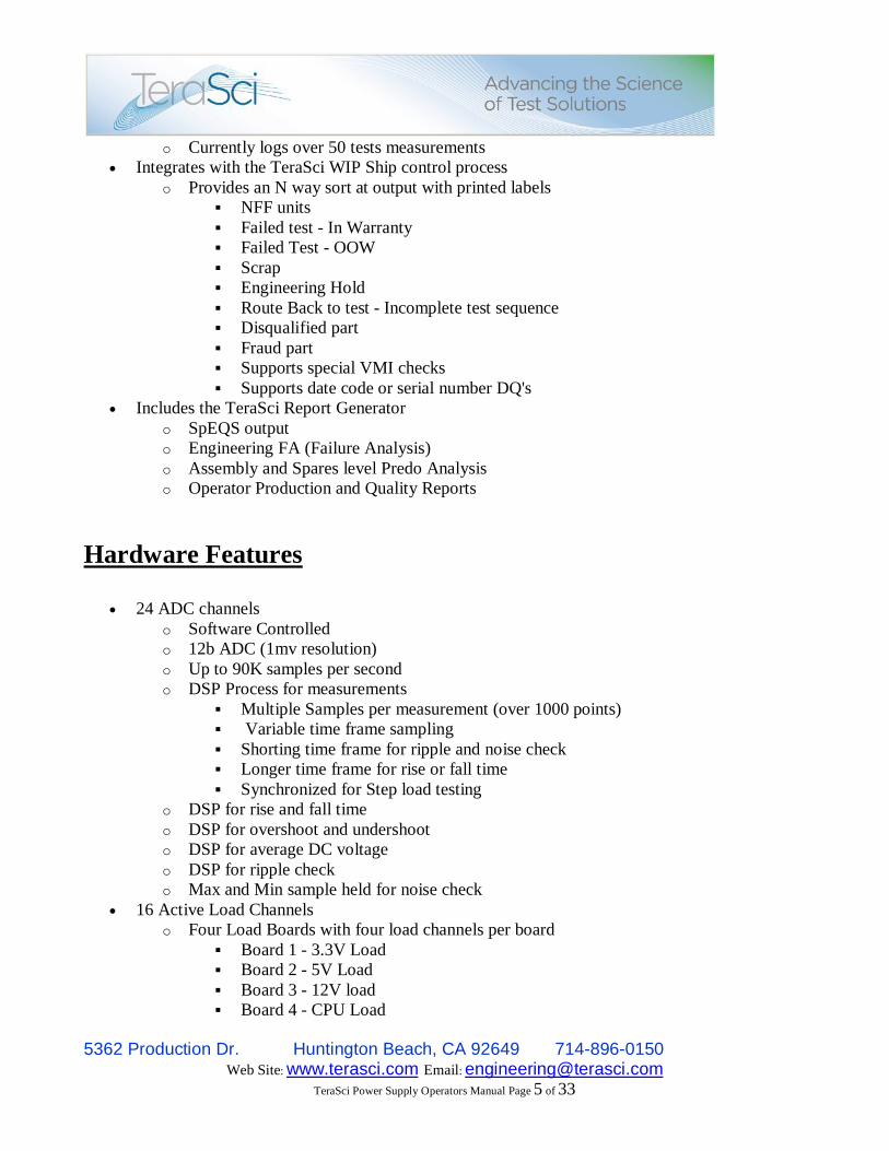
o Currently logs over 50 tests measurements Integrates with the TeraSci WIP Ship control process
o Provides an N way sort at output with printed labels NFF units Failed test - In Warranty Failed Test - OOW Scrap Engineering Hold Route Back to test - Incomplete test sequence Disqualified part Fraud part Supports special VMI checks Supports date code or serial number DQ's
Includes the TeraSci Report Generator o SpEQS output o Engineering FA (Failure Analysis) o Assembly and Spares level Predo Analysis o Operator Production and Quality Reports
Hardware Features
24 ADC channels o Software Controlled o 12b ADC (1mv resolution) o Up to 90K samples per second o DSP Process for measurements
Multiple Samples per measurement (over 1000 points) Variable time frame sampling Shorting time frame for ripple and noise check Longer time frame for rise or fall time Synchronized for Step load testing
o DSP for rise and fall time o DSP for overshoot and undershoot o DSP for average DC voltage o DSP for ripple check o Max and Min sample held for noise check
16 Active Load Channels o Four Load Boards with four load channels per board
Board 1 - 3.3V Load Board 2 - 5V Load Board 3 - 12V load Board 4 - CPU Load

5362 Production Dr. Huntington Beach, CA 92649 714-896-0150 Web Site: www.terasci.com Email: [email protected]
TeraSci Power Supply Operators Manual Page 6 of 33
o Flexible Configuration All load boards are identical circuits All boards have an individual Micro-P All loads on 1 board can be paralleled (increased overall load)
o Micro-P controlled load circuit (DSP) Programmable current control Loads are defined by Configuration file Script file selects appropriate load for required test Script file can select overload Script file can select Short circuit (up to 60A pulse) Script file can select over-voltage injection
o Linear Load (not a PWM or Chopper based load) o Up to 50W per channel
programmable from 1W to 50W Up to 10 amps (per channel) Continuous operation at 50W (per channel)
o Active load boards calculate total power consumption Measures input voltage level Measures (and controls) real time current in load Supports Power supply efficiency test
Low power active load System o 5V Standby Load o 3.3V AUX load o -12V Load o Short Circuit and Overload check for each Voltage o Power Consumption Monitoring for each voltage
Power Fan Control o Script controlled input DC level from 200mv to 3VDC o PS TACH Pin output measurement o Fan Sink voltage Level Check o Fan Air Flow measurement with Vane based Anemometer
AC Line Input Control o Software controlled ON/OFF contactor o Adjustable line voltage control
Low Line capability High Line capability Independent of actual line voltage input
o AC Line voltage measurement (1 ADC channel) o AC Line current measurement (1 ADC channel) o AC power Input measurement
Power supply efficiency test Flexible Power Supply connection Modules
o Separate ATX and AUX connector modules o ATX Modules

5362 Production Dr. Huntington Beach, CA 92649 714-896-0150 Web Site: www.terasci.com Email: [email protected]
TeraSci Power Supply Operators Manual Page 7 of 33
Multiple ATX modules with different configurations Supports various ATX connector configurations Supports CPU, Video, and PCI connector configurations Designed for maximum current loads (supports over 75 amps) Supports Power On - Power Good pins Supports Power Fan Control (for ATX implementation) Supports TACH output (for ATX implementation) Modules have software ID (prompts if wrong module installed)
o AUX Connector Module 8 AUX connectors 6 SATA connectors 2 Floppy connectors Power Fan Control output (for separate PFC connector) Fan Sink voltage input Fan TACH input Anemometer Input Green LED at each connector - prompts setup Red LED at each connector - for connector problems 5V and 12V inputs for each connector are FET switched Each connector tested individually 1 AMP load on each voltage (verifies current capability) SATA 3.3V are checked for each individual connector Removal Tool for AUX connector eliminates pulling on wires
Calibration Software Menu o Permits Ease of System Calibration o Flash Based Correction Tables
IR drop adjustment from connector pin to test point Intended for high load current variations

5362 Production Dr. Huntington Beach, CA 92649 714-896-0150 Web Site: www.terasci.com Email: [email protected]
TeraSci Power Supply Operators Manual Page 8 of 33
2. Tester Operation
The power supply test platform is designed to be a very low cost high volume test system. The operator responsibility is to select the proper power supply adaptor and connect the power supply to the tester. Power supplies vary in the number and type of power connectors. The TeraSci tester has pluggable power supply adaptor boards that accommodate these different configurations. The adaptor boards also provide the fixed loads for the power supply bias supplies such as -5V, -12V, and Standby 5V. The adaptor boards have jumper settings to identify which board is connected to the system. If the operator connects the wrong adaptor board the software will inform the operator to change adaptors.

5362 Production Dr. Huntington Beach, CA 92649 714-896-0150 Web Site: www.terasci.com Email: [email protected]
TeraSci Power Supply Operators Manual Page 9 of 33
The operator starts the test software by pressing “T” and then <Enter>, then logging in and pressing the <F1> function key. The software prompts the operator to enter the power supply identification. The identification is the CT number or the assembly number of the power supply. The software performs a lookup of the CT (using the 4 digit assembly code) or the assembly number in the power supply MODELS.CSV. If the CT or assembly number is not present the operator is notified that this power supply is not supported. The test engineer must add support for this assembly. Section 4 of this document describes the process to add new assemblies to the test system. Once the assembly number has been found in the MODELS.CSV the software finds the corresponding CONFIG.CSV file. Each power supply will have its own unique CONFIG file. Within the CONFIG file are the adaptor number, the SCRIPT file name, the test load parameters, and the pass fail criteria. The software transfers the CONFIG and SCRIPT files to the test port and starts the power supply test. Within each test port window is an operator prompt line. If the test software requires an operator action the operator prompt line will display a red message. The operator must acknowledge the red messages by performing the required action and pressing the appropriate function key. The test software will also provide progress messages in green on the operator prompt line. When the test has competed the operator prompt line will display: “Test Complete Log out the supply” The operator should press F8 to log out the drive. This will create a TRK (the file containing the test results) and send it to the Tracker Data Base.

5362 Production Dr. Huntington Beach, CA 92649 714-896-0150 Web Site: www.terasci.com Email: [email protected]
TeraSci Power Supply Operators Manual Page 10 of 33
Operators Test Steps
Preface:
This document is designed to provide instructions on how to run the TeraSci Power Supply Test, basic troubleshooting, code updates and requesting a new profile. If any issues arise that are not covered in this document, please contact TeraSci Engineering Support ([email protected]).
Section Guide:
1.) Running the Power Supply Test 2.) Troubleshooting the Power Supply Tester 3.) Updating Code on the Power Supply Tester 4.) Requesting new Profiles

5362 Production Dr. Huntington Beach, CA 92649 714-896-0150 Web Site: www.terasci.com Email: [email protected]
TeraSci Power Supply Operators Manual Page 11 of 33
Section 1.0 – Running the Power Supply Test
1. Power up the tester and ensure the emergency stop button is depressed.
NOTE: In the event of an emergency, quickly press the emergency stop button to kill the power to the unit under test. 2. Start the test by typing “T” at the Linux command prompt: 3. Next login using your username and password:
NOTE: Usernames are maintained by the site’s local Engineering group.
This button will power up the test station.
This is the emergency stop button. Ensure it is depressed or the tester will not provide power to the unit under test.

5362 Production Dr. Huntington Beach, CA 92649 714-896-0150 Web Site: www.terasci.com Email: [email protected]
TeraSci Power Supply Operators Manual Page 12 of 33
4. Press <F1> to start the test: 5. Enter the CT Number of the Power Supply:
NOTE: If the supply does not have a CT Number, then press enter to by-pass this and then enter the supply’s part number.
6. Next plug in the connections as prompted by the test, the tester will light up the LED’s next to the connectors that are required to be plugged in, only plug in the connections that have an LED light next to them. If the board requires a different ATX Combo board, the test will prompt to install this board (hot swappable) before prompting to plug in any
connections: 7. After the connections have been established, press the <F1> key to continue the test. The
test will then check several parameters:

5362 Production Dr. Huntington Beach, CA 92649 714-896-0150 Web Site: www.terasci.com Email: [email protected]
TeraSci Power Supply Operators Manual Page 13 of 33
8. If the test passes the initial checks it will prompt to install the Auxiliary (AUX), SATA and Floppy (FLP) connections. NOTE: If any of these ports go bad, you can use any of the other ports, and the test will automatically detect this and use that port. If a port should go bad, please mark it and cover it with a sticker so that no one will attempt to use it.
9. Once the test is complete it will prompt the operator to logout the supply.
10. Press the <F8> key to log out the supply. The test will then prompt the operator to pick a
comment; this is where the operator can manually fail a unit for visual damage or audible failure (i.e. noisy fan). In most cases the #1 option for Pass Visual Exam will be used, as most visual damage should be screened out prior to the part coming to the test area.
11. The test will then prompt the operator to press “A” to accept or “R” to reject. This option is
here in case the wrong comment was picked in the above step. Typically the operator will
press “A” to accept.

5362 Production Dr. Huntington Beach, CA 92649 714-896-0150 Web Site: www.terasci.com Email: [email protected]
TeraSci Power Supply Operators Manual Page 14 of 33
12. That’s it, the test is complete and the test will prompt the operator to test the next power supply.
5362 Production Dr. Huntington Beach, CA 92649 714-896-0150 Web Site: www.terasci.com Email: [email protected]
TeraSci Power Supply Operators Manual Page 15 of 33
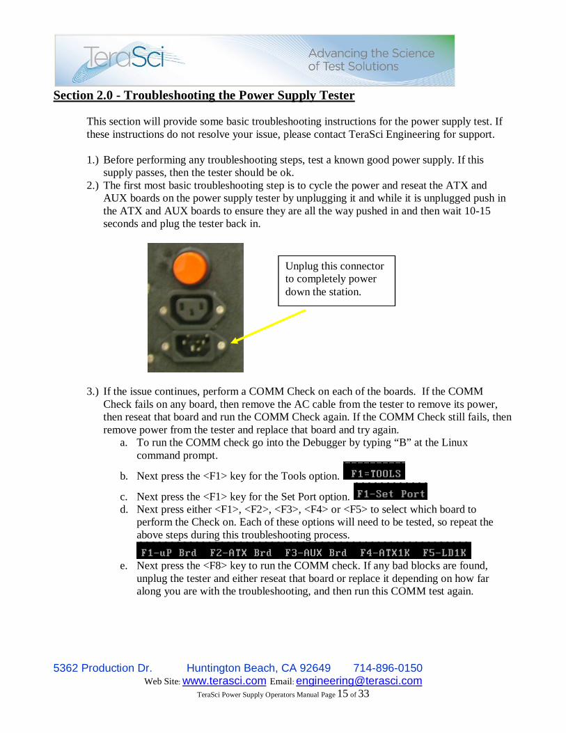
Section 2.0 - Troubleshooting the Power Supply Tester This section will provide some basic troubleshooting instructions for the power supply test. If these instructions do not resolve your issue, please contact TeraSci Engineering for support. 1.) Before performing any troubleshooting steps, test a known good power supply. If this
supply passes, then the tester should be ok. 2.) The first most basic troubleshooting step is to cycle the power and reseat the ATX and
AUX boards on the power supply tester by unplugging it and while it is unplugged push in the ATX and AUX boards to ensure they are all the way pushed in and then wait 10-15 seconds and plug the tester back in.
3.) If the issue continues, perform a COMM Check on each of the boards. If the COMM Check fails on any board, then remove the AC cable from the tester to remove its power, then reseat that board and run the COMM Check again. If the COMM Check still fails, then remove power from the tester and replace that board and try again.
a. To run the COMM check go into the Debugger by typing “B” at the Linux command prompt.
b. Next press the <F1> key for the Tools option.
c. Next press the <F1> key for the Set Port option. d. Next press either <F1>, <F2>, <F3>, <F4> or <F5> to select which board to
perform the Check on. Each of these options will need to be tested, so repeat the above steps during this troubleshooting process.
e. Next press the <F8> key to run the COMM check. If any bad blocks are found,
unplug the tester and either reseat that board or replace it depending on how far along you are with the troubleshooting, and then run this COMM test again.
Unplug this connector to completely power down the station.

5362 Production Dr. Huntington Beach, CA 92649 714-896-0150 Web Site: www.terasci.com Email: [email protected]
TeraSci Power Supply Operators Manual Page 16 of 33
4.) If the issue is a bad SATA or FLP connection, change the gray cable that connects this board, and test a known good supply. If the supply still fails for SATA or FLP, then replace the SATA or FLP board with a spare. NOTE: If the operator notices the light on the SATA or FLP board is flickering, then the cable connecting the board likely has a short in it and that cable will need to be replaced. Please ensure the operators are trained to catch this.
5.) If the issue is a bad AUX connection, then mark off that port and put a sticker over top of it, and do not use it. Then test a known good supply using any of the remaining AUX connections, the test will automatically detect which AUX connection is plugged in.
6.) For all other issues, please contact TeraSci Engineering Support.
Press this “F8”option to start the COMM check for the selected board.
If any Bad Blocks are found unplug the tester and either reseat or replace that board.
5362 Production Dr. Huntington Beach, CA 92649 714-896-0150 Web Site: www.terasci.com Email: [email protected]
TeraSci Power Supply Operators Manual Page 17 of 33
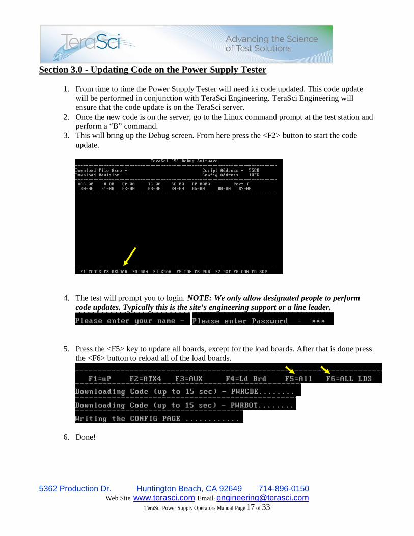
Section 3.0 - Updating Code on the Power Supply Tester
1. From time to time the Power Supply Tester will need its code updated. This code update will be performed in conjunction with TeraSci Engineering. TeraSci Engineering will ensure that the code update is on the TeraSci server.
2. Once the new code is on the server, go to the Linux command prompt at the test station and perform a “B” command.
3. This will bring up the Debug screen. From here press the <F2> button to start the code update.
4. The test will prompt you to login. NOTE: We only allow designated people to perform
code updates. Typically this is the site’s engineering support or a line leader.
5. Press the <F5> key to update all boards, except for the load boards. After that is done press
the <F6> button to reload all of the load boards.
6. Done!

5362 Production Dr. Huntington Beach, CA 92649 714-896-0150 Web Site: www.terasci.com Email: [email protected]
TeraSci Power Supply Operators Manual Page 18 of 33
Section 4.0 - Requesting new Profiles
From time to time your site will run across a Power Supply that does not yet have a profile created. When this happens, please contact TeraSci Engineering Support and let us know the CT Number and/or Assembly Part Number. If possible please also provide the Power Supply’s Specification document and/or a method for TeraSci to obtain this (i.e. HP’s MY PIM Engineering System). In some cases we can profile a new supply without a sample, but typically TeraSci will require a couple of known good samples to setup the profile. The samples will be sent to our office in Huntington Beach, and once we are done with them we will ship them back to the site.

5362 Production Dr. Huntington Beach, CA 92649 714-896-0150 Web Site: www.terasci.com Email: [email protected]
TeraSci Power Supply Operators Manual Page 19 of 33
3. Test Parameters The TeraSci power supply tester has several control files: MODELS.CSV, CONFIG.CSV and SCRIPT.CSV. The MODELS.CSV file contains the Assembly number and the 4 digit assembly codes (from the CT number) for the power supplies that have been configured for the tester. Every power supply that is supported by the tester must be in the MODELS.CSV. This file maps the assembly number (or CT code) to a CONFIG.CSV file name. The operator must enter a valid assembly number (or CT code) to start the power supply tester. The software looks up the assembly number in the MODELS.CSV and finds the CONFIG.CSV name. To add new supply to the TeraSci power supply tester you must add the assembly number, the 4 digit CT code, and the CONFIG.CSV name to the MODELS.CSV. The MODELS.CSV (and all other CSV’s) can be edited using Notepad or any other editor. The assembly number and CT code are copied from the supply. The CONFIG.CSV file name must be a new unique name. The term CONFIG.CSV is used here to define a file name for the power supply to be tested. Each power supply will have its own file name, generally the assembly number + CF and the .CSV. For the remainder of this section we will refer to the CONFIG.CSV and SCRIPT.CSV by these generic names. Of course these 2 names will not exist in an active system. To create a new CONFIG.CSV it is easiest to copy a CONFIG.CSV that is close to the same configuration of a configured supply. Of course name this new CSV with the same name you just entered into the MODELS.CSV. Open the new CONFIG.CSV with Notepad (or another editor). Each line of the CONFIG.CSV is a standalone value. The line starts with a label and has a number of operands. Each operand is separated by a comma and each line ends with a carriage return (and line feed).

5362 Production Dr. Huntington Beach, CA 92649 714-896-0150 Web Site: www.terasci.com Email: [email protected]
TeraSci Power Supply Operators Manual Page 20 of 33
Lines that start with a “;” are comment lines and any text on that line is ignored by the test software. The Label (a mnemonic) provides a means of mapping values between the CONFIG.CSV and the SCRIPT.CSV files. For example the SCRIPT file defines the test steps (the actions) and the CONFIG file provides the values for that action. The SCRITP file may define an action to apply a load to the 3.3 output voltage (RELAY is the action). The RELAY command will have an operand with a label (RLYMIN33). The CONFIG.CSV must contain the operand name (RLYMIN33) as a Label (the first thing on any line in the CONFIG file). That label (RLYMIN33) in the CONFIG file will also have a series of values (operands), in this case the address of the relay board and the amount of current required by the action. The CONFIG.CSV and the SCRIPT.CSV are used in conjunction with each other to provide a flexible method for testing the parameters of a power supply. This method allows the test engineer to adjust the setup and Pass / Fail parameters for testing a power supply without writing any code. It also provides a method to keep the criteria for each supply under test separate from all of the other supplies. The setup information in the CONFIG.CSV provides the load currents values for the power supply under test. There are two types of load currents, fixed values and selectable values. The load currents for -5V, -12V, and 5V Standby are fixed. The adaptor board has the load resisters for the fixed loads. To change these loads we change adaptor boards (which have different load resistors). The adaptor boards have ID numbers and the adaptor ID number is stored in the CONFIG.CSV. The load currents for 3.3V, 5V and 12V are defined by the CONFIG.CSV and controlled by the SCRIPT.CSV. That is to say the CONFIG.CSV defines three levels of load current for each of the three voltages. We define these load current values as: Minimum, Nominal and Maximum. This means the CONFIG.CSV defines 9 load current values. These values are defined by the power supply specification. Generally the power supply specification defines the maximum and nominal current for each of the voltage outputs of the supply. It is important to note that most power supplies will not operate at maximum current load on all of the output voltages simultaneously. That condition will exceed the maximum power output (wattage) of the supply. This condition (the maximum power

5362 Production Dr. Huntington Beach, CA 92649 714-896-0150 Web Site: www.terasci.com Email: [email protected]
TeraSci Power Supply Operators Manual Page 21 of 33
consumption) is a SCRIPT.CSV function and is not a parameter of the CONFIG.CSV. Therefore the maximum current values for each voltage in the CONFIG.CSV should be set to approximate the maximum continuous current for the specified voltage. The Pass / Fail information is used by the SCRIPT.CSV actions that measure a parameter. For example: the SCRIPT action CHKPF is used to see if the results of a previous action (ADC – measure a voltage) is within the acceptable limits for the power supply under test. CHKPF will have an operand such as DCMIN33. In the CONFIG.CSV file the label DCMIN33 will provide the maximum and minimum values that are acceptable for that test step. The following table contains the actions that are available in the SCRIPT file. Each of the actions may have an operand which is typically a LABEL that is defined in the corresponding CONFIG file. ACTIONS: PWRON – this script step will set the power supply power on line active. After activating the power supply the code will measure the time (in milliseconds) until the power supply power OK line goes active. The operand is always PWRGOOD (this label must be defined in the CONFIG.CSV) PWRGOOD supplies the time limits for the power OK line. DELAY – this actions cause the code to delay for n 25 millisecond increments. The operand is a numerical value from 1 to 255. RELAY – this action will set the current load for one of the three primary voltage channels (3.3V, 5V or 12V). The operand must be defined in the CONFIG.CSV. The operand defines the relay board (3=3.3V, 5=5V, and 2=12V) and the amount of current required. There are usually 3 levels of current defined for each channel, the minimum load, the nominal load, and the maximum load. ADC – this action cause the code to perform an ADC conversion on the specified channel. The operand defines the type of conversion (DC level or Ripple check), the

5362 Production Dr. Huntington Beach, CA 92649 714-896-0150 Web Site: www.terasci.com Email: [email protected]
TeraSci Power Supply Operators Manual Page 22 of 33
channel to be converted (3.3V, 5V, 12V, -5V, -2V, 5V Standby, or one of the Aux channels), and finally the pass fail limits for this conversion. CHKPF – this action is used to check the results of one of two previous actions. For PWRON action it checks the time for power good. For the ADC actions it checks the DC level or the Ripple. The CHKPF normally will have the same operand as the ADC action. If the CHKPF fails it will set the intermediate PF flag and the power supply PF flag. LBL – this action is used to log the results of a previous CHKPF action. The second operand is the field name in the Tracker Data Base where the results are stored (this operand is actually the placed in the TRK file as the field name). The third operand is the type of data to be placed in the Tracker Data Base field. The third operand has four conditions. “F” is used to put the intermediate PF flag into the TRK data. “P” is used to put the power good time into the TRK. “D” is used to put the DC level from an ADC conversion into the TRK. “R” is used to put the ripple value into the TRK. By convention the LBL action has four characters XXXX as the start of a field name. These four characters represent the state of the four RELAY boards. The first character is for the AC line value (L = Low line M=nominal line and H=High line). The second character is for the 3.3V, the third for the 5V and the fourth for the 12V. Again these can be three values L=minimal load, M=nominal load, and H=maximum load. PSOFF – this action moves the power supply on line to the inactive state. END OF LIST – this is not an action but defines the end of the SCRIPT file of the CONFIG.CSV file. Any steps defined beyond this point will not be executed. CONFIG File Definitions SCRIPT – this label is used to define the name of the SCRIPT.CSV file to be used with this CONFIG.CSV. PWRGOOD – this label is used to define the power on flag (P) and the limits for the power good pass fail time. The Power good pass fail time is defined in milliseconds, with the minimum time first and the maximum time second.

5362 Production Dr. Huntington Beach, CA 92649 714-896-0150 Web Site: www.terasci.com Email: [email protected]
TeraSci Power Supply Operators Manual Page 23 of 33
RLYOFF – this label is used to put all of the relay boards into the minimum load state. RLYxxx – this label is used to define which relay channel requires an action, and how mush current (load) is required. This label will have many names, one for each load for each channel. This label must have 2 operands, the first defines the channel (relay board) and must be 3 (3.3V), 5 (5V) or 2 (12V). The second operand is the amount of current required for this setup. The next section will define the discrete current increments available for different tester. Current Setup Procedure The relay boards have 4 switch-able loads and 1 fixed load. These are all resistive loads and the resistance will vary from tester to tester. The software in each test box has a table with the fixed current and the current for each of the 4 relays. The software will determine which relays to energize to get as close as possible to the value defined in the CONFIG file (RLYxxx Label) without going over that value. DCxxxx – this label is used to define ADC conversions for DC values, the channel to be converted, and the pass fail limits for this conversion. This Label is used by the ADC action and the CHKPF action. The first operand is a D to indicate that a DC conversion is required. The second operand is the channel to be converted and this can be 0 to 15 (see the table below). The third and fourth operands are used to set the pass fail limits for this conversion. The third operand is the minimum limit and the fourth is the maximum. Both of these operands are defined in mill volts. The tester has 4 ADC converters with 4 channels each for a total of 16 channels. The channels are defined as: Channel Voltage 0 3.3V 1 AUX1 12V 2 12V 3 -12V 4 5V 5 -5V

5362 Production Dr. Huntington Beach, CA 92649 714-896-0150 Web Site: www.terasci.com Email: [email protected]
TeraSci Power Supply Operators Manual Page 24 of 33
6 AUX1 5V 7 5V Standby 8 AUX2 12V 9 AUX3 12V 10 AUX4 12V 11 AUX2 5V 12 AC Line 13 AC Peak 14 AUX3 5V 15 AUX4 5V RIPxxx – ADC conversions for Ripple values, the channel to be converted, and the pass fail limits for this conversion. This Label is used by the ADC action and the CHKPF action. The first operand is a R to indicate that a Ripple conversion is required. The second operand is the channel to be converted and this can be 0 to 15. The third and fourth operands are used to set the pass fail limits for this conversion. The third operand is the minimum limit and the fourth is the maximum. Both of these operands are defined in mill volts.

5362 Production Dr. Huntington Beach, CA 92649 714-896-0150 Web Site: www.terasci.com Email: [email protected]
TeraSci Power Supply Operators Manual Page 25 of 33
Spare parts and Service
Following are pictures and descriptions of the primary components within the TeraSci Power Supply test system. The connecting points for replacement spare parts are easily identified within the system. PSU test station including Plexiglas protective cover. The Plexiglas cover provides a safety feature to prevent any possible sparks that might occur during the operation of the equipment.
Primary Test system components Brushed metal housing Internal Power Supply CPU Load Test & Micro controller PCB’s Triac AC controller
- AUX Connector PCB & - ATX Combo PCB 1,2,3,4
Plexiglas safety cover
5362 Production Dr. Huntington Beach, CA 92649 714-896-0150 Web Site: www.terasci.com Email: [email protected]
TeraSci Power Supply Operators Manual Page 26 of 33
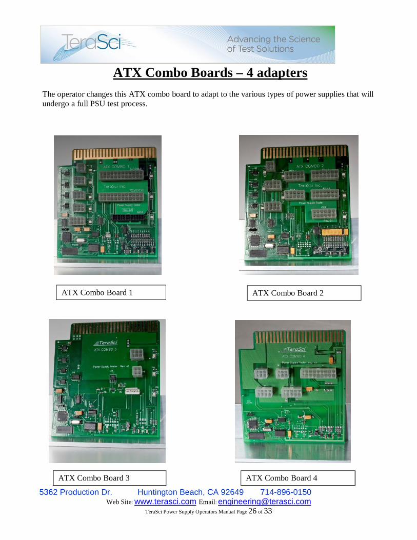
ATX Combo Boards – 4 adapters The operator changes this ATX combo board to adapt to the various types of power supplies that will undergo a full PSU test process.
ATX Combo Board 1 ATX Combo Board 2
ATX Combo Board 3 ATX Combo Board 4

5362 Production Dr. Huntington Beach, CA 92649 714-896-0150 Web Site: www.terasci.com Email: [email protected]
TeraSci Power Supply Operators Manual Page 27 of 33
AUX Connector Board
The AUX Connector board is inserted at the top of the main back plane board. This board will be exposed to the outside of the metal base with easy access to the actual power supplies that will be tested in the system.
5362 Production Dr. Huntington Beach, CA 92649 714-896-0150 Web Site: www.terasci.com Email: [email protected]
TeraSci Power Supply Operators Manual Page 28 of 33
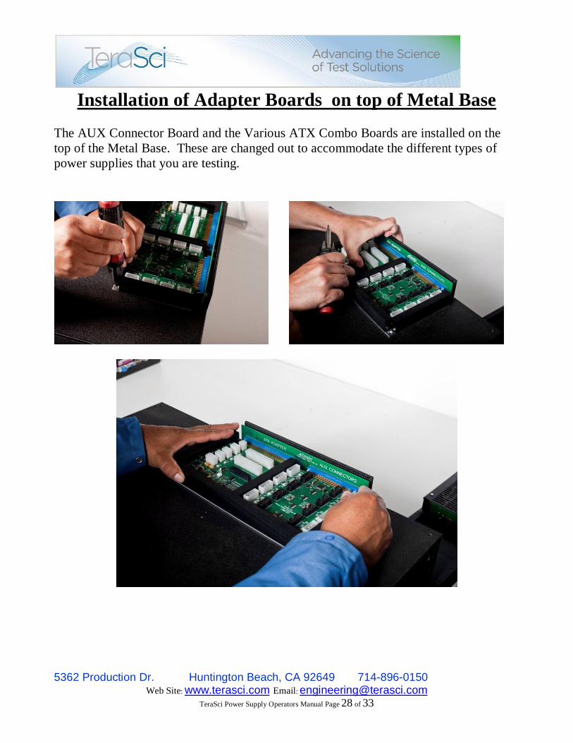
Installation of Adapter Boards on top of Metal Base The AUX Connector Board and the Various ATX Combo Boards are installed on the top of the Metal Base. These are changed out to accommodate the different types of power supplies that you are testing.

5362 Production Dr. Huntington Beach, CA 92649 714-896-0150 Web Site: www.terasci.com Email: [email protected]
TeraSci Power Supply Operators Manual Page 29 of 33
Internal Back Plane
Insertion point for ATX Adapter PCB’s
& AUX Connector PCB
ATX Combo Board insertion point AUX Board insertion point
5362 Production Dr. Huntington Beach, CA 92649 714-896-0150 Web Site: www.terasci.com Email: [email protected]
TeraSci Power Supply Operators Manual Page 30 of 33
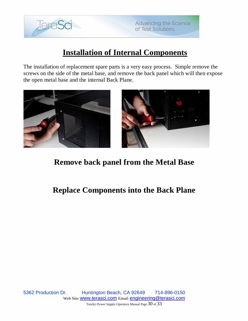
Installation of Internal Components
The installation of replacement spare parts is a very easy process. Simple remove the screws on the side of the metal base, and remove the back panel which will then expose the open metal base and the internal Back Plane.
Remove back panel from the Metal Base
Replace Components into the Back Plane

5362 Production Dr. Huntington Beach, CA 92649 714-896-0150 Web Site: www.terasci.com Email: [email protected]
TeraSci Power Supply Operators Manual Page 31 of 33

5362 Production Dr. Huntington Beach, CA 92649 714-896-0150 Web Site: www.terasci.com Email: [email protected]
TeraSci Power Supply Operators Manual Page 32 of 33
Internal Power Supply Cables
Connect all of the internal power supply cables to the back plane power connector points. Contact TeraSci Technical Support if you have any questions: [email protected]

5362 Production Dr. Huntington Beach, CA 92649 714-896-0150 Web Site: www.terasci.com Email: [email protected]
TeraSci Power Supply Operators Manual Page 33 of 33
Load Test PCBS’s
After removing the panel from the metal base, you can remove or insert replacemtn Load Test boards into the green back plane. If you have any questions about this process, contact the TeraSci Technical support and engineering teams for assistance.
Carefully insert the load test PCB’s into the Back plane, and push into place using your thumbs.
Load test boards Inserted into place.