
Tension Technology International Ltd - Test Report Technology International Ltd Consultants in...
48
Annex A Tension Technology International Ltd - Test Report
-
Upload
vuongnguyet -
Category
Documents
-
view
220 -
download
2
Transcript of Tension Technology International Ltd - Test Report Technology International Ltd Consultants in...
Annex A
Tension Technology International Ltd - Test Report


Tension Technology International Ltd
Consultants in Flexible Tension Member Systems
www.tensiontech.com
Chain inspection and testing for MAIB
TTI-IMLR-2010-663R
Date Rev. Description Prepared by Authorised by
26/05/2010 0 final report for issue to client IMLR REH
Distribution: Attention:
TTI Ltd. (author, file) IMLR, REH
MAIB

Chain inspection and testing for MAIB
ii
Summary
This report details the findings from inspection and testing on a failed 13 mm chain sling. Breaking load tests have been conducted on sections of the 13 mm sling which failed, and also on a 7 mm chain of the same geometry and grade, with a view to investigating the effect on strength of loading a chain bent over a pad‐eye.
Specific findings are:
Two breaking load measurements have been conducted on samples from the failed 13 mm chain sling, with an average result of 224.3 kN. Therefore the chain satisfied the minimum strength requirement for 13 mm grade 8 short link chain for lifting purposes (in accordance with BS EN 818‐2).
The fracture surfaces of the failed link were too corroded for detailed (microscopic) examination. However, the general appearance of the failure (gross plastic distortion) indicates a failure caused by high loading rather than fatigue. Subsequent testing indicated that the failure mechanism was in the form of an overload whilst the chain was doubled back on itself around a (pad‐eye) pin.
Two tests were conducted to break a length of 7 mm chain doubled over a pin (180° wrap) scaled to match the diameter of the pad‐eye. The average breaking strength of the chain in this condition was found to be 48.94 kN, a reduction of 25% in strength when compared with the straight chain strength.
These findings would equate to a breaking load of for the 13 mm sling in the doubled up condition of 336.5 kN.
Even though the doubled back chain configuration was found to have reduced the average breaking strength (BF) of the straight chain, at 75% of BF the residual strength was still in excess of the Working Load Limit by a factor of 3.
Although the strength of the doubled back chain was in excess of the same chain in the straight configuration, its ability to absorb (shock loading) energy in this configuration would be very considerably reduced. This finding is highly significant in the context of strain driven (e.g. marine) environments.
No investigation has been made into the effect on breaking load of variation in the rate of loading (e.g. shock loading), or for other test geometries (different pin diameters).

Chain inspection and testing for MAIB
iii
Contents
Summary ii
Contents iii
List of Tables iv
List of Figures iv
1 Introduction 1
2 Examination of the failed chain sling 2
3 Chain testing 5
3.1 Breaking load tests on sections of the 13 mm chain sling 5
3.2 Strength loss from operation around a pin 9
3.2.1 Chain strength reference test 11
3.2.2 Chain strength test over a pin 11
4 Discussion of results 13
5 Conclusions 17
6 References 18
Appendix A – Calibration certificate for 250 kN testing machine 19

Chain inspection and testing for MAIB
iv
List of Tables
Table 1: Measurement on links 1‐5 taken from failed chain sling compared with the requirements for lifting chain from BS EN 818‐2:1996. 6
Table 2: Results of the breaking load measurements on the 13 mm chain sling samples. 7
Table 3: Results of the breaking load measurements on the 7 mm chain. 11
Table 4: Results of the breaking load measurements on the 7 mm chain over a pin. 12
List of Figures
Figure 1: Section of the un‐failed chain. 1
Figure 2: Failed chain link. 1
Figure 3: Typical condition of the chain sling away from the failure point. 2
Figure 4: Link which would have been adjacent to failed link prior to sling failure. 2
Figure 5: Section of chain sling with failed link attached. 3
Figure 6: The link adjacent to the failed link can clearly be seen to be bent. 3
Figure 7: The failed link. 4
Figure 8: Notation used to define link geometry, from BS EN 818‐1 5
Figure 9: First 13 mm chain sample (links 1‐5) ready for strength measurement. 6
Figure 10: Load‐elongation relationship for second breaking load test (links 7‐11). 7
Figure 11: Typical appearance of a chain failure caused by pure tensile overload. 8
Figure 12: Agreed test configuration for the ‘bent over pin’ test. 9
Figure 13: Pad‐eye across which 13 mm chain was operating when it failed. 10
Figure 14: Sample MAIB06 in the machine ready for testing. 11
Figure 15: Sample MAIB06 after failure, the 5th (middle) of 9 links has failed. 12
Figure 16: Close up view of the failure region. Note that the link adjacent to the failed link is bent in the same manner as that found on the 13 mm chain sling. 12
Figure 17: Schematic diagram showing how the failed link and adjacent links would be affected by the action of the pin. 13
Figure 18: Load‐elongation relationship for the two pairs of 7 mm chain breaking load tests: straight and bent over a pin. 15

Chain inspection and testing for MAIB
1
1 Introduction
TTI Testing (the testing subsidiary of Tension Technology International) was contracted by the MAIB to undertake a review of a chain sling failure (see Figures 1 and 2 below). These Figures show the sling shortly after the failure: Figure 1 shows the chain with its two master links connected by a bow shackle, whilst Figure 2 provides a close up of the failed link.
The work required on the sling comprised two parts:
1. Examination of the failed link to establish whether the cause of failure was a single one off snatch (over) load or fatigue related.
2. Measurement the strength of the chain subject to both tensile and simultaneous transverse loading, such as if the link were in operation through a pad‐eye.
Figure 1: Section of the un-failed chain.
Figure 2: Failed chain link.

Chain inspection and testing for MAIB
2
2 Examination of the failed chain sling
The failed sling was sent to TTI Testing’s premises in Arbroath for inspection. Figure 3 below shows a section of the chain (labelled exhibit ref. No. 011101133), which was typical of the condition. A preliminary measurement showed it to be 13 mm chain. It can be seen that the chain had a superficial uniform coating of rust, which is entirely consistent with use in a marine environment. It is not thought that this level of rust would be sufficient to affect the chain’s performance. Otherwise the chain appeared in good order. In all, thirty two links were counted in this section of chain.
Figure 3: Typical condition of the chain sling away from the failure point.
Figure 4 shows the condition of the chain adjacent to the link which failed. It can be seen that at some stage in service, this link has been subject to forces out of the plane of the link sufficient to bend the link.
Figure 4: Link which would have been adjacent to failed link prior to sling failure.

Chain inspection and testing for MAIB
3
Figure 5 shows a photograph of the second section of chain sling with the failed link still attached. This length of chain was counted as a further 32 links plus the failed link, 33 in total. Figure 6 shows a close up on the link next to the failed link, it too can clearly be seen to be bent out of the plane of the link.
Figure 5: Section of chain sling with failed link attached.
Figure 6: The link adjacent to the failed link can clearly be seen to be bent.
Finally, Figure 7 below shows the condition of the failed link. It can be seen that the link has been subject to significant plastic deformation in the plane of the link. The indentation on the side (at the top of the image) is consistent with the link having being in operation over an edge or around a pin – i.e. in contact with a third body leading to a transverse load on the

Chain inspection and testing for MAIB
4
link. Unfortunately the fracture surface was too corroded to provide any indication of whether fatigue had taken place (the fracture surface is more corroded than in the photograph shown in Figure 2). However, the gross plastic deformation of the failed link and those either side of it are indicative of gross overload rather than fatigue.
Figure 7: The failed link.

Chain inspection and testing for MAIB
5
3 Chain testing
The testing on the chain was undertaken in two parts:
1. Testing of two sections of 13 mm chain taken from the failed sling; and,
2. Testing of a smaller chain of the same geometry and grade as the failed sling to investigate any possible strength loss from being broken over a pin.
3.1 Breaking load tests on sections of the 13 mm chain sling Two samples each 5 links long were removed from the section of the sling shown in Figure 3 for checking the geometry and measurement of the breaking load. Links 1 to 12 were removed; link 1 being that at the connector end, and links 6 and 12 being cut (providing samples of links 1‐5 and 7‐11).
Measurements of the geometry (refer to Figure 8 for notation) were made on links 1‐5. These results are presented in Table 1. It can be seen that the link geometry was in accordance with BS EN 818‐2.
Figure 8: Notation used to define link geometry, from BS EN 818-1

Chain inspection and testing for MAIB
6
link no. dm (mm) (2 mutually perpendicular readings)
pitch, P (mm)
internal width, w1 (mm)
width over weld, w2 (mm)
1 12.84 13.09 39.64 18.10 44.42
2 12.84 13.12 39.49 18.36 44.26
3 12.83 13.10 39.18 18.40 44.56
4 12.96 13.13 39.14 18.43 44.66
5 12.91 13.07 39.33 18.40 44.65
specified by BSEN818-2
13 ± 0.52 39 ± 1.2 16.9 min 48.1 max
Table 1: Measurement on links 1 -5 taken from failed c hain sling compared with the req uirements for lifting chain from BS EN 818-2:1996, Table 2.
The samples were broken in accordance with BS EN 818‐1. The samples were loaded at a uniform loading rate until failure. A loading rate equivalent to 10 N/mm2/s was used. As the nominal area of the 13 mm chain is 265 mm2, this equates to a loading rate of 2.65 kN/s.
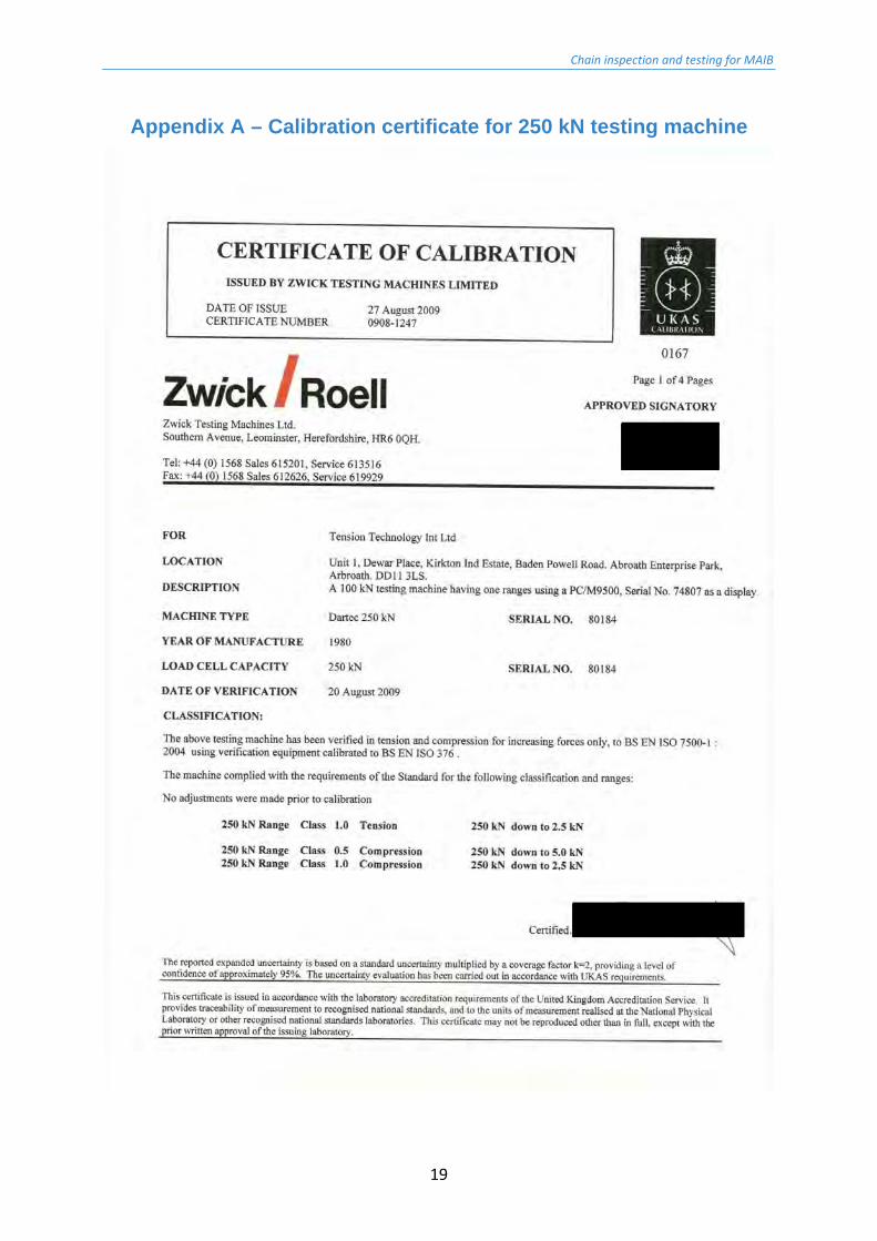
Figure 9 shows the sample in the 250 kN testing machine at TTI Testing’s facility in Arbroath. A calibration certificate for this equipment is presented in Appendix A.
Figure 9: First 13 mm chain sample (links 1-5) ready for strength measurement.

Chain inspection and testing for MAIB
7
Figure 10 shows the typical load‐elongation relationship, in this case for the second breaking load test. The graph is characterised by a bilinear ‘curve’. The first part of the graph is the ‘elastic’ section up to approx. 160 kN load (if the load is reduced before exceeding this limit the load‐elongation characteristic will return back along this initial line). The second shallower gradient line is associated with plastic deformation. Thus beyond the load of 160 kN the chain would suffer permanent deformation (distortion) if subsequently unloaded.
Figure 10: Load-elongation relationship for second breaking load test (links 7-11).
Results for the breaking load tests are presented in Table 2. With an average breaking strength of 224.3 kN from the two tests, it can be seen that the chain satisfies the requirement of 212 kN for grade 8 strength chain.
Sample No. gauge length, l (mm) breaking load (kN) elongation, A (%)
links 1-5 195 224.0 -
links 7-11 195 224.7 20
BS EN 818-2 N/A 212* 20**
* minimum, from BS EN818-2, Table 5 column 4, ** minimum, from section 5.4.2.
Table 2: Results of the breaking load measurements on the 13 mm chain sling samples.

Chain inspection and testing for MAIB
8
Figure 11 shows the appearance of the chain after failure (second breaking load test). The appearance is quite characteristic, with all links elongated and the parallel sides of the links pulled inwards. The failed link has yielded obliquely (suggesting a shear failure) at the area of interlink contact, whilst the un‐failed link (number 9) has a heavy indent at the end from the failed link.
Figure 11: Typical appearance of a chain failure caused by pure tensile overload.

Chain inspection and testing for MAIB
9
3.2 Strength loss from operation around a pin With the benefit of inspection of the chain (reported in section 2), and subsequent discussions with the MAIB, it seems likely that the chain was operated doubled back on itself over a pin (pad‐eye) through 180°, rather than deflected (at a much lower angle) around a pad‐eye as originally understood. This theory is supported on reviewing Figure 1, which shows both Master links on the same shackle; and additionally, the fact that there were 32 links in each section of the sling either side of the failed link. Accordingly, it was agreed with the MAIB to vary the test configuration from that originally proposed ( ).
A further complication was that the chain was larger than was thought when the initial scope of work was prepared, meaning that it was very likely that a test on a doubled back section of the chain would result in a configuration with a breaking load beyond the capacity of the test machine. Since the investigation as to whether there was any strength loss was general to chain rather than the specific failure, it was agreed to carry out this part of the investigation on a smaller chain (nominal 7 mm), but one which had the same geometry and material tensile grade. Figure 12 shows the agreed test geometry. The two smaller red circles show the location of the pins holding the sample into the test fitting, whilst the larger shaded circle, the pin representing the pad eye bar.
Figure 12: Agreed test configuration for the ‘bent over pin’ test.
Direction of Test load

Chain inspection and testing for MAIB
10
It should be noted that the test geometry shown in Figure 12 was selected to try to model the loading configuration of the failed link based on the post failure examination, and in particular the transverse loading evident in the plane of the link. If a chain is doubled over a bar there are clearly a number of configurations which the chain might adopt: with the centre link in any position from vertical (as shown) to horizontal or any angle in between. As the load is applied to the chain it will tend to straighten along its axis, in that adjacent links will tend to align with their axes mutually perpendicular (this assumes that there was no pre‐twist in the chain which would complicate things further).
Another point which should be made is that the length of the chain (an odd number of links) will have had an effect on the way in which the chain was positioned over the pad‐eye. If there had been an even number of links in the chain sling the geometry and loading would have been different again.
Figure 13 shows a picture of the pad eye received from the MAIB. From this photograph it was estimated that the pad eye bar diameter was 41 mm. Therefore, in the test a pin diameter of (7/13) × 41 = 22 mm was used.
Figure 13: Pad-eye across which 13 mm chain was operating when it failed.

Chain inspection and testing for MAIB
11
3.2.1 Chain strength reference test
In order to provide a reference strength, two breaking strength tests were undertaken on the 7 mm grade 8 chain. The loading rate was the same as that used in the earlier tests on the 13 mm chain (i.e. 10 N/mm2/s), so 0.77 kN/s was used. The results from these tests are presented in Table 3: the average breaking load was 65.23 kN.
Sample No. gauge length, l (mm) breaking load (kN) Elongation, A (%)
1 (MAIB04) 105.5 65.32 23
2 (MAIB05) 105.0 65.14 21
Table 3: Results of the breaking load measurements on the 7 mm chain.
3.2.2 Chain strength test over a pin
The test set up used for the breaking load test over a pin is shown in Figure 14. The samples were 9 links long (as shown in Figure 12) and arranged so that the weld of the middle link was at the top (i.e. clear of the pin).
Figure 14: Sample MAIB06 in the machine ready for testing.
Two breaking strength tests were conducted in this configuration. The results are presented in Table 4. It can be seen that the average breaking load of the chain in this configuration was 48.94 kN. Comparing this average to the results shown in Table 3, it can be seen that there was a strength loss of 25%.

Chain inspection and testing for MAIB
12
Sample No. sample length (no. links)
assembly breaking load (kN)
chain breaking load (kN)
3 (MAIB06) 9 98.18 49.09
4 (MAIB07) 9 97.55 48.78
Table 4: Results of the breaking load measurements on the 7 mm chain over a pin.
Figures 15 and 16 show the failed sample. The failed link is the 5th, the middle link of the sample which was on the pin during the test. The appearance of the failed link is very similar to that of the 13 mm sling failure (Figure 7). As with the 13 mm chain one side of the chain is bent to conform to the profile of the pin. In Figure 16 it can be seen that the link adjacent to the failed link has been bent out of plane and in the same direction as was found in the 13 mm sling (see Figure 6). These similarities suggest that the test is an accurate model of what happened in service.
Figure 15: Sample MAIB06 after failure, the 5th (middle) of 9 links has failed.
Figure 16: Close up view of the failure region. Note that th e link adjacent to the failed link is bent in the same manner as that found on the 13 mm chain sling.
Chain inspection and testing for MAIB
13
4 Discussion of results
This study set out to address two questions which had arisen as the result of the failure of a chain sling:
1. Was the cause of failure a single one off snatch (over) load or fatigue related?
2. What is the effect on the strength of the chain if it is subject to both tensile and simultaneous transverse loading, such as if the chain were in operation through a pad‐eye?
Tests were conducted on the two sections of chain taken from the failed sling. These established that the chain strength met the requirements for grade 8 lifting chain. This information was used to source a suitable chain for further tests.
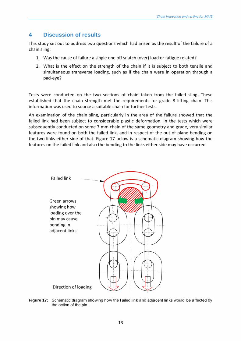
An examination of the chain sling, particularly in the area of the failure showed that the failed link had been subject to considerable plastic deformation. In the tests which were subsequently conducted on some 7 mm chain of the same geometry and grade, very similar features were found on both the failed link, and in respect of the out of plane bending on the two links either side of that. Figure 17 below is a schematic diagram showing how the features on the failed link and also the bending to the links either side may have occurred.
Figure 17: Schematic diagram showing how the f ailed link and adjacent links would be affected by the action of the pin.
Failed link
Green arrows showing how loading over the pin may cause bending in adjacent links
Direction of loading

Chain inspection and testing for MAIB
14
Testing determined that the total load at which the 7 mm chain bent over the pin broke was 97.87 kN (average of two tests). However since the chain was doubled through 180° this means that the load in each leg of the chain was half this figure, i.e. 48.94 kN.
Care should be taken when interpreting these results. The loading on the chain link in the area of the pin is complicated, it is affected by:
the adjacent links which provide load to it from different angles (i.e. the load is not axial any more);
by the transverse compressive load from the pin; and,
by friction.
So it is not straightforward to say what the load is in that specific link. The practical result, however, is that when the links some way from the pad‐eye have 75% of their usual breaking load, the chain fails.
For the 13 mm chain this result would imply a failure load of the doubled over the pin ‘assembly’ of 2 × 0.75 × 224.3 = 336.5 kN (not the 448 kN which would be obtained if two straight chains were used in parallel).
It should be noted that a strength of 75% of the usual breaking force (BF) is still well in excess of the working load limit (WLL) as specified in BS EN818‐2. For a single 13 mm chain the WLL is 52 kN or 25% BF.
Turning to the ‘straight’ links in the remainder of the chain, an interesting question is: if these have experienced 75% of their failure load would there be any evidence of this?
Figure 10 shows the load‐elongation plot for the 13 mm chain when tested to failure. It may be seen that at 75% of the breaking load (168 kN) the chain has only just entered the plastic region (this is marked by the change of slope on the graph). Review of the graph shows that the permanent plastic elongation would be 1% at most at this load (the difference between the total elongation and the elastic recoverable elongation) – which equates to 0.39 mm for a 13 mm (39 mm pitch) link. This level of permanent deformation is very low, and well within the ± 1.2 mm allowed by BS EN818‐2. It is therefore difficult to conclude anything concerning the chain loading history other than to say that it is possible that the other chain links could remain within geometrical tolerance at the loads thought to have caused failure of the link on the pin.
The observation that the majority of the chain links in the bent over pin test were not loaded sufficiently to cause appreciable plastic deformation leads to an important point. This point is best illustrated by consideration of the load‐elongation plots for the two types of 7 mm chain tests, Figure 18.
Figure 18 shows the two pairs of results for the straight chain (MAIB04 and MAIB05) and those doubled over the pin (MAIB06 and MAIB07). The straight chain test relationship has a bilinear shape very much like that for the 13 mm chain (Figure 10), which is to be expected.
Considering now the results for the doubled over pin relationship, the curve is also bilinear, the initial stiffness is more than the single straight chain since the load in the chain is now shared between two parts. However, the transition point between the elastic and plastic behaviour is much less marked. The reason for this is that the majority of the chain links

Chain inspection and testing for MAIB
15
remain at loads below their plastic limit for nearly the whole test. The link on the pin, and possibly the two either side suffer all the plastic deformation before failure.
As a result of this, the total ultimate elongation to failure of the bent over pin assembly is considerably reduced at 7.7% (average) compared with the 22% average elongation of the straight test. The loss of a clear transition point and the reduction in percentage overall elongation at failure will be even more noticeable for a longer chain (such as one of 65 links) where one link is only 1.5% of the number of links as opposed to a 9 link sample where one link is 11% of the total.
The practical implications for the load‐deflection characteristic are in a consideration of the capacity of the chain to absorb energy – such as from a shock load. In general energy is absorbed by components stretching or elongating in response to loading. For a given strength, more compliant structures (those which stretch more under load) are able to absorb more energy than stiffer structures.
The energy at failure in the chain is given by the area under the curve – it can be seen that even though the failure load of the bent over pin assembly is higher than the straight chain, the area under the curve is far less. (This area would be lower still for the longer chain where the relationship tends to a straight line of the initial gradient.)
Hence, although the bent over pin configuration is prima facie at least as strong as (even stronger than) a straight chain configuration, it is also much more vulnerable to dynamic shock overloads. For otherwise identical configurations, in a displacement driven loading environment (such as the marine environment) a stiffer sample will experience much higher peak loads.
Figure 18: Load-elongation relationship for the two pairs of 7 mm chain breaking load tests: straight and bent over a pin.

Chain inspection and testing for MAIB
16
Final comments which must be made:
The results of the test reported here are specific to the test configurations used. It is to be expected that different levels of strength loss would be obtained by varying the size of the pin diameter. The pin size used here was selected to model (by scaling from a photograph) the pad‐eye involved in this sling failure.
The other variable which has not been considered is the effect of loading rate. A distinction is made between high loading rates as opposed to very high snatch loadings (which may also have a high loading rate) but where the peak load is also very high – much higher than the static factor of safety. The chain sling must have experienced a load in excess of its straight WLL in order for it to have failed.

Chain inspection and testing for MAIB
17
5 Conclusions
1. An inspection has been conducted on the failed chain sling which was sent to TTI Testing for examination.
2. Two breaking load measurements have been conducted on samples from the failed 13 mm chain sling, with average result of 224.3 kN.
3. With a breaking load in excess of 212 kN the chain satisfied the minimum requirement for grade 8 short link chain for lifting purposes (in accordance with BS EN 818‐2).
4. The fracture surfaces of the failed link have become too corroded for detailed examination. However, the general appearance of the failure (gross plastic distortion) indicates a failure caused by high loading rather than fatigue.
5. Subsequent testing indicated that the failure mechanism was in response to an overload whilst the chain was doubled back on itself around a (pad‐eye) pin.
6. Two tests were conducted to break a length of 7 mm chain doubled over a pin (180° wrap) scaled to match the diameter of the pad‐eye.
7. The average breaking strength of the chain was found to be 48.94 kN, a reduction of 25% in this configuration compared with the straight chain.
8. These findings would equate to a static breaking load for the 13 mm sling in the doubled up condition of 2 × 0.75 × 224.3 = 336.5 kN.
9. No investigation has been made into the effect on breaking load of variation in the rate of loading (e.g. shock loading), or for other test geometries (varying pin diameter).
10. Even though the doubled back chain configuration was found to have reduced the average breaking strength of the straight chain, at 75% BF the residual strength was still in excess of the WLL by a factor of 3. Therefore, it can be stated that in order for the chain sling to have failed it was loaded beyond its safe working load as specified by BS EN818‐2.
11. As the damage to the chain in the bent over pin configuration is very localised this seriously reduces the chain’s capacity to absorb high energy shock loads. This consideration is very significant in a strain driven loading environment such as the marine environment.

Chain inspection and testing for MAIB
18
6 References
BS EN 818‐1:1996+A1:2008 Short link chain for lifting purposes – Safety – Part 1: General conditional of acceptance, British Standards Institute, 15th November1996 and 30th September 2008.
BS EN 818‐2:1996+A1:2008 Short link chain for lifting purposes – Safety – Part 2: Medium tolerance chain for chain slings – Grade 8, British Standards Institute, 15th April 1997 and 30th September 2008.
Ridge, I.M.L. Fibre rope and chain testing for MAIB, Tension Technology International document no. TTI_IMLR_2010_663, 15th March 2010.
Chain inspection and testing for MAIB
19
Appendix A – Calibration certificate for 250 kN testing machine

Chain inspection and testing for MAIB
20

Chain inspection and testing for MAIB
21

Chain inspection and testing for MAIB
22
Annex B
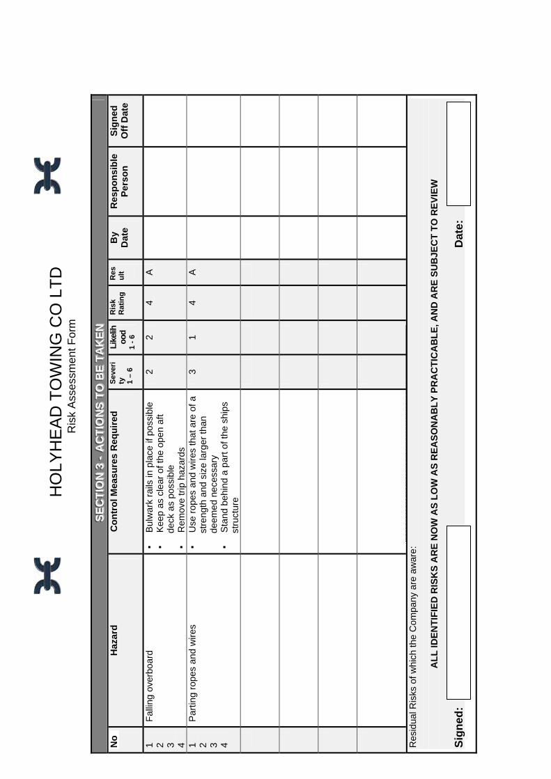
Risk assessment form

HOLYHEAD TOWING CO LTD Risk Assessment Form
SSSEEECCCTTTIIIOOONNN 111 --- PPPRRROOOCCCEEESSSSSS /// AAARRREEEAAA IIINNNFFFOOORRRMMMAAATTTIIIOOONNN
RREEFF NNOO –– RRAA000011 AASSSSEESSSSMMEENNTT TTIITTLLEE --
TTOOWWIINNGG PPRROOCCEESSSS DDEESSCCRRIIPPTTIIOONN && TTAASSKK LLIISSTT ––
11.. TToowwiinngg aannyy ffllooaattiinngg oobbjjeecctt oovveerr tthhee sstteerrnn 22.. TToowwiinngg aannyy ffllooaattiinngg oobbjjeecctt aalloonnggssiiddee 33.. AAssssiissttiinngg vveesssseellss aalloonnggssiiddee 44.. OOppeerraattiinngg aass sstteerrnn ttuugg oovveerr tthhee sstteerrnn RREEGGIISSTTEERR OOFF EEQQUUIIPPMMEENNTT && AANNCCIILLLLAARRIIEESS UUSSEEDD --
11.. TToowwiinngg hhooookk 22.. TToowwiinngg wwiinncchh 33.. SSaaffeettyy bbooww sshhaacckklleess 44.. WWiirree ppeennnnaannttss 55.. RRooppee sspprriinngg 66.. CChhaaiinn bbrriiddlleess AASSSSOOCCIIAATTEEDD PPEERRSSOONNAALL PPRROOTTEECCTTIIVVEE EEQQUUIIPPMMEENNTT –– (To be worn as a minimum) ▪▪ SSaaffeettyy BBoooottss ▪▪ GGlloovveess ▪▪ LLiiffeejjaacckkeett ▪▪ HHaarrdd hhaatt EEMMPPLLOOYYEEEESS && OOTTHHEERRSS AATT RRIISSKK
AAnnyy ppeerrssoonnnneell oonn ddeecckk AARREEAA ((SS)) IINNVVOOLLVVEEDD
DDeecckk AARREEAA RRAA RREEFFEERREENNCCEE --
AAllll aarreeaass
AADDDDIITTIIOONNAALL SSPPEECCIIFFIICC AASSSSEESSSSMMEENNTT RREEQQUUIIRREEMMEENNTTSS &&RREEFFEERREENNCCEESS::
CCOOSSHHHH:: NNOOIISSEE:: GGEENNEERRIICC AASSSSEESSSSMMEENNTTSS:: OOTTHHEERR::

FFIIRREE && FFIIRRSSTT AAIIDD IINNFFOORRMMAATTIIOONN:: FFIIRREE FFIIGGHHTTIINNGG EEQQUUIIPPMMEENNTT AAVVAAIILLAABBLLEE IINN AARREEAA::
NNEEAARREESSTT EEMMEERRGGEENNCCYY EEXXIITT:: NNEEAARREESSTT LLIIFFEEBBUUOOYY NNEEAARREESSTT FFIIRRSSTT AAIIDD KKIITT:: SSPPEECCIIFFIICC LLEEGGIISSLLAATTIIOONN WWHHEERREE KKNNOOWWNN -- CCooddee ooff SSaaffee WWoorrkkiinngg PPrraaccttiicceess ffoorr MMeerrcchhaanntt SSeeaammeenn SSOOUURRCCEESS OOFF IINNFFOORRMMAATTIIOONN WWHHEERREE KKNNOOWWNN –– MMGGNN 1188((MM)) MM771188 MM11440066 MM11553311
LLOOCCAATTIIOONN OOFF RRIISSKK AASSSSEESSSSMMEENNTT --
SShhiippss lliibbrraarryy iinn tthhee wwhheeeellhhoouussee HHTTCC mmaaiinn ooffffiiccee DDAATTEE OOFF AASSSSEESSSSMMEENNTT --
2200 MMaarrcchh 22000066 RREEVVUUEE –– MMaarrcchh 22000077
UUnnlleessss tthheerree iiss aa ssiiggnniiffiiccaanntt cchhaannggee ttoo tthhee pprroocceessss oorr aann aacccciiddeenntt oorr nneeaarr mmiissss,, iinn wwhhiicchh ccaassee tthhee rreevviieeww sshhoouulldd bbee aass ssoooonn aass pprraaccttiiccaabbllee tthheerreeaafftteerr.. AASSSSEESSSSOORR:: NNAAMMEE::
SSIIGGNNAATTUURREE::
AANNYY OOTTHHEERR IINNFFOORRMMAATTIIOONN -- AAllll ttoowwaaggee ooppeerraattiioonnss sshhoouulldd bbee ccaarrrriieedd oouutt wwiitthh dduuee rreeggaarrdd ttoo tthhee wweeaatthheerr ccoonnddiittiioonnss.. AAllll eeqquuiippmmeenntt iinncclluuddiinngg,, bbuutt nnoott lliimmiitteedd ttoo,, rrooppeess,, wwiirreess,, sshhaacckklleess,, cchhaaiinnss,, ttoowwiinngg hhooookkss,, wwiinncchh bbrraakkeess aanndd qquuiicckk rreelleeaassee ssyysstteemmss sshhoouulldd bbee cchheecckkeedd rreegguullaarrllyy aanndd aannyy ddeeffeeccttss rreeppoorrtteedd ttoo tthhee MMaasstteerr aanndd aa CCoommppaannyy SSuuppeerriinntteennddeenntt aass ssoooonn aass ppoossssiibbllee.. AAllll ssaaffeettyy eeqquuiippmmeenntt,, iinncclluuddiinngg bbuutt nnoott lliimmiitteedd ttoo,, lliiffeerraaffttss,, lliiffeebbuuooyyss,, JJaassoonn’’ss ccrraaddllee,, iinnffllaattaabbllee lliiffeejjaacckkeettss aanndd PPPPEE sshhoouulldd bbee cchheecckkeedd aass ppeerr tthhee CCoommppaannyy SSOOLLAASS rreeppoorrtt ffoorrmmss,, aannyy ddeeffeeccttiivvee oorr oovveerrdduuee eeqquuiippmmeenntt sshhoouulldd bbee rreeppoorrtteedd ttoo tthhee MMaasstteerr aanndd aa CCoommppaannyy SSuuppeerriinntteennddeenntt aass ssoooonn aass ppoossssiibbllee..

HO
LYH
EA
D T
OW
ING
CO
LT
D
Ris
k A
sses
smen
t F
orm
SS SEE E
CC CTT T
II I OO ONN N
22 2 -- -
HH HAA A
ZZ ZAA A
RR RDD D
II IDD D
EE ENN N
TT TII I FF F
II I CC CAA A
TT TII I OO O
NN N && &
CC COO O
NN NTT T
RR ROO O
LL L
No
Tas
k / A
ctiv
ity
H
azar
d
Po
ten
tial
H
arm
Sev
erity
0
– 5
Lik
eli
hoo
d
0
- 5
Rat
ing
Co
ntr
ol
Mea
sure
s
Res
ult
Fal
ling
over
boar
d
Dro
wni
ng
4 2
8 ▪
Tra
ined
per
sonn
el
▪ L
ifeja
cket
s to
be
wor
n ▪
Life
buo
ys to
be
kept
near
by
B
Par
ting
rope
s an
d w
ires
Whi
p in
jury
3 2
6 ▪
Use
onl
y ro
pes
and
wire
s th
at
are
in g
ood
cond
ition
▪
K
eep
wel
l cle
ar o
f wor
king
ar
ea u
nles
s ab
solu
tely
ne
cess
ary
B
Sud
den
tight
enin
g of
rop
e or
wire
fr
om a
n un
expe
cted
dire
ctio
n C
rush
inju
ry
3 1
3 ▪
Be
awar
e of
the
posi
tion
of
t
he to
w a
t all
times
▪
Do
not a
llow
rop
es o
r w
ires
to
t
rail
in th
e w
ater
by
way
of t
he
p
rope
llers
A
Rop
es a
nd w
ire m
ay c
ause
a tr
ip
haza
rd
Trip
or
fall,
pos
sibl
y on
to
a sh
arp
surf
ace
or o
ver
the
side
2 1
2 ▪
Goo
d ho
usek
eepi
ng. C
oil a
ll
rop
es w
hen
not i
n us
e A
1
Tow
ing
any
float
ing
obje
ct o
ver
the
ster
n
Hea
ving
line
s us
ed fo
r co
nnec
tion
may
be
wei
ghte
d H
ead
inju
ry
2 1
2
S
afet
y he
lmet
s to
be
wor
n A
As
1
2 T
owin
g a
float
ing
obje
ct a
long
side
Mak
ing
rope
s fa
st o
n bi
tts /
bolla
rds
Cru
shed
fing
ers
3 1
3
K
eep
hand
s an
d fin
gers
wel
l
cle
ar o
f bol
lard
s A

3 A
ssis
ting
vess
els
alon
gsid
e A
s 1
4 O
pera
ting
as s
tern
tug
over
the
ster
n B
roac
hing
lead
ing
to c
apsi
ze
Dro
wni
ng
4 1
4
L
ifeja
cket
s to
be
wor
n
G
og r
ope
to b
e us
ed
Ens
ure
that
qui
ck r
elea
ses
are
wor
king
A
LL
ii kkee
ll iihh
oooo
dd KK
eeyy
SSee
vvee
rr iitt yy
KKee
yy
RRee
ssuu
ll tt KK
eeyy
0 Im
pro
bab
le O
cc
urr
ence
0
Del
ay
1 U
nlik
ely
1 M
ino
r In
jury
/ies
0 –
5 (A
) A
DE
QU
AT
E C
ON
TR
OL
, MO
NIT
OR
2 P
oss
ible
2
Lo
st T
ime
Inju
ry/i
es
3 L
ikel
y 3
Maj
or
Inju
ry/ie
s
6 –
15
(B)
AD
DIT
ION
AL
CO
NT
RO
L R
EQ
UIR
ED
4 V
ery
Lik
ely
4 F
atal
ity
/ Dis
abli
ng
Inju
ry
5 A
lmo
st
Cer
tain
5
Mu
ltip
le F
ata
lity
16 –
25
(C)
AD
DIT
ION
AL
CO
NT
RO
LS
A P
RIO
RIT
Y
HO
LYH
EA
D T
OW
ING
CO
LT
D
Ris
k A
sses
smen
t F
orm
SS SEE E
CC CTT T
II I OO ONN N
33 3 -- -
AA A
CC CTT T
II I OO ONN N
SS S TT T
OO O BB B
EE E TT T
AA AKK K
EE ENN N
N
o
Haz
ard
Co
ntr
ol M
easu
res
Req
uir
ed
S
eve
rity
1
– 6
Lik
elih
ood
1
- 6
Ris
k
Rat
ing
R
esu
lt
By
Dat
e
Res
po
nsi
ble
P
erso
n
Sig
ned
O
ff D
ate
1 2 3 4
Fal
ling
over
boar
d ▪
B
ulw
ark
rails
in p
lace
if p
ossi
ble
▪
Kee
p as
cle
ar o
f the
ope
n af
t
de
ck a
s po
ssib
le
▪
Rem
ove
trip
haz
ards
2 2
4 A
1 2 3 4
Par
ting
rope
s an
d w
ires
▪
Use
rop
es a
nd w
ires
that
are
of a
st
reng
th a
nd s
ize
larg
er th
an
deem
ed n
eces
sary
▪
S
tand
beh
ind
a pa
rt o
f the
shi
ps
stru
ctur
e
3 1
4 A
Res
idua
l Ris
ks o
f whi
ch th
e C
ompa
ny a
re a
war
e:
A
LL
IDE
NT
IFIE
D R
ISK
S A
RE
NO
W A
S L
OW
AS
RE
AS
ON
AB
LY
PR
AC
TIC
AB
LE
, AN
D A
RE
SU
BJE
CT
TO
RE
VIE
W
Sig
ned
:
Dat
e:

Annex C
Marine Guidance Note 308 (M&F)


- 1 -
MARINE GUIDANCE NOTE
MGN 308 (M+F)
MOORING, TOWING OR HAULING EQUIPMENT ON ALL VESSELS - SAFE INSTALLATION AND SAFE OPERATION Notice to all Builders, Repairers, Owners, Operators, Masters, Skippers, Officers and Crew of Merchant Ships, Yachts (Motor and Sail) and Fishing Vessels. This notice supersedes Merchant Shipping Notice M.718
Summary This Guidance Note provides updated advice on the safe installation, maintenance and use of mooring, towing and hauling equipment. It emphasises the importance of seeking expert advice on the repair and maintenance of equipment. It also advises that risk assessments which cover the use of mooring equipment should in particular take full account of the potential dangers of bights in mooring warps and of “Snap-Back” Zones.
1. Introduction 1.1. Operations such as mooring, towing and hauling (including trawling operations) impose
great loads on ropes, warps, gear and equipment. The circumstances of recent accidents show that greater emphasis should be given to considering the safety aspects of mooring and towing systems as a whole, rather than the individual safety aspects of component parts. Hence the system should include the safety of windlasses, winches, bollards and fairleads, their construction and their attachment to a vessel’s structure.
2. Design and Installation of Mooring Equipment 2.1 Winches or windlasses should be constructed to give warning of undue strains by
stalling at well below half the designed maximum safe working load of the weakest element in the system (e.g. bollard, fairlead, shackle, holding down bolt, etc.) and to afford further protection by walking-back at about half the design load (e.g. breaking strength of the mooring rope, tow line or hawser which ever is applicable). For Example: A winch or windlass capable of a 10 tonne pull should be fitted with a rope having a “breaking strain” of 20 tonnes or more.

- 2 -
2.2 The layout of the installations should be such as to avoid the need for anyone to be stationed or to work in the bight of warp or rope formed by the lead from the winch or windlass round and through the fairleads and over-side. The consequences of failure in any part of the system should be carefully considered and effective precautions taken.
2.3 Pedestal roller fairleads, lead bollards and mooring bitts should be: (a) Properly designed to meet all foreseeable operational loads and conditions;
(b) Correctly sited, wherever practicable this should enable only one line to need to be used on each item;
(c) Effectively secured to a part of the ship's structure which has been suitably strengthened; and (d) Effectively maintained. 2.4 The advice in paragraph 2.3 reflects the outcome of Marine Accident Investigation Branch
accident investigations which have found the following failures of equipment:-
(a) fracture of a roller pin due to corrosion fatigue. The place at which the fracture occurred was located at a sharp change of section machined at the lower end. Because this was located just below the housing surface it was inaccessible for inspection and maintenance;
(b) failure of the welding between a fairlead pedestal and the deck due to
inadequate preparation and poor welding; and
(c) failure of a bollard which together with its supporting pad piece was pulled out of the deck as a result of poor material selection and weld procedures during repairs and an inadequate supporting structure to cope with the service loads.
3. Repair and Maintenance 3.1 Owners, operators, masters and skippers should ensure that all mooring, towing and
hauling equipment, including ropes and warps, are covered by a regular maintenance programme. Equipment should be regularly inspected for wear, damage, deflection and corrosion. A programme of maintenance and inspection may help to prevent such failures or alternatively identify potential failure at an early stage such that repair is a relatively simple matter rather than a major task.
3.2 Ropes, wires and stoppers that are to be used in mooring operations should be in good
condition. Ropes should be frequently inspected for both external wear and wear between strands. Wires should be regularly treated with suitable lubricants and inspected for deterioration internally and broken strands externally. Splices in both ropes and wires should be inspected regularly to check they are intact.
3.3 Particular care should be taken when repairing deck areas, especially those fitted with
bollards or equipment requiring a strong substantial base. Expert advice should be sought externally on an appropriate method of repair, including material selection and welding procedures, of the affected area, where such expertise is not available within the owner’s or operator's organisation. Details of the proposal for carrying out the repair should then be submitted to the appropriate Marine Office of the Maritime and Coastguard Agency for acceptance and updating of the vessel’s records. Owners and operators should ensure that the person(s) carrying out the repair is/are appropriately qualified and experienced. Classification Societies should, where appropriate, be consulted.

- 3 -
4. Safe Use of Equipment: Precautions to be taken before and during mooring,
towing and hauling operations 4.1 Careful thought should be given to mooring, towing and hauling arrangements, so that the
leads used are those most suited and will not create sharp angles. Ropes and wires should not be fed through the same leads or bollards. Fairleads which have previously been used for wires should be checked to ensure they have no sharp metallic areas on the tension surfaces prior to being used for ropes. Pre-planning of such operations is recommended and a risk assessment of the operation should be completed, especially in cases where it is necessary for the vessel to use an unusual or non-standard mooring arrangement.
4.2 To ensure personal safety when mooring equipment is under load, personnel
essential to the operation should as far as reasonably practicable be able to stand in a protected position. Immediate action should be taken to reduce the load if signs of excessive strain appear in any part of the system. Wherever practical the person in charge should avoid getting involved with the physical operations, so that they can retain an effective oversight. Good communication must be maintained between all members of the mooring team. Other persons who have no involvement with mooring, towing or hauling operations, including passengers waiting to embark or disembark, should always be kept well clear of the area.
4.3 Where wire rope is joined to fibre rope, a thimble or other device should be inserted in
the eye of the fibre rope. Both wire and fibre rope should have the same direction of lay. 4.4 Ropes and wires which are stowed on reels should not be used directly from stowage
unless a split drum arrangement is available, but should be run off and flaked out on deck in a clear and safe manner, ensuring sufficient slack to cover all contingencies. If there is doubt of the amount required, then the complete reel should be run off.
4.5 It is often difficult to achieve an ideal mooring layout, but ship’s equipment can be
employed to the best advantage if the following general principles are borne in mind:
a) Breast-lines provide the bulk of athwartships restraint; b) Back-springs provide the largest proportion of the longitudinal restraint; and,
c) Very short lengths of line should be avoided where possible, as such lines will
take a greater proportion of the total load when movement of the ship occurs.
4.6 Where moorings are to be heaved on a drum end, one person should be stationed at the drum end. For heavy moorings and large vessel operations, they should be backed up by a second person backing and coiling down the slack. The line must be tended at all times. In most circumstances up to three turns on the drum end are sufficient to undertake a successful operation, and an excessive number of turns should be avoided. A wire on a drum end should never be used as a check wire. A wire should never be led across a fibre rope on a bollard; wires and ropes should be kept in separate fairleads or bollards.
4.7 When stoppering off moorings:
(a) Natural fibre rope should be stoppered with a natural fibre stopper. (b) Man made fibre rope should be stoppered with a man made fibre stopper (but not
polyamide).

- 4 -
(c) The ‘West Country’ method (double and reverse stoppering) is preferable for fibre ropes.
(d) Wire moorings should be stoppered with chain, using two half hitches in the form of a
cow hitch, suitably spaced with the tail backed up against the lay of wire, to ensure that the chain neither jams nor opens up the lay of the wire.
4.8 Working with Tugs
(a) Good communication between the tug and vessel being aided are important to
ensure that the status of tow lines is understood by both parties at all times and thus avoid unexpected loads being applied.
(b) Ensure the bitts upon which the towing eye is to be placed are clear of rope or wire. (c) When conducting towing operations it is important that those involved consider the
safety of persons on both vessels. (d) All equipment used in towing operations including messengers should be regularly
inspected and replaced as necessary. (e) Similar considerations need to be applied when working with any mooring operation
where equipment out of direct control of the vessel is used.
5. Specific Risks: Bights of Rope and ‘Snap-Back’ Zones 5.1 Personnel should not in any circumstances stand in a bight of rope or wire.
Operation of winches should preferably be undertaken by competent personnel to ensure that excessive loads do not arise on mooring, towing and hauling lines.
5.2 When mooring, towing and hauling lines are under strain all personnel in the
vicinity should remain in positions of safety, i.e. avoiding all ‘Snap-Back’ Zones. A bird’s eye view of the mooring deck arrangement is recommended (an aerial view from a high point of the vessel can be utilised) to more readily identify danger areas. Immediate action should be taken to reduce the load should any part of the system appear to be under excessive strain. Care is needed so that ropes or wires will not jam when they come under strain, so that if necessary they can quickly be slackened off. Where a mooring line is led around a pedestal roller fairlead, the “Snap-Back” Zone will change and increase in area. Where possible, lines should not be led round pedestals except during the operation of mooring the vessel, thereafter lines should be made up on bitts, clear of pedestals if at all possible.
5.3 Annex 1 – “Snap-Back” Zones. This Annex contains diagrams of simple and complex
mooring systems, as well as an example of an actual mooring deck arrangement, illustrating the associated “Snap-Back” Zones.
5.4 Further information on “Snap-Back” Zones can be found in the Oil Companies
International Marine Forum (OCIMF) publication “Mooring Equipment Guidelines”, and in Chapter 25 of the Code of Safe Working Practices for Merchant Seamen.
6. Health and Safety 6.1 Further guidance can be found in the Code of Safe Working Practices for Merchant
Seamen; MGN 20 (M+F) – Merchant Shipping and Fishing Vessels (Health and Safety at Work) Regulations 1997; Fishermen and Safety – A Guide to Safe Working Practices for Fishermen; and the IMO/FAO/ILO Fishing Vessel Safety Code and Voluntary Guidelines, Part A and Part B. Apart from the safety responsibilities of employers and operators, all workers on board ship have a duty to take reasonable care for their own health and safety and that of others on board who may be affected by their acts or omissions.

- 5 -
Further Information Further information on the contents of this Notice can be obtained from: Seafarer Health & Safety Branch Bay 2/09 Maritime and Coastguard Agency Spring Place 105 Commercial Road Southampton SO15 1EG Tel : +44 (0) 23 8032 9227 Fax : +44 (0) 23 8032 9251 e-mail: seafarerh&[email protected] General Inquiries: 24 Hour Infoline
[email protected] 0870 600 6505
Additional Copies Copies of this and other Merchant Shipping Notices, Marine Guidance Notes and Marine Information Notes can be obtained from MCA's distribution agents who will also arrange the supply of new notices on subscription. Their details are as follows:-
Mail Marketing (Scotland) Unit 6 Bloomsgrove Industrial Estate Norton Street Nottingham NG7 3JG Tel : +44 (0) 11 5901 3336 Fax : +44 (0) 11 5901 3334 e-mail: [email protected] MCA Website Address: www.mcga.gov.uk File Ref: MS 166/006/0002 Published: November 2005 © Crown Copyright 2005
Safer Lives, Safer Ships, Cleaner Seas Printed on material containing minimum 75% post-consumer waste

- 6 -
ANNEX 1.1
Figure 1 – A Simple Mooring System Illustrating the Potential “Snap-Back” Zone

- 7 -
ANNEX 1.2
Figure 2 – A Complex Mooring System Illustrating the Potential “Snap-Back” Zone

- 8 -
ANNEX 1.3
Figure 3 – An Actual Mooring Deck Arrangement Illustrating Potential “Snap-Back” Zones

Annex D
MAIB Safety Flyer to the Towing and Workboat Industry


FLYER TO THE TOWING AND WORKBOAT INDUSTRYLLANDDWYN ISLAND:
PARTING OF A HAWSER RESULTING IN A FATALITY1 MARCH 2010
The 21.5m workboat, Llanddwyn Island, was assisting an 870t backhoe dredger into position, when the single hawser connecting the vessels suddenly parted under tension. As the hawser recoiled, it struck the deckhand who had entered the ‘snap-back’ zone. The deckhand died at the scene.
A 13mm steel chain sling, used to connect a rope stretcher to the dredger, had failed. It had been passed through a pad eye on the dredger’s stern and then doubled-up and re-connected to the rope stretcher by a shackle. No thimbles were used in the hawser and the safe working load of many components, including the chain, was not known. Prior to the accident, the workboat’s skipper did not hear a call from the backhoe operator informing him that the dredger was in position and that he was lowering the spud legs. The deckhand had not been told that it was safe to approach the tensioned hawser.
Llanddwyn Island
Position of casualty

SAFETY LESSONS• The deckhand was in the ‘snap-back’ zone when the hawser parted. When
a line is under tension or can tension without warning, it is dangerous to enter its ‘snap-back’ zone. Where it is impractical to mark ‘snap-back’ zones on decks, extra vigilance is required and anybody seeing another crewman approaching an area of potential recoil should not hesitate to warn the person concerned.
• The hawser was not made up in accordance with industry best practice. When selecting equipment for use in a hawser, it is prudent to make use of the guidance available, and careful consideration should be given to the loads that the hawser may be subjected to and the properties of the loose towing gear available.
• The doubled-up chain did not double its breaking strain. The loads acting on the centre link of a chain when doubled round a single point can reduce the overall strength of the chain depending on the dimensions of the equipment used.
• The chain was not part of the workboat’s loose gear and was uncertificated. Loose towing gear acquired in service might ‘come in handy’ but its use can be dangerous. Only gear which is accompanied by appropriate certificates and has been checked regularly can be used with confidence.
• The communications between all parties was ineffective. Good communication is vital if an operation is to be completed safely. A discussion or briefing before each operation makes everyone aware of the procedures to follow and of the risks involved.
The limitations of the training and qualifications required to operate workboats have been recognised by the National Workboat Association and the British Tugowners Association. In conjunction with the Maritime and Coastguard Agency, these bodies are developing three towing endorsements for tug and workboat crews: general towage, sea towage and ship assist.
This flyer and the MAIB’s investigation report are posted on our website:www.maib.gov.uk
For all other enquiries:Marine Accident Investigation BranchMountbatten HouseGrosvenor SquareSouthamptonSO15 2JUTel: 023 8039 5500Fax: 023 8023 2459Email: [email protected]
November 2010


![UK MAIB Stellar Voyager Report[1]](https://static.fdocuments.us/doc/165x107/577cc62e1a28aba7119de4b5/uk-maib-stellar-voyager-report1.jpg)