Tensile Specimen Punch
26
Central Washington University Central Washington University ScholarWorks@CWU ScholarWorks@CWU All Undergraduate Projects Undergraduate Student Projects Spring 2017 Tensile Specimen Punch Tensile Specimen Punch John Allen [email protected] Follow this and additional works at: https://digitalcommons.cwu.edu/undergradproj Part of the Engineering Education Commons, Engineering Mechanics Commons, Manufacturing Commons, Mechanics of Materials Commons, Metallurgy Commons, and the Structural Materials Commons Recommended Citation Recommended Citation Allen, John, "Tensile Specimen Punch" (2017). All Undergraduate Projects. 39. https://digitalcommons.cwu.edu/undergradproj/39 This Dissertation/Thesis is brought to you for free and open access by the Undergraduate Student Projects at ScholarWorks@CWU. It has been accepted for inclusion in All Undergraduate Projects by an authorized administrator of ScholarWorks@CWU. For more information, please contact [email protected].
Transcript of Tensile Specimen Punch

Central Washington University Central Washington University
ScholarWorks@CWU ScholarWorks@CWU
All Undergraduate Projects Undergraduate Student Projects
Spring 2017
Tensile Specimen Punch Tensile Specimen Punch
John Allen [email protected]
Follow this and additional works at: https://digitalcommons.cwu.edu/undergradproj
Part of the Engineering Education Commons, Engineering Mechanics Commons, Manufacturing
Commons, Mechanics of Materials Commons, Metallurgy Commons, and the Structural Materials
Commons
Recommended Citation Recommended Citation Allen, John, "Tensile Specimen Punch" (2017). All Undergraduate Projects. 39. https://digitalcommons.cwu.edu/undergradproj/39
This Dissertation/Thesis is brought to you for free and open access by the Undergraduate Student Projects at ScholarWorks@CWU. It has been accepted for inclusion in All Undergraduate Projects by an authorized administrator of ScholarWorks@CWU. For more information, please contact [email protected].

Tensile Specimen Punch
By
John Allen
Central Washington University
Department of Mechanical Engineering Technology
Fall 2016 to Spring 2017

Table of Contents
Introduction ..................................................................................................................................... 4
Motivation: .................................................................................................................................. 4
Function Statement:..................................................................................................................... 4
Requirements:.............................................................................................................................. 4
Engineering Merit: ...................................................................................................................... 4
Scope of Effort: ........................................................................................................................... 5
Success Criteria: .......................................................................................................................... 5
Design and Analysis ....................................................................................................................... 5
Approach: .................................................................................................................................... 5
Design Description: ..................................................................................................................... 5
Benchmark: ................................................................................................................................. 5
Performance Predictions: ............................................................................................................ 6
Description of Analyses: ............................................................................................................. 6
Scope of Testing and Evaluation:................................................................................................ 6
Analyses: ..................................................................................................................................... 6
Design Issue: .................................................................................................................... 6
Calculated Parameters: ..................................................................................................... 6
Best Practices: .................................................................................................................. 6
Device: ............................................................................................................................. 6
Device Assembly: ............................................................................................................ 7
Technical Risk Analysis: .................................................................................................. 7
Methods and Construction .............................................................................................................. 8
Construction: ............................................................................................................................... 8
Description: ................................................................................................................................. 8
Drawing Tree and Drawing ID’s:................................................................................................ 8
Manufacturing Issues: ................................................................................................................. 8
Testing Method ............................................................................................................................... 9
Introduction: ................................................................................................................................ 9
Method/Approach: ...................................................................................................................... 9
Test Procedure: ............................................................................................................................ 9

Deliverables:................................................................................................................................ 9
Budget/Schedule/Project Management ......................................................................................... 10
Proposed Budget: ...................................................................................................................... 10
Labor: ........................................................................................................................................ 10
Proposed schedule ..................................................................................................................... 10
Project Management .................................................................................................................. 10
Human Resources:.......................................................................................................... 10
Physical Resources: ........................................................................................................ 10
Soft Resources: ............................................................................................................... 10
Discussion ..................................................................................................................................... 11
Design Evolution / Performance Creep:.................................................................................... 11
Project Risk analysis: ................................................................................................................ 11
Successful: ................................................................................................................................. 11
Next phase: ................................................................................................................................ 11
Conclusion .................................................................................................................................... 12
Appendix B- Drawings ................................................................................................................. 17
Appendix- C Parts List.................................................................................................................. 20
Appendix- D Budget ..................................................................................................................... 21
Appendix- J Resume ..................................................................................................................... 25
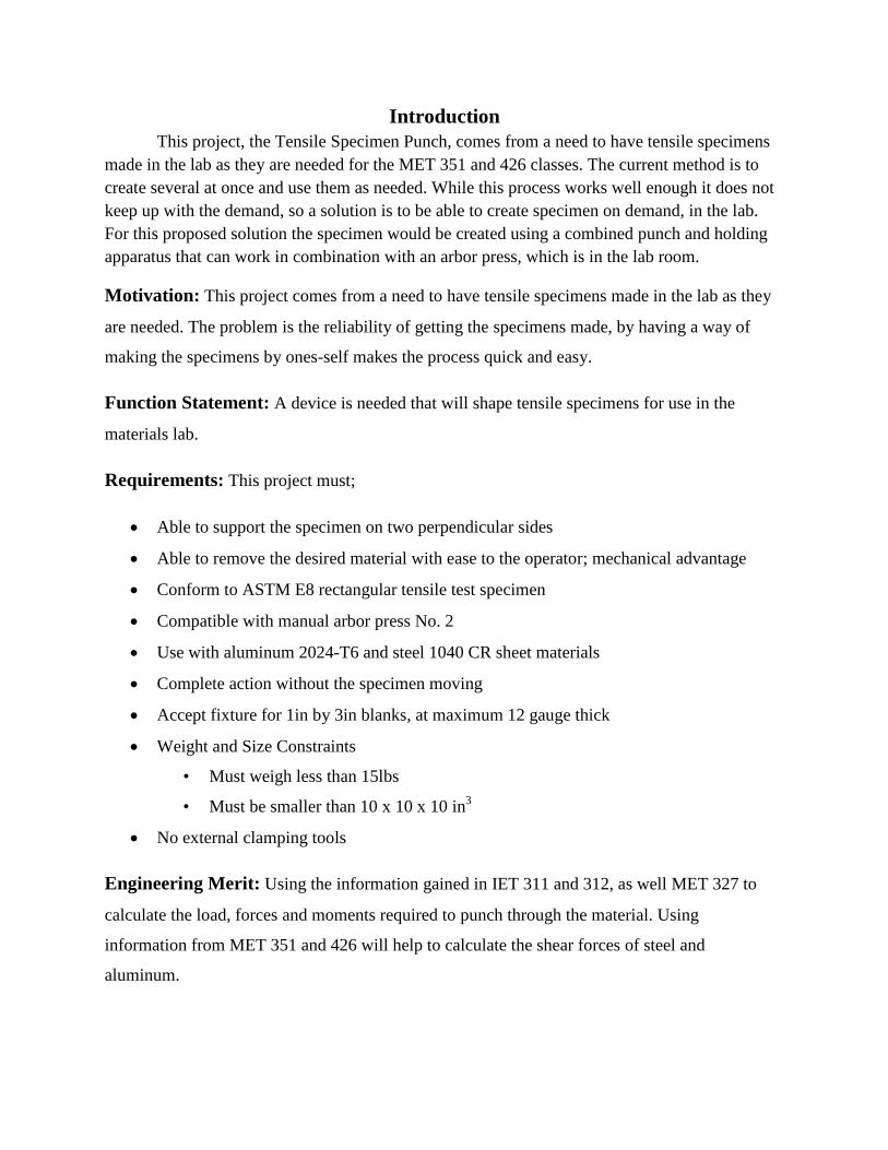
Introduction
This project, the Tensile Specimen Punch, comes from a need to have tensile specimens
made in the lab as they are needed for the MET 351 and 426 classes. The current method is to
create several at once and use them as needed. While this process works well enough it does not
keep up with the demand, so a solution is to be able to create specimen on demand, in the lab.
For this proposed solution the specimen would be created using a combined punch and holding
apparatus that can work in combination with an arbor press, which is in the lab room.
Motivation: This project comes from a need to have tensile specimens made in the lab as they
are needed. The problem is the reliability of getting the specimens made, by having a way of
making the specimens by ones-self makes the process quick and easy.
Function Statement: A device is needed that will shape tensile specimens for use in the
materials lab.
Requirements: This project must;
Able to support the specimen on two perpendicular sides
Able to remove the desired material with ease to the operator; mechanical advantage
Conform to ASTM E8 rectangular tensile test specimen
Compatible with manual arbor press No. 2
Use with aluminum 2024-T6 and steel 1040 CR sheet materials
Complete action without the specimen moving
Accept fixture for 1in by 3in blanks, at maximum 12 gauge thick
Weight and Size Constraints
• Must weigh less than 15lbs
• Must be smaller than 10 x 10 x 10 in3
No external clamping tools
Engineering Merit: Using the information gained in IET 311 and 312, as well MET 327 to
calculate the load, forces and moments required to punch through the material. Using
information from MET 351 and 426 will help to calculate the shear forces of steel and
aluminum.

Scope of Effort: This project includes the base, that holds the specimen in place, and the
punch, that will remove the material.
Success Criteria: this project will be complete when the base and punch can be mounted to the
arbor, the specimen can be supported on the base, and the punch can remove the desired
material.
Design and Analysis
Approach: The design of this project is to create a base that can hold a specimen, as well as
having the punch attached for convenience to remove the desired material. This base will be able
to be placed upon the arbor press, a specimen inserted, and material removed with ease and
convenience.
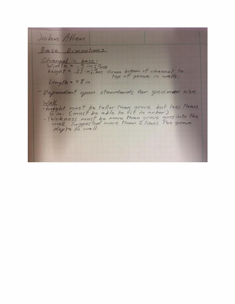
Design Description: For the base there will be two perpendicular walls that the specimen will
sit flush against, as well as a hole directly in line with the punch allowing the removed material
to fall away. There will also be a punch that is the desired shape for the removed section from the
specimen.
Benchmark: The arbor press being used is the PMW no. 2:

Performance Predictions: The desired performance of this device is to hold the specimen in
place as the punch removes material. The arbor press will reduce the 11*106 lb force for shear
down to 9.9*106 lb force applied by the operator.
Description of Analyses: The specimen requires a force of # lb to shear steal, which is the
stronger of the two materials used.
Scope of Testing and Evaluation: To test this device, it must operate with little to no
reaction motion in the specimen.
Analyses:
Design Issue:
• Making the walls geometry precise
• Hardening the punch
• Punch geometry
Calculated Parameters:
• The arbor press has to apply a force of at least # lb to shear steel.
• The operator has to apple a force of # lb to the handle. (This can be reduced by
making the handle longer)
Best Practices:
• Follow safety standers to make the device user friendly so the operator does not
hurt themselves.
Device:
• Parts: The base needs to have a channel that can fit the specimen in without
allowing the specimen to move. The side and the back need to have grooves that
will prevent the specimen from lifting. The rails need to guide the punch without
allowing it to move out of alignment.
• Shapes: The bottom of the base will be at minimum, as long as the length of a
normal specimen and as wide as the width of the specimen plus the punch. The
back will be the same length as the bottom, and the side will be as long as the
width of the bottom minus the thickness of the back. The height of the back and
side are not specified, as long as they can fit in the arbor press.

• Conformation: The back and side will be attached with screws to both the bottom
and each other, so the faces need to have the smallest deviation as possible.
Device Assembly: The bottom will be where everything is mounted. The back and
side will be attached with screws, both to the bottom and to themselves. The rails will
be attached on either side of the relief hole, with the punch put between the rails.
There will also be a way of attaching the structure to the foot of the arbor press, the
design will be decided later.
Technical Risk Analysis: The largest risk in this project will be harm to the operator,
in the form of cutting or smashing of the hand. This harm will occur if the operators
hand is caught under the punch, or caught between the punch and the arbor rack as
the arbor is being operated. It is also worth knotting that any harm done will be
minimal, due to the fact that the operator is also the one applying the force to the
arbor press, leading to a release of force when harm is initially applied.

Methods and Construction
Construction: The base was initially made, from aluminum provided by Dr. Johnson. Then the
die was then created out of steel provided by the machine shop here on campus. The punch was
next created out of S7 tool steel. The punch support was the last to be created out of the same
material as the die. All parts were created here on campus in the machine shop.
Description: This project comes from a need to have tensile specimens made in the lab as they
are needed for the MET 351 and 426 classes. The problem is the reliability of getting the
specimens made, by having a way of making the specimens by ones-self makes the process quick
and easy.
Drawing Tree and Drawing ID’s:
Manufacturing Issues: The main issues involved will be getting the optimal punch design and
creation of the punch. The facilities that are able to be used at this time do not have the
knowledge or the capability to produce the punch. Contacting an industry representative for this
kind of information will be the best course of action to take.
Tensile Specimen
Punch Assembly
Base Assembly
Base Punch Die
Punch
Support
Box

Testing Method
Introduction: The primary testing method will be the comparison of the calculated force to
shear with the actual force to shear when attempted.
Method/Approach: The method used will just be to test shearing in the structure. Once an
initial test has been completed then a force sensor will be used to find the force required to shear.
Test Procedure:
1. Place the structure in the arbor press, making sure it is square and lined up.
2. Insert the specimen into the structure, making sure it is in its proper place.
3. Lower the arbor press until it has made contact with the punch and the punch is lowered
to the specimen.
4. Apply force to the handle; continue shearing all the way through the specimen. Lift the
handle when completed.
5. Remove specimen, turn up-side-down from previous orientation, and reinsert into the
structure. Make sure the pre-punched section is away from the punch.
6. Repeat steps 3 and 4, after remove specimen from structure.
Deliverables:
Force testing will be completed using a force sensor attached to the handle as a force is
applied causing a shearing action. This force sensor must be able to register a force of at least
400 lb, which is the suggested max force that the specified arbor press can handle.
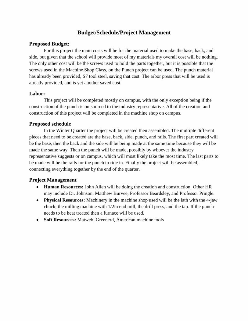
Budget/Schedule/Project Management
Proposed Budget:
For this project the main costs will be for the material used to make the base, back, and
side, but given that the school will provide most of my materials my overall cost will be nothing.
The only other cost will be the screws used to hold the parts together, but it is possible that the
screws used in the Machine Shop Class, on the Punch project can be used. The punch material
has already been provided, S7 tool steel, saving that cost. The arbor press that will be used is
already provided, and is yet another saved cost.
Labor:
This project will be completed mostly on campus, with the only exception being if the
construction of the punch is outsourced to the industry representative. All of the creation and
construction of this project will be completed in the machine shop on campus.
Proposed schedule
In the Winter Quarter the project will be created then assembled. The multiple different
pieces that need to be created are the base, back, side, punch, and rails. The first part created will
be the base, then the back and the side will be being made at the same time because they will be
made the same way. Then the punch will be made, possibly by whoever the industry
representative suggests or on campus, which will most likely take the most time. The last parts to
be made will be the rails for the punch to ride in. Finally the project will be assembled,
connecting everything together by the end of the quarter.
Project Management
Human Resources: John Allen will be doing the creation and construction. Other HR
may include Dr. Johnson, Matthew Burvee, Professor Beardsley, and Professor Pringle.
Physical Resources: Machinery in the machine shop used will be the lath with the 4-jaw
chuck, the milling machine with 1/2in end mill, the drill press, and the tap. If the punch
needs to be heat treated then a furnace will be used.
Soft Resources: Matweb, Greenerd, American machine tools

Discussion
Design Evolution / Performance Creep:
The design for this project is based off a drawing from Dr. Johnson. The design
sufficiently holds and supports the specimen while the material is being removed. The main
concern addressed with the design is to hold the specimen in place, without wobble, allowing for
the most accurate end result. There is another design/apparatus suggested by Matt Burvee similar
to a parallel clamp that would work as well. That apparatus was not chosen due to the a fact that
it would be more cost effective to simply buy the already made device instead of creating one
from scratch, making the initial design the more desirable path to take.
Project Risk analysis:
The greatest risk in this project is that the desired material is not removed. With the
design of this project the punch will be able to repeatedly remove material, leading to the desired
outcome. In such this project will work the way it is designed to.
Successful:
The most important design requirement is that the specimen is to stay in place without
moving while the material is removed. The specimen is supported in all directions, not allowing
it to move sideways, front to back, or up and down, also it be not able to spin, rotate, or rock in
any direction. These restrictions lead to the desired precise repeatable outcome.
Next phase:
This project will live its life in Lab room 127, where Dr. Johnson has his classes so it can
be easily accessed and used. It will be stored on one of the shelves in 127, where it can be used
for the MET 351 and 426 classes.

Conclusion
This project, the Tensile Specimen Punch, comes from a need to have tensile specimens
made in the lab as they are needed for the MET 351 and 426 classes. The current method is to
create several at once and use them as needed. While this process works well enough it does not
keep up with the demand, so a solution is to be able to create specimen on demand, in the lab.
For this proposed solution the specimen would be created using a combined punch and holding
apparatus that can work in combination with an arbor press, which is in the lab room. This
project will securely hold a specimen in place without letting it move as the punch removes the
desired material. Going off the design of this project the goal will be achieved with ease and
repeatability.

Appendix A- Analysis


Appendix B- Drawings
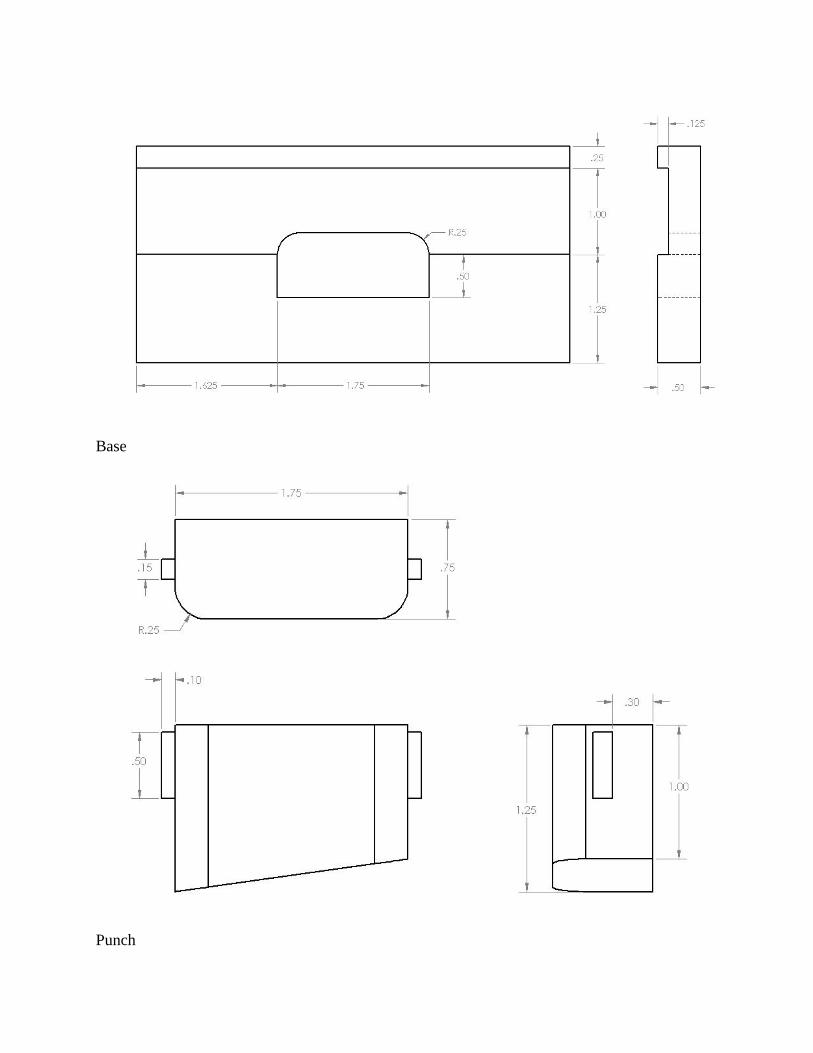
Base
Punch

Assembly

Appendix- C Parts List
Part Name Description
Base Machined from Aluminum
Punch Machined from Tool Steel
Die Machined from scrap Steel
Punch Support:
Back Machined from scrap Steel
Sides Machined from scrap Steel
Front Machined from scrap Steel
Screws Cut to length
Springs

Appendix- D Budget
Material Cost ($)
Aluminum 0, Provided by Dr. Johnson
Tool Steel 0, Provided by Dr. Johnson
Steel 0, Provided by Machine Shop
Screws 0, Provided by Machine Shop
Springs 0, Provided by Machine Shop
Time No idea what to charge for
my time.

Appendix- E Schedule
Description Time (hrs.) OCT NOV DEC JAN FEB MAR APR
Act. Est.
Proposal 30
Outline 3
Intro 7
Methods 10
Analysis 9
Discussion 8
Parts & Budget 15
Drawings 10
Schedule 5
Summary & Appx 5
subtotal: 102
Proposal Mods
Project Schedule 1
Project Part Inv. 2
Critical Design Review 2
subtotal: 5
Part Construction
Print Part Drawing 1 1
Get Material 2 2
Make Base Plate
Facing 1 1
Length 2 1
Chanel/Step 1.5 1
Punch Hole 2 1
Punch Mate Hole 1.5 1
Releif Hole 1 1
Screw Holes 0.5 0.5
Tap 1 0.5
Make Punch Box
Front
Face 0.5 1
Length 0.5 1
Height 1 1

Holes 0.5 0.5
Back/Support
Face 1 1
Lenfth 1 1
Height 1 1
Holes 2 0.5
Sides (2)
Facing 1 1
Length 1 1
Height 0.5 1
Holes 1 0.5
Tap 0.5 0.5
Make Punch Mate
Face 1 1
Length 1 1
Height 2 1
Punch Relief 0.5 0.5
End Radii 0.5 1
Screw Holes 0.5 0.5
Make Punch
Facing 1 1
Length 1 1
Height 1.5 1
Width 1 1
Radial Corners 1 2
Cuttes face 2
Get Screws 1 1
Get/Make Spring 0.25 1
subtotal: 37.25 36
Device Construct
Assemble Device 3 12
subtotal: 3 12
Device Evaluation
List Parameters 3
Design Test & Scope 3
Make Test Sheets 4

Plan Analysis 3
Instrument Device 2
Test Plan 2
Perform Evaluation 8
Update Website 5
subtotal: 30
Total hours: 149.5

Appendix- J Resume
John Allen
[email protected] • (509) 250-2857
Objectives
Work in the engineering field. Gain experience and knowledge from my pears.
Education
Central Washington University
2017 Mechanical Engineering
• ASME/SME member
Experience
Klickitat County Personnel Department | 115 S Golden Ave, Goldendale, WA 98620
Engineer’s Summer Assistant 6-20-2016 – 9-21-2016
• Equipment handler and operator
• Data collector
Fun Jumpers LLC | 416 Cherry Heights Rd, The Dalles, OR 97058
Equipment Operator 6-12-2008 – 9-15-2016
• Line Operator
• Equipment Handler
• Personnel Handling
Skills
• Time Management
• Hard Working
• Multitasking
• Personable
• Management
• Self-discipline