Tensile and shear element erosion in metal foams - steel … · 12 th International LS-DYNA Users...
9
12 th International LS-DYNA Users Conference Session # 1-1 Tensile and shear element erosion in metal foams Stefan Szyniszewski a , Brooks Smith b , Sanjay Arwade b , Jerome Hajjar c , Benjamin Schafer a a Dept. of Civil Eng., Johns Hopkins University, Baltimore, MD 21218 b Dept. of Civil and Env. Eng., University of Massachusetts, Amherst, MA 01003 c Dept. of Civil and Env. Eng., Northeastern University, Boston, MA 02115 Abstract The goal of this paper is to simulate fracture observed in tensile and shear tests of steel foam specimens. Deshpande-Fleck plasticity was employed for numerical modeling, and calibrated against compressive and tensile experiments. Steel foam has plastic yield stress, and can deform under compressive load beyond 60% engineering strain. Unlike in compression, steel foam fractures at a small strain in tension. Weak tensile behavior is captured with the element deletion. In order to enhance the realism of the simulated fracture patterns, yield stress, Young modulus, and failure strain were randomly varied between all elements. Unfortunately, default material erosion produced shear fracture patterns significantly different from the experiments. Thus, alternative element erosion was postulated, and it was based on the maximum principal strain. The proposed criterion was shown to give adequate agreement with the experimental results. Tensile and shear fracture modeling of steel foams may benefit from inclusion of spatial variability of material properties. The proposed principal strain based element erosion performed better than the principal stress fracture cut-off. 1. Introduction Foamed steel intentionally introduces internal voids in steel (Figure 1). A variety of manufacturing methods are used to introduce the voids from powder metallurgy and sintering of hollow spheres to gasification [1]. Steel foams are largely still under development, e.g. [2]; however steel foam sandwich panels have been utilized in a demonstration project as a parking garage slab [3] while mass production of aluminum foam sandwich panels already exists [4]. In general, metal foams have high effective bending stiffness and energy absorption. In addition, metal foams have improved thermal conductivity [5], enhanced fire resistance [6], better noise attenuation [1][7], and provide improved electromagnetic and radiation shielding [8][9] when compared with solid metals. The overall objective of this study is to simulate the triaxial behavior of steel foam, and to capture tensile and shear fracture. Whereas steel foams are good candidates for cores in steel sandwich panels, their potential for brittle fracture needs to be adequately addressed.
Transcript of Tensile and shear element erosion in metal foams - steel … · 12 th International LS-DYNA Users...

12th International LS-DYNA Users Conference Session #
1-1
Tensile and shear element erosion in metal foams Stefan Szyniszewskia, Brooks Smithb, Sanjay Arwadeb, Jerome Hajjarc, Benjamin
Schafera
a Dept. of Civil Eng., Johns Hopkins University, Baltimore, MD 21218 b Dept. of Civil and Env. Eng., University of Massachusetts, Amherst, MA 01003
c Dept. of Civil and Env. Eng., Northeastern University, Boston, MA 02115
Abstract The goal of this paper is to simulate fracture observed in tensile and shear tests of steel foam specimens. Deshpande-Fleck plasticity was employed for numerical modeling, and calibrated against compressive and tensile experiments. Steel foam has plastic yield stress, and can deform under compressive load beyond 60% engineering strain. Unlike in compression, steel foam fractures at a small strain in tension. Weak tensile behavior is captured with the element deletion. In order to enhance the realism of the simulated fracture patterns, yield stress, Young modulus, and failure strain were randomly varied between all elements. Unfortunately, default material erosion produced shear fracture patterns significantly different from the experiments. Thus, alternative element erosion was postulated, and it was based on the maximum principal strain. The proposed criterion was shown to give adequate agreement with the experimental results. Tensile and shear fracture modeling of steel foams may benefit from inclusion of spatial variability of material properties. The proposed principal strain based element erosion performed better than the principal stress fracture cut-off.
1. Introduction
Foamed steel intentionally introduces internal voids in steel (Figure 1). A variety of manufacturing methods are used to introduce the voids from powder metallurgy and sintering of hollow spheres to gasification [1]. Steel foams are largely still under development, e.g. [2]; however steel foam sandwich panels have been utilized in a demonstration project as a parking garage slab [3] while mass production of aluminum foam sandwich panels already exists [4]. In general, metal foams have high effective bending stiffness and energy absorption. In addition, metal foams have improved thermal conductivity [5], enhanced fire resistance [6], better noise attenuation [1][7], and provide improved electromagnetic and radiation shielding [8][9] when compared with solid metals. The overall objective of this study is to simulate the triaxial behavior of steel foam, and to capture tensile and shear fracture. Whereas steel foams are good candidates for cores in steel sandwich panels, their potential for brittle fracture needs to be adequately addressed.

Session # 12th International LS-DYNA Users Conference
1-2
Figure 1. Metal foam sandwich panel (left), steel foam (right)
2. Steel foam plasticity (MAT_154) Steel foam can undergo volume change during inelastic deformation (Poisson’s ratio not equal to 0.5) and the presence of rapid stiffening of the material after densification initiates at engineering strains around 0.65 (Figure 2). These two features mean that standard J-2 plasticity theory cannot be applied to model HS steel foams since the evolution of the yield surface depends not only of deviatoric stress invariant J2 but also the trace of the stress tensor I1. Miller [10], and Deshpande and Fleck [11] later introduced a generalized von Mises-Huber plasticity model that accounts for pressure dependence of the yield surface. This formulation is called ‘D-F’ plasticity throughout this paper. The model recognizes that strain energy of compressible materials depends on both deviatoric and volumetric deformations (see appendix of [12]). D-F plasticity uses the following definition of the equivalent stress [11,12]:
��� = 11 + �� 3 �� �� � + ������ (1)
where � = von Mises effective stress, ��= mean stress, and � is compressibility parameter
�� = 92 �1 − 2����1 + ��� (2)
Steel foam remains compressible after its yield and its large deformation Poisson ratio �� is typically less than 0.3, as opposed to solid steel, which is practically incompressible, and thus �� = 0.5. Increasing pressure will cause the metal foam to yield. Experimental plastic Poisson ratio determines �, which controls plastic compressibility of foam under applied pressure (Figure 3). The required Poisson coefficient is a ratio of true strains, and not engineering strains. D-F plasticity reproduces experimentally measured plastic. J2 plasticity assumes�� = 0.5.

12th International LS-DYNA Users Conference Session #
1-3
� �� = 0.10 � �� = 0.35 � �� = 0.65 final
initial
Figure 2. Uniaxial compression test for calibration of steel foam plasticity
�� = 0.0 (� = 2.12) �� = 0.4 (� = 0.8)
Figure 3. Plastic Poisson ratio controls the shape of D-F yield surface
0 0.2 0.4 0.6 0.8 1 1.2 1.4 1.6 1.8
0
10
20
30
40
50
-True plastic strain
-Tru
e st
ress
(M
Pa)
Compressive test #1
Material model curve-fit
Session # 12th International LS-DYNA Users Conference
1-4
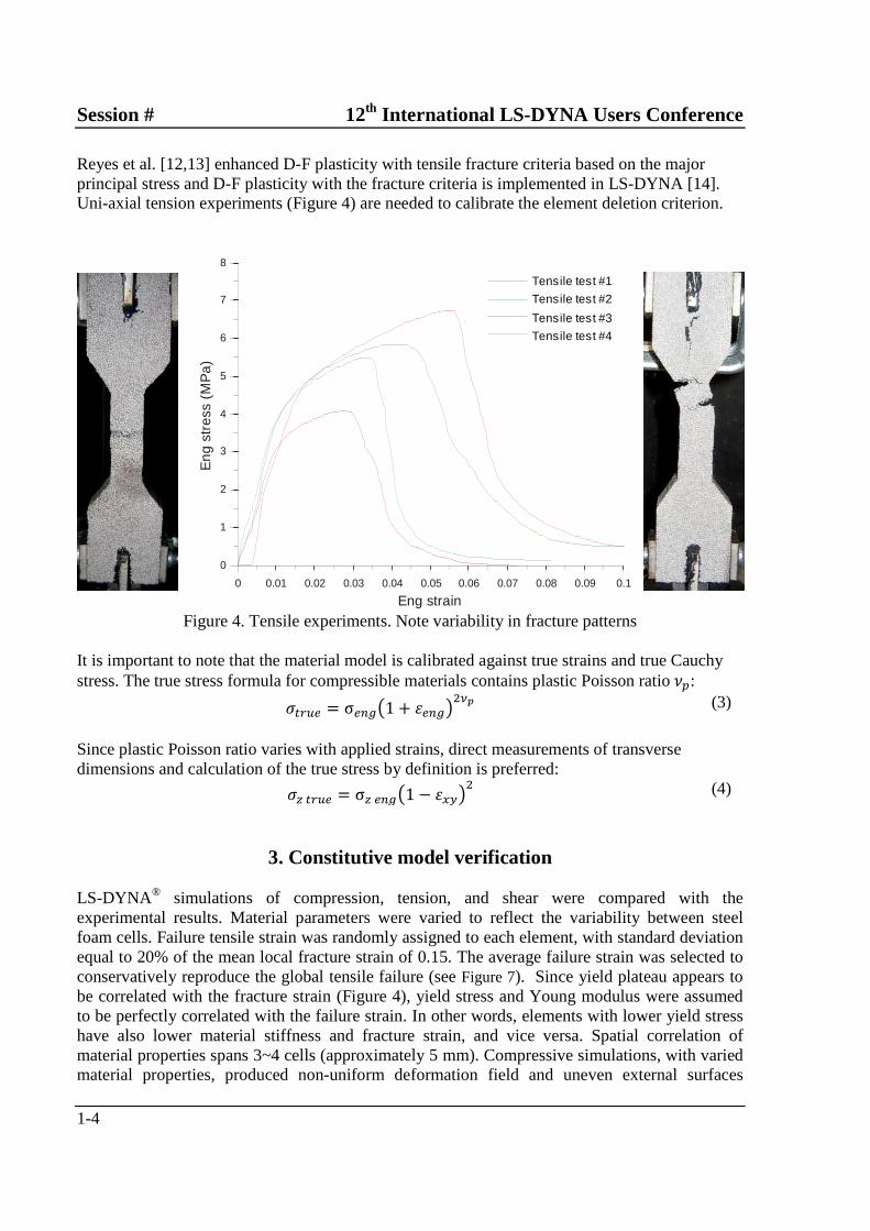
Reyes et al. [12,13] enhanced D-F plasticity with tensile fracture criteria based on the major principal stress and D-F plasticity with the fracture criteria is implemented in LS-DYNA [14]. Uni-axial tension experiments (Figure 4) are needed to calibrate the element deletion criterion.
Figure 4. Tensile experiments. Note variability in fracture patterns It is important to note that the material model is calibrated against true strains and true Cauchy stress. The true stress formula for compressible materials contains plastic Poisson ratio��: �� ! = σ ���1 + # ����$% (3)
Since plastic Poisson ratio varies with applied strains, direct measurements of transverse dimensions and calculation of the true stress by definition is preferred: �&� ! = σ& �� �1 − #'(�� (4)
3. Constitutive model verification LS-DYNA® simulations of compression, tension, and shear were compared with the experimental results. Material parameters were varied to reflect the variability between steel foam cells. Failure tensile strain was randomly assigned to each element, with standard deviation equal to 20% of the mean local fracture strain of 0.15. The average failure strain was selected to conservatively reproduce the global tensile failure (see Figure 7). Since yield plateau appears to be correlated with the fracture strain (Figure 4), yield stress and Young modulus were assumed to be perfectly correlated with the failure strain. In other words, elements with lower yield stress have also lower material stiffness and fracture strain, and vice versa. Spatial correlation of material properties spans 3~4 cells (approximately 5 mm). Compressive simulations, with varied material properties, produced non-uniform deformation field and uneven external surfaces
0 0.01 0.02 0.03 0.04 0.05 0.06 0.07 0.08 0.09 0.1
0
1
2
3
4
5
6
7
8
Eng strain
Eng
str
ess
(MP
a)
Tensile test #1
Tensile test #2
Tensile test #3
Tensile test #4

12th International LS-DYNA Users Conference Session #
1-5
(Figure 5). Locations of tensile fracture varied between numerical realizations (Figure 6). The simulations are consistent with the experimental tests (Figure 4). Both deterministic and random models are comparable in compression (Figure 7). However, the simulations, with varied material properties, encountered computational issues at compressive true strains larger than 0.6.
Figure 5. Sample realization with every element assigned a different material yield stress, Young modulus and fracture strain.
Figure 6. Numerical realizations of tensile fracture (stress state and element erosion)

Session # 12th International LS-DYNA Users Conference
1-6
Figure 7. Calibration (compression) and verification (tension) of numerical model against experiments
4. Principal strain based element erosion Shear modeling of steel foams is important for simulations of sandwich panels. Steel foam cores deform primarily in shear, and premature fracture may potentially affect the panel strength. D-F predicts higher shear yield than von Mises plasticity, but the shear yield is still lower than a uniaxial yield stress:
�)( = *1 + �3�3 �( = * 12�1 + ����( ≥ �,� = 1√3�( (5)
D-F gives �)( = 0.67�( for the investigated steel foam (with�� = 0.12), as opposed to von Mises prediction of0.58�(. Volumetric strain or volumetric stress is traditionally employed in an element erosion of compressible materials [14]. However, shear deformations do not produce any volumetric strain. Thus, volumetric strain is unable to predict shear failure. Reyes [12] proposed the use of the maximum principal stress in the element erosion criterion. The criterion is expressed in an equivalent energy form, in order to discount spurious dynamic stress oscillations. Experimental failure occurred along one of the fixtures, and distinct diagonal cracks were noticed only in a subset of tests (Figure 8A). Principal stress based erosion did not predict the fracture patterns observed in the shear experiments (Figure 8C). Simulations, with principal stress criterion, simultaneously delete elements at the diagonally opposite corners of the
-0.1 0 0.1 0.2 0.3 0.4 0.5 0.6 0.7 0.8 0.9
-10
0
10
20
30
40
50
Eng strain
Eng
str
ess
(MP
a)
Compressive simulation
Tensile random simulation
Compressive random simulationCompressive test #1
Compressive test #2
Compressive test #3
Tensile test #1Tensile test #2
Tensile test #3
Tensile test #4

12th International LS-DYNA Users Conference Session #
1-7
specimen (locations of principal tension). The element deletion pattern did not turn toward the centerline. Also, the force resistance did not decline after the failure initiation (Figure 9). A new element erosion criterion was proposed in order to capture the experimental fracture patterns. It is postulated that an element should be removed when its maximum principal strain exceeds the critical fracture strain. Values of failure strains varied between the elements. It is worth noting that the global failure was triggered by erosion of weaker elements with randomly assigned lower values of failure strain. The proposed element erosion was implemented with *MAT_ADD_EROSION keyword [14]. The improved numerical simulations reproduced the experimental fracture patterns (Figure 8B). Simulated cracks propagated along one of the fixture plates. The erosion path turned toward the centerline in approximately 30% of the random numerical realizations.
Experiment A
Proposed B
Default C Figure 8. Numerical simulation of the shear tests: A) experiment, B) Postulated material erosion based on the maximum principal strain, C) Element deletion based on the maximum principal stress (for comparison only). The proposed principal strain element deletion produces realistic erosion patters (Figure 8B). However, element deletion creates an opening between the portions of the fractured foam. In reality, the interlocking of the fractured surfaces still carries loads. The element deletion does not capture this interlocking. Thus, the simulated resistance drops shortly after the element erosion creates a void (Figure 9). Simulations with the strain based erosion accurately capture the shear crack patterns, but they may underestimate the softening and the dissipated energy.

Session # 12th International LS-DYNA Users Conference
1-8
Figure 9. Comparison of shear simulations with experiments
5. Conclusions Steel foam is emerging as a new structural material with intriguing properties: high stiffness-to-weight ratio, high energy absorption, and other advantages. Deshpande-Fleck plasticity was employed in numerical modeling of steel foam under compression, tension and shear. D-F plasticity accounts for foam’s compressibility, and it also reproduces experimental plastic Poisson ratio. Failure strain, yield stress and Young modulus were randomly varied to reproduce the spatial variability of the material properties in metal foams. In addition, a novel element erosion criterion was proposed. It postulates that an element should be deleted when its maximum principal strain exceeds the experimental tensile fracture strain. The proposed numerical models reproduced experimental tensile and shear behavior with adequate accuracy. Post-fracture softening in steel foams may require future studies.
References
[1] Ashby MF, Evans T, Fleck NA, Gibson LJ, Hutchinson JW, Wadley HNG. Metal Foams: A Design Guide. Butterworth-Heinemann; 2000.
[2] Kremer K, Liszkiewicz A, Adkins J. Development of Steel Foam Materials and Structures, US DOE and AISI final report DE-FC36-97ID13554. Newark, DE: Fraunhofer USA – Delaware Center for Manufacturing and Advanced Materials; 2004.
[3] Hipke T. Personal Communication 2011. [4] Banhart J, Seeliger H-W. Aluminium foam sandwich panels: Manufacture, metallurgy and applications.
Advanced Engineering Materials 2008;10:793–802. [5] Neugebauer R, Hipke T, Hohlfeld J, Thümmler R. Metal foam as a combination of lightweight engineering and
damping, 2005.
0 0.05 0.1 0.15 0.2 0.25
0
1
2
3
4
5
6
7
8
Eng shear strain
Eng
she
ar s
tres
s (M
Pa)
Simulation (principal strain based failure)
Simulation (principal stress based failure)
Shear test #1
Shear test #2
Shear test #3

12th International LS-DYNA Users Conference Session #
1-9
[6] Coquard R, Rochais D, Baillis D. Conductive and Radiative Heat Transfer in Ceramic and Metal Foams at Fire Temperatures - Contribution to the Special Issue “Materials in Fire” Guest Editor K. Ghazi Wakili 2010.
[7] Bao H-Q, Han B-K. Transmission loss of metallic foams for the local resonance. 3rd International Conference on Bioinformatics and Biomedical Engineering, iCBBE 2009, 2009.
[8] Losito O, Barletta D, Dimiccoli V. A wide-frequency model of metal foam for shielding applications. IEEE Transactions on Electromagnetic Compatibility 2010;52:75–81.
[9] Xu S, Bourham M, Rabiei A. A novel ultra-light structure for radiation shielding. Materials and Design 2010;31:2140–6.
[10] Miller RE. A continuum plasticity model for the constitutive and indentation behaviour of foamed metals. International Journal of Mechanical Sciences 2000;42:729–54.
[11] Deshpande VS, Fleck NA. Isotropic constitutive models for metallic foams. Journal of the Mechanics and Physics of Solids 2000;48:1253–83.
[12] Reyes A, Hopperstad OS, Berstad T, Hanssen AG, Langseth M. Constitutive modeling of aluminum foam including fracture and statistical variation of density. European Journal of Mechanics - A/Solids 2003;22:815–35.
[13] Hanssen AG, Hopperstad OS, Langseth M, Ilstad H. Validation of constitutive models applicable to aluminium foams. International Journal of Mechanical Sciences 2002;44:359–406.
[14] Hallquist J. LS-DYNA theory manual. Livermore, California: Lawrence Software Technology Corporation; 2006.