Tennessee Technological University - tntech.edu€¦2 | Page Student Learning Outcome 1:...
30
1 | Page Tennessee Technological University Institutional Effectiveness Department of Manufacturing and Engineering Technology Bachelor of Science in Engineering Technology (BSET) Academic Year : 2011-2012 Department/Unit: Manufacturing and Engineering Technology College: Engineering Submission date: February 28, 2013 Contact: Dr. Ahmed ElSawy I. Department Mission: The mission statement of the Department of Manufacturing and Engineering Technology, in concert with the College of Engineering’s (CoE) new strategic plan, is: “To graduate innovative Engineering Technologists and Applied Engineers who solve technological challenges to meet societal needs ” II. Program Goals and Student Outcomes: Program Goals The Program Goals for the Bachelor of Science in Engineering Technology, BSET, (formerly BS in Industrial technology, BSIT) used for the 2011-2012 years assessment cycle are as follows: Program Goal 1: The Department of Manufacturing and Engineering Technology will prepare graduates with the technical and managerial skills necessary for successful careers in the manufacturing and service industries. Program Goal 2: The Department of Manufacturing and Engineering Technology will prepare graduates to work as effective team members with commanding oral and written communication skills, as well as to advance in their careers and continue their professional development. Program Goal 3: The Department of Manufacturing and Engineering Technology will prepare graduates to exercise ethics in their profession and Department of Manufacturing and Industrial Technology to recognize the global impacts of their profession on society. Student Learning Outcomes Upon graduation, the students will be able to demonstrate:
Transcript of Tennessee Technological University - tntech.edu€¦2 | Page Student Learning Outcome 1:...
1 | P a g e
Tennessee Technological University
Institutional Effectiveness
Department of Manufacturing and Engineering Technology
Bachelor of Science in Engineering Technology (BSET)
Academic Year: 2011-2012 Department/Unit: Manufacturing and Engineering Technology College: Engineering Submission date: February 28, 2013 Contact: Dr. Ahmed ElSawy
I. Department Mission: The mission statement of the Department of Manufacturing and Engineering Technology, in concert with the College of Engineering’s (CoE) new strategic plan, is:
“To graduate innovative Engineering Technologists and Applied Engineers who solve technological challenges to meet societal needs”
II. Program Goals and Student Outcomes: Program Goals The Program Goals for the Bachelor of Science in Engineering Technology, BSET, (formerly BS in Industrial technology, BSIT) used for the 2011-2012 years assessment cycle are as follows:
Program Goal 1: The Department of Manufacturing and Engineering Technology will prepare graduates with the technical and managerial skills necessary for successful careers in the manufacturing and service industries. Program Goal 2: The Department of Manufacturing and Engineering Technology will prepare graduates to work as effective team members with commanding oral and written communication skills, as well as to advance in their careers and continue their professional development. Program Goal 3: The Department of Manufacturing and Engineering Technology will prepare graduates to exercise ethics in their profession and Department of Manufacturing and Industrial Technology to recognize the global impacts of their profession on society. Student Learning Outcomes Upon graduation, the students will be able to demonstrate:

2 | P a g e
Student Learning Outcome 1: Understanding of their manufacturing and engineering technology disciplines at a level above or comparable to their national peers.
Student Learning Outcome 2: Understanding of the theories and apply the principles and concepts of mathematics, science, chemistry at a level above or comparable to their national peers.
Student Learning Outcome 3: Understanding of the theories and apply the principles and concepts of management, production, and industrial safety management at a level above or comparable to their national peers.
Student Learning Outcome 4: Understanding of the quality control principles to the entire set of activities and operations within an enterprise at a level above or comparable to their national peers
Student Learning Outcome 5: Understanding of the skills and ability to work effectively in a team-based environment. With the continuing development of global sourcing and delivery of products, the Engineering Technologists and Applied Engineers must maintain an awareness of and appreciation for the wide variety of cultures and economic systems present in the world. Student Learning Outcome 6: Understanding of and a commitment to address professional and ethical responsibilities including a respect for diversity
III. Assessments
• Alumni Survey (sent out to graduates of TTU’s Engineering Technology program every six years intervals) – Program goals 1-3: The alumni survey contains questions directly related to the attainment of Program Educational Goals and Student Learning Outcomes. Written comments are also collected and coded as strength and weaknesses.
• ATMAE’s Certified Technology Manager (CTM) is online exam administered by the Department every semester for the senior students – Program Outcomes 1-3; Student learning outcomes 1-4.
• Senior Exit Interview Written Survey followed by oral discussion with the chairperson -Student Learning Outcomes 1-6: This exit interview is conducted every semester for graduating seniors.
• MET Industrial Advisory Board (twice a year) – Program Goals 1-3; Students Learning
Outcomes 1-6.
IV. Rationale for Outcomes and Assessments (Process of Data Analysis):
• Alumni Survey: conducted every six years – Program Goals 1-3; Student Leaning Outcomes 1-6. The alumni survey contains questions directly related to the attainment of Program Educational Goals and Student Learning Outcomes. Written comments are also collected and coded as strengths and weaknesses.

3 | P a g e
• ATMAE’s Certified Technology Manager (CTM) - Program Goals 1-3; Student
learning outcomes 1-4. The report of this exam is automatically generated and the department receives an excel file contain the analysis of the data obtained from the ATMAE Certification Exam administered for our students. The examination consists of varying numbers of questions from over 9 categories (Chemistry, English, Industrial Safety Management, Management, Math, Physics, Production, Psychology, and Quality Control). For comparison purposes, results from a composite group of over 1000 examinees from over 20 other organizations are provided. A minimum passing score of 95 out of 160 is currently required to qualify for certification. The best part about this exam it is an external exam from which the passing rate assesses the Program Goals 1-3 ranking of TTU’s graduates to the average national passing rate. Furthermore, the nine (9) categories assess the ranking of the Student Learning Outcomes to the national composite group.
• Senior Exit Interview Written Survey followed by oral discussion with the chairperson - Student Learning Outcomes 1-6: The exit interviews are conducted every semester and administered by the chairperson of the department to all graduating seniors. Specific questions relating to instruction, laboratory activities and student interests are noted. A careful examination of this information can help evaluate instruction in the department, determine the applicability of laboratory activities relating to the student learning outcomes, emphasis of lecture versus laboratory activities, and other important aspects in the daily operation of the department.
• MET Industrial Advisory Board (twice a year) – Program Goals 1-3; Students Learning Outcomes 1-6. Since the advisory board is a good cross section of industry represented by individual members of manufacturing, sales, engineering and design, it is a good sounding board for determining important information in the updating of the curriculum to represent modern technology. This modern technology can be transferred to student learning outcomes. As technology changes, new courses must be developed to reflect these modern concepts and changes in the program goals.
V. Results Alumni Survey Reviewing the results of the Alumni Survey, it is remarkable that the ratings received on all questions are fairly high overall, ranging from 3.8 to a high of 4.7, with an average of 4.25. The alumni survey indicates the high satisfaction among the graduates of the ET program and the ATMAE certification exam compare the TTU graduates to the national average graduates. This is an indicator that the education the alumni received while at TTU made them successful in the performance of their job duties and advances their careers. Some examples of the alumni responses are shown in the following figures:
i. One of the questions pertaining to Program Goal 1 was: Description of Duties which describes your present position. The reply to this question is shown in the following figure:

4 | P a g e
ii. One of the questions in the survey, we asked the alumni if the engineering technology curriculum is relevant to the job competencies of their industries. The response was as shown in the following figure. This supports the Program Goal 1.

5 | P a g e
Strongly agree
Strongly disagree
iii. In another question about how the Engineering Technology curriculum reflects current industrial
practices. The response of this question is shown in the following figure. This supports the Programs Goal 1 also.
Strongly Strongly agree disagree
iv. Another question requested from the alumni if the level of the Chemistry and Physics courses
are adequate for your position. The response is shown in the following figure. This response supports the Student Learning Outcome 2.
Strongly agree
Strongly disagree
v. Also, another question requesting from the alumni their opinion of the levels of Mathematics
courses are adequate for your position. The response is shown if the following figure. This response supports the Student Learning Outcome 2.

6 | P a g e
Strongly agree
Strongly disagree
In general, the alumni expressed their content of the education they received by the department and how this education prepared them for their jobs. Some Alumni Comments which needed some actions
• “Overall, the MET program did a s job of preparing me to be technically minded. The courses and faculty did provide opportunities to problem solve and work out solutions for various course requirements, at times with groups. Which provided a team work scenario and 'coworker relations" (Program Goals 1-3).
• Some other written comments stressed “the need of a program joined with an MBA with technical or engineering management would be a great program. Or a program that focused on production processes and a deeper study of theory and applications of manufacturing”. Others suggested the need of industrial automation for today’s manufacturing industry.
• Another comment noted the “importance of technical writing, verbal communications and team work”. Traditionally we have in the majority of the junior & senior years classes projects requiring the students to work in groups, writing technical reports and present the results of their finding orally before peers and faculty. An extra step was taken as shown below in the MET 4620-Senior Design class.
ATMAE’s Certified Technology Manager (CTM)
It is an online exam administered by the Department every semester for the graduating seniors – Program Outcomes 1-3; Student learning outcomes 1-4. Examples are presented in table 1 (fall 2011- 2012):
Table 1 - The Association of Technology, Management, and Applied Engineering
CONTENT AREA ANALYSIS FOR TENNESSEE TECHNOLOGICAL UNIVERSITY CONTENT AREAS Fall 2012 Spring 2012 Fall 2011 Passing Rate 100% 83.33% 65.00% National Passing Average 55.65% 55.57% 59.30%
1 Chemistry ANA - - - SANA - - - BNA
2 English ANA - - - SANA - - - BNA
3 Industrial Safety ANA - - ANA - - ANA - -

7 | P a g e
Management 4 Management ANA - - ANA - - - SANA -
5 Math ANA - - ANA - - - - BNA
6 Physics ANA - - SANA - ANA - -
7 Production ANA - - ANA - - ANA - -
8 Psychology ANA - - ANA - - ANA - -
9 Quality Control ANA - - - - BNA - SANA -
TOTAL 9 0 0 5 3 1 4 2 3
Above National Average = ANA Same As National Average = SANA Below National Average = BNA
Table 1 shows a continuous improvement in the passing rate from fall 2011 to 2012. The passing rate of TTU students is always above the national average. Also shows a considerable improvement in the 9-Content Areas (Student Learning Outcomes 1-4). The results of this exam are used by the department to assess and improve the 9-Content Areas as compared to the national peers.
Senior Exit Interview
Written survey followed by one-on-one oral with the chairperson for an informal confidential discussion of the MET Program strengths and weaknesses-Student Learning Outcomes 1-6: This exit interview is conducted every semester for graduating seniors. Specific questions relating to instruction, laboratory activities and student interests are noted. A careful examination of this information can help evaluate instruction in the department, determine the applicability of laboratory hands-on activities relating to the goals of the course, emphasis of lecture versus laboratory activities, and other important aspects in the daily operation of the department. This exit interview provides useful information regarding issues of students’ concerns. In general, the students were satisfied with the education they received I the department. Some concerns were about outdated equipment in the Electricity/Electronics lab. Also, a student said “I could have actually learned something in the electronics classes and PLC, but with the current professor it is difficult to almost impossible to learn anything that would be valuable, his English skills are very poor and when he is giving lecture, I wonder if he is intoxicated with the rambling and slurring of the English language that goes on during his lecture”. These negative comments were taken seriously and corrective actions were taken.
MET Industrial Advisory Board The MET Industrial Advisory Board meets twice a year (Program Goals 1-3; Students Learning Outcomes 1-6.) The MET Industrial Advisory Board is an external identity and consists of approximately 10-15 members, selected primarily from employers of our students and other related industries as well as the program alumni. Since the advisory board is a good cross section of industry represented by individual members of manufacturing, sales, engineering and design, it is a good sounding board for determining important information and feedback regarding upgrading of the curriculum to represent modern technology and accreditation matters (ATMAE and SACS). This board was very instrumental in changing the

8 | P a g e
department direction from Manufacturing and Industrial Technology to Manufacturing and Engineering Technology and changing the curriculum toward this goal. With the advice from this group, the curriculum was fine-tuned and we were selected to partner with Chattanooga State Community College to offer BS in Engineering Technology to VW employees and workforce in Chattanooga area. Appendix I & 3 shows the press release and the curriculum.
VI. Modifications and Continuous Improvement: Program Changes due to
Assessments
For Program Goals 1-3 and Student Learning Outcomes 1-5 In general, the data obtained from the previous assessment tools used to assess the BSET indicate that at a minimum, a level of Satisfactory has been attained for all program outcomes and educational objectives. However, some indicator showed some areas needed some changes or improvement during this time period. 1. The necessary actions were taken to change the program directions from BS in
Industrial Technology to BS in Engineering Technology. This change required adding some engineering science to the curriculum and creating a balance between the Why and the How. Within the 120 credit hours mandated by TBR, The actions taken were: 1) working with the Mathematics Department to combine Math 1910 and 1920 in on2 course MATH 1845-Technical Mathematics and eliminate the unnecessary subjects for the Engineering. 2) Adding Statics and Strength of Materials course to be a prerequisite for the Machine Elements course, 3) Reduce the number of credit hours in the MET 1100 course from 3 CH to 2 CH and eliminate the introduction to Engineering from the curriculum to save 1 CH. Use the Physics I + MATH 1845 as prerequisites for the MET 3403-Machine Elements and Physics II + MATH 1845 as prerequisites for the MET 3200. Also, the program requires the use of MATLAB in the BSET curriculum. The MIT Department's name has been officially approved by TBR and changed to MET on 11-14-2012.
2. Another action item was taken during the 2011-12. Several outdated lab equipment
were replaced and new experiments were adopted to support the student learning outcomes in the areas of electricity/electronics, PLC, Industrial Automation, reverse engineering and renewable energy. Also, a classroom will be renovated and turned to Mobile Learning Environment System Infrastructure (MoLESI) classroom to adopt new pedagogy and be able to deliver distance learning courses to VW academy in Chattanooga. The recent students’ exit interview showed students satisfaction and attested by spending longer hours after class periods in the labs.
3. Another action item was taken to improve the students learning outcomes. The
professor was sent to take a course in interpersonal communication in the English department. He was also was send to an education workshop to improve his teaching/pedagogy. The department is watching the students’ evaluation of this particular instructor to determine if there are improvements.
4. Another action item is underway. In the senior year the BSET will have two emphases:
1) Manufacturing Engineering Technology focusing on production processes and a deeper study of theory and applications of manufacturing and 2) Technology Management leading to MBA with technical or engineering management.

9 | P a g e
5. Another action was taken to motivate the students and improve their technical, written
and communication skills. For the first time a students’ group in the MET 4620-Senior Projects Class wrote a paper based on their senior research entitled “Solar and wind generation to power medical facilities in Haiti” this undergraduate research paper was presented and published at International Conference on Renewable Energies and Power Quality (ICREPQ’12), Santiago de Compostela (Spain), 28th to 30th March, 2012. This spring 2013 semester, another group of students repeated the same experience and wrote a paper entitled “Production of Biodiesel from WVO Using Small Scale Continuous Ultrasonic Processor” was accepted and will be presented and published
To close the assessment loops, the department developed a systematic way to feedback the assessment results into the curriculum. To achieve this goal at the course level, the department has developed a course-level assessment policy (Course Learning Outcomes 1-5). Following are the procedures and responsibilities of using assessment results for continuous improvement. Each course will be formally assessed after each semester and prior to the next schedule semester in which it will be taught (see Appendix V). These steps were taken in the example shown in item IV-1 to change the program direction to BSET.

10 | P a g e
APPENDIX I
TTU, VW AND CHATTANOOGA STATE PARTNER TO OFFER DEGREE, SUPPORT INDUSTRY
Posted by Karen Lykins - Thursday, June 09 2011 [email protected] Office of Communications & Marketing TTU President Bob Bell, Chattanooga State Community College president Jim Cantanzaro, Hans-Herbert Jagla, EVP of Human Resources for Volkswagen ChattanoogaTennessee Tech University, Volkswagen Chattanooga and Chattanooga State Community College have partnered to provide education, training and job placement efforts that will align with the unique needs of Volkswagen, their tier-one parts providers and the growing manufacturing industry in the state.
A workforce development system will provide a seamless articulation of education and training through Chattanooga State and Tennessee Tech University for students to obtain a Bachelor of Science degree in Industrial Technology.
Representatives from the Volkswagen Academy, Chattanooga State’s engineering technology division and TTU’s industrial technology department crafted an agreement that will support long-term sustainability in educating a qualified and skilled workforce critical for the emergence of the automotive industry and the manufacturing workforce needs of the greater Chattanooga economic region.
“We saw this as a great opportunity to demonstrate how higher education can be innovative and responsive to the needs of students and industry,” said TTU President Bob Bell. “We are excited about the collaboration with Volkswagen and Chattanooga State because it allows us all to align our focus with the state’s goals to increase higher education opportunities for students and expand support of workforce development.”
With training from the Volkswagen Academy, students who hold an A.A.S. degree in engineering technology from Chattanooga State can seamlessly transfer to a bachelor’s degree program from Tennessee Tech University.
“We are very pleased that Tennessee Tech and Chattanooga State are working together to create this much-needed degree program and that classes will be held in our Volkswagen Academy,” said Hans-Herbert Jagla, EVP of Human Resources for Volkswagen Chattanooga.
“We believe in offering education to our youth and in creating opportunities for growth. I believe that this program will set a milestone to help ensure the future of our region and Volkswagen,” Jagla said.
According to the Chattanooga State President Jim Catanzaro, “This is a natural extension of our training partnership with Volkswagen Chattanooga. Volkswagen and supplier employees as well as people from businesses in the area will be able to move up professionally based on two very targeted degrees, which blend business, engineering and technology.”
The skills and competencies essential to the Volkswagen workforce mandate a systematic re-evaluation of the curricula in engineering, manufacturing and industrial technology at both Chattanooga State and TTU.
Employees of Volkswagen Chattanooga will be among the first students accepted into the program; classes are set to begin Sept. 6 as part of the flex schedule. Flex schedule classes, also known as late start classes, begin two to three weeks after the traditional beginning of the semester in August.
The new initiative becomes official with a 2+2 agreement between Chattanooga State and Tennessee Tech University for a bachelor of science in industrial technology.
In a separate agreement, Chattanooga State students will also find an efficient transfer process to TTU and academic support from advisers at both schools as a result of a dual admissions program now in place.
For further details about the program call Chattanooga State at (423) 697-4434 or log on to www.chattanoogastate.edu/engineering. To contact Tennessee Tech University call (931) 372-3238 or (931) 473-8022, or visit the website at www.tntech.edu/mit.

11 | P a g e
APPENDIX II
TTU, VW AND CHATTANOOGA STATE 2+2 CURRICULUM
Tennessee Technological University/Chattanooga State Community College Articulation/Transfer Agreement/B.S. Engineering Technology
Chattanooga State Community College A.A.S. Engineering Technology - Mechanical Engineering Technology
1Course substituted for PHYS 1030 for transferability 3Course substitution from MD 274 to NE 228 2DD 114 is a pre-requisite 4Prescribed elective; may choose any from approved list General Education Bridge Courses
ENGL 10205 Composition II 3 hrs
Literature Elective5 Choose from: ENGL 2130–American Lit.; ENGL 2230–British Lit.; ENGL 2330–World Lit. 3 hrs
HIST 2010 or 20205 American History I or II 3 hrs 5These courses can be taken online in the Regents Online Degree Program (RODP)
Tennessee Technological University B.S. EngineeringTechnology
Junior Senior Course Code Course Name Hours Course Code Course Name Hours BMGT 3510 Management & Organizational
Behavior 3 ACCT 3720 Accounting for Non-Business Majors 3
ECON 3610 Business Statistics I 3 BUS Elec. (ECON 2020)6
Principles of Macroeconomics 3
HU/FA Humanities/Fine Arts Elective 3 DS 3520 Operation Management 3 MIT 2000 Occupational Safety 2 HIST 2010 or20 American History I or II 3 MIT 3060 CNC Machining Practices 3 MIT 4200 Industrial Electronics 3 MIT 3130 Maintenance Technology I 3 MIT 42107 PLC & Process Control 3 MIT 3403 Applied Machine Elements 3 MIT 42208 Industrial Automation 3 MIT 3700 Manufacturing Cost Estimating 2 MIT 4310 Plant Layout & Matls Handling 3 MIT 3710 Methods Design and Work Meas. 2 MIT 4610 Engineering Technology Seminar 1 MIT 3730 Quality Assurance 2 MIT4620 Senior Project 3 PHYS 2020 Algebra-based Physics II 4 PSY 2010 General Psychology 3
Total 30 Total 31
6Prescribed elective; may choose any from approved list 7 Prescribed elective; may choose any from approved list 8 Prescribed elective; may choose any from approved list
Freshman Sophomore Course Code Course Name Hours Course Code Course Name Hours ENGL 1010 Composition I 3 MATH 1910 Calculus I 4 ENGL 2710 Technical Reports 3 EE 284 Electrical Tech for Mech. Engr. 3 ET 115 Computers for Engr. Technology 3 HU/FA Humanities/Fine Arts Elective 3 MATH 1710 Pre-Calculus I 3 MD 134 Statics & Strengths of Materials I 3 MATH 1720 Pre-Calculus II 4 MD 242 Statics & Strengths of Materials II 3 PHYS 20101 Non-Calculus Based Physics 4 MD 226 Fluid Power 3 CHEM 1010 Introduction to Chemistry 4 MD 264 Thermo Dynamics 3 DD 1242 CAD Engineering Drawing II 3 NE 2283 Fundamentals of Metallurgy 3 MD 184 Manufacturing Processes 3 Social/Beh. Sci.
(EC 212)4 Principles of Economics I (Micro Economics)
3
MD 254 Elements of Material Science 3 Tech Elec. CAD 3-D Elective (CATIA) 3 Total 33 Total 31

12 | P a g e
APPENDIX III
European Association for the Development of Renewable Energies, Environment and Power Quality (EA4EPQ)
International Conference on Renewable Energies and Power Quality (ICREPQ’12) Santiago de Compostela (Spain), 28th to 30th March, 2012
Solar and wind generation to power medical facilities in Haiti
Students: William Hafner-Burton and Peter Nelson
Faculty Advisor: Dr. Ahmed ElSawy
1 Department of Manufacturing and Industrial Technology Tennessee Technological University
College of Engineering – 920 N Peachtree Ave Cookeville, 38501 Tennessee (United States) Phone/, e-mail: [email protected]; [email protected];
[email protected] Abstract. The main objective of this senior design project was to design, manufacture, and test a lightweight portable power generator utilizing wind and solar power. The intent of this system is to provide electricity to power the medical equipment in a small clinic in Haiti. Haiti is suffering from recent natural disasters and in urgent need of support from the United States and other countries. So far, about 100 million dollars in aid has been poured into Haiti as well as medical supplies/equipment and manpower including engineers, nurses, doctors, etc. With such a power generator system, Haitians will be able to economically supplement the power needed to run their clinic’s equipment. Haiti is a prime spot for solar and wind generation, using its over 3000 hours of sunlight and trade winds to produce optimal amounts of green energy. This richness of natural resources was the main motivation behind developing this economical system, building it to set up a strong basis for green renewable energy into their economy, monitoring its setup, and learning from the findings. Powering a small clinic is just a small step into making Haiti a self-sufficient country in the area of power generation. The details of this wind and sun renewable energy system are described and discussed in this undergraduate research paper. Key Words Wind power generation, solar power generation, Haiti medical facilities, and renewable energy 1. Introduction Haiti has a large amount of solar and wind power generation potential. Haiti needs this potential to help it grow out of its economical hardship status as well as improve its living environment. A wind turbine/solar system is needed that incorporates these characteristics: economical and low maintenance cost, safe in the event of a transient excess of winds, lightweight and portable, and able to generate energy in low winds and survive high winds. This study aims to show the economic feasibility of installing small wind/solar power generators for medical facilities throughout Haiti. After researching the type of wind turbine that should be used, the horizontal turbine had an easier time starting up because wind from any direction could be used to propel the blades as

13 | P a g e
opposed to a vertical turbine where the blades need to be facing the wind in order to generate power. The horizontal turbine does not need any specific wind direction to generate power. Also, direct power generation is used instead of a gearing system to reduce inertia, friction, and improve efficiency. An alternating current generator is utilized in view of the fact that it has the highest voltage output in lower winds. A large battery bank powers the medical equipment and lights while the wind turbine and solar cells recharge the batteries. A charging circuit controls the power going into the batteries to charge them properly, preventing the batteries from overcharging. The circuit also regulates the load on the wind turbine which puts strain on the blades slowing them down in high winds; the higher the wind speed, the larger the load. Therefore, more power is generated while the blades are seemingly spinning at the same speed. 2. Materials and Methods A. Winds survey for the region of Haiti An analysis of wind currents and wind seasonality along eight years was carried out by weatherreports.com. The projected monthly averages of the winds were obtained from Port-Au-Prince, Haiti [2]. B. Solar Survey for the region of Haiti An analysis of path of the sun was done by haitipassivecooling.tumblr.com in Santiago de Cuba which is in close proximity to Port-au-Prince, Haiti. An ecotect analysis was used to gather this information. C. Choice of wind power generator A low maintenance, high efficiency, high voltage output generator would be needed to produce enough energy to charge the battery bank. The generator would also need to be safe and reliable. D. Economic feasibility of the project The wind turbine and solar panels will need to be inexpensive to produce and small enough to economically ship to Haiti in a standard 45’ dry container. E. Design of the turbine 2D and 3D computer software was used to design and engineer the wind turbine. Programs like Autodesk Inventor, SolidWorks, AutoCAD, MasterCam, and Pro-E are acceptable programs to complete the design phase of the project. F. Materials to use All the materials used to build the system are corrosion resistant, strong, light-weight, and non-magnetic. Also, the materials used have good machinability and formability properties. G. Manufacturing the turbine
14 | P a g e
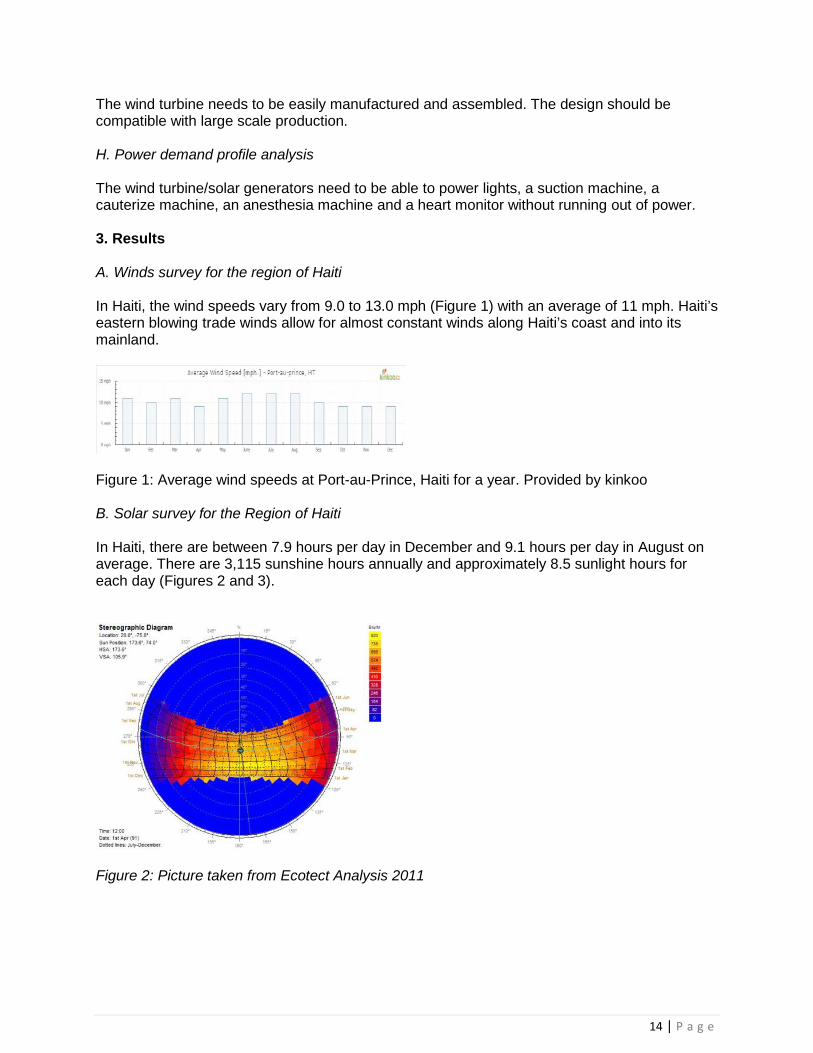
The wind turbine needs to be easily manufactured and assembled. The design should be compatible with large scale production. H. Power demand profile analysis The wind turbine/solar generators need to be able to power lights, a suction machine, a cauterize machine, an anesthesia machine and a heart monitor without running out of power. 3. Results A. Winds survey for the region of Haiti In Haiti, the wind speeds vary from 9.0 to 13.0 mph (Figure 1) with an average of 11 mph. Haiti’s eastern blowing trade winds allow for almost constant winds along Haiti’s coast and into its mainland.
Figure 1: Average wind speeds at Port-au-Prince, Haiti for a year. Provided by kinkoo
B. Solar survey for the Region of Haiti In Haiti, there are between 7.9 hours per day in December and 9.1 hours per day in August on average. There are 3,115 sunshine hours annually and approximately 8.5 sunlight hours for each day (Figures 2 and 3).
Figure 2: Picture taken from Ecotect Analysis 2011

15 | P a g e
Figure 3: graph of sunrise, sunset, and time of light in port-au-prince Haiti. C. Design of the turbine The first step in designing a wind turbine is deciding to use a horizontal-axis wind turbine (HAWT) or a vertical-axis wind turbine (VAWT). After comparing the two types of turbines, the HAWT was selected. The VAWT runs into problems with support, bearings, fatigue, startup, and speed control. The HAWT is safer, produces better energy, does not suffer from a hard startup and is easier to manufacture. A vertical design was conceptualized, and then engineered into AutoCAD and Autodesk Inventor. Three, four foot blades were designed using a wing shape to reduce wind resistance. Three blades are chosen over two blades because two blades lead to “blade chatter,” a vibration that puts wear and tear on the whole machine. Three bladed machines do not have this issue. With three blades positioned 120 degrees apart, the direct imbalance that two-blade turbines are susceptible to is avoided. The three blades also run quieter because they move slower and are more stabilized, reducing vibrations. Deciding whether to choose a direct-drive or a gear-driven generator ended in picking out a direct-drive generator. Gear-driven generators face too many disadvantages; its gear, belts, and pulleys increase energy loss. The machine is also made more complex by adding gears, meaning more parts to buy, maintain, and replace. A direct-drive generator provides the most energy out of the wind in the simplest way. A custom- made three phase AC (alternating current) generator was designed for this purpose. Magnetic bearings were designed to reduce the amount of friction on the blade, helping the turbine to reduce startup time.

16 | P a g e
Figure 4: 3D cad drawing of the wind turbine D. Materials to use Aluminum (7075, used in aircraft blades) is used for the blades, generator and bearings; stainless steel is used for the axis. Coils are encased in a fiberglass resin to prevent them from being scratched. E. Choice of wind power generator The power generator is a three phase AC power generator. A three phase power generator achieves its high conductor efficiency and low safety risk by splitting up the total voltage into its three lesser parts. It converts the wind mechanical power into a set of three AC electric currents, one from each coil (or winding) of the generator. The windings are arranged such that the currents vary sinusoidally at the same frequency but with the peaks and troughs of their wave forms offset to provide three complementary currents with a phase separation of one-third cycle (120° or 2π⁄3 radians). F. Manufacturing the turbine Each part is designed in Autodesk Inventor and transferred to MasterCam which produces G&M CNC (Computer Numerical Controlled) codes. These codes are used to produce each part to tolerance and specification as defined in the CNC code. Neodymium magnetic bearings are used to support and center the stator. These bearings are used in conjunction with centering thrust bearings to improve the magnetic bearing life expectancy. The stator coils are incased in fiberglass to protect them from being scratched, preventing a short. The solar panels are obtained from a third party.

17 | P a g e
Each CNC code is run through a wood dry run, and a final testing with aluminum. Each piece is processed through a series of finishing machining processes to smooth the edges and take out any rough spots in the product. The coils are wound sixty-four times with 15AWG Copper armature wire. This was done nine times. Then the coils are paired together and incased in fiberglass resin. 24, N42 grade neodymium magnets are used on the AC generator. Two magnet plates are CNCed out of aluminum with 12 place holders for magnets. The magnets are epoxy bonded into the place holders on each plate. The magnetic bearings are made using four N42 grade circular neodymium magnets. The advantages of magnetic bearings are that they are high speed, do not need lubrication, have no resistance, very low vibration, and experience minimal wear. They are centered onto the axis using a thrust bearing. A safety cage is built around the wind turbine to keep bodily harm to a minimum. The cage is made out of steel angle iron. G. Economic feasibility of the project This system is characterized as being environmentally friendly and economical. It does not produce any pollutants and it is feasible because it would be less expensive to manufacture and install the wind turbines and solar generators than to import fuels from overseas and run gas or diesel powered generators. The life of a wind turbine with magnetic bearings is 10-15 years. This allows for the power usage to pay for itself over this time period. With the use of magnetic bearings there is very little maintenance required. For a full cost estimate on parts and manufacturing refer to table 1. The total cost of materials and parts needed to build the wind turbine/solar power system is about $ 24,057.00. Also this cost will go down if the turbine is mass produced due to the fact that the manufacturer will be buying the materials in bulk reducing their cost. The main costs are in the batteries, shipping container, and solar panels. In comparison, the cost of running a gasoline generator to power the same facility for the same duration of time as the wind turbines is estimated to be 2.5 million dollars in a worst case scenario (the gasoline in Haiti is around $6.14 a gallon.). This as compared to $30,000 ($6,000 in maintenance costs over 15 years) for buying and building the wind/solar generators is much smaller. Table 1 - Description, quantity, unit cost and total cost of all materials. Line # Description Qty. Unit Cost Total
1
Multipurpose Aluminum (Alloy 6061) .032" Thick, 24" X 48"
9 $63.55 $571.95
2
Multipurpose Aluminum (Alloy 6061) .063" Thick, 48" X 48"
3 $162.26 $486.78
3
Architectural Aluminum Tube (Alloy 6063) Square, 3/4" X 3/4", 1/8" Wall, 6' Length
6 $12.30 $73.80
4 Architectural Aluminum (Alloy 12 $4.58 $54.96

18 | P a g e
6063) 1/4" Thick, 1/4" Width, 8' Length
5
Multipurpose Aluminum (Alloy 6061) .125" Thick, 12" X 12"
3 $29.05 $87.15
6
Precision-Cast Multipurpose Aluminum (MIC 6) 1/2" Thick, 12" X 12"
6 $63.99 $383.94
7
Multipurpose Aluminum (Alloy 6061) Tube 1-1/2" OD, 1" ID, .250" Wall Thickness, 1' Length
3 $18.09 $54.27
8
Perma-Lube Steel Ball Bearing - ABEC-1 Double Sealed, NO. R16 for 1" Shaft Dia, 2" OD
6 $22.29 $133.74
9
Multipurpose Stainless Steel (Type 304/304L) 1" Dia, 6' Length
3 $75.67 $227.01
10
Vinyl-Coated Polyester Fabric 0.022" Thick, 61" Width, White, 10' Length
3 $48.20 $144.60
11 1.5 In Angle Iron 24' 18 $31.00 $558.00
12 Surrette S530 6V 400 AH Wet Battery 30 $389.37 $11,681.10
13 Solar Panel Array - 800W w/ 2.5 kVA Inverter
1 $6,999.99 $6,999.99
14 Standard 45' Shipping Container 1 $2,000.00 $2,000.00
15 Miscellaneous Cabling Supplies 1 $400.00 $400.00
16 Miscellaneous Painting Supplies 1 $200.00 $200.00
17 Magnets-N42 Neodymium 1 $576 $576
*Note Medical Equipment is not Included $24,057.29
H. Power generation profile analysis

19 | P a g e
A typical medical service station is comprised of the following: a light source, an intermittent suction machine, a cauterizing (electrosurgical generator), an anesthesia machine, and a heart monitor. For more information on the power usage for the medical equipment refer to Table 2. Table 2:- Medical equipment with their respective power usages Equipment Volt
(AC) Amperes
Watts
Cree Toffer 120 0.18 44 GE Intermittent Suction Pump
120 3 360
Digital Electrosurgical Generator
120 1.14 250
Datex Ohmeda S/5 ADU
120 15 1800
Dash3000 120 2 75 -Total- 120 21.32 252
9
It is determined that we have a 2.52 kw draw on average per day (assuming a 100% duty cycle per day). Using simple conversions a 3.15 kVA UPS (Uninterruptable Power Supply) for a 24-hr period equates to a 6,000 AH battery bank at 12 volts. An industrial grade battery rated at a service life of 10-15 years was selected and chosen for the application. Due to these batteries being 6V and 400 AH a series of 15 batteries is connected in parallel with a twin bank of batteries which will satisfy the requirements for our design. For power generation three six foot diameter by eight foot tall wind turbines and supplemental solar arrays allow for a continuous operating time of eight hours with a max run time of 32 hours. After this time the battery bank and power generation systems will be depleted. The power output range of a wind turbine is 96-288 watts according to the following equation and average wind speeds.
𝑃 = 0.00508 ∗ (𝐷 ∗ 𝐻) ∗𝑊3 ∗ (𝑆 ∗ 𝑇) Where: P = Power (Watts) D = Diameter (Feet) H = Height W = Windspeed (MPH) S = Stator Efficiency T = Wing Efficiency A solar panel array amounting to 800W of daytime power output supplements the remaining gap and inefficiencies to allow for a full battery charge in a worst case scenario. All turbine parts, batteries, and solar panels will be transported in a 45 foot dry shipping container. The container can be shipped by boat, and transported on a truck bed over land to the medical facility. The storage container can then be used to house the batteries and the wind turbines can be mounted on top of the container along with the solar panels. This allows for minimum setup and takedown time and reduced the length of electrical wire needed from each power generator. Having this mobile capability allows for the medical facility to become mobile in cases of economic emergency. The facility can be moved with its power generators to areas that need its help. Once the truck has reached its destination the turbines and solar panels are setup on top of the container and the batteries are hooked up to the medical facilities power grid. The cargo

20 | P a g e
container also protects the wind turbine and solar panels from damage caused by hurricanes. When a hurricane or large storm is coming into the path of the medical facility the turbine and solar panels can be disassembled and placed into the container until the danger has passed. This helps to keep repair and replacement costs to a minimum. 4. Discussions Wind and solar energy would be the best option for Haiti at the moment. With 80% of Haiti being powered by domestic biomass fuel and some Hydro-electric sources it is facing a severe energy crisis [5]. Factors leading to problems are server deforestation and land degradation due to burning wood and coal for power. With the use of Solar and wind power Haiti could supply its power usages while reducing greenhouse gasses and restoring its forests. The objective of this project is to start on a smaller scale and just focus on the smaller medical facilities. Upon success of this project, it is possible to build a larger scale units to serve larger buildings. 5. Conclusions This study shows that it is possible to design and build a cutting edge green power generator using solar and wind power that can sustain a small medical facility in Haiti without the aid of any external power sources. Wind turbines and solar panels also offer a low maintenance power source that does not rely on non-renewable resources. Haiti has the potential to become an example of how renewable energy generation can change a country from fossil foil energy to green renewable energy. 6. Acknowledgements The authors would like to express sincere gratitude to Robert Nelson (BS/MS in Electrical Engineering) and Tana Hafner-Burton (BS in Nursing, MS in Healthcare Administration/ MS in Nursing C) for their help during the course of this study. Also, they grateful to all the help and assistance received from the Department of Manufacturing and Industrial Technology at Tennessee Technological University’ faculty, staff and fellow students. 7. References [1] Weather Reports and Forecasts for Haiti. http://www.weatherreports.com/Haiti/Port-
au-prince.
[2] Haiti Passive-Cooling January 7th 2011. http://haitipassivecooling.tumblr.com
[3] Port-Au-Prince, Haiti Climate Guide to the Average Weather & Temperatures with Graphs Elucidating Sunshine and Rainfall Data & Information about Wind Speeds & Humidity: July 22nd 2011 http://www.climatetemp.info/haiti [4]http://www.allaboutcircuits.com/vol_2/chpt_10/2.html [5] Ministry for Public Works, Transportation and Communications Bureau of Mines and Energy Electricity of Haiti, November 2006 http://www.bme.gouv.ht/energie/National_Energy_Plan_Haiti_Revised20_12_2006VM.pdf [6]http://www.conserve-energy-future.com/VerticalAxisWindTurbines.php

21 | P a g e
[7] Harrison, Robert, E. Hau, and Herman Snel. Large Wind Turbines: Design and Economics. Chichester: Wiley, 2000. Print. [8] Fox, Brendan. Wind Power Integration: Connection and System Operational Aspects. London: Institution of Engineering and Technology, 2007. Print. [9] Khaligh, Alireza, and Omer C. Onar. Energy Harvesting: Solar, Wind, and Ocean Energy Conversion Systems. Boca Raton: CRC, 2010. Print. [10] Woofenden, Ian. Wind Power for Dummies. Hoboken, NJ: Wiley Pub., 2009. Print. [11] Lubosny, Zbigniew. Wind Turbine Operation in Electric Power Systems: Advanced Modeling. Berlin: Springer, 2003. Print. [12] Manwell, J. F., J. G. McGowan, and Anthony L. Rogers. Wind Energy Explained: Theory, Design and Application. Chichester, U.K.: Wiley, 2009. Print. [13] Ragheb, Adam, and Magdi Ragheb. Wind Turbine Gearbox Technologies. International Nuclear and Renewable Energy Conference, 21 Mar. 2010. Web. 14 Sept.2011. https://netfiles.uiuc.edu/mragheb/www/Wind%20Power%20Gearbox%20Technologies.pdf.

22 | P a g e
APENDIX IV
International Conference on Renewable Energies and Power Quality (ICREPQ’13)
Bilbao (Spain), 20th to 22th March, 2013 Renewable Energy and Power Quality Journal (RE&PQJ)
ISSN 2172-038 X, No.11, March 2013
Production of Biodiesel from WVO Using Small Scale Continuous Ultrasonic Processor
Justin Wood1, Jared Slayton1, Seth Parrott1, Chinyere Mbachu2, and Ahmed ElSawy3 1Undergraduate Students, 2Ph.D Candidate, and 3Professor and Faculty Advisor
Department of Manufacturing and Engineering Technology, College of Engineering, Tennessee Technological University, Cookeville, Tennessee 38505-0001, USA
Phone # 0019313723238/Fax # 0019313723813, emails:1 [email protected], [email protected], [email protected],
[email protected] Abstract. There is a need in the USA to decrease dependency on fossil fuels. One alternative fuel that has gained much popularity in the past few years is biodiesel. Biodiesel can be produced using vegetable oil, waste vegetable oil (WVO), animal fat and yellow grease as raw materials. However, the process of converting a batch of WVO into usable biodiesel is time consuming, requires a human operator to run the system, and necessitates the performance of a chemical titration for each batch of biodiesel produced. In the first phase of this project, the processor was designed and built by the senior design students utilizing a programmable logic controller (PLC) in conjunction with pumps, valves, temperature sensors, etc. to completely handle the production of biodiesel with minimum operator interaction. This was the first step toward continuous flow processor and the elimination of the titration process. In the second phase of this project, the students integrated a small Hielscher Ultrasound continuous processing unit to the automated system. This paper presents the newly developed system and demonstrates the design aspects of the automated biodiesel production processor using a PLC and ultrasonication (continuous processing) as well as how the chemical titration procedure for each batch is eliminated. Keywords Biodiesel, Waste Vegetable Oil, Alternative Energy, Programmable Logic Controllers, Ultrasonication. 1. Introduction
With our desire to recycle and reuse solid waste, many people are looking for alternative ways to power vehicles and equipment using biofuel. One alternative fuel for diesel engines is biodiesel. The primary ingredient, waste vegetable oil (WVO), is available and inexpensive. However, the current processors available to produce batch biodiesel are time consuming. They require an operator to run and monitor the system, and necessitate a chemical titration procedure for each batch to be produced. In order to reduce the processing time, a more advanced system is needed. Therefore, the main objective of this project is to explore potential alternatives to the current biodiesel production methods, thus contributing to biodiesel commercialization. This main objective of this project is to develop a small scale continuous biodiesel process through the reduction of the operator interaction time, eliminating the titration process, moving the fluid throughout the system using solenoid valves and

23 | P a g e
PLC, use of ultrasonic reactor and presenting the end user with biodiesel upon completion of a full cycle. 2. Objectives
The ultimate goal of this project is to significantly increase the production capacity and product quality while reducing cost and human interaction. Therefore, this project is divided into two phases:
a. In the first phase [1], an automated continuous flow system that limits the operator interaction to depositing waste vegetable oil into the processor. The system should automatically take care of moving fluids throughout the system, all chemical reactions, draining of waste glycerol byproduct, and upon completion of a full cycle the system should present the operator with finished biodiesel that meets ASTM standards.
b. In the second phase, a small Hielscher industrial ultrasonic processor UIP500- 500W continuous biodiesel processor was integrated to the system. This technology creates nano-sized vacuum bubbles (i.e. cavitation) that help to overcome the cohesion and adhesion of the liquid it is mixing [2]. This introduction of cavitation to the reaction process is intended to reduce the processing time from ~ 1-4 hours needed in batch processing to less than ~ 30 seconds. Also, it reduces separation time from ~10 hours, down to ~1 hour.
3. Biodiesel Chemistry Biodiesel has several advantages such as: 1) being biodegradable, 2) being non-toxic, 3) having low emissions of carbon monoxide, 4) having a relatively high flash point (150° C), which makes it less volatile and safer to transport handle than petro-diesel, and 5) it has a good lubricating properties that can reduce engine wear and extend engine life [3]. Transesterification is the most common way to produce biodiesel. It is a catalyzed chemical reaction involving vegetable oil and an alcohol to yield fatty acid alkyl esters (i.e., biodiesel) and glycerol (Fig. 1).
Fig. 1 - A schematic representation of the transesterification of triglycerides (vegetable oil) with methanol to produce fatty acid methyl esters (biodiesel) (6) The Triglycerides are the main component of vegetable oil. It consists of three long chain fatty acids esterified to a glycerol backbone. When the triglycerides react with methanol, the three fatty acid chains are released from the glycerol skeleton and combine with the alcohol to produce fatty acid methyl esters (biodiesel) and glycerol as the by-product. R1, R2, and R3 represent Alkyl groups present in the WVO. The catalyst is NaOH (lye). In general, a large excess of methanol is used to shift the equilibrium far to the right (Fig.1). 4. Automated Biodiesel Processor Description

24 | P a g e
a. power generation Elimination of the Titration Process
In order to fully automate the process, the first step is eliminating the titration process which is needed before transesterification. This is because each batch of oil has a slightly different composition. The titration process consists of taking a small sample of WVO, and mixing it with lye, water, Phenolphthalein solution and alcohol in order to determine the pH level of a sample from each batch of oil and determining the correct lye to methanol ratio that is required for a particular batch. The process itself is not that difficult, but it does require careful measurement and operator knowledge of the process. To eliminate this procedure, a certain volume of WVO, a given volume of CH_3OH (methanol) and a given weight of NaOH (lye) are combined to produce sodium methoxide which will be used for the transesterification reaction. To obtain the needed amounts, a 25% the oil volume of methanol was used, and for lye 6.25 grams/liter of oil was used. Typically when an operator performs the titration process on a batch, the batch requires between six and seven grams of lye per liter of oil [4]. If fully reacted using 6.7 gallons of methanol and a potassium hydroxide catalyst, 55 gallons of WVO will produce 4.3 gallons of glycerin and 57 gallons of pure biodiesel. The Transesterification process chosen for this project consists of three steps to eliminate the titration from the process. It is based on the fact that most oils have a similar composition and therefore standard amounts of chemicals per volume of oil can be used (Fig. 1). Additionally, this method has the benefit of more completely reacting the oil with the sodium methoxide and therefore producing more biodiesel than other methods. When the oil reacts all at once it will reach an equilibrium stage at which point the reaction completely stops, even though more glycerin could be removed from the oil. Reacting the oil in two steps restarts the reaction at the second stage, allowing more glycerin to be split out of the waste vegetable oil. However, a drawback to this method is an increase in processing time. For this project this is acceptable as the length of the process is not a critical factor.
b. Biodiesel Processor
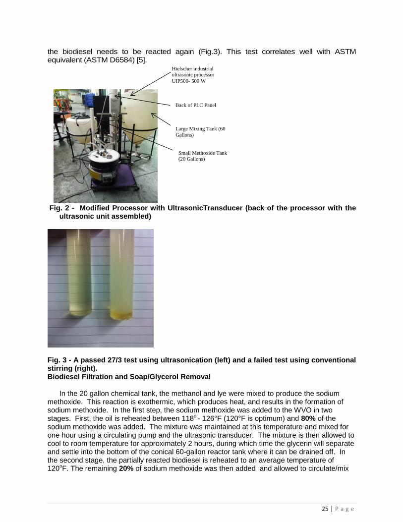
Fig. 2 illustrates the backside of the automated biodiesel processor. Before the actual reaction begins, it is important to preheat the WVO to reduce the viscosity and evaporate any water existing in the oil from cooking. The next step is to pre-filter the WVO in order to remove any food particles remaining in the oil so that the oil is clean and ready for the chemical reactions. To achieve this step, the WVO was poured through a series of progressively finer filtering screens. The finest filtering screen should be around 50 to 75 microns. After the pre-filtering stage, the oil is ready to be added to the 60 gallon tank for processing. Ultrasonic Transducer for Mixing WVO Mixing WVO is a lengthy process as we have found from prior research. The use of a mixing aid was needed to alleviate some of this time and make a more continuous process. The Hielscher industrial ultrasonic processor UIP500- 500 W was used for this project. The ultrasonic transducer uses cavitation or nano-sized vacuum bubbles that locally produce high temperatures and extreme pressures when the cavity implodes on itself. This creates jets of liquid that help to overcome the cohesion and adhesion of the WVO and sodium methoxide. This aids in the transesterification and allows for a better and more thorough reaction. Reaction rates can be examined by using a 27/3 test. This test shows how thorough the methanol and WVO have reacted with each other. It is done by mixing 3 parts biodiesel and 27 parts methanol. When mixed together the solution should have a single phase clear look. This signifies a pass. However, if the solution is cloudy and has more than one phase
25 | P a g e
the biodiesel needs to be reacted again (Fig.3). This test correlates well with ASTM equivalent (ASTM D6584) [5].
Fig. 2 - Modified Processor with UltrasonicTransducer (back of the processor with the
ultrasonic unit assembled)
Fig. 3 - A passed 27/3 test using ultrasonication (left) and a failed test using conventional stirring (right). Biodiesel Filtration and Soap/Glycerol Removal
In the 20 gallon chemical tank, the methanol and lye were mixed to produce the sodium methoxide. This reaction is exothermic, which produces heat, and results in the formation of sodium methoxide. In the first step, the sodium methoxide was added to the WVO in two stages. First, the oil is reheated between 118o - 126°F (120°F is optimum) and 80% of the sodium methoxide was added. The mixture was maintained at this temperature and mixed for one hour using a circulating pump and the ultrasonic transducer. The mixture is then allowed to cool to room temperature for approximately 2 hours, during which time the glycerin will separate and settle into the bottom of the conical 60-gallon reactor tank where it can be drained off. In the second stage, the partially reacted biodiesel is reheated to an average temperature of 120oF. The remaining 20% of sodium methoxide was then added and allowed to circulate/mix
Hielscher industrial ultrasonic processor UIP500- 500 W
Large Mixing Tank (60 Gallons)
Small Methoxide Tank (20 Gallons)
Back of PLC Panel

26 | P a g e
for another hour, and then is cooled for another 12 hours before draining any final glycerin that formed. The final step in the biodiesel process is to remove any soap, water, methanol, and other contaminants from biodiesel that were inadvertently created during the processing. Traditionally, a wet wash system is used for this process. It requires several wash cycles with water, and each cycle requires 12+ hours of settling/separation time. Then, it is also common practice to test the pH of the resulting biodiesel, and add an acid, such as vinegar, as necessary to balance the biodiesel’s pH level. Then the contaminated water must be properly disposed of, adding cost and time to the process. In this project, a drywash tower was designed specifically for this purpose. Initially the cost is greater, but the return on investment will be much higher because biodiesel can be produced faster and the end product will be of higher quality. Using a dry wash system with ion exchange media keeps us from having to balance the biodiesel pH by adding in an acid. In this project, a two-step dry wash process with Purolite® PD 206 filtering media [6] was planned. Before removing biodiesel from the 60-gallon reactor, it must be, or very close to, room temperature. This is because the higher temperatures can damage the filtering media and accelerate the degradation of the PVC pipe. The biodiesel was pumped through the tower at a rate of 7 gallons per hour. It was planned to have two dry wash filtration towers in order to ensure that the maximum amounts of contaminants are removed in a shorter period of time. From the towers, the biodiesel is pumped into a holding air tight and sealed tank, where it is ready to use in virtually any diesel engine.
c. Programmable Logic Controller Programming
The last step involved is writing a PLC program to control the two phase process and incorporate the drywash towers. The current biodiesel processor uses an Allen Bradley 503 PLC controller. The AB-503 PLC controller was selected because it is currently widely used in industry. It has multiple inputs and output capabilities and is easy to program (Fig. 3). In addition, the PLC will allow the operator to add a vast array of items to the process, such as flow meters, temperature gauges, timers, solenoid valves, and pumps quite easily. The processor works on an input/output basis for each action to occur. Once an input signal/signals are received (a given temperature, elapsed time, etc.) the controller sends an output signal (begin mixing, turn heater on, etc.). The PLC controller has 16 inputs (I:0 – I:15) and 16 outputs on two output cards (O2:0 – O2:7 and O3:0-O3:7) (Fig. 4). There are three buttons on the PLC panel; a green start button, a red stop button, and a black reset button. The red stop button can be pressed at any time to stop the processor. The reset button can also be used to stop the program, and it must be pressed after the stop button is pressed in order to reset the counters in the program. Fig. 3 – Illustrates the 503 Allen Bradley controller Inputs I:1/0 Thermostat I:1/1 Fluid Level Sensor 1 (Bottom of Small Tank) I:1/2 Fluid Level Sensor 2 (Top of Large Tank) I:1/3 Fluid Level Sensor 3 (Bottom of Large Tank) I:1/4 Stop Button (Red) I:1/5 Start Button (Green, bottom button) (NOTE: Press to start 1st and 2nd phase.) I:1/6 Reset Button (Black, Middle button) (NOTE: Press and release to stop processor.)
27 | P a g e
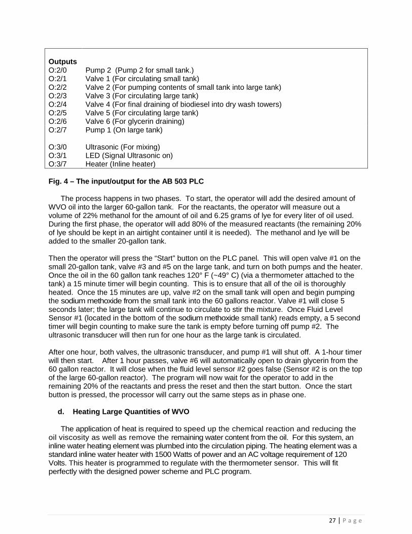
Outputs
O:2/0 Pump 2 (Pump 2 for small tank.) O:2/1 Valve 1 (For circulating small tank) O:2/2 Valve 2 (For pumping contents of small tank into large tank) O:2/3 Valve 3 (For circulating large tank) O:2/4 Valve 4 (For final draining of biodiesel into dry wash towers) O:2/5 Valve 5 (For circulating large tank) O:2/6 Valve 6 (For glycerin draining) O:2/7 O:3/0 O:3/1 O:3/7
Pump 1 (On large tank) Ultrasonic (For mixing) LED (Signal Ultrasonic on) Heater (Inline heater)
Fig. 4 – The input/output for the AB 503 PLC
The process happens in two phases. To start, the operator will add the desired amount of WVO oil into the larger 60-gallon tank. For the reactants, the operator will measure out a volume of 22% methanol for the amount of oil and 6.25 grams of lye for every liter of oil used. During the first phase, the operator will add 80% of the measured reactants (the remaining 20% of lye should be kept in an airtight container until it is needed). The methanol and lye will be added to the smaller 20-gallon tank. Then the operator will press the “Start” button on the PLC panel. This will open valve #1 on the small 20-gallon tank, valve #3 and #5 on the large tank, and turn on both pumps and the heater. Once the oil in the 60 gallon tank reaches 120° F (~49° C) (via a thermometer attached to the tank) a 15 minute timer will begin counting. This is to ensure that all of the oil is thoroughly heated. Once the 15 minutes are up, valve #2 on the small tank will open and begin pumping the sodium methoxide from the small tank into the 60 gallons reactor. Valve #1 will close 5 seconds later; the large tank will continue to circulate to stir the mixture. Once Fluid Level Sensor #1 (located in the bottom of the sodium methoxide small tank) reads empty, a 5 second timer will begin counting to make sure the tank is empty before turning off pump #2. The ultrasonic transducer will then run for one hour as the large tank is circulated. After one hour, both valves, the ultrasonic transducer, and pump #1 will shut off. A 1-hour timer will then start. After 1 hour passes, valve #6 will automatically open to drain glycerin from the 60 gallon reactor. It will close when the fluid level sensor #2 goes false (Sensor #2 is on the top of the large 60-gallon reactor). The program will now wait for the operator to add in the remaining 20% of the reactants and press the reset and then the start button. Once the start button is pressed, the processor will carry out the same steps as in phase one.
d. Heating Large Quantities of WVO
The application of heat is required to speed up the chemical reaction and reducing the oil viscosity as well as remove the remaining water content from the oil. For this system, an inline water heating element was plumbed into the circulation piping. The heating element was a standard inline water heater with 1500 Watts of power and an AC voltage requirement of 120 Volts. This heater is programmed to regulate with the thermometer sensor. This will fit perfectly with the designed power scheme and PLC program.

28 | P a g e
Conclusions
The result of the first phase of the senior project work is an automated processor that is capable of producing biodiesel with very limited operator interaction. For the system operators, a set of complete work instructions have been written to go along with the processor. The produced biodiesel was analyzed by the chemistry department and we believe it does meet the ASTM standards. It was used successfully in running an AMICO diesel engine AD 186FE.
The second phase results are a greatly reduced reaction time of approximately 1 hour using ultrasonication compared with 4 hours by using traditional means. Also, the settling period has been reduced from 12 hours to less than 2. Small batches were titrated and reacted by traditional means for comparison and 27/3 tests were performed on both these and the ultrasonified fuel. The use of sonochemistry provided B100 of even greater quality with more yield quantities than all previous tests. Acknowledgements This project was funded by the Department Manufacturing and Engineering Technology, The College of Engineering and the Graduate College at Tennessee Technological University. The authors would to acknowledge the contributions of the previous team members: Colt Jackson, John Manier, Karl Nye, Stephen Cole, Stephen Frazier, Caleb Goss, and Justin Wood. Furthermore, would like to acknowledge the efforts of Brent Moore, for working long hours on this project and leading the efforts of his group composed of Will Enicks, Kris Leeper, and Stephen Tischart. Moreover, we would like to thank Van Eric Short of the ECE Department for his help in programming the PLC. Finally, we would like also to thank Mr. Barry Allison and Mrs. Pauline Reyna for proof reading this manuscript. Bibliography [1] A. ElSawy, G. Graham, and M. Baswell, “Automation of Biodiesel Processor from Waste
Vegetable Oil using Programmable Logic Controller”, 2012 ASEE annual conference, Paper AC 2012-3263, St. Antonio, Texas, June 2012.
[2] http://www.hielscher.com/ultrasonics/sonochem_01.htm [3] http://www.eia.doe.gov/oiaf/analysispaper/biodiesel/index.html [4] Y. Zhang, M.A. Dube, D.D. McLean, M. Kates, “Biodiesel production from waste cooking
oil: 1. Process design and technological assessment”, Elsevier, Bioresource Technology 89 (2003) 1–16.
[5] http://utahbiodieselsupply.com/qualitytests. php [6] Purolite is a registered trademark of The Purolite Company, 2010. For more information see
http://purolite.com/RelId/33637/ISvars/default/Home.htm.

29 | P a g e
APPENDIX V
Assessment process for Quality Improvement
To close the assessment loops the department newly developed a systematic way to feedback the assessment results into the curriculum. To achieve this goal at the course level, the department has developed a course-level assessment policy (Course Learning Outcomes 1-5). Following are the procedures and responsibilities of using assessment results for continuous improvement. Each course will be formally assessed after each semester and prior to the next schedule semester in which it will be taught.
Each time a course is offered, the faculty member shall:
1. Prepare a course syllabus listing department, course number and title, course description, prerequisites, text(s), learning outcomes and their relationship to program goals, topics, class/laboratory schedule, and date of preparation and forward to the department chair;
2. Conduct and review student evaluation of the course to help find areas for course improvement as well as student service satisfaction improvement;
3. Evaluate students' knowledge of prerequisite material; 4. Assess students' performance in relation to learning outcomes; 5. Evaluate the state of the equipment in its laboratory; and 6. Revise the course by using the above feedback and forward course revisions,
recommendations for equipment updates and evaluation of prerequisites through department chair to the curriculum committee.
The chair will be requested to:
1. Collect and compile all prerequisite/laboratory material forms submitted by faculty; 2. Schedule curriculum committee meetings; 3. Conduct and compile stakeholder surveys; 4. Schedule industrial advisory committee meetings; 5. Forward Industrial Advisory Committee comments; and 6. Make recommendations to the curriculum committee.
The curriculum committee shall meet to:
1. Review any prerequisite/laboratory material forms submitted by faculty and recommend changes required to bring the curriculum into compliance;
2. Compile and rank order a list of laboratory improvements; 3. Confirm the accuracy of the course matrix; 4. Check capstone review forms to reflect compliance with guidelines; 5. Make recommendations to create/change courses to reflect reasonable external
stakeholders recommendations (supplied by the chair); and 6. Ensure the assessment feedback loops have been closed; and document their efforts.

30 | P a g e
Figure 1 – Continuous Improvement Diagram
This policy provides for the ability for the feedback of Program Goals and Students Learning Outcomes assessment results to the curriculum. The department feedback loop is formalized by three reports that make up the department continuous improvement policy:
1. Course-level Assessment and Continuous Improvement Report. 2. Program Goals Assessment and Continuous Improvement Report. 3. Student Learning Outcomes Assessment and Continuous Improvement
Report.
This policy forms the basis for the department documentation policy for tracking and documenting continuous improvement through the closure of the assessment loop. The course-level assessment and continuous improvement report is the first step document. This document is now completed subsequent to each semester in which a course is taught.