Tender Documents for Design, Supply, Installation, Testing ...
318
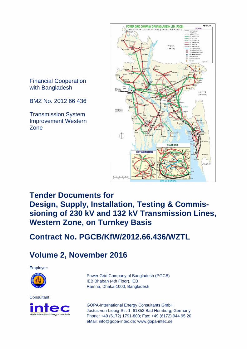
Financial Cooperation with Bangladesh BMZ No. 2012 66 436 Transmission System Improvement Western Zone Tender Documents for Design, Supply, Installation, Testing & Commis- sioning of 230 kV and 132 kV Transmission Lines, Western Zone, on Turnkey Basis Contract No. PGCB/KfW/2012.66.436/WZTL Volume 2, November 2016 Employer: Power Grid Company of Bangladesh (PGCB) IEB Bhaban (4th Floor), IEB Ramna, Dhaka-1000, Bangladesh Consultant: GOPA-International Energy Consultants GmbH Justus-von-Liebig-Str. 1, 61352 Bad Homburg, Germany Phone: +49 (6172) 1791-800; Fax: +49 (6172) 944 95 20 eMail: [email protected]; www.gopa-intec.de
Transcript of Tender Documents for Design, Supply, Installation, Testing ...
Financial Cooperationwith Bangladesh
BMZ No. 2012 66 436
Transmission SystemImprovement WesternZone
Tender Documents forDesign, Supply, Installation, Testing & Commis-sioning of 230 kV and 132 kV Transmission Lines,Western Zone, on Turnkey Basis
Contract No. PGCB/KfW/2012.66.436/WZTL
Volume 2, November 2016
Employer:
Power Grid Company of Bangladesh (PGCB)
IEB Bhaban (4th Floor), IEB
Ramna, Dhaka-1000, Bangladesh
Consultant:
GOPA-International Energy Consultants GmbH
Justus-von-Liebig-Str. 1, 61352 Bad Homburg, Germany
Phone: +49 (6172) 1791-800; Fax: +49 (6172) 944 95 20
eMail: [email protected]; www.gopa-intec.de

Bangladesh: Tender Documents for 230 kV and 132 kV Transmission Lines, Western Zone
Contract No. PGCB/KfW/2012.66.436/WZTLBGD 1800 WZTL vol 2 2016 11 16.docx
Contents of the Tender Documents
Volume 1
Section I. Instructions to Bidders (ITB)
Section II. Bid Data Sheet (BDS)
Section III. Evaluation and Qualification Criteria
Section IV. Bidding Forms
Section V. Eligible Countries
Section VI. Employer's Requirements
Section VII. General Conditions of Contract (GCC)
Section VIII. Special Conditions of Contract (PCC)
Section IX. Contract Forms
Volume 2
Scope of Works
Technical Specifications
Drawings forming Part of the Specification
Volume 3
Schedule A: Introduction & Preamble to the Price & Technical Schedules
Schedule B: Bid Prices & Schedules
Schedule C: Bar Chart Program of Key Activities-Delivery & Completion Time Schedule
Schedule D: Manufacturers, Places of Manufacture and Testing
Schedule E: Technical Particulars and Guarantees
Schedule F: Proposed Subcontractors

Bangladesh: Tender Documents for 230 kV and 132 kV Transmission Lines, Western Zone
Contract No. PGCB/KfW/2012.66.436/WZTLBGD 1800 WZTL vol 2 2016 11 16.docx
Table of Contents Page
SCOPE OF WORKS 1-1
1. Scope of Works and General Information 1-1
1.1 General 1-1
1.2 Extent of Supply 1-1
1.3 Details of Transmission Line Routes and Terrain 1-4
1.4 Location Details and Terminal Points 1-4
1.5 Estimated and Final Quantities 1-4
1.6 Modifications 1-5
1.7 Terminal Points 1-5
1.8 Programme of Work 1-5
Annex 1-1: Scope and Extent of Definite Works 1-6
Annex 1-2: Terminal Points 1-7
TECHNICAL SPECIFICATIONS 1-1
2. Site Particulars 2-1
2.1 General 2-1
2.2 Location 2-1
2.3 Climatic Conditions 2-1
Annex 2-1: Locations 2-2
Annex 2-2: Climatic Conditions 2-3
3. Quality Assurance 3-1
3.1 General 3-1
3.2 Quality Assurance Program 3-1
3.3 Quality Plan 3-2
3.4 Equivalent Standards 3-2
3.5 Quality Control 3-2
3.5.1 Inspection and Testing 3-2
3.5.2 Type, Sample and Routine Tests 3-3
3.5.3 Certificate of Conformity 3-3
3.6 Non-Conforming Products 3-3
3.7 Monitoring of Quality Assurance Arrangements 3-3
3.8 Suppliers and Subcontractors 3-3
3.9 Method Statements 3-4
Annex 3-1: Notification and Hold Points 3-5
Annex 3-2: Reference Standards 3-5
Annex 3-3: Certificate of Conformity 3-5
Annex 3-4: Engineering Documents to be submitted by the Contractor 3-6
Annex 3-5: Field Quality Plan for Transmission Lines 3-7
Annex 3-6: Acceptance Criteria and Permissible Limits for Cement 3-15
Annex 3-7: Acceptance Criteria and Permissible Limits for Reinforcement Steel 3-16
Annex 3-8: Acceptance Criteria and Permissible Limits for Coarse Aggregate 3-17
Annex 3-9: Acceptance Criteria and Permissible Limits for Fine Aggregate 3-18
Annex 3-10: Acceptance Criteria and Permissible Limits for Concrete Work 3-19
Annex 3-11: Approximate Positions of Towers 3-1

Bangladesh: Tender Documents for 230 kV and 132 kV Transmission Lines, Western Zone
Contract No. PGCB/KfW/2012.66.436/WZTLBGD 1800 WZTL vol 2 2016 11 16.docx
Table of Contents Page
4. Design Particulars 4-1
4.1 Philosophy of Design 4-1
4.2 Units of Measurement 4-1
4.3 Document Submission 4-2
4.4 Design Calculations 4-2
4.5 Drawings 4-2
4.5.1 General Requirements 4-2
4.5.2 Computer Generated Drawings/Designs 4-3
4.5.3 Contract Drawing List 4-3
4.5.4 Contract Record Drawings 4-4
4.5.5 Route Maps 4-4
4.6 Sag Templates (not used) 4-4
4.7 Supply and Installation Material Manual (SIMM) 4-4
4.8 Maintenance Manual 4-5
4.9 Samples and Models 4-6
4.10 Photographs 4-6
Annex 4-1: Time Intervals for Document Submission, Test and Inspection
Notification, and Number of Submission Copies 4-7
Annex 4-2: Engineering Documents to be submitted by Contractor 4-8
Annex 4-3: Notification and Hold Points 4-8
Annex 4-4: Reference Standards 4-8
5. Access 5-1
5.1 Wayleaves 5-1
5.1.1 General 5-1
5.1.2 Wayleave Schedule (not applicable) 5-1
5.2 Access to Site, Notice of Entry 5-1
5.2.1 Access Routes - General 5-1
5.2.2 Commencement of Work 5-2
5.2.3 Suspension of Work 5-2
5.2.4 Compliance with Occupier's Requirements 5-2
5.2.5 Notice to Authorities 5-2
5.3 Route Clearance 5-2
5.4 Access Roads 5-2
5.5 Crossing of Obstacles 5-3
5.5.1 General 5-3
5.5.2 Public Utilities 5-3
5.5.3 Scaffolding 5-3
5.5.4 Live Line Scaffolds 5-4
5.5.5 Live Line Scaffolds - Construction 5-4
5.6 Damage 5-5
5.6.1 General 5-5
5.6.2 Contractor's Responsibility 5-6
5.6.3 Livestock, Dogs 5-6
Annex 5-1: Route Clearance 5-7
Annex 5-2: Access Roads 5-7
Annex 5-3: Engineering Documents to be Submitted by Contractor 5-7
Annex 5-4: Notification and Hold Points 5-8

Bangladesh: Tender Documents for 230 kV and 132 kV Transmission Lines, Western Zone
Contract No. PGCB/KfW/2012.66.436/WZTLBGD 1800 WZTL vol 2 2016 11 16.docx
Table of Contents Page
Annex 5-5: Reference Standards 5-8
6. Survey, Profile, Geotechnical Investigations and Field QualityPlan 6-1
6.1 General Information & Scope of Work 6-1
6.2 Contractor's Survey 6-2
6.2.1 Access for Survey 6-2
6.2.2 Survey Methodology & Precision 6-2
6.2.3 Route Alignment 6-4
6.2.4 Detailed Survey 6-5
6.2.5 Route Marking 6-5
6.2.6 Profiling 6-6
6.2.7 Optimization of Tower Location / Tower Spotting 6-6
6.2.8 Tower Spotting 6-7
6.2.9 Clearance from Ground, Building, Trees etc. 6-8
6.2.10 Preliminary Schedule 6-9
6.2.11 Profile Drawings - Size & Scales 6-9
6.2.12 Profile Drawings-Details 6-10
6.2.13 Check Survey 6-11
6.2.14 Survey Report 6-11
6.3 Geotechnical Investigation 6-12
6.3.1 General 6-12
6.3.2 Scope 6-13
6.3.3 General Requirements 6-14
6.4 Field Investigation for Soils 6-14
6.4.1 Boring 6-15
6.4.2 Standard Penetration Test (SPT) 6-16
6.4.3 Sampling 6-17
6.4.4 Ground Water 6-18
6.4.5 Vane Shear Test (Required for Boreholes where Undisturbed
Sampling is not possible - Only at Special Locations) 6-19
6.5 Laboratory Testing 6-19
6.5.1 Essential Requirements 6-19
6.5.2 Tests 6-20
6.5.3 Salient Test Requirement 6-20
6.6 Test Level 6-20
6.6.1 Level 1 6-20
6.6.2 Level 2 6-21
6.6.3 Level 3 6-21
6.6.4 Level 4 6-21
6.7 Geotechnical Investigation Report 6-22
6.7.1 General 6-22
6.7.2 Data to be Furnished 6-22
6.7.3 Recommendations 6-24
6.7.4 Hydrogeological Conditions 6-25
6.8 Rates and Measurements 6-26
6.8.1 Rates 6-26
6.9 Field Quality Plan 6-26
6.10 Foundation Setting Level Diagrams 6-26

Bangladesh: Tender Documents for 230 kV and 132 kV Transmission Lines, Western Zone
Contract No. PGCB/KfW/2012.66.436/WZTLBGD 1800 WZTL vol 2 2016 11 16.docx
Table of Contents Page
Annex 6-1: Clearance of Obstacles - 230 kV 6-27
Annex 6-2: Clearance of Obstacles - 132 kV 6-28
Annex 6-3: Crossing of Obstacles 6-29
Annex 6-4: Geotechnical Investigation 6-29
Annex 6-5: Soil Classification by United Soil Classification System 6-30
Annex 6-6: Engineering Documents to be Submitted by the Contractor 6-31
Annex 6-7: Notification and Hold Points 6-31
Annex 6-8: Reference Standards 6-31
7. Foundations 7-1
7.1 Scope 7-1
7.1.1 General 7-1
7.1.2 Method Statement 7-1
7.1.3 Types and Uses 7-2
7.2 Design 7-2
7.2.1 General 7-2
7.2.2 Geotechnical Parameters 7-3
7.2.3 Foundation Structural Design Parameters 7-3
7.2.4 Stubs 7-3
7.2.5 Holding Down Bolts (Not Used) 7-3
7.2.6 Concrete Chimneys 7-3
7.2.7 Types of Foundation 7-4
7.2.8 Concrete Mix Design 7-6
7.2.9 Concrete Cover 7-6
7.2.10 Stability Analysis 7-6
7.2.11 Installation Criteria 7-7
7.2.12 Design Submission 7-7
7.3 Materials 7-7
7.3.1 Concrete 7-7
7.3.2 Potential Alkali Reactivity 7-8
7.3.3 Reinforcement 7-8
7.3.4 Reinforcing Bar Coupler 7-9
7.3.5 Spacers 7-9
7.3.6 Tying Wire 7-9
7.3.7 Anchor Tendons 7-9
7.3.8 Gabion Baskets 7-9
7.3.9 Holding Down Bolts (Not used) 7-9
7.3.10 Piles 7-10
7.3.11 Stubs 7-10
7.3.12 Earthing 7-10
7.4 Workmanship 7-10
7.4.1 General 7-10
7.4.2 Site Working Area 7-10
7.4.3 Supports of Excavation 7-11
7.4.4 Use of Explosives 7-11
7.4.5 Reinforcement 7-12
7.4.6 Concrete Trial Mixes 7-14
7.4.7 Batching 7-14
7.4.8 Mixing Concrete by Machine 7-14

Bangladesh: Tender Documents for 230 kV and 132 kV Transmission Lines, Western Zone
Contract No. PGCB/KfW/2012.66.436/WZTLBGD 1800 WZTL vol 2 2016 11 16.docx
Table of Contents Page
7.4.9 Workability 7-15
7.4.10 Blinding Concrete 7-15
7.4.11 Formwork 7-15
7.4.12 Placing and Compacting 7-15
7.4.13 Joints 7-16
7.4.14 Curing and Protection 7-16
7.4.15 Grouting of Anchor Tendons 7-17
7.4.16 Drilled Shaft Piled Foundations 7-17
7.4.17 Stub Setting 7-17
7.4.18 Backfilling of Foundations 7-18
7.4.19 Site Clearance 7-18
7.4.20 Reinstatement of Working Areas 7-18
7.4.21 Site Stabilisation 7-19
7.4.22 Site Protection 7-19
7.4.23 Earthing 7-19
7.5 Protective Treatment 7-20
7.5.1 Galvanising 7-20
7.5.2 Epoxy Coal Tar Paint 7-20
7.5.3 Epoxy Coated Reinforcement 7-20
7.5.4 Tower Steelwork and Stub-Concrete Interface 7-20
7.5.5 Earthing Material 7-21
7.5.6 Protection of Buried Steelwork 7-21
7.6 Quality Control 7-22
7.6.1 General 7-22
7.6.2 Bentonite Slurries 7-22
7.6.3 Reinforcement 7-22
7.6.4 Inspection Prior to Concreting 7-22
7.6.5 Trial Mixes 7-22
7.6.6 Workability 7-22
7.6.7 Setting out Tolerance 7-24
7.6.8 Foundation Setting Tolerances 7-24
7.6.9 Backfilling 7-24
7.6.10 Foundation Tests - General 7-25
7.6.11 Concrete Pad & Chimney Foundation - Tests 7-25
7.6.12 Piled Foundation - Tests 7-26
7.6.13 Integrity Testing 7-26
7.6.14 Earthing Resistance Test 7-26
7.6.15 Protective Coatings 7-27
Annex 7-1: Geotechnical Parameters (for Tender Purposes only) 7-28
Annex 7-2: Concrete Mix Parameters 7-29
Annex 7-3: Concrete Cover 7-29
Annex 7-4: Engineering Documents to be Submitted by the Contractor 7-29
Annex 7-5: Notification and Hold Points 7-30
Annex 7-6: Reference Standards 7-31
Annex 7-7: Annexure B - Pile Data Sheet 7-32
8. Towers 8-1
8.1 Scope 8-1
8.1.1 Classes of Towers 8-1

Bangladesh: Tender Documents for 230 kV and 132 kV Transmission Lines, Western Zone
Contract No. PGCB/KfW/2012.66.436/WZTLBGD 1800 WZTL vol 2 2016 11 16.docx
Table of Contents Page
8.1.2 Designation of Tower Types 8-1
8.1.3 Standard Height Towers 8-2
8.1.4 Extensions 8-2
8.1.5 Span Criteria 8-2
8.1.6 Minimum Conductor Weight at Intermediate Tower 8-2
8.1.7 Angle Towers 8-3
8.1.8 Terminal Towers 8-3
8.2 Design 8-3
8.2.1 General 8-3
8.2.2 Attachments to Towers 8-4
8.2.3 Stubs 8-5
8.2.4 Design Criteria 8-5
8.2.5 Load Case and Load Combination 8-6
8.2.6 Downlead Tensions 8-8
8.2.7 Down Droppers to Substation Equipment 8-9
8.2.8 Allowable Ultimate Unit Stresses 8-9
8.2.9 Design Criteria 8-9
8.2.10 Bolted Joints 8-10
8.2.11 Electrical Clearances - Live Metal and Earthed Steelworks 8-10
8.2.12 Downlead Clearances 8-10
8.2.13 Anti-Climbing Devices 8-10
8.2.14 Livestock Guards 8-11
8.2.15 Bird Guards 8-11
8.2.16 Bird flight diverters/flappers at the line. 8-11
8.2.17 Access Facilities 8-11
8.2.18 Danger and Identification Plates 8-12
8.2.19 Earthwire Bonding 8-12
8.2.20 Earthing of Towers 8-13
8.2.21 Design Calculations 8-14
8.2.22 Fabrication Drawings 8-15
8.2.23 Cradle Guards 8-15
8.3 Materials 8-16
8.3.1 Steel 8-16
8.3.2 Malleable Cast Iron 8-16
8.3.3 Bolts, Nuts, Clevis Pins and Washers 8-16
8.3.4 Welding 8-17
8.3.5 Flooring 8-17
8.4 Workmanship 8-17
8.4.1 General 8-17
8.4.2 Cutting 8-17
8.4.3 Drilling and Punching 8-18
8.4.4 Presswork/Bending 8-18
8.4.5 Welding 8-19
8.4.6 Erection Marks 8-19
8.5 Protective Treatment 8-21
8.5.1 Galvanizing 8-21
8.6 Tower Erection 8-22
8.6.1 General 8-22
8.6.2 Safety 8-22

Bangladesh: Tender Documents for 230 kV and 132 kV Transmission Lines, Western Zone
Contract No. PGCB/KfW/2012.66.436/WZTLBGD 1800 WZTL vol 2 2016 11 16.docx
Table of Contents Page
8.6.3 Site Storage 8-22
8.6.4 Damaged Steelwork 8-22
8.6.5 Damaged Galvanizing 8-22
8.6.6 Workmanship 8-22
8.6.7 Anti-Climbing Devices, Danger and Identification Plates 8-23
8.6.8 Aircraft Navigation (Obstruction Aids) 8-23
8.7 Quality Control 8-23
8.7.1 General 8-23
8.7.2 Welding 8-24
8.7.3 Castings 8-25
8.7.4 Check Erection 8-25
8.7.5 Galvanizing 8-26
8.7.6 Tolerances 8-26
8.7.7 Tests - Lattice Steel Tower 8-27
8.7.8 Certificate of Conformity 8-28
8.7.9 Quality Control after Erection 8-28
Annex 8-1: Design Parameters and Conductor System Loading 8-30
Annex 8-2: Classes of Towers 8-30
Annex 8-3: Designation & Uses of Towers 8-31
Annex 8-4: Extensions 8-31
Annex 8-5: Span Criteria 8-32
Annex 8-6: System Loading for Non-Pointed Crossarm Connections and Slack
Spans Loads 8-34
Annex 8-7: Minimum Thickness & Diameter of Material 8-35
Annex 8-8: Electrical Clearances - Live Metal & Earthed Steelwork, Spatial Distances
and Downlead Clearances 8-35
Annex 8-9: Anti-Climbing Devices (ACD), Access Facilities, Danger & Identification
Plates 8-37
Annex 8-10: Quality Control Weld Inspection Levels 8-37
Annex 8-11: Tower Test Requirements 8-38
Annex 8-12: Engineering Documents to be Submitted by Contractor 8-40
Annex 8-13: Notification and Hold Points 8-40
Annex 8-14: Reference Standards 8-41
9. Insulators 9-1
9.1 Scope 9-1
9.2 Design 9-1
9.2.1 General 9-1
9.2.2 Electrical and Mechanical Characteristics 9-1
9.2.3 Couplings 9-1
9.2.4 Pollution 9-2
9.2.5 Zinc Sleeve 9-2
9.2.6 Insulator Protective Device 9-2
9.2.7 Low Duty Insulator Sets 9-2
9.2.8 Tension Insulator Sets-Earth End Linkages 9-2
9.3 Materials 9-2
9.4 Workmanship 9-3
9.4.1 Insulator Units 9-3
9.4.2 Identification and Marking 9-4

Bangladesh: Tender Documents for 230 kV and 132 kV Transmission Lines, Western Zone
Contract No. PGCB/KfW/2012.66.436/WZTLBGD 1800 WZTL vol 2 2016 11 16.docx
Table of Contents Page
9.4.3 Installation Criteria 9-4
9.4.4 Erection 9-4
9.5 Protective Treatment 9-4
9.6 Quality Control 9-5
9.6.1 General 9-5
9.6.2 Type Tests 9-6
9.6.3 Sample Tests 9-8
9.6.4 Routine Tests 9-9
9.6.5 Galvanizing 9-9
9.6.6 Test Certificates 9-9
9.6.7 Certificate of Conformity 9-9
9.6.8 Installation 9-9
Annex 9-1: Insulator Types and Uses 9-10
Annex 9-2: Electrical & Mechanical Characteristics 9-11
Annex 9-3: Type Test - Pollution IEC 60507 9-12
Annex 9-4: Engineering Documents to be Submitted by Contractor 9-12
Annex 9-5: Notification and Hold Points 9-13
Annex 9-6: Reference Standards 9-13
10. Insulator and Conductor Fittings 10-1
10.1 Scope 10-1
10.1.1 Types and Uses 10-1
10.2 Design 10-1
10.2.1 General 10-1
10.2.2 Live-Line Working 10-1
10.2.3 Sag Adjusters 10-2
10.2.4 Insulator Protective Fittings: 10-2
10.2.5 Electrical and Mechanical Characteristics 10-2
10.2.6 Suspension Clamps 10-3
10.2.7 Earthwire Suspension Clamps 10-3
10.2.8 Counterweights 10-3
10.2.9 Connectors and Joints 10-3
10.2.10 Tee Connector 10-4
10.2.11 Full Tension Joints (Dead End) 10-4
10.2.12 Full Tension Joints (Mid-Spans) 10-4
10.2.13 Non-Tension Joints 10-5
10.2.14 Repair Sleeves 10-5
10.2.15 Line Termination Fittings 10-5
10.2.16 Armour Rods 10-5
10.2.17 Jumper Weights 10-6
10.2.18 Tubular Jumpers 10-6
10.2.19 Earthwire Bonding Clamps 10-6
10.2.20 Earthwire Bond 10-6
10.3 Materials 10-6
10.3.1 Insulator and Conductor Fittings 10-6
10.3.2 Oxide Inhibiting Compound 10-8
10.4 Workmanship 10-8
10.4.1 General 10-8
10.4.2 Identification and Marking 10-9

Bangladesh: Tender Documents for 230 kV and 132 kV Transmission Lines, Western Zone
Contract No. PGCB/KfW/2012.66.436/WZTLBGD 1800 WZTL vol 2 2016 11 16.docx
Table of Contents Page
10.4.3 Installation Criteria 10-9
10.5 Protective Treatment 10-9
10.6 Quality Control 10-10
10.6.1 General 10-10
10.7 Mechanical Tests 10-11
10.7.1 Insulator Set and Earthwire Set Fittings 10-11
10.7.2 Insulator Protective Fittings 10-11
10.7.3 Conductor/Earthwire Suspension Clamps 10-11
10.7.4 Tension Joints, Tee Joints and Sleeves 10-12
10.7.5 Non-Tension Joints, Line Termination Fittings and Tubular Jumpers 10-12
10.7.6 Compression Fittings 10-13
10.7.7 Resistance 10-13
10.7.8 Heat Cycle 10-13
10.7.9 Current Pulse 10-13
10.7.10 Corona and RIV 10-13
10.7.11 Bolt Torque 10-13
10.7.12 Conductor Damage 10-14
10.7.13 Sample Tests 10-14
10.7.14 Routine Tests 10-14
10.7.15 Galvanizing 10-14
10.7.16 Test Certificates 10-15
10.7.17 Certificates of Conformity 10-15
Annex 10-1: Insulator Sets / Fittings - Types and Uses 10-16
Annex 10-2: Earthwire/OPGW Sets - Types & Uses 10-17
Annex 10-3: Conductor Joints & Clamps - Types & Uses 10-18
Annex 10-4: Engineering Documents to be Submitted by Contractor 10-19
Annex 10-5: Notification and Hold Points 10-19
Annex 10-6: Reference Standards 10-20
11. Conductors 11-1
11.1 Scope 11-1
11.1.1 Types and Uses 11-1
11.1.2 Definition 11-1
11.1.3 Sub-conductor Configuration 11-1
11.1.4 Optical Fibre Cable 11-1
11.2 Design 11-1
11.2.1 General 11-1
11.2.2 System Loading Conditions 11-2
11.3 Materials 11-2
11.3.1 Conductors 11-2
11.3.2 Conductor Grease 11-2
11.4 Workmanship 11-3
11.5 Protective Treatment 11-3
11.6 Conductor Erection 11-3
11.6.1 Method Statement 11-3
11.6.2 Conductor Lengths and Joints 11-3
11.6.3 Repair Sleeves 11-4
11.6.4 Line Terminations 11-4
11.6.5 Inelastic Extensions of Conductors 11-4
Bangladesh: Tender Documents for 230 kV and 132 kV Transmission Lines, Western Zone
Contract No. PGCB/KfW/2012.66.436/WZTLBGD 1800 WZTL vol 2 2016 11 16.docx
Table of Contents Page
11.6.6 Sags and Tensions 11-4
11.6.7 Conductor Stringing 11-5
11.6.8 Running Out Blocks 11-6
11.6.9 Sagging 11-6
11.6.10 Earthing of Conductor During Erection (Safety) 11-6
11.6.11 Crossings Over Roads, Railways, Buildings, Structures, etc. 11-6
11.6.12 Live Line Scaffolds 11-7
11.6.13 Downleads 11-7
11.6.14 Conductor Cutting 11-7
11.6.15 Jointing 11-7
11.6.16 Surface Greasing of Conductor 11-8
11.6.17 Greasing of Bolted Interfaces 11-8
11.6.18 Inspection Holes 11-8
11.6.19 Tension Support Jumpers 11-8
11.6.20 Spacer Dampers 11-9
11.6.21 Vibration Dampers 11-9
11.6.22 Aircraft Warning Spheres 11-9
11.6.23 Earthwire Bonds 11-9
11.7 Quality Control 11-9
11.7.1 Conductors 11-9
11.7.2 Grease 11-10
11.7.3 Galvanizing 11-10
11.7.4 Aluminium Clad Steel 11-11
11.7.5 Test Certificate 11-11
11.7.6 Certificate of Conformity 11-11
11.7.7 Sagging Tolerance 11-11
11.7.8 Jointing Competence 11-11
11.7.9 Electrical Resistance of Joints and Clamps 11-11
11.7.10 Bolt Tightness 11-12
11.7.11 Clearances 11-12
11.7.12 Final Inspection 11-12
11.7.13 Records 11-12
Annex 11-1: Conductor - Types and Uses 11-13
Annex 11-2: Subconductor Configuration (230 kV) 11-14
Annex 11-3: Portion Conductor System Loading 11-14
Annex 11-4: Engineering Documents to be Submitted by Contractor 11-15
Annex 11-5: Notification and Hold Points 11-16
Annex 11-6: Reference Standards 11-16
12. Vibration Dampers 12-1
12.1 Scope 12-1
12.1.1 General 12-1
12.1.2 Types and Uses 12-1
12.2 Design 12-1
12.3 Materials 12-2
12.4 Workmanship 12-3
12.4.1 General 12-3
12.4.2 Identification 12-3
12.4.3 Installation Criteria 12-3

Bangladesh: Tender Documents for 230 kV and 132 kV Transmission Lines, Western Zone
Contract No. PGCB/KfW/2012.66.436/WZTLBGD 1800 WZTL vol 2 2016 11 16.docx
Table of Contents Page
12.5 Protective Treatment 12-3
12.6 Quality Control 12-4
12.6.1 General 12-4
12.6.2 Conductor Damage 12-4
12.6.3 Clamp Grip 12-4
12.6.4 Slip Test 12-5
12.6.5 Corona 12-5
12.6.6 Vibration Damper Characteristics 12-5
12.6.7 Damping Effectiveness 12-6
12.6.8 Fatigue 12-8
12.6.9 Sample Tests 12-8
12.6.10 Galvanizing 12-9
12.6.11 Test Certificates 12-9
12.6.12 Certificate of Conformity 12-9
Annex 12-1: Vibration Dampers Types & Uses - 230 kV Line 12-10
Annex 12-2: Vibration Dampers Types & Uses - 132 kV Line 12-10
Annex 12-3: Engineering Documents to be Submitted by Contractor 12-10
Annex 12-4: Notification and Hold Points 12-11
Annex 12-5: Reference Standards 12-11
13. Spacer Dampers 13-1
13.1 Scope 13-1
13.1.1 General 13-1
13.1.2 Types & Uses 13-1
13.2 Design 13-1
13.3 Materials 13-3
13.4 Workmanship 13-3
13.4.1 General 13-3
13.4.2 Identification 13-4
13.4.3 Installation Criteria 13-4
13.5 Protective Treatment 13-4
13.6 Quality Control 13-5
13.6.1 General 13-5
13.6.2 Conductor Damage 13-5
13.6.3 Clamp Grip 13-5
13.6.4 Visible Corona 13-5
13.6.5 Strength (Spacer Dampers Only) 13-6
13.6.6 Movement (Spacer Dampers Only) 13-6
13.6.7 Log Decrement (Spacer Dampers Only) 13-6
13.6.8 Damping/Flexible Element (Spacer Dampers Only) 13-6
13.6.9 Longitudinal (Spacer Dampers Only) 13-6
13.6.10 Subconductor Oscillation (Spacer Damper Only) 13-7
13.6.11 Aeolian Vibration (Spacer Dampers Only) 13-7
13.6.12 Elastomeric Bushes Resistance (Spacer Dampers Only) 13-7
13.6.13 Jumper Bonding Spacer Resistance 13-7
13.6.14 Sample Tests 13-7
13.6.15 Galvanising 13-8
13.6.16 Tests Certificates 13-8
13.6.17 Certificate of Conformity 13-8
Bangladesh: Tender Documents for 230 kV and 132 kV Transmission Lines, Western Zone
Contract No. PGCB/KfW/2012.66.436/WZTLBGD 1800 WZTL vol 2 2016 11 16.docx
Table of Contents Page
Annex 13-1: Spacers & Spacer Dampers - Types and Uses 13-9
Annex 13-2: Engineering Documents to be Submitted by Contractor 13-9
Annex 13-3: Notification and Hold Points 13-10
Annex 13-4: Reference Standards 13-10
14. Optical Fibre Cable and Fittings 14-1
14.1 Scope 14-1
14.1.1 General 14-1
14.1.2 Types and Uses 14-1
14.2 Design 14-1
14.2.1 Reliability 14-1
14.2.2 Fibre Optic Earthwire (OPGW) 14-1
14.2.3 Optical Fibres 14-1
14.2.4 OPGW Fittings 14-2
14.2.5 Optical Joint Boxes 14-2
14.2.6 Fixing Clamps 14-3
14.2.7 Non-Metallic Underground Fibre Optic Cable 14-3
14.3 Materials 14-4
14.3.1 Fibre Optic Earthwire 14-4
14.3.2 Optical Joint Boxes 14-4
14.3.3 Fixing Clamps 14-4
14.4 Workmanship 14-4
14.4.1 Contract Drawings 14-4
14.5 Protective Treatment 14-4
14.5.1 Fibre Optic Earthwire 14-4
14.5.2 Ingress of Moisture 14-4
14.5.3 Optical Joint Boxes 14-5
14.6 Installation 14-5
14.6.1 General 14-5
14.6.2 Workmanship 14-5
14.6.3 Optical Fibre Joints 14-5
14.7 Quality Control 14-6
14.7.1 General 14-6
14.7.2 OPGW 14-6
14.7.3 Optical Fibres 14-7
14.7.4 Optical Joint Boxes 14-8
14.7.5 Non-Metallic Underground Fibre Optic Cable 14-8
14.7.6 Fibre Optic Cables 14-8
14.7.7 Test Certificates 14-8
14.7.8 Certificates of Conformity 14-8
14.7.9 Installation 14-8
14.8 Test Equipment 14-9
14.9 Maintenance Equipment and Tools 14-9
Annex 14-1: OPGW Design Requirements - 230kV, 132kV 14-10
Annex 14-2: Single Mode Optical Fibre Cable Requirements 14-10
Annex 14-3: Test Equipment 14-10
Annex 14-4: Engineering Documents to be Submitted by Contractor 14-10
Annex 14-5: Notification and Hold Points 14-11
Annex 14-6: Reference Standards 14-11

Bangladesh: Tender Documents for 230 kV and 132 kV Transmission Lines, Western Zone
Contract No. PGCB/KfW/2012.66.436/WZTLBGD 1800 WZTL vol 2 2016 11 16.docx
Table of Contents Page
15. Aircraft Navigation (Obstruction Aids) 15-1
15.1 Scope 15-1
15.1.1 Types and Uses 15-1
15.2 Design 15-1
15.2.1 General 15-1
15.2.2 Obstruction Lights (Solar Powered) 15-1
15.2.3 Obstruction Lights (LV powered) 15-2
15.2.4 Photo-Voltaic Cells (Solar Array) 15-2
15.2.5 Support Framework 15-3
15.2.6 Storage Batteries 15-3
15.2.7 Battery Enclosure 15-3
15.2.8 LV Cables 15-3
15.2.9 Aircraft Warning Spheres 15-3
15.2.10 Tower Painting 15-4
15.3 Materials 15-4
15.4 Workmanship 15-5
15.5 Protective Treatment 15-5
15.6 Installation 15-6
15.7 Quality Control 15-6
15.7.1 General 15-6
15.7.2 Galvanising 15-6
15.7.3 Test Certificates 15-6
15.7.4 Certificate of Conformity 15-7
15.7.5 Site Tests 15-7
15.7.6 Painting 15-7
Annex 15-1: Aircraft Navigation (Obstruction Aids) 15-8
Annex 15-2: Engineering Documents to be Submitted by Contractor 15-8
Annex 15-3: Notification and Hold Points 15-9
Annex 15-4: Reference Standards 15-9
16. Miscellaneous 16-1
16.1 Tools and Appliances 16-1
Annex 16-1: Tools & Appliances 16-2
17. Packing, Protection and Despatch Marking 17-1
17.1 General 17-1
17.2 Lattice Tower and Associated Steelwork 17-2
17.3 Containerisation 17-2
17.4 Conductor 17-3
17.5 Insulators 17-4
17.6 Insulator, Conductor and Ancillary Fittings 17-4
18. Method of Measurement & Payment 18-1
18.1 Introduction 18-1
18.1.1 General 18-1
18.1.2 Surplus Material 18-1
18.1.3 Nominated Subcontractor/Supplier (not used) 18-2
18.1.4 Specialist Subcontractors (not used) 18-2

Bangladesh: Tender Documents for 230 kV and 132 kV Transmission Lines, Western Zone
Contract No. PGCB/KfW/2012.66.436/WZTLBGD 1800 WZTL vol 2 2016 11 16.docx
Table of Contents Page
18.1.5 Quantities 18-2
18.1.6 CIF/CIP Price 18-2
18.1.7 Freight and Insurance Prices (not used) 18-2
18.1.8 Ex-works (EXW) Price 18-2
18.1.9 Local Transportation & Erection Price (not used) 18-2
18.1.10 Drawings, Reference Standards and Records 18-2
18.1.11 Witnessing of Tests by Employer 18-2
18.1.12 Instruction of Employer's Staff 18-3
18.2 Survey 18-3
18.3 Route Clearance & Access 18-3
18.4 Foundations 18-4
18.4.1 General 18-4
18.4.2 Piled Foundations and Special Foundations 18-5
18.4.3 Flood Protection Walls (not used) 18-5
18.4.4 Miscellaneous Unit Prices 18-5
18.5 Steel Towers 18-5
18.6 Insulator Sets and Associated Fittings 18-6
18.7 Conductor and Fittings 18-6
18.8 Aircraft Navigation (Obstruction Aids) 18-7
18.9 Miscellaneous 18-7
18.10 Payment for Work Carried out at Time and Material Rates 18-7
19. Erection / Installation of Overhead transmission lines in the areasexposed to electric field 18-1
19.1 Introduction 18-1
19.2 Foundation Installation 18-1
19.3 Gin Pole Erection 18-1
19.4 Crane Erection 18-2
19.5 Conductor Stringing 18-2
19.6 Second Circuit Installing 18-3
Annex 19-1: Requirements for Stringing the Second Circuit 18-4
20. Test on Completion 20-1
20.1 Final Construction Check 20-1
20.2 Test on Completion 20-1
20.2.1 Pre-Commissioning Testing 20-1
20.2.2 Commissioning Testing 20-2
20.2.3 Safety Measures after Final Checking 20-2
20.2.4 Line Thermographic Analysis by Helicopter / Drone (Hot-Spot) 20-2
20.2.5 Maintenance during Liability Period, prior to Final Taking-Over 20-2
21. Painting of Bottom Parts of Towers 21-1
DRAWINGS FORMING PART OF THE SPECIFICATION 21-1
22. Bid Drawings 22-1
22.1 List of Drawings 22-1
22.2 Drawings for 132 kV Transmission Lines 22-3
22.3 Drawings for 230 kV Transmission Lines 22-12
22.4 230 & 132 kV Transmission Lines Insulators 22-20

Bangladesh: Tender Documents for 230 kV and 132 kV Transmission Lines, Western Zone
Contract No. PGCB/KfW/2012.66.436/WZTLBGD 1800 WZTL vol 2 2016 11 16.docx
Table of Contents Page
22.5 230 & 132 kV Foundations & Earthing Arrangement 22-21
22.6 Common Drawings for 230 & 132 kV Transmission Lines 22-28
22.7 Common Drawings for 230 kV & 132 kV Transmission Lines 22-29
23. Reference Data 23-34
23.1 Line Route Data 23-34
23.2 Soil Investigation Report 23-34
23.2.1 Line In / Line Out from the Jhenaidah 230/132/33 kV Substation to
the Existing 132 kV Bheramara - Khulna South Double Circuit
Transmission Line - 2 x 1.5 km 23-34
23.2.2 Line In / Line Out from the Jhenaidah 230/132/33 kV Substation to
the 132-kV Jhenaidah - Jessore Double Circuit Transmission Line -
2 x 0.5 km 23-34
23.2.3 132 kV Double Circuit Transmission Line Gallamari - Gopalganj -
53 km 23-34
23.2.4 Line In / Line Out from the Rajbari 132/33 kV Substation to the
132 kV Bheramara - Faridpur Double Circuit Transmission Line -
2 x 2.0 km 23-34

- 1-1 -
Bangladesh: Tender Documents for 230 kV and 132 kV Transmission Lines, Western Zone
Contract No. PGCB/KfW/2012.66.436/WZTLBGD 1800 WZTL vol 2 2016 11 16.docx
SCOPE OF WORKS
1. Scope of Works and General Information
1.1 General
1.2.1. The extent of supply is described in the following clauses and in the respective sections of
the specification. All work not expressly called for in the specification, but necessary for the completion
of the work shall be performed and furnished by the Contractor at no additional cost to the Employer.
1.2.2. The Contract shall comprise design, manufacturing, testing, supply, insurance, delivery to
site of towers, phase conductors, OPGW including all associated fittings, complete insulator sets,
phase and earthwire tension and non-tension joints and clamps, vibration dampers, erection, setting to
work, testing and the replacement and/or adjustment of defective material and workmanship for the
duration of the warranty period detailed in the "Extent of Supply" and the associated Annex 1-1.
1.2.3. The contract comprises design of new towers for completely new 230 kV double circuit lines
only. For all other transmission lines, PGCB's existing design shall be used.
1.2.4. None of the 132 kV and 230 kV towers for line in / line out are to be designed by the Con-
tractor. The Employer shall provide structural/erection drawings, available shop drawings, and bill of
materials of all types of transmission line towers and their extensions, and special towers as required
to the Contractor after placement of award, in sequence, suiting the project requirement.
1.2.5. The copies of proto type load tested towers structural drawings and available shop drawings
will be provided to the Contractor by the Employer upon request by the Contractor. However, if the
Contractor needs to prepare any additional structural and shop drawings or make any correction of ex-
isting drawings, that have to be prepared by the Contractor without any additional cost.
1.2.6. Bidders are requested to inspect the available drawings in the Design Dept. of PGCB to sat-
isfy them regarding the extent of available drawings. Bidders are required to propose the tower mate-
rials from a manufacturer who will use the same material standard as mentioned in the tower draw-
ings.
1.2 Extent of Supply
1.2.1. Providing access to affordable and reliable electricity to all citizens is a national goal of the
Government of Bangladesh (GoB). In 1996, the GoB split the transmission segment and formed the
Power Grid Company of Bangladesh (PGCB). PGCB is fully responsible for all transmission assets.
1.2.2. Bangladesh is facing chronic power shortages that could undermine its economic sustaina-
bility. Inadequate, irregular power and poor quality power supply were identified to be the major con-
straints for sustaining economic growth and development of the country.

- 1-2 -
Bangladesh: Tender Documents for 230 kV and 132 kV Transmission Lines, Western Zone
Contract No. PGCB/KfW/2012.66.436/WZTLBGD 1800 WZTL vol 2 2016 11 16.docx
1.2.3. PGCB launched a vast program for the improving and strengthening of its transmission sys-
tem. The objective is expansion and strengthening of the 230 kV and 132 kV transmission systems of
the Western Zone. The project spreads over eleven (11) regions, i.e. Ishurdi, Rajshahi, Baghabari,
Bangura, Jhenaidah, Rajbari, Miithapukur, Khulna, Gopalganj, Mongla and Bagherhat.
1.2.4. The aim of the system expansion is to contribute to an efficient power transmission in
PGCB's transmission system, to eliminate the operational bottlenecks and to provide an adequate in-
frastructure for future power sector development.
1.2.5. The GoB received from the German Government financial assistance to be used for
strengthening the transmission system in the country, especially the 230 kV and 132 kV transmission
facilities. KfW will provide a loan, while the remaining costs will be financed from PGCB funds.
1.2.6. Supply, delivery and construction of transmission line(s) are mentioned in the specification
and in Annex 1-1.
1.2.7. This specification covers the following scope of works:
a. Detailed survey including route alignment, profiling, tower spotting, optimization of tower loca-
tions, soil resistivity measurement & geotechnical investigation (including special foundation lo-
cations, viz. pile/well foundation locations)
b. Check survey shall be conducted to locate tower locations on ground conforming to the ap-
proved profile and tower schedule.
The coordinates of all the tower locations shall also be recorded using GPS/DGPS of positional
accuracy less than 3m for easy relocating. The position of all tower locations shall be marked in
the final digitized route alignment drawing with relative distances from any permanent bench-
mark area.
The Contractor shall also collect required data at each tower location in respect of soil strata,
ground water level, history of water table in adjacent areas/surface water, distance from perma-
nent bench mark (these details to be furnished in a tabulated form) and classify the suitable
type of foundation at each tower location based on the data collected at each location and de-
tailed soil investigations carried out at selected locations etc.
c. Design, fabrication and supply of all types of transmission line towers including fasteners, anti-
theft fasteners, step bolts, hangers, D-shackles etc. The contract comprises design of new tow-
ers for completely new 230 kV double circuit lines only. For all other transmission lines, PGCB's
existing design shall be used. None of the 132 kV and 230 kV towers for line in / line out are to
be designed by the Contractor. The Employer shall provide structural/erection drawings, availa-
ble shop drawings and bill of materials of all types of transmission line towers and their exten-
sions, and for special towers as required to the Contractor after placement of award, in se-
quence, suiting the project requirement. The copies of prototype load-tested towers structural
drawings and available shop drawings will be provided to the Contractor by the Employer upon
request by the Contractor. However, if the Contractor needs to prepare any additional structural
and shop drawings or make any correction of existing drawings, these have to be prepared by
the Contractor without any additional cost. Bidders are requested to inspect the available draw-
ings in the Design Dept. of PGCB to satisfy them regarding the extent of available drawings.
Bidders are required to propose the tower materials from a manufacturer who will use the same
material standard as mentioned in the tower drawings.
- 1-3 -
Bangladesh: Tender Documents for 230 kV and 132 kV Transmission Lines, Western Zone
Contract No. PGCB/KfW/2012.66.436/WZTLBGD 1800 WZTL vol 2 2016 11 16.docx
d. Design, fabrication and supply of all types of tower accessories such as phase plates, circuit
plates (wherever applicable), number plates, danger plates, anti-climbing devices, bird guards,
ladders (wherever applicable), resting platforms (wherever applicable), etc.
e. Design, fabrication and supply of conductors, insulators, OPGW, hardware fittings and conduc-
tor & OPGW accessories.
f. Classification of foundations for different types of towers and casting of foundations (including
special foundation locations, viz. pile/well foundation locations) for tower footings;
g. Erection of towers, tower earthing, fixing of insulator strings, stringing of conductors, OPGW
along with all necessary line accessories,
h. Painting of towers & supply and erection of span markers, obstruction lights (wherever applica-
ble) for aviation requirements (as required)
i. Testing and commissioning of the erected transmission lines and
j. Other items not specifically mentioned in this Specification and / or Schedule of prices but are
required for the successful commissioning of the transmission line, unless specifically excluded
in the Specification.
1.2.8. The various items of work are described very briefly in the relevant Price Schedules. The
various items of the Schedule of Prices shall be read in conjunction with the corresponding sections in
the Technical Specifications including amendments and, additions, if any. The Bidder's quoted rates
shall be based on the description of activities in the Schedule of Prices as well as other necessary op-
erations required to complete the works detailed in these Technical Specifications.
1.2.9. The unit rates quoted shall include minor details which are obviously and fairly intended,
and which may not have been included in these documents but are essential for the satisfactory com-
pletion of the various works.
1.2.10. The unit rate quoted shall be inclusive of all plant equipment, men, material skilled and un-
skilled labour etc. essential for satisfactory completion of various works.
1.2.11. All measurements for payment shall be in S.I. units, lengths shall be measured in meters
corrected to two decimal places. Areas shall be computed in square meters & volume in cubic meters
rounded off to two decimals.
1.2.12. The Bidder shall submit his offer taking into consideration that the tower designs / drawings
shall be approved by the Employer. Bidder shall quote the unit rates for various items of towers as per
units mentioned in appropriate Price Schedule. However, payment of these items identified in the price
schedules shall be made as follows:
• Towers / poles:
– Supply items On supply of respective complete tower/pole
– Erection items On supply of respective complete tower/pole
• Foundation items: On completion of the respective foundation in all respects

- 1-4 -
Bangladesh: Tender Documents for 230 kV and 132 kV Transmission Lines, Western Zone
Contract No. PGCB/KfW/2012.66.436/WZTLBGD 1800 WZTL vol 2 2016 11 16.docx
1.2.13. All the raw materials such as steel, zinc for galvanising, reinforcement steel, cement, coarse
and fine aggregates for tower foundation, coke and salt for tower earthing etc. are included in the Con-
tractor's scope of supply.
1.2.14. Bidders shall also indicate in the offer, the sources from where they propose to procure the
fasteners, anti-theft fasteners, step bolts, hangers, D-shackles etc., tower accessories, aviation signal
(if required) etc.
1.2.15. The entire stringing of conductors and earth wire shall be carried out by tension stringing
technique. The Bidder shall indicate in their offer, the sets of tension stringing equipment he is having
in his possession and the sets of stringing equipment he would deploy exclusively for each package,
which under no circumstance shall be less than the number and capacity requirement indicated in
Qualifying Requirements for Bidder.
1.2.16. In hilly terrain and thick forest or area with site constraints, where deployment of tension
stringing machine is not possible, manual stringing may be adopted after getting approval of Employ-
er's site Engineer. The Contractor shall deploy appropriate tools/ equipment / machinery to ensure that
the stringing operation is carried out without causing damage to conductor / earth wire / OPGW and
conductor / earthwire / OPGW is installed at the prescribed sag tension as per the approved stringing
charts.
1.3 Details of Transmission Line Routes and Terrain
1.3.1 The detailed survey shall be carried out using Total stations, DGPS, etc. along the approved
route alignment. As an alternative, the Contractor may also use ALTM (Airborne Laser Terrain Model-
ling) techniques of equal or better accuracy for the detailed survey.
1.3.2 Bidders may, however, visit the line route to acquaint themselves with terrain conditions, ap-
proach / accessibility to the site, salient features of the route and associated details of the proposed
transmission lines. Employer may also arrange joint site visit of line route in Bangladesh for all the in-
terested Bidders who intend to participate in the bidding and have purchased the biding documents.
1.4 Location Details and Terminal Points
Please refer to Annex 1-2 for terminal points.
The Contractor shall have to construct these transmission line(s) completely up to dead end towers on
either ends. Stringing shall also be carried out from dead end tower to terminal gantry / tower.
1.5 Estimated and Final Quantities
The quantities set out in the schedules are, unless otherwise defined, estimated quantities of the
Works required. They are not to be assumed as the actual and final quantities to be executed by the
Contractor in fulfilment of his obligations under the contract.

- 1-5 -
Bangladesh: Tender Documents for 230 kV and 132 kV Transmission Lines, Western Zone
Contract No. PGCB/KfW/2012.66.436/WZTLBGD 1800 WZTL vol 2 2016 11 16.docx
Final quantities are to be established by the Contractor, and agreed upon by the Employer, immedi-
ately after signing of the Contract, after the selection of tower positions has been made on completion
of the survey of the transmission line routes.
1.6 Modifications
The transmission line shall be completely in accordance with the Specification and associated design
and general arrangement/outline drawings. Any modifications thereto are subject to written confirma-
tion by the Employer/Engineer.
1.7 Terminal Points
The terminal points for the supply and/or installation of the transmission line are defined in Annex 1-2.
1.8 Programme of Work
a. Within 4 (four) weeks of signing of the contract the Contractor shall submit to the Employer for
approval, 5 (five) copies of a bar chart detailing the plant manufacture, testing, delivery and
erection programme (as appropriate) for the complete Contract Works.
b. The bar chart shall indicate the various phases of work for all appropriate items of the Contract,
from commencement of the Contract to its final completion e.g. design, survey, approval of
drawings, ordering of materials, manufacture, testing, delivery, erection and commissioning.
The bar chart shall, when appropriate, allow the requisite periods of approval by the Employer,
and/or any other regulatory body.
c. If at any time during the execution of the contract it is found necessary to modify the approved
bar chart, the Contractor shall inform the Employer and submit a modified bar chart for approv-
al. Such approval is not deemed to be consent to any amendments to the contractual comple-
tion date(s).
d. Modifications that may affect site work and associated local arrangements must provide a suffi-
cient notice period to allow for any necessary re-arrangements. It should be recognised that
where certain power line outages for crossing purposes have been specified, it may not be pos-
sible for these to be replanted due to system operational constraints and this should be allowed
for in the overall programme.
e. The Employer intends that access will be given to a reasonable number of sites to provide con-
tinuity of work. However, the Contractor shall accommodate reasonable delays in access to
some individual sites that may prevent sequential foundation installation and support erection
work being carried out. Provided he has overall continuity of work, this shall not affect the Con-
tractor's programme.

- 1-6 -
Bangladesh: Tender Documents for 230 kV and 132 kV Transmission Lines, Western Zone
Contract No. PGCB/KfW/2012.66.436/WZTLBGD 1800 WZTL vol 2 2016 11 16.docx
Annex 1-1: Scope and Extent of Definite Works
Procurement of Design, Supply, Erection, Testing and Commissioning of 230 kV and 132 kV
Transmission Lines on Turnkey Basis
The following 230 kV and 132 kV transmission line will be constructed under the above contract:
1. 230 kV Line In / Out Four Circuit Transmission Line from the existing 230 kV Bheramara -
Khulna South Double Circuit Transmission Line to the new 230/132/33 kV Substation Jhenaidah
In order to connect the new 230/132/33 kV Substation Jhenaidah to the 230 kV grid, approxi-
mately 1.5 km of 230 kV FOUR circuit transmission line (line in / line out) shall be constructed to
the existing 230 kV Bheramara - Khulna South double circuit line.
2. 132 kV Line In / Out Four Circuit Transmission Line from the existing 132 kV Jhenaidah -
Jessore Double Circuit Transmission Line to the new 230/132/33 kV Substation Jhenaidah
In order to connect the new 230/132/33 kV Substation Jhenaidah to the 132 kV grid, approxi-
mately 0.5 km of 132 kV FOUR circuit transmission line (line in / line out) shall be constructed to
the existing 132 kV Jhenaidah - Jessore double circuit line.
3. 132 kV Double Circuit Transmission Line Gallamari - Gopalganj (and re-connection of the
existing 132 kV Power Station - Gopalganj Single Circuit Transmission Line at 132/33 kV Sub-
station Gopalganj)
Approximately 53 km of 132 kV double circuit transmission line from the existing 132/33 kV
Substation Gallamari to the existing 132/33 kV Substation Gopalganj.
In order to connect new transmission lines at appropriate bays in 132/33 kV Substation
Gopalganj, existing 132 kV Power Station - Gopalganj Single Circuit Transmission Line
shall be shifted and re-connected to the new bay. All Equipment and Services shall be
included.
4. 132 kV Line In / Out Four Circuit Transmission Line from the existing 132 kV Bheramara - Fa-
ridpur Double Circuit Transmission Line to the new 132/33 kV Substation Rajbari
In order to connect the new 132/33 kV Substation Rajbari to the 132 kV grid, approximately
2.0 km of 132 kV FOUR circuit transmission line (line in / line out) shall be constructed to the ex-
isting 132 kV Bheramara - Faridpur double circuit line.

- 1-7 -
Bangladesh: Tender Documents for 230 kV and 132 kV Transmission Lines, Western Zone
Contract No. PGCB/KfW/2012.66.436/WZTLBGD 1800 WZTL vol 2 2016 11 16.docx
Annex 1-2: Terminal Points
1. 230 kV Line In / Out Four Circuit Transmission Line from the existing 230 kV Bheramara - Khul-
na South Double Circuit Transmission Line to the new 230/132/33 kV Substation Jhenaidah
Phase conductors and TWO OPGW shall start from existing 230 kV Bheramara - Khulna South
double circuit Transmission Line and shall be terminated at the gantry structures of the new
230/132/33 kV Substation Jhenaidah.
OPGW termination boxes shall be installed at the base of the substations gantry structures.
A jumper of sufficient length shall be provided with the slack span to be terminated at the sub-
station entry equipment.
The termination work of the jumper to the substation equipment is not scope of this contract.
2. 132 kV Line In / Out Four Circuit Transmission Line from the existing 132 kV Jhenaidah -
Jessore Double Circuit Transmission Line to the new 230/132/33 kV Substation Jhenaidah
Phase conductors and TWO OPGW shall start from the existing 132 kV Jhenaidah - Jessore
double circuit transmission line and shall be terminated at the gantry structures of the new
230/132/33 kV Substation Jhenaidah.
OPGW termination boxes shall be installed at the base of the substation gantry structure.
A jumper of sufficient length shall be provided with the slack span to be terminated at the sub-
station entry equipment.
The termination work of the jumper to the substation equipment is not scope of this contract.
3. 132 kV Double Circuit Transmission Line Gallamari - Gopalganj (and re-connection of the exist-
ing 132 kV Power Station - Gopalganj Single Circuit Transmission Line at 132/33 kV Substation
Gopalganj)
Phase conductors and one OPGW shall be terminated at the gantry structures of Gallamari
Substation and Gopalganj Substation.
OPGW termination boxes shall be installed at the base of the substations gantry structures.
A jumper of sufficient length shall be provided with the slack span to be terminated at the sub-
station entry equipment.
The termination work of the jumper to the substation equipment is not scope of this contract.
4. 132 kV Line In / Out Four Circuit Transmission Line from the existing 132 kV Bheramara - Fa-
ridpur Double Circuit Transmission Line to the new 132/33 kV Substation Rajbari
Phase conductors and TWO OPGW shall start from the existing 132 kV Bheramara - Faridpur
double circuit line and shall be terminated at the gantry structures of the new 132/33 kV Substa-
tion Rajbari.

- 1-8 -
Bangladesh: Tender Documents for 230 kV and 132 kV Transmission Lines, Western Zone
Contract No. PGCB/KfW/2012.66.436/WZTLBGD 1800 WZTL vol 2 2016 11 16.docx
OPGW termination boxes shall be installed at the base of the substation gantry structure.
A jumper of sufficient length shall be provided with the slack span to be terminated at the sub-
station entry equipment.
The termination work of the jumper to the substation equipment is not scope of this contract.
- 2-1 -
Bangladesh: Tender Documents for 230 kV and 132 kV Transmission Lines, Western Zone
Contract No. PGCB/KfW/2012.66.436/WZTLBGD 1800 WZTL vol 2 2016 11 16.docx
TECHNICAL SPECIFICATIONS
2. Site Particulars
2.1 General
The location of the transmission line(s) and associated climatic conditions described in the following
clauses are given for guidance only.
2.2 Location
For details of the location of the transmission line(s) reference should be made to Annex 2-1 and as-
sociated drawings included with the specification.
2.3 Climatic Conditions
For details of the climatic conditions associated with the site, please refer to Annex 2-2. The Contrac-
tor is advised to make a thorough study of local climatological records, since no delays to the comple-
tion dates due to adverse weather conditions shall be accepted.
- 2-2 -
Bangladesh: Tender Documents for 230 kV and 132 kV Transmission Lines, Western Zone
Contract No. PGCB/KfW/2012.66.436/WZTLBGD 1800 WZTL vol 2 2016 11 16.docx
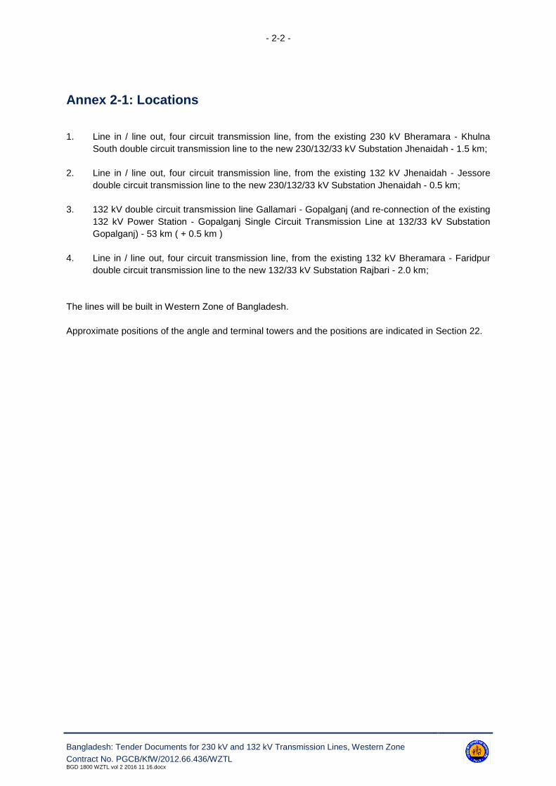
Annex 2-1: Locations
1. Line in / line out, four circuit transmission line, from the existing 230 kV Bheramara - Khulna
South double circuit transmission line to the new 230/132/33 kV Substation Jhenaidah - 1.5 km;
2. Line in / line out, four circuit transmission line, from the existing 132 kV Jhenaidah - Jessore
double circuit transmission line to the new 230/132/33 kV Substation Jhenaidah - 0.5 km;
3. 132 kV double circuit transmission line Gallamari - Gopalganj (and re-connection of the existing
132 kV Power Station - Gopalganj Single Circuit Transmission Line at 132/33 kV Substation
Gopalganj) - 53 km ( + 0.5 km )
4. Line in / line out, four circuit transmission line, from the existing 132 kV Bheramara - Faridpur
double circuit transmission line to the new 132/33 kV Substation Rajbari - 2.0 km;
The lines will be built in Western Zone of Bangladesh.
Approximate positions of the angle and terminal towers and the positions are indicated in Section 22.

- 2-3 -
Bangladesh: Tender Documents for 230 kV and 132 kV Transmission Lines, Western Zone
Contract No. PGCB/KfW/2012.66.436/WZTLBGD 1800 WZTL vol 2 2016 11 16.docx
Annex 2-2: Climatic Conditions
The climatic conditions associated with the site are summarised below. However, the Contractor is ad-
vised to make a thorough study of local climatological records, since no delays to the completion dates
due to adverse weather conditions shall be accepted.
All plant and equipment supplied under the contract shall be entirely suitable for the climatic conditions
prevailing at site.
The project area and vicinity is close to sea level and is in a tropical climate. The ambient shade tem-
perature variation is between 4 °C and 45 °C with periods of high humidity.
Between May and November, low-lying areas are subject to flooding. Flooding countermeasure shall
be taken for the civil design, so as not to affect any equipment or works during the wet season. As per
the recorded past maximum flood water levels in the project area, sufficient ground level height for
land formation is required at the Contractor's responsibility. On certain sites, the flooding can be taken
as an advantage in that the heavy loads may be floated on barges to close proximity of the sites.
The project area is a designated zone of moderate earthquake intensity. The seismic factor is 0.1 g.
Atmospheric pollution is moderate and no special insulator design or washing is required. The area is
subject to high winds of typhoon strength.
Description Unit Required
Maximum ambient shade temperature °C 45
Minimum ambient shade temperature °C 4
Maximum daily average temperature °C 35
Every Day Temperature for design (EDT) °C 30
Maximum annual average temperature °C 25
Maximum wind velocity for line design purposes km/h refer to the tower section
Minimum wind velocity for line rating purposes km/h 3.2
Solar radiation W/m² 1000
Rainfall mm/year 2500
Relative humidity, maximum % 100
Relative humidity, average % 80
Altitude m < 1000
Atmospheric pollution - medium
Icing no ice or snow expected
Seismic factor g 0.1
Soil type - alluvial
Soil temperature (at 1.1 m) °C 30 °C at 1.1 meter depth
Soil thermal resistivity °Cm/W 1.5
Isokeraunic level (thunderstorm days/year) days/year 80
The information in this clause is given solely for the general assistance of Bidders and no responsibil-
ity for it will be accepted nor will any claim based on this clause be considered.

- 3-1 -
Bangladesh: Tender Documents for 230 kV and 132 kV Transmission Lines, Western Zone
Contract No. PGCB/KfW/2012.66.436/WZTLBGD 1800 WZTL vol 2 2016 11 16.docx
3. Quality Assurance
3.1 General
3.1.1 The quality assurance arrangements shall conform to the appropriate sections of BS EN ISO
9001.
3.1.2 The Contractor's / Supplier's quality programme for the works shall define the systems and pro-
cedures adopted to ensure compliance with the contract requirements. These systems shall include
the following:
Hold Point: "A stage in the implementation of project works including material procurement
or fabrication/workmanship process beyond which work shall not proceed with-
out the documented approval of the Engineer or their appointed representa-
tives".
Notification Point: "A stage in the implementation of project works including material procurement
or fabrication/workmanship process for which advance notice of the activity is
required to permit attendance".
3.1.3 The Contractor/Supplier is required to give the Engineer or their appointed representatives the
requisite period of notice of any notification point for which attendance is required.
3.2 Quality Assurance Program
3.2.1 The quality assurance programme shall give a description of the quality system for the works
and shall include the following details:
a. The structure of the Contractor's/Supplier's organization
b. The duties and responsibilities of staff assigned to ensure quality of the work
c. The system for purchasing, taking delivery and verification of materials
d. The system for ensuring quality of workmanship
e. The system for control of documentation
f. The system for retention of records
g. The arrangements for the Contractor's/Suppliers auditing
h. A list of the administrative and work procedures required to achieve and verify the contract's
Quality requirements. These procedures shall be made readily available to the Engineer for in-
spection on request.
3.2.2 The quality assurance programme for the works shall be submitted to the Engineer for approval
within 30 (thirty) days of signing of contract; unless the Contractor's/Supplier's quality system has been
previously audited and approved by the Engineer on behalf of the Employer/Purchaser. This is a Hold
Point.

- 3-2 -
Bangladesh: Tender Documents for 230 kV and 132 kV Transmission Lines, Western Zone
Contract No. PGCB/KfW/2012.66.436/WZTLBGD 1800 WZTL vol 2 2016 11 16.docx
3.3 Quality Plan
A specific quality plan for each section of the work shall be produced by the Contractor and/or Suppli-
er. Each quality plan shall set out the activities in a logical sequence and shall take into account the
following:
a. An outline of the proposed work and programme sequence
b. The structure of the Contractor's and/or Supplier's organisation for the contract
c. The duties and responsibilities of staff assigned to ensure quality of work for the contract
d. Hold and notification points
e. Submission of Engineering documents required by this specification
f. The inspection of materials and components on receipt
g. Reference to the Contractor's and/or Supplier's quality assurance procedures appropriate to
each activity
h. Inspection during fabrication/construction
i. Final inspection and tests.
The Contractor's and/or Supplier's quality plan shall be submitted to the Engineer for approval within
30 (thirty) days of signing of contract. This is a Hold Point.
Notification and hold points are given in Annex 3-1.
3.4 Equivalent Standards
3.4.1 The IEC and BSI standards, together with other references, are listed in the relevant Annex of
each specification. It is the Contractor's / Supplier's responsibility to ensure they are in possession of
the latest edition, including all amendments current on the defined date prior to the bid closing date.
3.4.2 Materials or equipment conforming to alternative international or national standards will be con-
sidered by the Engineer, provided that these standards ensure an equivalent or higher quality.
3.4.3 The Contractor/Supplier shall bring to the attention of the Engineer any inconsistencies between
the requirements of these Standards and this specification.
3.4.4 Where equivalent standard(s) are offered as an alternative, the Contractor/Supplier shall pro-
vide two copies of English language translations of the standard(s) at no extra cost to the contract.
3.5 Quality Control
3.5.1 Inspection and Testing
The prime responsibility for inspection and testing rests with Contractor/Supplier. The inspection and
acceptance of drawings, materials and workmanship; or the waiver of inspection by the Engineer does
not relieve the Contractor/Supplier of any obligations or responsibilities to carry out the work in ac-
cordance with the contract. The inspection and testing shall be documented in such a way that it is
possible to verify that it was undertaken. Records of inspection shall include as a minimum the con-

- 3-3 -
Bangladesh: Tender Documents for 230 kV and 132 kV Transmission Lines, Western Zone
Contract No. PGCB/KfW/2012.66.436/WZTLBGD 1800 WZTL vol 2 2016 11 16.docx
tract identity, the name of inspector/tester, date of inspection/test, operation/inspection, technique
used, acceptance standards, criteria and acceptability.
3.5.2 Type, Sample and Routine Tests
Type, sample and routine tests shall be undertaken as appropriate on all components supplied and/or
installed under this contract, in accordance with the requirements of this specification.
3.5.3 Certificate of Conformity
Prior to the issue of the "Release Certificate" or agreement to shipping, the Contractor/Supplier shall
submit to the Engineer 3 (three) copies of the completed certificate of conformity (see Annex 3-3). The
certificate shall be supported by copies of the appropriate material test certificates, inspection records,
type and sample test reports as detailed in the relevant section of this specification.
The documents to be submitted by the Contractor are listed in Annex 3-4.
3.6 Non-Conforming Products
The Engineer shall review the non-conforming products in accordance with BS EN ISO 9001.
3.7 Monitoring of Quality Assurance Arrangements
Monitoring of quality assurance arrangements may be undertaken by the Engineer/Employer during
the course of the contract. This will take the form of surveillance of the activities at work locations
and/or by formal audits of the Contractor's/Suppliers systems and procedures that constitute his quali-
ty assurance arrangements. Corrective actions shall be agreed and implemented in respect of any de-
ficiencies.
The Contractor/Supplier (including his suppliers or Subcontractors) shall provide all facilities including
access, which may be required by the Engineer/Employer for monitoring activities.
3.8 Suppliers and Subcontractors
The Contractor/Supplier shall ensure that any suppliers or Subcontractors appointed by him under the
contract shall conform to the requirements of this specification. Prior to the appointment of any Suppli-
er/Subcontractor the Contractor/Supplier shall ensure that their quality assurance arrangements com-
ply with the requirements of BS EN ISO 9001 and this specification.
The Contractor's auditing of his Supplier's/Subcontractor's quality assurance arrangements shall be
documented to demonstrate to the Engineer their extent and effectiveness.

- 3-4 -
Bangladesh: Tender Documents for 230 kV and 132 kV Transmission Lines, Western Zone
Contract No. PGCB/KfW/2012.66.436/WZTLBGD 1800 WZTL vol 2 2016 11 16.docx
3.9 Method Statements
Prior to commencing any section of the work, the Contractor shall submit method statements in ac-
cordance with the requirement of the relevant section of this specification. Submission of these meth-
od statements shall be treated as Hold Points.
When requested by the Engineer or their appointed representatives, additional method statements re-
lated to specific items of work shall be provided by the Contractor.

- 3-5 -
Bangladesh: Tender Documents for 230 kV and 132 kV Transmission Lines, Western Zone
Contract No. PGCB/KfW/2012.66.436/WZTLBGD 1800 WZTL vol 2 2016 11 16.docx
Annex 3-1: Notification and Hold Points
Clause Reference Document Description Comment
3.2 Quality Assurance Programme
3.3 Quality Plan
Annex 3-2: Reference Standards
The reference standards and other documents referred to in this chapter of the specification are listed
below:
BS EN ISO 9001 - Model for quality assurance in design, development, production, installation and
servicing.
Annex 3-3: Certificate of Conformity
Certificate of Conformity
To: Director (P&D)
Power Grid Company of Bangladesh Ltd.
IEB Bhaban
Ramna, Dhaka-1000, Bangladesh
From: (Contractor's Details)
Contract: _____________________
We certify that the products detailed below have been inspected, tested and unless noted to the con-
trary, conform in all respects to the requirements.
Quantity Description Attachments Please tick
Test reports (details)
Other (as per relevant sections)
Test reports (details)
Other (as per relevant sections)
Test reports (details)
Other (as per relevant sections)
Date and signature: ___________________
- 3-6 -
Bangladesh: Tender Documents for 230 kV and 132 kV Transmission Lines, Western Zone
Contract No. PGCB/KfW/2012.66.436/WZTLBGD 1800 WZTL vol 2 2016 11 16.docx
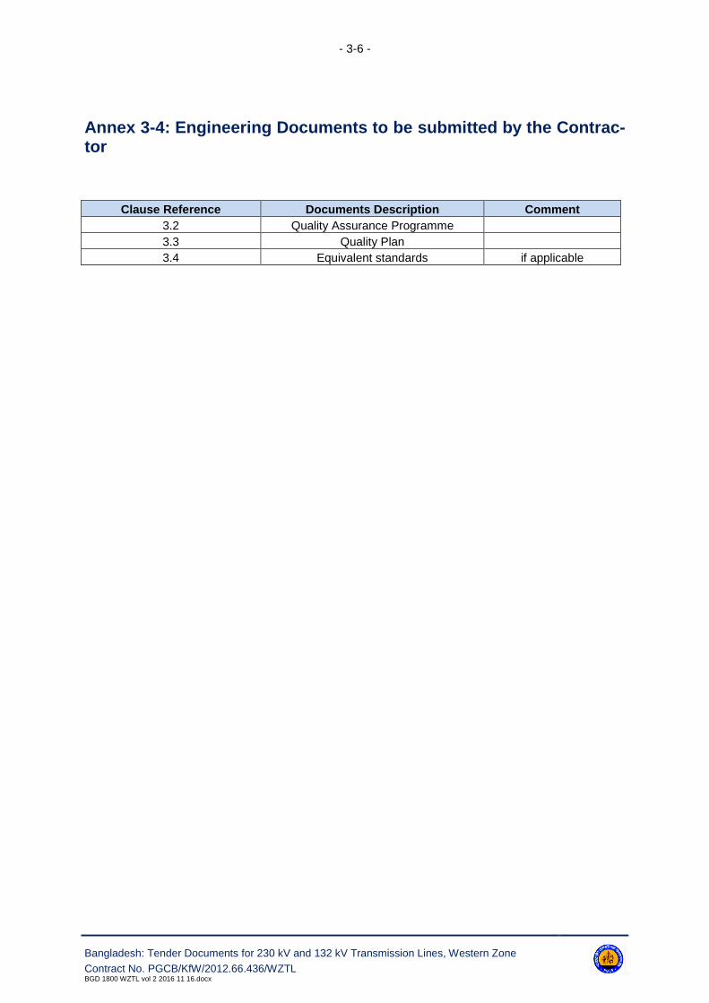
Annex 3-4: Engineering Documents to be submitted by the Contrac-tor
Clause Reference Documents Description Comment
3.2 Quality Assurance Programme
3.3 Quality Plan
3.4 Equivalent standards if applicable
- 3-7 -
Bangladesh: Tender Documents for 230 kV and 132 kV Transmission Lines, Western Zone - Contract No. PGCB/KfW/2012.66.436/WZTL
BGD 1800 WZTL vol 2 2016 11 16.docx
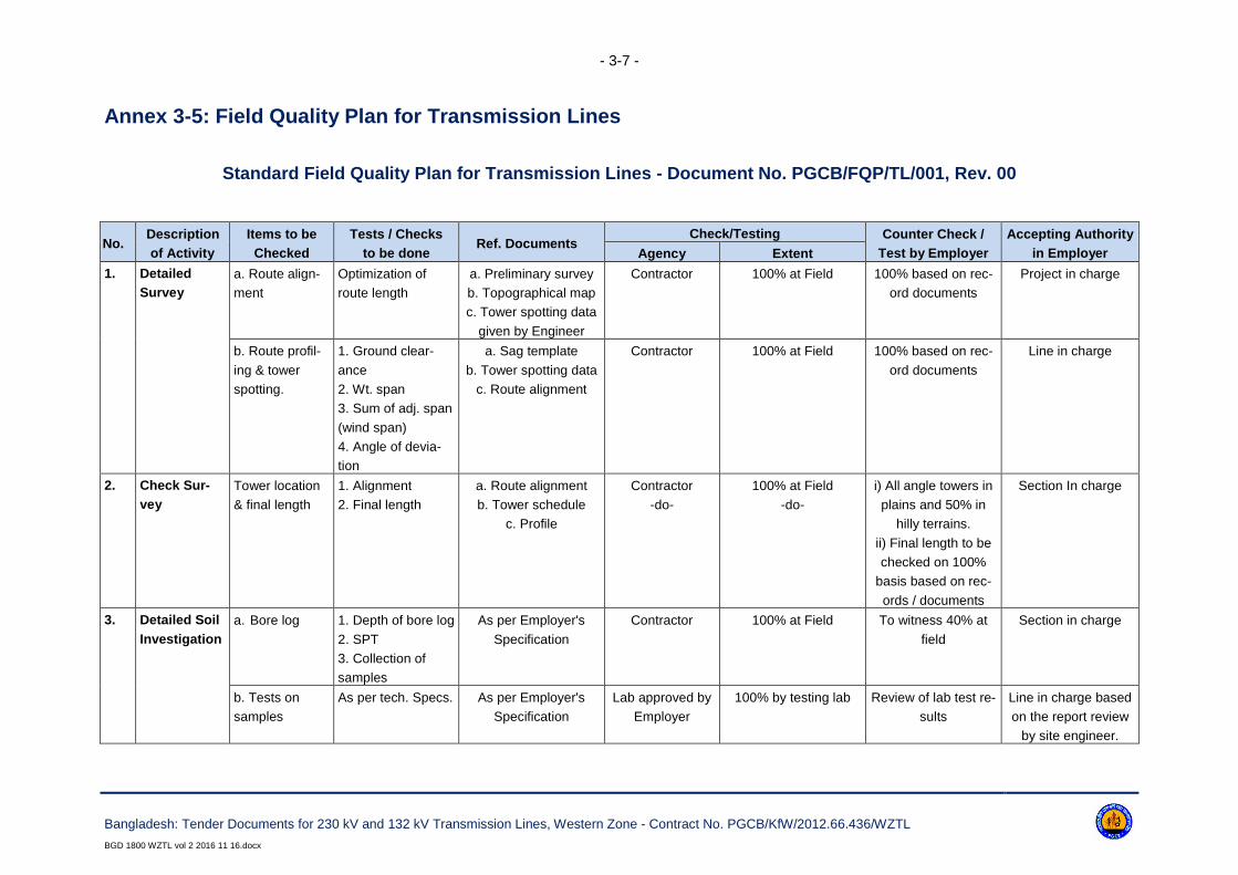
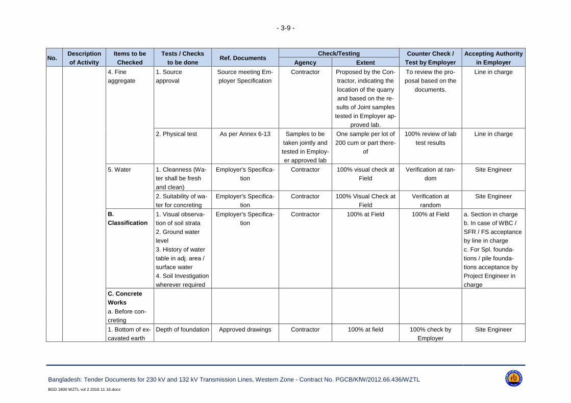
Annex 3-5: Field Quality Plan for Transmission Lines
Standard Field Quality Plan for Transmission Lines - Document No. PGCB/FQP/TL/001, Rev. 00
No.Description
of Activity
Items to be
Checked
Tests / Checks
to be doneRef. Documents
Check/Testing Counter Check /
Test by Employer
Accepting Authority
in EmployerAgency Extent
1. Detailed
Survey
a. Route align-
ment
Optimization of
route length
a. Preliminary survey
b. Topographical map
c. Tower spotting data
given by Engineer
Contractor 100% at Field 100% based on rec-
ord documents
Project in charge
b. Route profil-
ing & tower
spotting.
1. Ground clear-
ance
2. Wt. span
3. Sum of adj. span
(wind span)
4. Angle of devia-
tion
a. Sag template
b. Tower spotting data
c. Route alignment
Contractor 100% at Field 100% based on rec-
ord documents
Line in charge
2. Check Sur-
vey
Tower location
& final length
1. Alignment
2. Final length
a. Route alignment
b. Tower schedule
c. Profile
Contractor
-do-
100% at Field
-do-
i) All angle towers in
plains and 50% in
hilly terrains.
ii) Final length to be
checked on 100%
basis based on rec-
ords / documents
Section In charge
3. Detailed Soil
Investigation
a. Bore log 1. Depth of bore log
2. SPT
3. Collection of
samples
As per Employer's
Specification
Contractor 100% at Field To witness 40% at
field
Section in charge
b. Tests on
samples
As per tech. Specs. As per Employer's
Specification
Lab approved by
Employer
100% by testing lab Review of lab test re-
sults
Line in charge based
on the report review
by site engineer.

- 3-8 -
Bangladesh: Tender Documents for 230 kV and 132 kV Transmission Lines, Western Zone - Contract No. PGCB/KfW/2012.66.436/WZTL
BGD 1800 WZTL vol 2 2016 11 16.docx
No.Description
of Activity
Items to be
Checked
Tests / Checks
to be doneRef. Documents
Check/Testing Counter Check /
Test by Employer
Accepting Authority
in EmployerAgency Extent
4. Tower
Foundation
A. Materials
1. Cement
1. Source approval Source meeting
Employer's Specifica-
tion / approved vendor
Contractor As proposed by Con-
tractor
To verify the pro-
posal based on the
supply made and fac-
tory test results.
Line in charge
2. Physical tests As per Annex 6-10 Samples to be
taken jointly with
Employer and
tested at Employ-
er approved lab
Review of all MTC's
and one sample for
every 500 MT
100% review of lab
test results
Line in charge
3. Chemical Tests
Chemical composi-
tion of Cement
-do- Contractor to
submit MTC
100% review of MTC
by Contractor
100% review of MTC Line in charge
2.
Reinforcement
Steel
1. Source approval To be procured from
main producers only.
Contractor As proposed by Con-
tractor
To review the pro-
posal based on the
documents.
Line in charge.
2. Physical and
chemical analysis
test
As per Annex 6-11 Contractor to
submit MTC
All MTCs 100% review of MTC Line in charge
3. Coarse
Aggregates
1. Source
approval
Source meeting Em-
ployer Specification
Contractor Proposed by the Con-
tractor, indicating the
location of the quarry
and based on the test
results of Joint sam-
ples tested in Employer
approved lab
To review the pro-
posal based on the
documents
Line in charge
2. Physical tests As per Annex 6-12 Samples to be
taken jointly and
tested in Employ-
er-approved lab
One sample per lot of
200 cum or part there-
of
100% review of lab
test results
Line in charge
- 3-9 -
Bangladesh: Tender Documents for 230 kV and 132 kV Transmission Lines, Western Zone - Contract No. PGCB/KfW/2012.66.436/WZTL
BGD 1800 WZTL vol 2 2016 11 16.docx
No.Description
of Activity
Items to be
Checked
Tests / Checks
to be doneRef. Documents
Check/Testing Counter Check /
Test by Employer
Accepting Authority
in EmployerAgency Extent
4. Fine
aggregate
1. Source
approval
Source meeting Em-
ployer Specification
Contractor Proposed by the Con-
tractor, indicating the
location of the quarry
and based on the re-
sults of Joint samples
tested in Employer ap-
proved lab.
To review the pro-
posal based on the
documents.
Line in charge
2. Physical test As per Annex 6-13 Samples to be
taken jointly and
tested in Employ-
er approved lab
One sample per lot of
200 cum or part there-
of
100% review of lab
test results
Line in charge
5. Water 1. Cleanness (Wa-
ter shall be fresh
and clean)
Employer's Specifica-
tion
Contractor 100% visual check at
Field
Verification at ran-
dom
Site Engineer
2. Suitability of wa-
ter for concreting
Employer's Specifica-
tion
Contractor 100% Visual Check at
Field
Verification at
random
Site Engineer
B.
Classification
1. Visual observa-
tion of soil strata
2. Ground water
level
3. History of water
table in adj. area /
surface water
4. Soil Investigation
wherever required
Employer's Specifica-
tion
Contractor 100% at Field 100% at Field a. Section in charge
b. In case of WBC /
SFR / FS acceptance
by line in charge
c. For Spl. founda-
tions / pile founda-
tions acceptance by
Project Engineer in
charge
C. Concrete
Works
a. Before con-
creting
1. Bottom of ex-
cavated earth
Depth of foundation Approved drawings Contractor 100% at field 100% check by
Employer
Site Engineer

- 3-10 -
Bangladesh: Tender Documents for 230 kV and 132 kV Transmission Lines, Western Zone - Contract No. PGCB/KfW/2012.66.436/WZTL
BGD 1800 WZTL vol 2 2016 11 16.docx
No.Description
of Activity
Items to be
Checked
Tests / Checks
to be doneRef. Documents
Check/Testing Counter Check /
Test by Employer
Accepting Authority
in EmployerAgency Extent
2. Stub setting 1) Centre Line
2) Diagonals
3) Level of stubs
-do- -do- -do- -do- -do-
3. Reinforce-
ment steel
Placement Bar bending schedule -do- -do- -do- -do-
b. During con-
creting
1. Workability Slump test Range 50 mm to
100 mm refer docu-
ment at Annex 6-14
Contractor 100% at field 40% check at ran-
dom
Site Engineer
2. Concrete
strength
Cubes comp
strength
PWD SPEC as re-
ferred in document at
Annex 6-14
Casting of cubes
at site. Cubes to
be tested at Em-
ployer-approved
lab for 28 days
strength
One sample of 4 cubes
in each tower locations
/ per
6 cum concreting / per
day work
100% review of lab
test results. Cubes at
40% location are to
be taken in presence
of Employer's offi-
cials
Section in charge
5. Pile founda-
tions
1. All materials
like cement,
steel, coarse /
fine aggregate,
water
To be tested as per procedure enumerated in the respective columns above
2. Before con-
creting
1. Check for centre
line of each pile
Approved Drawings Contractor 100% 100% Site Engr.
2. Check for diame-
ter / verticality of
each pile
-do- -do- -do- -do- -do-
3. Check for depth
of each pile
-do- -do- -do- -do- -do-
3. During con-
creting
a. Workability 1. Slump test 150-200 mm as per
Employer's Specif.
Contractor For each pile 100% at field Site ENGINEER

- 3-11 -
Bangladesh: Tender Documents for 230 kV and 132 kV Transmission Lines, Western Zone - Contract No. PGCB/KfW/2012.66.436/WZTL
BGD 1800 WZTL vol 2 2016 11 16.docx
No.Description
of Activity
Items to be
Checked
Tests / Checks
to be doneRef. Documents
Check/Testing Counter Check /
Test by Employer
Accepting Authority
in EmployerAgency Extent
b. Concrete
strength
2. Cubes compres-
sive strength
As per Employer's
specifications
Contractor.
One set of cubes
(min. 4 pieces) to
be taken and
tested for 7 & 28
days strength at
Employer-app-
roved laboratory
One set for each pile.
For pile caps, beams,
chimney, one sample
for every 6 m³ or part
thereof for each day of
concreting.
100% cubes for piles,
20% pile caps,
beams, chimney etc.
to be taken in pres-
ence of Employer's
officials.
100% review of test
results.
Section in charge.
6. Tower
Erection
1. Materials
a. Tower mem-
ber / bolts &
nuts / washers /
accessories
Visual checking for
1. Stacking
2. Cleanliness
3. Galvanizing
4. Damages
Approved drawings /
BOM
Contractor 100% at stores 100% verification of
records
Site Engineer
2. Erection of
super-structure
1. Sequence of
erection
As per approved draw-
ings / Employer's spec-
ifications
Contractor 100% at field 100% check Site Engineer
2. Check for com-
pleteness
-do- -do- -do- -do- -do-
3. Tightening of
nuts and bolts
-do- -do- -do- -do- -do-
4. Check for verti-
cality
-do- -do- -do- -do- -do-
5. Tack welding for
bolts & nuts
Employer's Specifica-
tions
Contractor 100% at field 100% check Site Engineer
3. Tower footing
resistance
(TFR)
TFR at locations
before and after
earthing.
Employer's Specifica-
tions
Contractor 100% at field 20% locations to be
verified
Line in charge
7. Stringing 1. Materials
a. Insulators 1. Visual check for
cleanliness/glazing/
cracks/white spots.
Employer's Specifica-
tions
Contractor 100% at Field 100% verification of
records and to carry
random checks 10%
Site Engineer

- 3-12 -
Bangladesh: Tender Documents for 230 kV and 132 kV Transmission Lines, Western Zone - Contract No. PGCB/KfW/2012.66.436/WZTL
BGD 1800 WZTL vol 2 2016 11 16.docx
No.Description
of Activity
Items to be
Checked
Tests / Checks
to be doneRef. Documents
Check/Testing Counter Check /
Test by Employer
Accepting Authority
in EmployerAgency Extent
2. IR Value (min. 50 MOhms) -do- One test per sample
size of 20 for every lot
of 10,000
To verify Contractor's
records 100% and
joint check 20% of
total tests
-do-
3. E&M test - Insulator supplier a. 20 per 10,000 for
discs b. 3 per 1500 for
long rod
Collection of sam-
ples, sealing them
and handing over by
Employer to insulator
supplier
Tests to be witnessed
/ Approved by QA & I
at Manufacturer's
works
4. Traceability
(make / batch no. /
locations where in-
stalled)
Packing list/CIP Contractor 100% at field 100% Review of rec-
ords
Site Engineer
b. Conductor On receipt,
1. Visual check of
drum.
Packing list Contractor 100% at stores 20% check Site Engineer
2. Check for seals
at both ends, and
Employer's sticker
on outer end
-do- -do- -do- -do- -do-
3. Check depth
from top of flange
to the top of the
outer most layer
-do- -do- -do- -do- -do-
c. Earthwire Check for seals at
both ends
Packing list Contractor 100% at stores 20% check -do-
2. Field
activity
a. Before string-
ing
Readiness for
stringing
Stringing procedures
as per approved speci-
fications
Contractor Readiness
certificate to be submit-
ted by the Contractor
Review of
Certificate
Line in charge

- 3-13 -
Bangladesh: Tender Documents for 230 kV and 132 kV Transmission Lines, Western Zone - Contract No. PGCB/KfW/2012.66.436/WZTL
BGD 1800 WZTL vol 2 2016 11 16.docx
No.Description
of Activity
Items to be
Checked
Tests / Checks
to be doneRef. Documents
Check/Testing Counter Check /
Test by Employer
Accepting Authority
in EmployerAgency Extent
b. During string-
ing
(Conductor / earth-
wire)
1. Scratch/cut
check (visual)
Approved drawings/
Employer's specifica-
tions
Contractor 100% at Field 100% record & field
check
20%
Site Engineer
2. Repair sleeve -do- -do- -do- -do- -do-
3. Mid span Joints -do- -do- -do- -do- -do-
4. Guying (in case
of towers not de-
signed for one side
stringing)
Approved guying ar-
rangement / Employ-
er's specifications
-do- -do- 100% Section in charge
c. After stringing Check for
1. Sag/Tension Sag tension chart /
tower spotting data
-do- -do- 100% record & field
check
20%
Site Engineer
2. Electrical clear-
ances
As per approved draw-
ings / Employer's spec-
ifications
-do- -do- -do- -do-
i) Ground clearance -do- -do- -do- -do- -do-
ii) Live metal clear-
ance etc.
-do- -do- -do- -do- -do-
3. Jumpering -do- -do- -do- -do- -do-
4. Placement of
spacer/damper
As per specification /
drawings / placement
chart
-do- -do- -do- -do-
8. Final Testing
a. Pre- com-
missioning of
lines
a. Readiness of
lines for pre-
commissioning
1. Completeness of
line.
2. Meggar test of
line
As per approved draw-
ings / Employer's latest
pre-commissioning
procedures
Contractor 100% 100% joint
checking
Project in charge
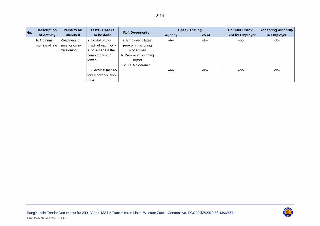
- 3-14 -
Bangladesh: Tender Documents for 230 kV and 132 kV Transmission Lines, Western Zone - Contract No. PGCB/KfW/2012.66.436/WZTL
BGD 1800 WZTL vol 2 2016 11 16.docx
No.Description
of Activity
Items to be
Checked
Tests / Checks
to be doneRef. Documents
Check/Testing Counter Check /
Test by Employer
Accepting Authority
in EmployerAgency Extent
b. Commis-
sioning of line
Readiness of
lines for com-
missioning
2. Digital photo-
graph of each tow-
er to ascertain the
completeness of
tower.
a. Employer's latest
pre-commissioning
procedures
b. Pre-commissioning
report
c. CEA clearance
-do- -do- -do- -do-
3. Electrical Inspec-
tors clearance from
CEA
-do- -do- -do- -do-

- 3-15 -
Bangladesh: Tender Documents for 230 kV and 132 kV Transmission Lines, Western Zone - Contract No. PGCB/KfW/2012.66.436/WZTL
BGD 1800 WZTL vol 2 2016 11 16.docx
Annex 3-6: Acceptance Criteria and Permissible Limits for Cement
1. Mechanical and physical requirements given as characteristic values
Strength
Class*
Early Strength Standard Strength Initial Setting Time
(min.)
Soundness
(mm)2 days 7 days 28 days
32.5N - ≥ 16.0 ≥ 32.5 ≥ 75.0
≤ 10.0
32.5R ≥ 10.0 -
42.5N ≥ 10.0 -≥ 42.5 ≥ 60.0
42.5R ≥ 20.0 -
52.5N ≥ 20.0 -≥ 52.5 ≥ 45.0
52.5R ≥ 30.0 -
2. Chemical requirements given as characteristic values
Property Strength Class* Requirements
Loss on ignition All ≤ 5.0%
Insoluble residue All ≤ 5.0%
Sulphate content
32.5N
32.5R
42.5N
≤ 3.5%
42.5R
52.5N
52.5R
≤ 4.0%
Chloride content All ≤ 0.1%
* A class with ordinary early strength, indicated by N and a class with high early strength indicat-
ed by R.
* The requirements are not limited to, those mentioned above. For details of the requirements
shall be made to the BS EN 197-1.

- 3-16 -
Bangladesh: Tender Documents for 230 kV and 132 kV Transmission Lines, Western Zone - Contract No. PGCB/KfW/2012.66.436/WZTL
BGD 1800 WZTL vol 2 2016 11 16.docx
Annex 3-7: Acceptance Criteria and Permissible Limits for Rein-forcement Steel
No. Name of the Test
Carbon Steel Bars as per BS 4449
RemarksGrade 250 Grade 460
i) Chemical analysis test
Carbon 0.25% max. 0.25% max.
Sulphur 0.06% max. 0.05% max.
Phosphorus 0.06% max. 0.05% max.
ii) Physical tests
Specified characteristic strength 250 N/mm³ 460 N/mm³ Testing in approved lab
Minimum elongation 22% 12% Testing in approved lab
iii) Bend & re-bend tests Pass Pass Testing in approved lab
The requirements are not limited to those mentioned above. For details of the requirements, refer to
BS 4449.

- 3-17 -
Bangladesh: Tender Documents for 230 kV and 132 kV Transmission Lines, Western Zone - Contract No. PGCB/KfW/2012.66.436/WZTL
BGD 1800 WZTL vol 2 2016 11 16.docx
Annex 3-8: Acceptance Criteria and Permissible Limits for Coarse Aggregate
3.
Coarse Aggregates - Physical Tests
a. Determination of
particles size
a. Sieve
Designation
Percentage passing for Single-Sized Aggregate
of Nominal Size
Percentage Passing for Grades Aggregate of
Nominal Size
40 mm 20 mm 16 mm 12.5 mm 10 mm 40 mm 20 mm 16 mm 12.5 mm
63 mm 100 - - - - - - - -
40 mm 85 - 100 100 - - - 95 - 100 100 - -
20 mm 0 - 20 85 - 100 100 - - 30 - 70 95 - 100 100 100
16 mm - - 85 - 100 100 - - - 90 - 100 -
12.5 mm - - - 85 - 100 100 - - - 90 - 100
10 mm 0 - 5 0 - 20 0 - 30 0 - 45 85 - 100 10 - 35 25 - 35 30 - 70 40 - 85
4.75 mm - 0 - 5 0 - 5 0 - 10 0 - 20 0 - 5 0 - 10 0 - 10 0 - 10
2.36 mm - - - - 0 - 5 - - - -
b. Flakiness index Not to exceed 25%
c. Crushing value Not to exceed 45%
d. Presence of deleterious material Total presence of deleterious materials not to exceed 5%
e. Soundness test (for concrete
work subject to frost action)
12% when tested with sodium sulphate and 18% when tested with magnesium sulphate

- 3-18 -
Bangladesh: Tender Documents for 230 kV and 132 kV Transmission Lines, Western Zone - Contract No. PGCB/KfW/2012.66.436/WZTL
BGD 1800 WZTL vol 2 2016 11 16.docx
Annex 3-9: Acceptance Criteria and Permissible Limits for Fine Aggregate
4 Fine aggregates - Physical Tests Sieve Designation
Percentage Passing for Graded Aggregate of Nominal Size
F.A. Type I F.A. Type II F.A. Type III
a) Determination of particle size 10 mm 100 100 100
4.75 mm 90 - 100 90 - 100 90 - 100
2.36 mm 60 - 95 75 - 100 85 - 100
1.18 mm 30 - 70 55 - 90 75 - 100
600 microns 12.5 mm 15 - 34 35 - 59 60 - 79
300 microns 5 - 20 8 - 30 12 - 40
150 microns 0 - 10 0 - 10 0 - 10
b) Silt content Not to exceed 8% Not to exceed 8% Not to exceed 8%
c) Presence of deleterious material Total presence of deleterious materials shall not exceed 5%
d) Soundness Applicable to concrete work
subject to frost action
12% when tested with sodium sulphate and 15% when tested with magnesium sulphate

- 3-19 -
Bangladesh: Tender Documents for 230 kV and 132 kV Transmission Lines, Western Zone - Contract No. PGCB/KfW/2012.66.436/WZTL
BGD 1800 WZTL vol 2 2016 11 16.docx
Annex 3-10: Acceptance Criteria and Permissible Limits for Concrete Work
1) Concrete a) Workability Slump shall be recorded by slump cone method and it shall between 50-100 mm for pile cap and
chimney, 150mm to 200mm for concrete pile.
b) Compressive strength One set for each pile. For Pile caps, beams, Chimney, one set for every 6 Cu.m. or part thereof for
each day of concreting. Each set consists of four cubes, one for 7 days testing and two for 28 days
testing shall be taken.
Notes - Acceptance Criteria are based on 28 days compressive strengths for nominal mix concrete:
a. The average of the strength of three specimen be accepted as the compressive strength of the concrete, provided the strength of any individual
cube shall neither be less than 70% nor higher than 130% of the specified strength.
b. If the actual average strength of accepted sample exceeds specified strength by more than 30%, the Engineer-in-charge, if he so desires, may fur-
ther investigate the matter. However, if the strength of any individual cube exceeds more than 30% of the specified strength, it will be restricted to 30%
only for computation of strength.
c. If the actual average strength of accepted sample is equal to or higher than specified up to 30%, the strength of the concrete shall be considered in
order and the concrete shall be accepted at full rates.
d. If the actual average strength of accepted sample is less than specified strength but not less than 70% of the specified strength, the concrete may be
accepted at reduced rate at the discretion of Engineer-in-charge.
e. If the actual average strength of accepted sample is less than 70% of specified strength, the Engineer-in-charge shall reject the defective portion
of work represent by sample and nothing shall be paid for the rejected work. Remedial measures necessary to retain the structure shall take at
the risk and cost of Contractor. If, however, the Engineer-in-charge so desires, he may order additional tests to be carried out to ascertain if the
structure can be retained. All the charges in connection with these additional tests shall be borne by the Contractor.
General Notes:
1. This standard Field Quality Plan is not to limit the supervisory checks that are otherwise required to be carried out during execution of work as
per drawings/Technical specifications etc.
2. Contractor shall be responsible for implementing/documenting the quality plan. Documents shall be handed over by the Contractor to Employer after
the completion of the work.
3. Project in charge means over all in charge of work. Line In charge means in charge of the line. Section in-charge means in charge of the section.
4. Acceptance criteria and permissible limits for tests are indicated in the Annexure. However for further details/tests Employer
5. specification and relevant standards shall be referred.
6. Tests as mentioned in this FQP shall generally be followed. However Employer reserves the right to order additional tests wherever required neces-
sary at the cost of the Contractor.
- 3-1 -
Bangladesh: Tender Documents for 230 kV and 132 kV Transmission Lines, Western Zone
Contract No. PGCB/KfW/2012.66.436/WZTLBGD 1800 WZTL vol 2 2016 11 16.docx
Annex 3-11: Approximate Positions of Towers
Approximate positions of the angle and terminal towers and the positions of such intermediate towers
as it may have been desirable to determine during preliminary wayleave negotiations are indicated on
Reference data given in Section 23.
The conceptual drawings for line elements are indicated on the List of Drawings in Section 22.

- 4-1 -
Bangladesh: Tender Documents for 230 kV and 132 kV Transmission Lines, Western Zone
Contract No. PGCB/KfW/2012.66.436/WZTLBGD 1800 WZTL vol 2 2016 11 16.docx
4. Design Particulars
4.1 Philosophy of Design
4.1.1. The philosophy of design in this specification is based upon deterministic principles, whereby
the applied loading multiplied by the appropriate safety factor must be less than the ultimate strength
of the component.
4.1.2. In bidding the Contractor/Supplier will be deemed to have concurred, as an experienced Manu-
facturer, with the design and layout of the works as being sufficient to ensure reliability and safety in
operation, freedom from undue stresses and satisfactory performance in all other essentials as a
working plant.
4.1.3. The transmission line(s) shall be designed with high reliability and low cost maintenance as the
primary consideration in accordance with the relevant sections of the Specification.
4.1.4. The design shall incorporate all reasonable precautions and provisions for the safety of those
concerned in the erection and subsequent maintenance of the contract works.
4.1.5. The contract comprises design of new towers for completely new 230 kV double circuit lines on-
ly. For all other transmission line the existing PGCB’s design shall be used.
4.1.6. None of the 132 kV and 230 kV towers for line in / line out are to be designed by the Con-
tractor. The Employer shall provide structural/erection drawings, available shop drawings, bill of mate-
rials of all types of transmission line towers and their extensions, and special towers as required to the
Contractor after placement of award, in sequence, suiting the project requirement.
4.1.7. The copies of prototype load-tested towers structural drawings and available shop drawings
will be provided to the Contractor by the Employer upon request by the Contractor. However, if the
Contractor needs to prepare any additional structural and shop drawings or make any correction of ex-
isting drawings, that have to be prepared by the Contractor without any additional cost.
4.1.8. Bidders are requested to inspect the available drawings in the Design Dept. of PGCB to sat-
isfy them regarding the extent of available drawings. Bidders are required to propose the tower mate-
rials from a manufacturer who will use the same material standard as mentioned in the tower draw-
ings.
4.2 Units of Measurement
In all correspondence, technical schedules, design calculations and drawings, the metric (SI) units of
measurement shall be used. Angular measurement shall be degrees, with 90° comprising a right an-
gle.

- 4-2 -
Bangladesh: Tender Documents for 230 kV and 132 kV Transmission Lines, Western Zone
Contract No. PGCB/KfW/2012.66.436/WZTLBGD 1800 WZTL vol 2 2016 11 16.docx
4.3 Document Submission
The Contractor/Supplier shall submit to the Engineer all design calculation drawings, method state-
ments, test programmes, test records etc. as defined in the different chapters of the specifications, or
as otherwise agreed by the Engineer. For details of the number of copies and time periods for approv-
al, reference should be made to Annex 4-1.
4.4 Design Calculations
4.4.1 All sets of calculations shall be complete, bound, properly titled and given a unique drawing
number (see clause 4.5.1). The binding shall be such as to allow the easy introduction of subsequent
pages if necessary.
4.4.2 Bound into each set shall be a fully detailed index. Following this shall be a design information
sheet(s) which shall incorporate the following details:
a. The design concept shall be summarised;
b. Full details of manuals, design papers or other aids referred to in the text shall be given, with
photocopies of relevant sheets if appropriate;
c. Full loading shall be reiterated, with their derivation if appropriate;
d. Design stresses shall be reiterated;
e. Code or standard references should be quoted, and equations written out in full for initial calcu-
lations;
4.4.3 Should the Contractor/Supplier be required to re-submit amended calculation or additional
sheet(s), the following annotation shall be adopted:
7. Amended sheets should retain the same sheet number, but have a lower case revision letter
suffix i.e. sheet 14 when amended becomes 14a, then 14b.
8. Additional sheets that needed to be inserted shall be given the sheet number they are added to,
plus an upper case letter prefix i.e. additional sheets to piece 60 become A60, B60 etc. and if
subsequently amended A60a etc.
4.4.4 Where computer programs are used for design calculations, a full explanation in English lan-
guage shall be provided to assist the Engineer's approval of the calculations for each and every pro-
gram used. Details must include name of program, author, source, comprehensive description of theo-
retical basis including all references to relevant documentation, checks undertaken on program and a
list of projects on which the program has been used.
4.5 Drawings
4.5.1 General Requirements
4.5.1.1. Drawings shall be to scale, fully detailed and all dimensions shall be in metric units. Gen-
eral arrangement drawings submitted shall be to a scale of not less than 1 to 50 and all detailed draw-

- 4-3 -
Bangladesh: Tender Documents for 230 kV and 132 kV Transmission Lines, Western Zone
Contract No. PGCB/KfW/2012.66.436/WZTLBGD 1800 WZTL vol 2 2016 11 16.docx
ings not less than 1 to 20. Profile drawings shall normally be drawn to vertical scale of 1 to 200 and a
horizontal scale of 1 to 2,000.
4.5.1.2. Drawings sheets shall conform in size to BS ISO 5457, mainly A0, A1, A2, A3 and A4.
The sheet size is to be stated on the drawing within or adjacent to the title block. Drawings shall be to
BS 308 or equivalent.
4.5.1.3. The scale used shall be stated on the drawing as a ratio together with a linear scale at a
convenient position along the margin of the original drawing sheet.
4.5.1.4. The physical drafting requirements in respect of line density, strength, contrast, spacing
and character liability shall be met to ensure drawings are suitable for copying.
4.5.1.5. All drawings shall bear English title, serial number of the main contract, drawing number
unique to this contract and scale. The system of numbering and layout of the title block will be to the
approval of the Employer. The title block shall include the name and address of the Employer. The re-
vision notes shall detail the nature of each revision. The revision shall be enclosed in a cloud with the
revision letter indicated.
4.5.2 Computer Generated Drawings/Designs
All drawings shall be prepared using AutoCAD software version 2007 or later only. Drawings, which
are not compatible to AutoCAD software version 2007 or later shall not be accepted. After final ap-
proval all the drawings (structural drawings, BOMs, shop sketches and tower accessories, hardware
fittings, plan & profile, sag curve, etc. drawings) shall be submitted to the Employer on CDs.
In addition to the hardcopy of drawings/designs the contract is required to submit soft copy of all the
drawings in AutoCAD format and all related documents in Microsoft Word/Excel format. For drawings /
designs developed by PLS-CADD or STAAD PRO or any other software, the soft copy of the input
files and other related files are also required to be submitted during submission of hardcopy for ap-
proval.
4.5.3 Contract Drawing List
At defined intervals the Contractor/Supplier shall submit the required number of copies of the contract
drawing list.
The list shall contain the following information:
a. Drawing number;
b. Drawing title;
c. Revision status;
d. Submission date.
e. Date of receipt of comments/approval.
f. Approval status.
All changes since the previous issue shall be clearly indicated and when agreed only the front (index)
sheet and revised sheets need to be submitted.

- 4-4 -
Bangladesh: Tender Documents for 230 kV and 132 kV Transmission Lines, Western Zone
Contract No. PGCB/KfW/2012.66.436/WZTLBGD 1800 WZTL vol 2 2016 11 16.docx
4.5.4 Contract Record Drawings
The Contractor/Supplier shall submit to the Engineer:
a. A final issue of the contract drawing list indicating which of the drawings, design calculations,
method statements etc. he proposes to issue as final contract drawings. These drawings shall
be updated to incorporate all modifications made during erection and commissioning
b. Requisite number of prints of each schedule, including where appropriate the supply and instal-
lation material manual
c. Requisite number of drawings, including design calculations, schedules including the supply
and Installation Material Manual on CD-ROM in WPG / DXF / PDF / DWG / DOC format. The
tower drawings and plan & profile drawings shall be submitted in AutoCAD format.
The distribution of the contract record drawings will be advised by the Engineer.
4.5.5 Route Maps
4.5.5.1 During the progress of the work the Contractor shall record on profiles, tower and Installa-
tion Material Manual (SIMMs) and on a set of survey maps of approved scale such particulars as will
allow an accurate reference to be made afterwards in case of any faults or projected modifications to
the line.
4.5.5.2 The map and/or profile sheet shall show the exact position of every tower with approved
reference marks. The maps shall be supplemented, or profiles marked by sketches where necessary,
to delineate boundary positions of towers which cannot be clearly indicated on the maps.
4.5.5.3 The data included on the maps, profile, sketches and SIMMs shall be submitted to the
Engineer, to whom facilities shall be given for examining such records during the progress of the work.
4.6 Sag Templates (not used)
4.7 Supply and Installation Material Manual (SIMM)
As soon as final support positions are selected and approved, the Contractor shall provide the requi-
site copies of the A4 size Supply and Installation Material Manual (SIMM).
Each tower position shall be represented by one sheet of the, manual with the following information
recorded:
a. Provisional and final tower numbers;
b. Profile and Record Map reference drawing numbers;
c. Span;
d. Wind span;
e. Weight span;
f. Angle of deviation;

- 4-5 -
Bangladesh: Tender Documents for 230 kV and 132 kV Transmission Lines, Western Zone
Contract No. PGCB/KfW/2012.66.436/WZTLBGD 1800 WZTL vol 2 2016 11 16.docx
g. Tower type, leg and body extensions and general arrangement (G.A.) drawing reference num-
bers;
h. Foundation type and G.A. drawing reference number;
i. Earthing details and G.A. drawing reference number;
j. Insulator set details and G.A. drawing reference number;
k. Sag adjustment setting, and linkage requirements where appropriate;
l. Phase conductor jumper details including spacer and general arrangement drawing reference
number where appropriate;
m. Earthwire set details and G.A. drawing reference number;
n. Earthwire vibration damper G.A. drawing reference number;
o. Aircraft navigation (obstruction aids) drawing reference number where appropriate;
p. Fibre optic junction boxes and cabling G.A. drawing reference number where appropriate;
In addition the following schedules shall be included:
9. Phase conductor and earthwire sags and tensions (erection and final);
10. Suspension insulator set off-sets;
11. Location and spacing of phase conductor spacers and spacer dampers (where appropriate);
12. Location of all phase conductor and earthwire tension and non-tension joints;
13. Location and spacing of all aircraft warning spheres (where appropriate);
14. Location of all fibre optic joint boxes - (where appropriate).
The appropriate reference drawing numbers shall also be included. Preliminary copies of SIMMs shall
be available prior to any site work commencing, together with material summaries. This is a Hold
Point.
4.8 Maintenance Manual
4.8.1 The Contractor/Supplier shall provide to the Engineer at the specified period before the end of
the construction period of the contract, a maintenance manual covering the following information:
a. Type, code number and description of all plant erected, together with names and addresses of
manufacturer;
b. Methods of assembly of all fittings;
c. Method of replacing any part of the plant including the use of maintenance holes provided on
the support, access provisions and where appropriate the application of 'live-line' maintenance
techniques;
d. Recommendations of preventive maintenance including frequency of inspections;
e. List of recommend maintenance equipment with a description of its use and limitations;
f. Type and application of temporary earthing equipment;
g. Personnel safety equipment requirements and any risk assessments required.
4.8.2 The above information must be as specified in this contract and entirely in the English language.
4.8.3 Drawings and diagrams shall be used where necessary to enable the proper maintenance of
the whole works.
4.8.4 The manual shall be suitably bound within a hard cover, and all materials used shall be reason-
ably hard wearing.

- 4-6 -
Bangladesh: Tender Documents for 230 kV and 132 kV Transmission Lines, Western Zone
Contract No. PGCB/KfW/2012.66.436/WZTLBGD 1800 WZTL vol 2 2016 11 16.docx
4.8.5 The manual shall be submitted to the Engineer. This is a Hold Point.
4.9 Samples and Models
If the nature of the works makes it desirable, the Contractor/Supplier may be asked to submit or pre-
pare for the Engineer such samples, patterns and models as the Engineer may reasonably require for
the purpose of design approval at the expense of the Contractor/Supplier.
4.10 Photographs
The Contractor/Supplier shall make all arrangements to provide progress photographs of all tests and
such sections of the work in progress as directed by the Employer. Each photograph shall be of size
25 cm x 20 cm suitably titled. The negatives and/or electronic files of the photographs shall be the
property of the Employer and no prints from these negatives and/or electronic files shall be supplied to
any persons unless under the authority of the Employer.
The Contractor/Supplier will normally be required to provide every month at his own cost the 3 (three)
sets of unmounted progress photographs suitably inscribed, on portions of the work - in progress,
throughout the period of construction. Any variation to these quantities will only be with the permission
of the Employer.

- 4-7 -
Bangladesh: Tender Documents for 230 kV and 132 kV Transmission Lines, Western Zone
Contract No. PGCB/KfW/2012.66.436/WZTLBGD 1800 WZTL vol 2 2016 11 16.docx
Annex 4-1: Time Intervals for Document Submission, Test and In-spection Notification, and Number of Submission Copies
ItemTime Interval
(Weeks)
Notification
Period (Days)
No. of
Copies
Submission of:
Contract drawing list 4 - 5
Maintenance Manual 26 - 10
Method statement:
15. Overall 12 - 5
16. Detailed 4 - 5
Work Programme - 5
Reports:
17. Weekly reports 1 - 5
18. Monthly reports 4 - 5
Quality Assurance Programme 4 - 5
Quality Plan 4 - 5
Preliminary supply and installation material manual 12 - 5
Time intervals:
Currency of standards 4 - -
Drawing approval 3 - -
Profile approval and commencement of site work x - -
Commencement of work after issue of notice 1 - -
Suspension of work 1 - -
Notification periods:
Prototype test of towers - type test
19. overseas 28
20. local 7
Sample test - overseas 14
Inspection of work on site 3
Final line inspection 14
Commencement of survey 7
Stringing of conductor across roads, etc. 7
Number of copies:
Drawings for approval 5
Approved drawings 5
Test program incl. prototype test of towers 5
Final supply installation material manuals 5
Installation instructions 6
Contract records:
21. Prints 1
22. CDs 5
Test reports 5
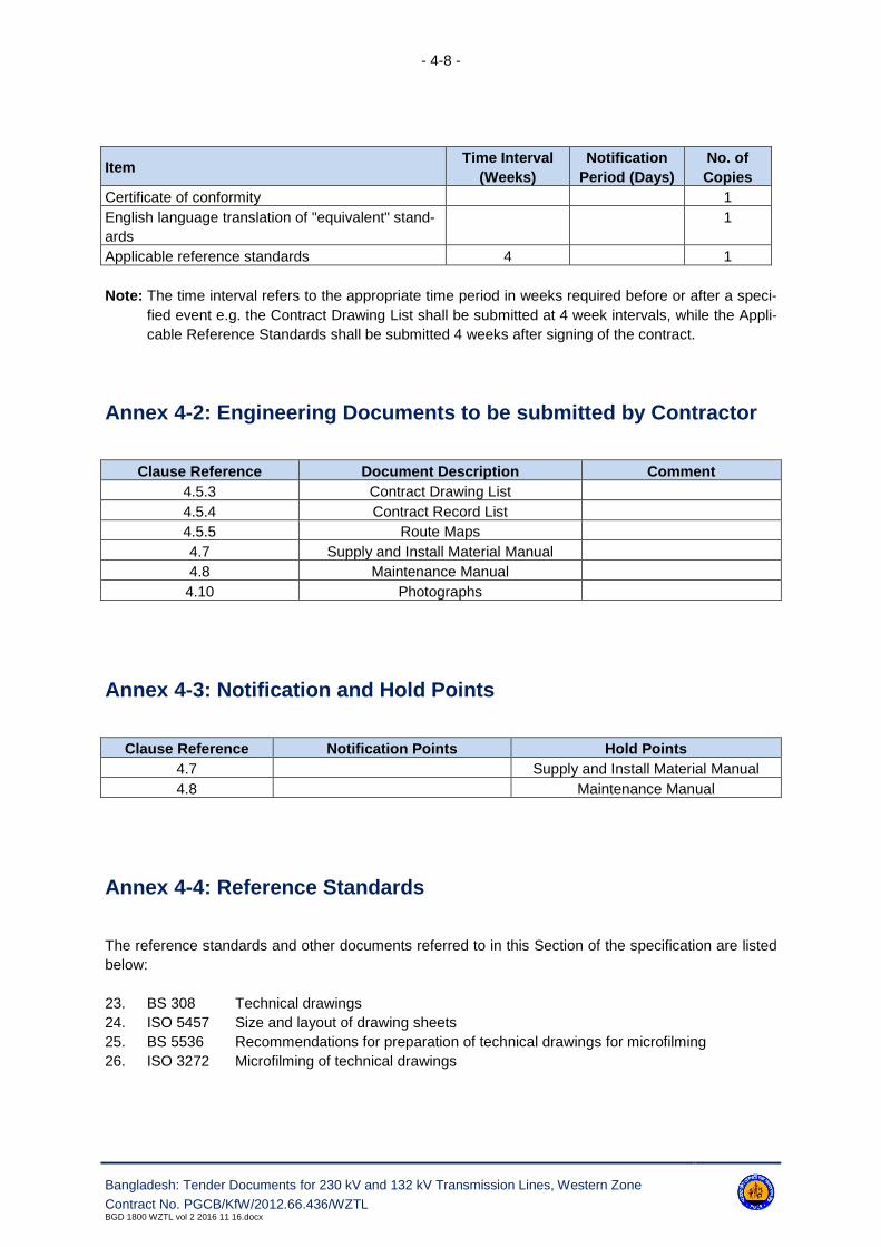
- 4-8 -
Bangladesh: Tender Documents for 230 kV and 132 kV Transmission Lines, Western Zone
Contract No. PGCB/KfW/2012.66.436/WZTLBGD 1800 WZTL vol 2 2016 11 16.docx
ItemTime Interval
(Weeks)
Notification
Period (Days)
No. of
Copies
Certificate of conformity 1
English language translation of "equivalent" stand-
ards
1
Applicable reference standards 4 1
Note: The time interval refers to the appropriate time period in weeks required before or after a speci-
fied event e.g. the Contract Drawing List shall be submitted at 4 week intervals, while the Appli-
cable Reference Standards shall be submitted 4 weeks after signing of the contract.
Annex 4-2: Engineering Documents to be submitted by Contractor
Clause Reference Document Description Comment
4.5.3 Contract Drawing List
4.5.4 Contract Record List
4.5.5 Route Maps
4.7 Supply and Install Material Manual
4.8 Maintenance Manual
4.10 Photographs
Annex 4-3: Notification and Hold Points
Clause Reference Notification Points Hold Points
4.7 Supply and Install Material Manual
4.8 Maintenance Manual
Annex 4-4: Reference Standards
The reference standards and other documents referred to in this Section of the specification are listed
below:
23. BS 308 Technical drawings
24. ISO 5457 Size and layout of drawing sheets
25. BS 5536 Recommendations for preparation of technical drawings for microfilming
26. ISO 3272 Microfilming of technical drawings

- 5-1 -
Bangladesh: Tender Documents for 230 kV and 132 kV Transmission Lines, Western Zone
Contract No. PGCB/KfW/2012.66.436/WZTLBGD 1800 WZTL vol 2 2016 11 16.docx
5. Access
5.1 Wayleaves
5.1.1 General
5.1.1.1. A preliminary line route shall be provided by the Employer to enable the Contractor to
start with the Contract works. The line route plan does not include facilities for storing material.
5.1.1.2. The Contractor will satisfy himself that the necessary rights of entry and access have
been obtained before entry is affected.
5.1.1.3. The Contractor shall indicate to the Engineer such pipes or other obstructions, telephone,
telegraph and power lines which infringe the clearances specified or otherwise fail to satisfy the re-
quirements of the Specification.
5.1.1.4. The necessary permission for the removal of obstructions such as trees, houses, etc. and
for the permanent removal or guarding of pipes, telegraph, telephone and power lines will be in the re-
sponsibility of the Contractor. The Employer may assist the Contractor in getting required permissions
and permits.
5.1.2 Wayleave Schedule (not applicable)
5.2 Access to Site, Notice of Entry
5.2.1 Access Routes - General
5.2.1.1. The Employer may indicate to the Contractor the general route for access to each or any
position as agreed by the Employer, otherwise the Contractor shall make all necessary arrangements
(other than questions of way leaves) with the occupier.
5.2.1.1. Subject to the provisions of the preceding paragraph the Contractor shall before com-
mencing work, at his own expenses, do what is necessary to make the access suitable for his use and
shall take all reasonable precautions to avoid damage, including, if required the erection of temporary
fences or gates where permanent fences, hedges or gates have been removed. The Contractor shall
not be entitled to any additional payment in the event of a particular access being difficult.
5.2.1.1. The Contractor shall be responsible for maintaining agreed access routes, without undue
widening, in a usable condition for the duration of the Contract and the occupier shall not be put to any
inconvenience in gaining access to his land or buildings. No unauthorized access route shall be taken
by the Contractor.

- 5-2 -
Bangladesh: Tender Documents for 230 kV and 132 kV Transmission Lines, Western Zone
Contract No. PGCB/KfW/2012.66.436/WZTLBGD 1800 WZTL vol 2 2016 11 16.docx
5.2.2 Commencement of Work
The Contractor shall be responsible, before beginning work on any property for obtaining confirmation
from the Engineer that wayleaves are in order and any agreed accesses, have not been altered and
for giving not less than 48 hours' notice to the occupiers that work is to begin. Work shall proceed on
any land within the requisite period of such notice being given to the occupier.
5.2.3 Suspension of Work
Where work is to be suspended without the expectation of it being resumed within the specified peri-
od, the Contractor must notify the occupier of such intention and shall similarly give the occupier prior
notification of the resumption of work. The purpose of this clause is to assist in maintaining good rela-
tions between the occupier, the Contractor and the Employer and to keep the occupier informed of
what is going to happen on or across his land.
5.2.4 Compliance with Occupier's Requirements
The Contractor shall at all times during the execution of the Works ensure compliance with all such
reasonable requirements of the occupier as are brought to the Contractor's notice by the Engineer.
5.2.5 Notice to Authorities
Before the Contractor carries out the stringing of conductors alone, or across power or telecom-
munication circuits, public roads, etc., he shall give the requisite notice to the appropriate Authorities
of the time and date when he proposes to perform the work and shall send a duplicate copy of each
notice to the Engineer.
5.3 Route Clearance
For details of the clearance requirements for survey, access routes, line route, tower locations and
conductor stringing please refer to Annex 5-1.
5.4 Access Roads
Access roads/routes shall be identified by the Contractor themselves as and where necessary, and
shall be constructed by them at their own expense and necessary compensations for damages thereof
shall also be paid by the Contractor. The Employer's representative may assist the Contractor in his
negotiations with the landowners about such compensation etc.

- 5-3 -
Bangladesh: Tender Documents for 230 kV and 132 kV Transmission Lines, Western Zone
Contract No. PGCB/KfW/2012.66.436/WZTLBGD 1800 WZTL vol 2 2016 11 16.docx
5.5 Crossing of Obstacles
5.5.1 General
The Contractor shall, at his own expense, make any necessary arrangements and take the necessary
precautions where the route crosses buildings, telecommunication, power or pipe lines, orchards, gar-
dens, railways, antiquities or other obstructions or ground over or across which erection cannot be car-
ried out in the normal manner or has to be avoided. These arrangements must be submitted to the
Engineer. This is a Hold Point.
Where a tower is set across a fence, hedge, bank or wall, the Contractor shall remove and reinstate
the fence, hedge, bank or wall at his own expense and he shall be responsible at his own expense for
making good to the satisfaction of the Engineer, owners and tenants concerned, all land, property,
roads, drains, fences, walls, hedges, gates and the like which he has damaged or disturbed during the
execution of tile Contract Works and shall remove all surplus material after erection. The Contractor
shall take proper precautions to prevent the straying of and damage to livestock until after the backfill-
ing of excavations and permanent reinstatement of fences, walls, hedges, gates and the like is com-
pleted.
5.5.2 Public Utilities
The Contractor shall obtain all necessary permissions, licenses or approvals from authorities which
are required for any part of the work. The Employer shall assist the Contractor in obtaining those per-
missions. All costs for such permissions shall deem to be included in the Contract Price.
The Contractor shall ensure that the erection of the Contract Works does not cause damage to or in-
terference with existing telecommunication, power or pipe lines.
Where appropriate Authorities affected deem it necessary for the protection of their employees, prop-
erty, or the public or for the assistance of traffic to provide flagmen and watchmen, the cost of such
provision shall be borne by the Contractor. Where required by the appropriate Authorities work shall
be carried on outside normal hours and at the Contractor's own expense.
The Contractor shall also be liable to make good at least to the original condition or compensate the
owners, operators and users or any public undertaking in respect of any damage however caused to
their property, lands or roads arising, out of or in consequence of the execution of the Works.
5.5.3 Scaffolding
The Contractor shall provide all necessary scaffolding and the like for the crossing of telecommunica-
tions or power lines, roads, railways buildings or other obstacles. The Contractor shall advise the Em-
ployer in each instance of the scaffolding he proposes to use. Drawings of the proposed scaffolding
shall be submitted to the Employer, and the appropriate regulatory authorities for approval. This is
Hold Point.
- 5-4 -
Bangladesh: Tender Documents for 230 kV and 132 kV Transmission Lines, Western Zone
Contract No. PGCB/KfW/2012.66.436/WZTLBGD 1800 WZTL vol 2 2016 11 16.docx
5.5.4 Live Line Scaffolds
The scaffolding which is used to cross specified low, medium and high voltage power lines shall be of
such dimensions and allow such clearances that the power lines being crossed may remain in com-
mission during construction of the new transmission line. Shut-downs on the lines to be crossed may
be given for construction of new line but shall not be given continuously for longer periods. Such re-
strictions in building and use of the scaffolds shall not be grounds for claiming additional costs. Design
and construction of the live line scaffold shall not be inferior to the minimum standards outlined in the
following clauses.
5.5.5 Live Line Scaffolds - Construction
5.5.5.1. The scaffold shall be designed to withstand the maximum design wind speed, except that
a reduced return period will be accepted. Consideration shall also be given due to impact loading, due
to dropping of the upper phase conductor.
5.5.5.2. The scaffold shall, unless otherwise approved by the Employer, consist of 3 m wide 300
mm square mesh nylon nets attached to steel wire ropes running perpendicular to the lower line route,
carried by metal scaffolding at 3 m intervals. The nets shall be attached to the catenary wires by
means that do not require the presence of any persons on the net or the catenary wires whilst the
lower line is alive. An additional movable walk net laid over the 300 mesh nets may be used whilst the
lower line is dead.
5.5.5.3. Normally steel or aluminium tubular scaffolding to BS 1139 and BS 6323, should be used,
the use of performed units or frames shall be subject to the Employer's approval.
5.5.5.4. The mechanical construction shall be in accordance with BS 5950. Reference shall also
be made where appropriate to BS 5973.
5.5.5.5. The design of the scaffold shall have due regard to the requirements of safety with partic-
ular respect to accidental contact with live conductors during construction, use and removal.
5.5.5.6. The scaffold including foundations shall be designed and constructed to ensure stability
during the process of erection and removal, and also at times when work has ceased for any reason
including adverse weather conditions. The foundations shall be suitable for the ground concerned.
5.5.5.7. The scaffold shall extend at least 5 m either side of the outermost conductors of the up-
per line. A maximum of 2 m of this distance may be provided by means of catchers.
5.5.5.8. Catchers shall be provided at each end of each scaffold support. The catchers may be
vertical or inclined to a maximum angle of 450 from the vertical. They shall be capable of withstanding
the specified impact loads without excessive distortion that would permit a falling conductor to ap-
proach or touch a live-line.
5.5.5.9. The upper parts of the scaffold shall be provided with soft wood rubbing boards or other-
wise protected in an approved manner to prevent damage to the conductors resting on or being drawn
over the guard. Soft wood poles may be used for this purpose. The height of these boards shall be
sufficient to prevent the conductor damaging the nylon net. To avoid damaging the conductors no ob-
ject other than non-metallic lashing or the catchers shall protrude above the rubbing boards.

- 5-5 -
Bangladesh: Tender Documents for 230 kV and 132 kV Transmission Lines, Western Zone
Contract No. PGCB/KfW/2012.66.436/WZTLBGD 1800 WZTL vol 2 2016 11 16.docx
5.5.5.10. Sufficient endless or double ended lead lines for hauling over pilot wires shall be placed
over the scaffold prior to re-energising of the lower line.
5.5.5.11. The side supports shall have working platforms to facilitate the required running of con-
ductors and pilot wires. Working platforms shall be provided with hand rails, toe boards and notices
warning of the danger of live conductors. The heights of hand rails shall be 1m and the toe boards 230
mm. Each working platform shall have a notice plate indicating the 'Safe Climbing Height'.
5.5.5.12. The scaffolds shall be fitted with danger plates at intervals of not more than 6m along the
anticlimbing device with at least one plate on each face of the structure.
5.5.5.13. The scaffolds shall be constructed to prevent unauthorised access or climbing by the use
of barbed wire anti-climbing devices, fences or other means approved by the Employer.
5.5.5.14. The scaffolding shall be lit with red warning lamps from 1/2 hour before sunset to 1/2 hour
after sunrise if erected within 2m from a highway or footpath without an intervening fence. The scaffold
Contractor shall provide or arrange for the supply and/or maintenance of these lamps (e.g. with the
line Contractor).
5.5.5.15. If the scaffolding is constructed adjacent to a roadway, a guard constructed from steel
drums filled with soil or a soil bund shall be provided and suitably lit.
5.5.5.16. Where possible the resistance to earth of the scaffold shall be less than 10 ohms. Special
consideration by the Employer and the lower line operator shall be given in cases where this is not at-
tainable with a reasonable number of driven earth rods.
5.5.5.17. Bonding the scaffold to the earthing systems of either the live-line, or the line under con-
struction is not normally acceptable. In the former case a nearby line fault could cause the scaffold to
become live. In the latter case a fault between the live-line and the scaffold could cause components
of the line under construction to become alive, particularly as it earthing system may not be complete.
5.5.5.18. The earth rods should normally be driven into the ground around the outside and approx-
imately 1m from the scaffold structure. The rods should be securely connected electrically and me-
chanically to the scaffold structure by flexible copper or aluminium leads with minimum cross-sectional
areas of 64 mm² or 100 mm² respectively.
5.5.5.19. Drawings of the scaffold, complete with details of the clearance plates and earthing ar-
rangement, together with supporting, calculations shall be submitted to the Employer and appropriate
regulatory authorities for approval. This is a Hold Point.
5.6 Damage
5.6.1 General
The Contractor shall take all reasonable precautions to avoid damage to land, property, roads, crops,
field drains, fences walls, hedges, gates, trees and the like and shall ensure that the work is adequate-
ly supervised so that any damage is reduced to the minimum. The Contractor shall pay compensation
to the owners/tenants for damages of crops, trees and houses during the project implementation with-
in the wayleaves (right-of-way) which are unavoidable for construction of the transmission line. The

- 5-6 -
Bangladesh: Tender Documents for 230 kV and 132 kV Transmission Lines, Western Zone
Contract No. PGCB/KfW/2012.66.436/WZTLBGD 1800 WZTL vol 2 2016 11 16.docx
Employer's Representative shall assist the Contractor in his negotiations with the landowners about
such compensation.
Any sort of compensation to the land owners is the sole responsibility of the Contractor. According to
the Electricity Act 1910 and the Telegraph Act 1885 of Bangladesh, no payment is done to the affect-
ed land owners for occupied land of tower locations. According to the Acquisition and Requisition of
Immovable Property (ARIPO) 1982, the land owners receive compensation only for crops / trees /
houses.
5.6.2 Contractor's Responsibility
The Contractor's liability for loss or damage shall extend to any such loss or damage resulting from the
employment of a Subcontractor. This does not relieve the Contractor of his liability for all actions of his
Subcontractor.
5.6.3 Livestock, Dogs
Adequate provision shall be made by the Contractor to prevent the straying of or injury to livestock
during the execution of the Works and until the permanent reinstatement of fences, walls, hedges,
gates and the like is completed.
The Contractor shall not bring any dog on or near the site or suffer or permit any of his employees,
representatives or agents or any Subcontractor to bring any dog on or near the site and shall cause
the immediate removal of any dog which may be on or near the Site in breach of this provision.
The Contractor shall be liable for any injury to or loss of livestock due in the opinion of the Engineer to
failure to comply with the above requirements.

- 5-7 -
Bangladesh: Tender Documents for 230 kV and 132 kV Transmission Lines, Western Zone
Contract No. PGCB/KfW/2012.66.436/WZTLBGD 1800 WZTL vol 2 2016 11 16.docx
Annex 5-1: Route Clearance
Where clearing is in the opinion of the Employer necessary, the following requirements shall be ob-
served. Trees and tall scrub shall be cleared to a distance of 14 m for 132 kV and for 20 m for 230 kV
on either side of the centreline of the route. Trees and bushes shall be cut down to a height of not
more than 1.0 m above ground level. In addition, tall trees outside the cleared area, of such height that
they could fall within 2 m of conductors, shall be trimmed by the Contractor. No tree may be felled
without the express permission of the Employer. This is a Hold Point.
Felled trees and scrub shall be removed from a path 3.5 m wide and running as far as possible con-
tinuously along the route. The Contractor shall grub up tree stumps and roots from this track
All trees, bushes, bamboo and any other vegetation which normally grows to a height of 2.5 m or more
shall be treated by an approved non-toxic, non-residual agent to prevent further growth.
The Contractor shall clear a 3.5 m wide agreed construction access track from public roads, of all
trees, stumps, scrub and vegetation to tower positions as required by the Employer.
All felled trees or tree trimmings shall remain the property of the landowner.
Annex 5-2: Access Roads
Access roads/routes shall be identified by the Contractor themselves as and where necessary, and
shall be constructed by them at their own expense and necessary compensations for damages thereof
shall also be paid by the Contractor. The Employer's representative shall assist the Contractor in his
negotiations with the landowners about such compensation etc.
Annex 5-3: Engineering Documents to be Submitted by Contractor
Clause Reference Document Description Comment
5.3 Route Clearance
5.5.3 Scaffolding
5.5.4 Live Line Scaffolding

- 5-8 -
Bangladesh: Tender Documents for 230 kV and 132 kV Transmission Lines, Western Zone
Contract No. PGCB/KfW/2012.66.436/WZTLBGD 1800 WZTL vol 2 2016 11 16.docx
Annex 5-4: Notification and Hold Points
Clause Reference Notification Points Hold Points
5.3 Route Clearance
5.1.1 Crossing of obstacles
5.5.3 Scaffolding drawings
5.5.5 Live line scaffold drawings
Annex 5-5: Reference Standards
The reference standards and other documents referred to in this Section of the specification are listed
below:
27. BS 1139 Metal scaffolding
28. BS 5950 Structural use of steel work in building
29. BS EN 12811-1 Code of practice for access and working scaffolds and special scaffold
structures in steel
30. BS 6323 Specification for seamless and welded steel tubes for automobile, mechan-
ical and general engineering purposes.
31. BS EN 12810-1 Facade Scaffolds
32. EN 10296 /
10297 / 10305
Welded circular steel tubes/seamless circular tubes/steel tubes for preci-
sion application

- 6-1 -
Bangladesh: Tender Documents for 230 kV and 132 kV Transmission Lines, Western Zone
Contract No. PGCB/KfW/2012.66.436/WZTLBGD 1800 WZTL vol 2 2016 11 16.docx
6. Survey, Profile, Geotechnical Investiga-tions and Field Quality Plan
6.1 General Information & Scope of Work
6.1.1. The Engineer will indicate to the Contractor either on maps or during visits to the sites the
proposed route of the transmission line, with approximate positions of the angle and terminal towers
and the positions of such intermediate towers as it may have been desirable to determine during pre-
liminary wayleave negotiations. The Contractor shall give the Engineer the requisite period of notice
prior to commencing the survey. This is a Hold Point.
6.1.2. The technical specifications covers detailed survey including route alignment based on the
intermediate GPS readings & Tentative route alignment finalized by the Employer, profiling, tower
spotting, optimization of locations, check survey, contouring, and soil investigation for the transmission
lines / part of the transmission lines covered under this specification as included in the schedule of
prices.
6.1.3. Contractor shall provide at site all required survey instruments to the satisfactions of the Em-
ployer so that the work can be carried out accurately according to specifications and drawings. The
Contractor shall arrange to collect the data regarding change of course of rivers, major natural
streams and canals, etc., encountered along the transmission line route from the best available
sources and shall furnish complete hydrological details including maximum velocity discharge, highest
flood level (H.F.L), scour depth etc. of the concerned rivers, major streams and canals.
6.1.4. The scope of work inter-alia shall include the following:
a. Detailed survey using GPS, Total work stations, long range scanners & digital theodolite of rea-
sonable accuracies or alternatively using ALTM (Airborne Laser Terrain Modelling) techniques,
inter-alia including:
33. Digitized profiling along the selected route along with plan details.
34. Computer aided tower spotting & optimization
35. Soil resistivity measurement along the route
b. Check survey including digitized contouring at undulated / hilly tower locations;
c. Soil Investigation;
d. Preparation of survey reports including estimation of bill of quantities, identification and explana-
tion of route constraints (like forest, animal/bird sanctuary, reserve coal belt areas, oil pipeline /
underground inflammable pipe lines etc.), infrastructure details available en-route etc.
6.1.5. The provisional quantities for the scope of work are indicated in relevant Price Schedules
of the bidding documents. The final quantities for route alignment & detailed survey (quantities in "km"
unit) shall be the horizontal route length along the approved route alignment. For contouring at undu-
lated/hilly tower locations and soil investigations (quantities in "locations." unit), the actual quantities to
be executed shall be decided by the Site Engineer in charge during execution stage and the final
quantities shall be as approved by Site Engineer in charge. The route alignment, detailed survey, in-
cluding profiling & tower spotting, contouring, soil investigation, etc. shall be carried out by the Con-
tractor as per the technical specifications stipulated herein.

- 6-2 -
Bangladesh: Tender Documents for 230 kV and 132 kV Transmission Lines, Western Zone
Contract No. PGCB/KfW/2012.66.436/WZTLBGD 1800 WZTL vol 2 2016 11 16.docx
6.1.6. The Contractor must note that the Employer shall not be responsible for loss or damage to
properties, trees etc. due to Contractor's work during survey. The Contractor shall indemnify the Em-
ployer for any loss or damage to properties, trees etc. during the survey work.
6.1.7. The Contractor should note that Employer will not furnish topographical maps but will make
available assistance that may be required in obtaining these by providing letters of recommendation to
the concerned authorities. Further, in case the Contractor opts for use of ALTM techniques for detailed
survey, he shall be responsible for obtaining necessary clearances/permissions, as may be required
from concerned authorities. The Employer will provide assistance that may be required in obtaining
these clearances/ permissions by providing letters of recommendation to the concerned authorities.
6.1.8. The Bidder shall attach to his bid a clause-by-clause commentary indicating their confirma-
tion / comments / observation in respect of all clauses of the technical specification.
6.1.9. The work shall be carried out by the Contractor using modern surveying techniques. The
Bidder shall indicate in his offer the detailed description of the procedure to be deployed. The details
of the equipment & facilities including computer aided tower spotting etc. available with the Bidder or
his associates shall also be furnished with the bid.
6.1.10. The Contractor shall also engage services of a reputed geo-technical/geologist consultant or
experts from independent educational/research institutions for examining stability aspects of the se-
lected transmission line route & tower locations in hilly terrain during finalization of tower spotting &
construction of foundations.
6.1.11. After carrying out the detailed survey and soil investigations, the Contractor shall estimate
complete BoQ of the transmission lines and submit the same (as per the BoQ format enclosed with
the Technical Specifications) to the Employer.
6.2 Contractor's Survey
6.2.1 Access for Survey
For details of the access arrangement for survey, please refer to Annex 5-1. The Contractor's Survey-
or shall in all cases announce himself to the occupier/landowner immediately before entering any pri-
vate property for the purpose of survey. The Contractor shall comply with all national and local regula-
tions regarding barricades, detour arrangements, and warning signs. Damage to roads, footpaths,
bridges, ditches, etc., caused by the Contractor shall be repaired at his expense.
6.2.2 Survey Methodology & Precision
6.2.2.1 Survey Methodology
6.2.2.1.1. All elevations shall be referenced to benchmarks established by the Public Work Division
of Bangladesh / Survey of Bangladesh. Survey operations shall begin and end at benchmarks ap-
proved by the Employer.
6.2.2.1.2. During the levelling of the profile, check surveys will be affected at intervals not exceed-
ing 50 km with benchmarks of known elevations. The difference in elevations as surveyed by the Con-

- 6-3 -
Bangladesh: Tender Documents for 230 kV and 132 kV Transmission Lines, Western Zone
Contract No. PGCB/KfW/2012.66.436/WZTLBGD 1800 WZTL vol 2 2016 11 16.docx
tractor and as declared by Public Work Division of Bangladesh / Survey of Bangladesh for these
benchmarks shall not exceed the precision required for 3rd order surveys e ≤ 24k where k is the dis-
tance between benchmarks in km and e is the difference between elevations in mm but not exceed
300 mm.
6.2.2.1.3. In the absence of suitable benchmarks the levelling shall be done by two independent
levelling parties working in opposite directions along the same line. The difference in elevations be-
tween the two surveys shall not exceed the precision required for 3rd order surveys as stated above.
6.2.2.1.4. All important objects and features along the transmission line centreline (railways, high-
ways, roads, canals, rivers, transmission lines, distribution lines, telephone lines etc.) shall be sur-
veyed and located with a positional accuracy of 1:2000 between points of known horizontal position.
6.2.2.1.5. Contractor shall survey a corridor along a line route, not just the centreline. The width of
the corridor will be at least as per the following table:
Transmission Line Survey Width
132 kV 30 m (15 m from the centre line either side)
230 kV 50 m (25 m from the centre line either side)
6.2.2.1.6. The data density shall be maximum 1m interval (0.5m is desirable). A centre line survey
for pegging shall still be required following the approved plan and profile drawings.
6.2.2.1.7. The XYZ survey measurements can be obtained by using one or more of the following
methods:
36. Aerial photogrammetry;
37. Flying the route by helicopter or fixed wing aircraft using specialized aerial laser scanning in-
struments for Aerial Laser Surveys (ALS);
38. Ground survey using GPS or electronic distance measuring equipment.
6.2.2.1.8. All these methods of survey measurements should capture information as per the pro-
posed feature codes.
6.2.2.2 Survey Accuracy
Photogrammetry
The accuracy of any point on the ground corridor profile shall be ± 1m horizontal and ± 0.25m vertical.
A DXF file shall be imported into PLS CADD. The Contractor may choose to do the survey manually
(cf. clause 1.3) or use GPS or laser. In every case, the geo-referenced ECW file for topographic image
would be very helpful.
Laser Scanning
The accuracy of any point on the ground corridor profile shall be ± 0.15m horizontal and ± 0.15m verti-
cal from absolute position. A LAS file will be imported into PLS CADD.
GPS
The accuracy of any point on the ground corridor profile shall be ± 1m horizontal and ± 0.3m vertical.
The accuracy is governed by the type of GPS used, availability of satellites, Geoid model for the rele-

- 6-4 -
Bangladesh: Tender Documents for 230 kV and 132 kV Transmission Lines, Western Zone
Contract No. PGCB/KfW/2012.66.436/WZTLBGD 1800 WZTL vol 2 2016 11 16.docx
vant area and vegetation. Accuracy is in the order of ± 1m horizontal and ± 2 - 4m vertical for differen-
tial GPS, ± 0.025m horizontal and ± 0.05 vertical for RTK GPS.
6.2.3 Route Alignment
6.2.3.1. The route alignment shall be carried out by the Contractor using topographical maps and
preliminary route alignment finalized by the Employer with GPS.
6.2.3.2. The routing of the transmission line shall be most economical from the point of view of
construction and maintenance. The Contractor shall identify & examine alternative route alignments
and suggest to the Employer the optimal route alignment.
6.2.3.3. Routing of transmission line through protected/reserved forest area should be avoided. In
case it is not possible to avoid the forests or areas having.
6.2.3.4. Large trees completely, then keeping in view of the overall economy, the route should be
aligned in such a way that cutting of trees is minimum.
6.2.3.5. The route should have minimum crossings of major river, national/state highways, over-
head EHV power line and communication lines.
6.2.3.6. The number of angle points shall be kept to minimum.
6.2.3.7. The distance between the terminal points specified shall be kept shortest possible, con-
sistent with the terrain that is encountered.
6.2.3.8. Marshy and low lying areas, river beds and earth slip zones shall be avoided to minimize
risk to the foundations.
6.2.3.9. It would be preferable to utilize level ground for the alignment.
6.2.3.10. Crossing of power lines shall be minimized. Alignment will be kept at a minimum distance
of 300 m from power lines to avoid induction problems on the lower voltage lines.
6.2.3.11. Crossing of communication line shall be minimized and it shall be preferably at right an-
gle. Proximity and parallelism with telecom lines shall be eliminated to avoid danger of induction to
them.
6.2.3.12. Areas subjected to flooding such as canals shall be avoided.
6.2.3.13. Restricted areas such as civil and military airfield shall be avoided. Care shall also be
taken to avoid aircraft landing approaches.
6.2.3.14. All alignment should be easily accessible both in dry and rainy seasons to enable
maintenance throughout the year.
6.2.3.15. Certain areas such as quarry sites, tea, tobacco and saffron fields and rich plantations,
gardens & nurseries which will present the Employer problems in acquisition of right of way and way
leave clearance during construction and maintenance should be avoided.
- 6-5 -
Bangladesh: Tender Documents for 230 kV and 132 kV Transmission Lines, Western Zone
Contract No. PGCB/KfW/2012.66.436/WZTLBGD 1800 WZTL vol 2 2016 11 16.docx
6.2.3.16. Angle points should be selected such that shifting of the point within 100 m radius is pos-
sible at the time of construction of the line.
6.2.3.17. The line routing should avoid large habitations, densely populated areas, forest, animal /
bird sanctuary, reserve coal belt areas, oil pipe line/underground inflammable pipe lines etc. to the ex-
tent possible.
6.2.3.18. The areas requiring special foundations and those prone to flooding should be avoided.
6.2.3.19. For examination of the alternatives & identification of the most appropriate route, besides
making use of information/data/details available/extracted through, the Contractor shall also carryout
reconnaissance / preliminary survey as may be required for verification & collection of additional in-
formation / data / details.
6.2.3.20. The Contractor shall submit his preliminary observations & suggestions along with vari-
ous information/data /details collected and also processed satellite imagery data, scanned topograph-
ical map data marked with the alternative routes etc. The final evaluation of the alternative routes shall
be conducted by the Contractor in consultation with Employer's representatives and optimal route
alignment shall be proposed by the Contractor. Digital terrain modelling using contour data from topo-
graphical maps shall be done by the Contractor for the selected route. A fly through perspective using
suitable software(s) shall be developed for further refinement of the selected route, if required. Site
visit and field verification shall be conducted by the Contractor jointly with the Employer's representa-
tive for the proposed route alignment.
6.2.3.21. Final digitized route alignment drawing with latest topographical and other details/features
including all rivers, railway lines, canals, roads etc. up to 8 km on both sides of selected route align-
ment shall be submitted by the Contractor for Employer's approval along with report containing other
information / details as mentioned above.
6.2.3.22. Changes in the route alignment, if any, during detail survey, shall be incorporated in the
final digitized route alignment drawings.
6.2.4 Detailed Survey
6.2.4.1 The detailed survey shall be carried out using GPS, Total stations, digital theodolites etc.
along the approved route alignment. As an alternative, the Contractor may also use ALTM (Airborne
Laser Terrain Modelling) techniques of equal or better accuracy for the detailed survey.
6.2.4.2 Soil resistivity, along the route alignment shall be measured in dry weather by four elec-
trode method keeping inter-electrode spacing of 50 metres. For calculating soil resistivity formula 2πar
(Where a = 50m and r = megger reading in ohms) shall be adopted. Measurement shall be made at
every 2 to 3 km along the length of the route. In case soil characteristics changes within 2 to 3 km,
values shall have to be measured at intermediate locations also. Megger reading and soil characteris-
tics should also be indicated in the soil resistivity results.
6.2.5 Route Marking
6.2.5.1 The route of the transmission line shall be recorded using GPS/DGPS of positional accu-
racy less than 3m.

- 6-6 -
Bangladesh: Tender Documents for 230 kV and 132 kV Transmission Lines, Western Zone
Contract No. PGCB/KfW/2012.66.436/WZTLBGD 1800 WZTL vol 2 2016 11 16.docx
6.2.5.2 The coordinates of all the angle points as well as other important crossings, landmarks
etc. shall be recorded using GPS for easy relocating.
6.2.5.3 At the starting point of the commencement of route survey; the coordinates shall be rec-
orded. A punch mark on the top section of the angle iron shall be made to indicate the location of the
survey instrument. The coordinates of the location of the survey instrument shall also be recorded.
Further, the coordinates at prominent position at intervals of not more than 750 meter along the
transmission line to be surveyed up to the next angle point shall also be recorded. Wooden pegs of 50
x 50 x 650 mm size shall also be driven at prominent position at intervals of not more than 750 m
along the transmission line to be surveyed up to the next angle point. Wire nails of 100mm length
should be fixed on the top of these pegs to show the location of instrument. The peg shall be driven
firmly into the ground to project 100 mm only above ground. Wherever the line alignment crosses the
EHT line, railway line, P&T line or roads, the Contractor shall record coordinates on the points of
crossing. Wherever line route alignment passes over permanent land marks such as rock, boulders,
culverts etc. suitable white paint marks with directional and Employer markings shall be made and co-
ordinates recorded. At angle position stone/concrete pillars of 150 x 150 x 100 mm in size with Em-
ployer marked on them shall be embedded into the ground for easy identification.
6.2.6 Profiling
6.2.6.1 The complete profiling along the route shall be carried out using modern surveying
equipment viz. Total stations, DGPS etc. Reference levels (R/Ls) at every 20 meters along the route
are to be recorded. R/Ls at other undulations along the route as well as in the route plan and other
route details viz. crossings, building & structures, trees & other infrastructure etc. shall also be record-
ed. Areas along the route, which in the view of the Contractor, are not suitable for tower spotting, shall
also be marked.
6.2.6.2 The complete profiling details shall be digitized and the data shall be prepared & stored in
the format compatible to computer-aided tower spotting software.
6.2.6.3 A printed/plotted output of the digitized profiling shall be submitted by the Contractor to
the Employer's for review before taking up computer-aided tower spotting.
6.2.7 Optimization of Tower Location / Tower Spotting
6.2.7.1 Optimization of tower locations including profiling shall be done by the Contractor using
computer-aided tower spotting software (PLS CADD) and shall furnish sample calculations and manu-
al tower spotting drawings for some typical sections.
6.2.7.2 The sag-tension characteristics of the conductor as well as tower spotting data shall be
furnished by the Employer to the Contractor during execution stage. Sag template curves, if any re-
quired for Employer's spotting purposes, shall be prepared by the Contractor.
6.2.7.3 General description of towers is indicated in Section-I of this specification for information
of the Bidders.

- 6-7 -
Bangladesh: Tender Documents for 230 kV and 132 kV Transmission Lines, Western Zone
Contract No. PGCB/KfW/2012.66.436/WZTLBGD 1800 WZTL vol 2 2016 11 16.docx
6.2.8 Tower Spotting
The Contractor shall submit to the Engineer the requisite copies of route maps, they shall also submit
requisite copies of the profile drawings upon which shall be indicated the proposed location and type
of each tower, spans, section lengths, (i.e.) distances between tension towers), equivalent spans, wind
and weight span, difference in level between phase conductor attachment points and the sag tem-
plates used. This a Hold Point. Also on the profile shall be plotted the relevant position of the bottom
or lowest phase conductor at the specified maximum conductor temperature and another line parallel
to the phase conductor line and at the minimum statutory ground clearance specified below it.
Towers shall be so located that the span criteria specified in Annex 8-5 is not exceeded.
While profiling & spotting the towers, the following shall be borne in mind:
a) Span
The number of consecutive spans between the section points shall not exceed 15 spans or 5 km in
plain terrain and 10 spans or 3km in hilly terrain. A section point shall comprise of tension point with
4D45 type or 4DT60 type towers as applicable for 400 kV line.
b) Extension/Truncation
An individual span shall be as near to the normal design span as possible. In case an individual span
becomes too short with normal supports on account of undulations in ground profile, one or both the
supports of the span may be extended by inserting standard body/leg extension. In case of locations
where the ground clearance is available, truncated towers may be spotted. The provisions kept in the
design of towers w.r.t. body/leg extensions, truncations shall be intimated to the Contractor by the
Employer during execution stage.
c) Loading
There shall not be any upward force on suspension towers under normal working conditions and the
suspension towers shall support at least the minimum weight span as provided in the designs. In case
uplift is unavoidable, it shall be examined if the same can be overcome by adding standard body ex-
tensions to the towers failing which tension towers designed for the purpose shall be deployed at such
positions.
d) Road Crossing
At all important road crossings, the tower shall be fitted with normal suspension and tension insulator
strings depending on the type of tower, but the ground clearance at the roads under maximum tem-
perature and in still air shall be such that even with conductor broken in adjacent span, ground clear-
ance of the conductor from the road surfaces will not be less than specified minimum ground clear-
ance. Crossing span will not be more than 250 meters.
e) Railway Crossings
All the railway crossings coming along the transmission line route shall be identified by the Contractor.
At the time of detailed survey, the railway crossings shall be finalized as per the regulation laid down
by the Railway Authorities.
39. The crossing shall normally be at right angle to the railway track.
40. The minimum distance of the crossing tower shall be at least equal to the height of the tower
plus 6 meters away measured from the centre of the nearest railway track.
41. No crossing shall be located over a booster transformer, traction switching station, traction Sub-
station or a track cabin location in an electrified area.

- 6-8 -
Bangladesh: Tender Documents for 230 kV and 132 kV Transmission Lines, Western Zone
Contract No. PGCB/KfW/2012.66.436/WZTLBGD 1800 WZTL vol 2 2016 11 16.docx
42. Minimum ground clearance above rail level of the lowest portion of any conductor under condi-
tion of maximum sag shall be maintained at 14 m 400kV transmission lines.
43. The crossing span will be limited to 300 meters.
f) Power line Crossings
The angle of crossing shall be as near to 90 degree possible. In order to reduce the height of the
crossing towers, it may be advantageous to remove the ground-wire of the line to be crossed (if this is
possible and permitted by the Employer of the line to be crossed).
Minimum clearance in meters between lines when crossing each other:
Sl. No. Nominal System Voltage 132kV 230kV 400kV
1. 132 kV 4 5.5 7
2. 230 kV 5.5 5.5 7
3. 400 kV 7 7 9
Pipeline crossings shall not be at an angle to the normal greater than 20°. Crossings of power supply
and telecommunication circuits shall not be at an angle to the normal greater than 45° without previ-
ous agreement from the Engineer.
g) Telecommunication Line Crossings
The angle of crossing shall be as near to 90 degree possible. However, deviation to the extent of 30
degree may be permitted under exceptionally difficult situations. At the crossing of power supply and
telecommunication circuits, no part of the structure of one support shall be placed less than 35 m from
any part of the support structure of the other circuit.
When the angle of crossing has to be below 60 degree, the matter will be referred to the authority in
charge of the telecommunication System. On a request from the Contractor, the permission of the tel-
ecommunication authority may be obtained by the Employer.
Also, in the crossing span, power line support will be as near the telecommunication line as possible,
to obtain increased vertical clearance between the wires.
h) Details En-route
All topographical details, permanent features, such as trees, building etc. 23 m for 400 KV line on ei-
ther side of the alignment shall be detailed on the profile plan.
6.2.9 Clearance from Ground, Building, Trees etc.
6.2.9.1. Clearance from ground, buildings, trees and telephone lines shall be provided in con-
formity with criteria specified in Annex 6-1 and Annex 6-2.
6.2.9.2. The Contractor shall count, mark and put proper numbers with suitable quality of paint at
his own cost on all the trees that are to be cut. (By the Contractor) at the time of actual execution of
the work as detailed below. The Contractor may please note that Employer shall not pay any compen-
sation for any loss or damage to the properties or for tree cutting due to Contractor's work.
6.2.9.3. To evaluate and tabulate the trees and bushes coming within 20 m on either side of the
central line alignment the trees will be numbered and marked with quality paint serially from angle
- 6-9 -
Bangladesh: Tender Documents for 230 kV and 132 kV Transmission Lines, Western Zone
Contract No. PGCB/KfW/2012.66.436/WZTLBGD 1800 WZTL vol 2 2016 11 16.docx
point 1 (I) onwards and the corresponding number will be painted on the stem of trees at a height of 1
meter from ground level. The trees list should contain the following:
a. Girth (circumstances) measured at a height of 1 meter from ground level.
b. Approximate height of the tree with an accuracy of +2 meters.
c. Name of the type of the species/tree.
d. The bushy and under growth encountered within the 40 m should also be evaluated with its
type, height, girth and area in square meters, clearly indicating the growth in the tree/bush
statement.
6.2.9.4. The Contractor shall also identify the forest/non-forest areas involved duly authenticated
by concerned authorities as follows:
a. A statement of forest areas with survey/compartment numbers (all types of forest RF / PF / ac-
quired forest / revenue forest / private forest / forest as per dictionary meaning of forest etc.)
b. A statement of non-forest areas with survey/compartment numbers
c. Tree cutting details (girth-wise & specie-wise)
d. Marking of forest areas with category on topology sheets 1:250,000 showing complete line
route, boundaries of various forest divisions and their areas involved.
e. Village forest maps of affected line and affected forest area and marking of the same.
f. Forest division map showing line and affected forest area.
6.2.10 Preliminary Schedule
The profile sheets showing the locations of the towers together with preliminary schedules of quanti-
ties indicating tower types, wind & weight spans, angle of deviation, crossing & other details etc. shall
be submitted by the Contractor for review & approval by Employer's Site Engineer in charge.
6.2.11 Profile Drawings - Size & Scales
6.2.11.1. The profile shall either be drawn on a melinex type material or as otherwise approved
with printed grid lines of increasing thickness in 1, 5, 10 and 50 mm squares and shall be drawn on the
reverse side of the melinex to the grid lines.
6.2.11.2. Computer-plotted profiles on plain plastic drawing sheets will be accepted by the Engi-
neer. However, the format of the profile shall not differ from the details specified in the following claus-
es.
6.2.11.3. Unless specified to the contrary the scale of the profile shall be:
44. 1:2000 horizontally and
45. 1:200 vertically
6.2.11.4. The profile shall be plotted with the direction of the line route left to right on the profile
sheet. In general, individual profile sheets shall commence and finish at tension supports but where
this is not practicable and continuation sheets are found to be necessary the ground line is to be
drawn so that there is an overlap of at least 300 mm between adjacent sheets. The chainage of each
section between tension structures shall start at zero, be on a 50 mm printed grid line and not less

- 6-10 -
Bangladesh: Tender Documents for 230 kV and 132 kV Transmission Lines, Western Zone
Contract No. PGCB/KfW/2012.66.436/WZTLBGD 1800 WZTL vol 2 2016 11 16.docx
than 200 mm from the left hand margin. Each section shall normally be started on a new sheet. The
date of survey of each section shall be added.
6.2.11.5. If more than one section is drawn on one sheet a gap shall be left in the ground line of not
less than 200 mm.
6.2.12 Profile Drawings-Details
The following details and information are to be included in the profile drawings:
a. At each angle position a 'tie-in' sketch shall be provided on the profile sheet. This sketch shall
show clearly the location of the support using as reference where possible points which can be
located on the ground and on the 1:5,000 or closest available scale of survey map. The direc-
tion of the line and angle of deviation are to be shown stating also whether the deviation is left
or right. Where reliable maps of reasonable scale and accuracy are not available for locating
and plotting support positions, survey methods acceptable to the Engineer shall be employed to
establish grid coordinates and supports towers and ground features shall be related to these.
b. Where ground slope across the line route exceeds 1 in 25, the level of ground left and right of
the centre line shall be recorded at specified horizontal offset distances, where the side slope is
uniform. Where the slope breaks upwards beyond this distance levels will be recorded up to a
specified horizontal offset distance. The offset levels shall be indicated on the profile as broken
and/or chain lines and the distances off-line stated.
c. The profile shall show all changes of level of 300 mm or more along the route centre line and
alone, the off-set lines. All features such as hedges, fences, graves, ditches, roads, railways,
rivers, buildings, canals, telephone and railway lines and all power lines shall be shown. Road
numbers or name of roads shall be stated or, if unclassified, the destination. Railways are to be
given the destination, number of tracks, whether or not electrified and the level at the top of rail
stated.
d. The chainage is to be shown at each 300 m and at every geographical feature or obstruction.
Chainage shall also be given to all line pegs.
e. The specified Datum shall be the basis for all levels and the level above the specified Datum
shall be shown at 10m vertical intervals at the beginning and end of each profile sheet. Levels
shall be shown at each peg on line and at every obstruction or geographical feature.
f. The visual nature of the ground shall be noted, whether cultivated, woodlands, etc. with special
reference to marsh, soft ground or rock and other relevant information such as soil instability.
g. All buildings or high obstructions within 30m of the centre line shall be shown dotted at their
measured height with the distance left or right of line indicated.
h. Where the ground contour rises to a point which would be less than 100 mm from the top of the
profile sheet, the ground line shall be terminated and continued on a new sheet with an overlap
of 300m of line route.
i. The following detail shall be shown for crossings of power lines:
46. Voltage and type of construction;

- 6-11 -
Bangladesh: Tender Documents for 230 kV and 132 kV Transmission Lines, Western Zone
Contract No. PGCB/KfW/2012.66.436/WZTLBGD 1800 WZTL vol 2 2016 11 16.docx
47. Ground levels at point of crossing and support structures;
48. Height of top conductor and earth wire at point of crossing and at points of support;
49. Distance from crossing point to support structures along route of line to be crossed;
50. Angle of crossing;
51. Temperature at time levels were taken (state date and time);
52. Support structure numbers.
53. Any other information requested by the Employer's Engineer.
j. Along the bottom of the profile sheet shall be drawn, to the same scale as the horizontal scale
of the profile, a route map showing all relevant details, within a distance of 30m each side of the
route centre line. All items covered by subparagraphs (a) and (i) above, as appropriate, shall be
included.
6.2.13 Check Survey
The Contractor shall carry out a check survey of the whole route. Profile drawings will be made availa-
ble to the Contractor, who will be required to check the profile (ground line) survey. The line routes
may need to be changed at some locations due to site constraints. The Contractor shall propose such
changes after surveying the new line routes. No extra cost for survey and preparation of all drawings
of such change of route will be paid to the Contractor.
The Contractor is required to check thereon the proposed tower positions and submit the profile draw-
ing to the Engineer. Profile details and tower locations shall be in accordance with the preceding
clauses.
6.2.14 Survey Report
6.2.14.1. Complete BoQ of the transmission lines as per the format given in Volume 3, Schedule B,
Bid Prices and Schedules shall be furnished in the survey report.
6.2.14.2. Each angle point locations shall be shown with detailed sketches showing existing close
by permanent land marks such as specific tree(s), cattle shed, homes, tube wells, temples, electric
pole / tower, telephone pole, canal, roads, railway lines etc. The relative distance of land marks from
the angle points and their bearings shall be indicated in the sketch. These details shall be included in
the survey report.
6.2.14.3. Information w.r.t infrastructure details available en-route, identification and explanation of
route constraints, etc. shall also be furnished in the Survey report and shall inter-alia include the fol-
lowing:
6.2.14.4. Information regarding infrastructural facilities available along the final route alignment like
access to roads, railway stations, construction material sources (like quarry points for stone, sand and
availability of construction water), labour, existing transport facilities, fuel availability etc. shall be fur-
nished in the survey report.
6.2.14.5. All observations which the Contractor thinks would be useful to the construction of the
transmission lines mentioned under scope of work are to be reported.
6.2.14.6. Suggestions regarding the number of convenient zones (line segments / portions) in
which the entire alignment can be divided keeping in view the convenience of corporation are to be
given.

- 6-12 -
Bangladesh: Tender Documents for 230 kV and 132 kV Transmission Lines, Western Zone
Contract No. PGCB/KfW/2012.66.436/WZTLBGD 1800 WZTL vol 2 2016 11 16.docx
6.2.14.7. Suggestions regarding location for setting up stores during line construction in consulta-
tion with Employer's representative shall also be provided by the Contractor.
6.2.14.8. Working months available during various seasons along the final route alignment, with
period, time of sowing & harvesting of different type of crops and the importance attached to the crops
particularly in the context of way leave problems and compensation payable shall be stated by the
Contractor.
6.2.14.9. Availability of labour of various categories and Contractors of civil works shall also be re-
ported.
6.2.14.10. Some portions of the line may require clearance from various authorities. The Contractor
shall indicate the portion of the line so affected, the nature of clearance required and the name of con-
cerned organizations such as local bodies, municipalities, P&T (name of circle), Inland navigation, Irri-
gation Department, Power Utilities and Divisional Forest/ wild life Authorities etc.
6.2.14.11. All safety regulation shall be complied by the Contractor during routing / survey / con-
struction of line through patches of dense forest/wild life. The Employer has, however, obtained forest
clearance on the basis of tentative route alignment.
6.2.14.12. All the requisite data for processing the case for statutory clearances shall be provided
along with the report.
6.2.14.13. The Contractor shall also collect & report details pertaining to pollution levels envisaged
along the transmission line.
6.2.14.14. Six copies of survey reports shall be furnished by the Contractor to the Employer.
6.3 Geotechnical Investigation
6.3.1 General
6.3.1.1 Geotechnical investigation shall be undertaken in accordance with the technical require-
ments detailed in the following clauses. For details of the type and frequency of the investigation ref-
erence should be made to Annex 6-4.
6.3.1.2 Employer requires that a detailed Geotechnical investigation be carried out at various
tower locations to provide the designer with sufficiently accurate information, both general and specif-
ic, about the substrata profile and relevant soil and rock parameters at site on the basis of which the
foundation of transmission line towers can be classified and designed rationally.
6.3.1.3 All investigation, unless specified otherwise shall be in accordance with the requirements
of BS 5930.
6.3.1.4 These specifications provide general guidelines for geotechnical investigation of normal
soils. Cases of marshy locations and locations affected by salt water or saltpetre shall be treated as
special locations and the corresponding description in these specifications shall apply. Any other in-
formation required for such locations shall be obtained by Contractor and furnished to Employer.

- 6-13 -
Bangladesh: Tender Documents for 230 kV and 132 kV Transmission Lines, Western Zone
Contract No. PGCB/KfW/2012.66.436/WZTLBGD 1800 WZTL vol 2 2016 11 16.docx
6.3.1.5 The Contractor shall give the Engineer the requisite period of notice prior to commencing
the geotechnical investigation. This is a Hold Point.
6.3.2 Scope
6.3.2.1. The scope of work includes detail soil investigations and furnishing bore log data at vari-
ous tower locations. Based on the bore log data / soil parameter /soil investigation results, the Con-
tractor shall recommend the type of foundations suitable for each locations and the same shall be ap-
proved by the Employer.
6.3.2.2. These specifications cover the technical requirements for a detailed geotechnical investi-
gation and submission of a detailed geotechnical report. The work shall include mobilization of all nec-
essary tools and equipment, provision of necessary engineering supervision and technical personnel,
skilled and unskilled labour, etc. as required carrying out the entire field investigation as well as la-
boratory tests, analysis and interpretation of data collected and preparation of the geotechnical report.
The Contractor shall also collect data regarding variation of subsoil water table along the proposed
line route. Detailed methodology for subsoil investigation shall be submitted before implementing the
subsoil investigation. All laboratory tests shall be done at the test facility approved by the Employer.
The Contractor may appoint a Subcontractor to carry out the site geotechnical investigation, but
aforementioned works shall be supervised by a Contractor's Engineer who has a bachelor's degree in
civil engineering and at least 5 years of site experience in geotechnical investigation work. All work
and all lab work shall be witnessed by the above mentioned Contractor's Engineer who shall counter-
sign all recorded data.
6.3.2.3. The Contractor shall make his own arrangements to establish the coordinate system re-
quired to position boreholes, tests pits and other field test locations as per the drawings/sketches sup-
plied by Employer. The Contractor shall determine the reduced levels at these locations with respect
to benchmarks used in the detailed survey. Two reference benchmarks shall be established based on
survey data/details. The Contractor shall provide at site all required survey instruments to the satisfac-
tions of the Employer so that the work can be carried out accurately according to specifications and
drawings. The Contractor shall arrange to collect the data regarding change of course of rivers, major
natural streams and nalas (canals), etc., encountered along the transmission line route from the best
available sources and shall furnish complete hydrological details including maximum velocity dis-
charge, highest flood level (H.F.L), scour depth etc. of the concerned rivers, major streams and nalas.
6.3.2.4. The field and laboratory data shall be recorded in the formats recommended per relevant
Standards. The Contractor shall submit to Employer two copies of field bore logs (one copy each to
Employer project and Head Office) and all the field records (countersigned by the Employer) soon af-
ter the completion of each boreholes/test.
6.3.2.5. Whenever the Contractor is unable to extract undisturbed samples, he shall immediately
inform the Employer. Special care shall be given to locations where marshy soils are encountered and
the Contractor in such cases shall ensure that the specified numbers of vane shear tests are per-
formed and the results correlated with other soil parameters.
6.3.2.6. The Contractor shall interact with the Employer to get acquainted with the different types
of structures envisaged and in assessing the load intensities on the foundation for the various types of
towers in order to enable him to make specific recommendation for the depth, founding strata, type of
foundation and the allowable bearing pressure.

- 6-14 -
Bangladesh: Tender Documents for 230 kV and 132 kV Transmission Lines, Western Zone
Contract No. PGCB/KfW/2012.66.436/WZTLBGD 1800 WZTL vol 2 2016 11 16.docx
6.3.2.7. After reviewing the Contractor's geotechnical investigation draft report, the Employer will
call for discussions, to be held normally within one week, in order to comment on the report in the
presence of Contractor's Geotechnical Engineer. Any expenditure associated with the redrafting and
finalizing the report, traveling etc. shall be deemed included in the rates quoted for the geotechnical
investigations.
6.3.2.8. The Contractor shall carry out all work expressed and implied in these specifications in
accordance with the requirements of the specification.
6.3.2.9. The Contractor shall prepare and submit soil profiles along the transmission line route (in
digitized form, with digitized route alignment drawing as base) indicating salient soil characteristics /
features, water table, etc. based on detailed soil investigations and other details / information collected
during detailed survey.
6.3.3 General Requirements
6.3.3.1. Wherever possible, the Contractor shall research and review existing local knowledge, rec-
ords of test pits, boreholes, etc., types of foundations adopted and the behaviour of existing structures,
particularly those similar to the present project.
6.3.3.2. The Contractor shall make use of information gathered from nearby quarries, unlined wells
excavation etc. Study of the general topography of the surrounding areas will often help in the delinea-
tion of different soil types.
6.3.3.3. The Contractor shall gather data regarding the removal of overburden in the project area ei-
ther by performing test excavations, or by observing soil erosion or landslides in order to estimate re-
consolidation of the soil strata. Similarly, data regarding recent landfills shall be studied to determine
the characteristic of such landfills as well as the original soil strata.
6.3.3.4. The water level in neighbouring streams and water courses shall be noted. The Contractor
shall make enquiries and shall verify whether there are abandoned underground works e.g. worked
out ballast pits, quarries, old brick fields, mines, mineral workings etc.
6.3.3.5. It is essential that equipment and instruments be properly calibrated at the commencement
of the work. If the Employer so desires, the Contractor shall arrange for having the instruments tested
at an approved laboratory at its cost and shall submit the test reports to the Employer. If the Employer
desires to witness such tests, the Contractor shall arrange for the same.
6.4 Field Investigation for Soils
Tentative numbers of detailed soil investigation to be done are given in the price schedule in Volume 3
of these bidding documents.

- 6-15 -
Bangladesh: Tender Documents for 230 kV and 132 kV Transmission Lines, Western Zone
Contract No. PGCB/KfW/2012.66.436/WZTLBGD 1800 WZTL vol 2 2016 11 16.docx
6.4.1 Boring
Boreholes are required for detailed soil investigations.
6.4.1.1 General Requirements
6.4.1.1.1.Boreholes shall be made to obtain information about the subsoil profile, its nature and
strength and to collect soil samples for strata identification and for conducting laboratory tests. The
minimum diameter of the borehole shall be 100mm and boring shall be carried out in accordance with
the provisions of BS 5930 and the present specification:
6.4.1.1.2.All boreholes shall be 20 m deep for normal soil conditions. The depth of boreholes at river
crossings and special locations shall be 40 m. If a strata is encountered where the standard penetra-
tion test records N values higher than 50, the borehole shall be advanced by coring at least 3 m fur-
ther in normal locations and at least 7 m further for the case of river crossing locations with prior ap-
proval of the Employer. When the boreholes are to be terminated in soil strata, an additional standard
penetration test shall be carried out at the termination depth. No extra payment shall be made for car-
rying out standard penetration tests.
6.4.1.1.3.Casing pipe shall be used when collapse of a borehole wall is probable. The bottom of the
casing pipe shall at all times be above the test of sampling level but not more than 15 cm above the
borehole bottom. In case of cohesion-less soils, the advancement of the casing pipe shall be such that
it does not disturb the soil to be tested or sampled. The casing shall preferably be advanced by slowly
rotating the casing pipe and not by driving.
6.4.1.1.4.In-situ tests shall be conducted and undisturbed samples shall be obtained in the boreholes
at intervals specified hereafter. Representative disturbed samples shall be preserved for conducting
various identification tests in the laboratory. Water table in the bore hole shall be carefully recorded
and reported following BS 5930. No water or drilling mud shall be used while boring above ground wa-
ter table. For cohesion less soil below water table, the water level in the borehole shall at all times be
maintained slightly above the water table.
6.4.1.1.5.The borehole shall be cleaned using suitable tools to the depth of testing or sampling, ensur-
ing least or minimum disturbance of the soil at the bottom of the borehole. The process of jetting
through an open tube sampler shall not be permitted. In cohesive soils, the borehole may be cleaned
by using a bailer with a flap valve. Gentle circulation of drilling fluid shall be done when rotary mud cir-
culation boring is adopted.
6.4.1.1.6.On completion of the drilling, the Contractor shall backfill all boreholes as directed by the
Employer.
6.4.1.2 Auger Boring
Auger boring may be employed in soft to stiff cohesive soils above the water table. Augers shall be of
helical or post hole type and the cuttings brought up by the auger shall be carefully examined in the
field and the description of all strata shall be duly recorded in the field bore log as per BS 5930. No
water shall be introduced from the top while conducting auger boring.

- 6-16 -
Bangladesh: Tender Documents for 230 kV and 132 kV Transmission Lines, Western Zone
Contract No. PGCB/KfW/2012.66.436/WZTLBGD 1800 WZTL vol 2 2016 11 16.docx
6.4.1.3 Shell and Auger Boring
Shell and auger boring may be used in all types of soil which are free from boulders. For cohesion less
soil below ground water table, the water level in the borehole shall always be maintained at or above
ground water level. The use of chisel bits shall be permitted in hard strata having SPT-N value greater
than 50 Chisel bits may also be used to extend the bore hole through local obstructions such as old
construction, boulders, rocky formations, etc.
The rotary method may be used in all types of soil below water table. In this method, the boring is car-
ried out by rotating the bit fixed at the lower end of the drill rod. Proper care shall be taken to maintain
firm contact between the bit and the bottom of the borehole. Bentonite or drilling mud shall be used as
drilling fluid to stabilize and protect the inside surface of the borehole. Use of percussion tools shall be
permitted in hard clays and in dense sandy deposits.
6.4.2 Standard Penetration Test (SPT)
6.4.2.1 This test shall be conducted in all types of soil deposits encountered within a borehole, to
find the variation in the soil stratification by correlating with the number of blows required for unit pene-
tration of a standard penetrometer. Structure sensitive engineering properties of cohesive soils and
sifts such as strength and compressibility shall not be inferred based on SPT values.
6.4.2.2 The test shall be conducted at the following depths:
Location Depths (m)
Normal soils for open cast foundations 2.0, 3.0, 5.0, 7.0, 10.0
Pile foundation locations & special locations. Each level at an interval of 1.5m depth up to 30 m depth.
6.4.2.3 The spacing between the levels of standard penetration test and next undisturbed sampling
shall not be less than 1.0 m. Equipment, accessories and procedures for conducting the test and for
the collection of the disturbed soil samples shall conform to BS 5930 respectively. The test shall be
conducted immediately after reaching to the test depth and cleaning of bore hole.
6.4.2.4 The test shall be carried out by driving a standard split spoon sampler in the bore hole by
means of a 63.5kg hammer having a free fall of 0.76 m. The sample shall be driven using the hammer
for 450 mm recording the bumper of blows for every 150 mm. The number of blow for the last 300 mm
drive shall be reported as N value.
6.4.2.5 This test shall be discontinued when the blow count is equal to 50. At the level where the test
is discontinued, the number of blows and the corresponding penetration shall be reported. Sufficient
quantity of disturbed soil samples shall be collected from the split spoon sampler for identification and
laboratory testing. The sample shall be visually classified and recorded at the site as well as properly
preserved without loss of moisture content and labelled.

- 6-17 -
Bangladesh: Tender Documents for 230 kV and 132 kV Transmission Lines, Western Zone
Contract No. PGCB/KfW/2012.66.436/WZTLBGD 1800 WZTL vol 2 2016 11 16.docx
6.4.3 Sampling
6.4.3.1 General
6.4.3.1.1 Sufficient number of soil samples shall be collected. Disturbed soil samples shall be col-
lected for soil identification and for conducting tests such as sieve analysis, index properties, specific
gravity, chemical analysis etc. Undisturbed samples shall be collected to estimate the physical bearing
capacity and settlement properties of the soil.
6.4.3.1.2 All accessories and sampling methods shall conform to BS 5930: all disturbed and undis-
turbed samples collected in the field shall be classified at site as per BS 5930.
6.4.3.1.3 All samples shall be identified with date, borehole or test pit number, depth of sampling,
etc. The top surface of the sample in-situ shall also be marked. Care shall be taken to keep the core
and box samples vertical, with the mark directing upwards. The tube samples shall be properly
trimmed at one end and suitably capped and sealed with molten paraffin wax. The Contractor shall be
responsible for packing, storing in a cool place and transporting all the samples from site to the labora-
tory within seven days after sampling with probe, protection against loss and damage.
6.4.3.2 Disturbed Samples
6.4.3.2.1 Disturbed soil samples shall be collected in boreholes at regular intervals. Samples shall
be collected at the same level of the SPT implemented and at every identifiable change of strata to
supplement the boring records. Samples shall be stored immediately in air tight jars which shall be
filled to capacity as much as possible.
6.4.3.2.2 In designated borrow areas, bulk samples, from a depth of about 0.5 m below ground
level shall be collected to establish the required properties for use as a fill material. Disturbed samples
weighing about 25 kg (250 N) shall be collected at shallow depths and immediately stored in polythene
bags as per BS 5930. The bags shall be sealed properly to preserve the natural moisture content of
the sample and placed in wooden boxes for transportation.
6.4.3.3 Undisturbed Samples
In each borehole, undisturbed samples shall be collected at every change of strata and at depths as
follows:
Location Depths (m)
Normal Soils for open cast foundations 1.0, 4.0, 6.0, 8.0, 10.0 m
Pile foundation locations & special locations 1.0, 4.0, 6.0, 8.0,11.0
and thereafter at the rate of 3 m intervals up to 20 m
The spacing between the top levels of undisturbed sampling and standard penetration testing shall not
be less than 1.0 m. Undisturbed samples shall be of 100mm diameter and 450mm in length. Samples
shall be collected in a manner to preserve the structure and moisture content of the soil Accessories
and sampling procedures shall conform to BS 5930.

- 6-18 -
Bangladesh: Tender Documents for 230 kV and 132 kV Transmission Lines, Western Zone
Contract No. PGCB/KfW/2012.66.436/WZTLBGD 1800 WZTL vol 2 2016 11 16.docx
a) Undisturbed sampling in cohesive soil:
Undisturbed samples in soft to stiff cohesive soils shall be obtained using a thin walled sampler. In or-
der to reduce the wall friction, suitable precautions, such as oiling the surfaces shall be taken.
b) Undisturbed sampling in very loose, saturated, sandy and silky soils and very soft clays:
Samples shall be obtained using a piston sampler consisting of a cylinder and piston system. In soft
clays and silky clays, with water standing in the casing pipe, piston sampler shall be used to collect
undisturbed samples in the presence of expert supervision.
Accurate measurements of the sampling depth, dimensions of sampler, stroke and length of sample
recovery shall be recorded. After the sampler is pushed to the required depth, the cylinder and piston
system shall be drawn up together, preventing disturbance and changes in moisture content of the
sample.
c) Undisturbed sampling in cohesion less soils
Undisturbed samples in cohesion less soils shall be obtained in accordance with BS 5930. Sampler
operated by compressed air shall be used to sample cohesion less soils below ground water table.
6.4.4 Ground Water
One of the following methods shall be adopted for determining the elevation of ground water table in
boreholes as per relevant BS standard and the instructions of the Employer:
54. In permeable soils, the water level in the borehole shall be allowed to stabilize after depressing
it adequately by bailing before recording its level. Stability of sides and bottom of the boreholes
shall be ensured at all times.
55. For both permeable and impermeable soils, the following method shall be suitable. The bore-
hole shall be filled with water and then bailed out to various depths. Observations on the rise or
fall of water level shall be made at each depth. The level at which neither fall nor rise is ob-
served shall be considered the water table elevation and confirmed by three successive read-
ings of water level taken at two hours interval.
If any variation of the ground water level is observed in any specific boreholes, the water level in these
boreholes shall be recorded during the course of the filed investigation. Levels in nearby wells,
streams, etc., if any, shall also be noted in parallel.
Subsoil Water Samples
56. Subsoil water samples shall be collected for performing chemical analysis. Representative
ground water samples shall be collected when first encountered in boreholes and before the
addition of water to aid boring or drilling.
57. Chemical analysis of water samples shall include determination of pH value, turbidity, sulphate
and chloride contents, presence of organic matter and suspended solids. Chemical preserva-
tives may be added to the sample for cases as specified in the test methods.

- 6-19 -
Bangladesh: Tender Documents for 230 kV and 132 kV Transmission Lines, Western Zone
Contract No. PGCB/KfW/2012.66.436/WZTLBGD 1800 WZTL vol 2 2016 11 16.docx
6.4.5 Vane Shear Test (Required for Boreholes where Undisturbed Samplingis not possible - Only at Special Locations)
Field vane shear test shall be performed inside the borehole to determine the shear strength and bear-
ing capacity of cohesive soils, especially of soft and sensitive clays, which are highly susceptible to
sampling disturbance. Equipment, accessories, test procedures, field observations shall correspond to
BS 5930. Tests may also be conducted by direct penetration from ground surface. If the cuttings at the
test depth in the borehole show any presence of gravel, sand shells, decomposed wood, etc., which is
likely to influence the test results substantially, the test at that particular depth may be omitted with the
permission of the Employer. However, the test shall be conducted at a depth where these obstructions
cease to occur. On completion of the test, the results shall be reported as specified in BS 5930.
6.5 Laboratory Testing
6.5.1 Essential Requirements
6.5.1.1. Depending on the types of substrata encountered, appropriate laboratory tests shall be
conducted on soil and rock samples collected in the field. Laboratory tests shall be scheduled and per-
formed by qualified and experienced personnel who are thoroughly conversant with the work. Tests
indicated in the schedule of items shall be performed on soil, water and rock samples as per relevant
British codes or the equivalent codes approved by the Employer. One copy of all laboratory test data
records shall be submitted to Employer. Laboratory tests shall be carried out concurrently with the field
investigations as initial laboratory test results could be useful in planning the later stages of field work.
A schedule of laboratory tests shall be established by Contractor to the satisfaction of the Employer
within one week of completion of the first borehole;
6.5.1.2. Laboratory tests shall be conducted using approved apparatus complying with the re-
quirements and specification of BS 1377 or other approved standards for this type of work. It shall be
checked that the apparatus are in good working condition before starting the laboratory tests. Calibra-
tion of all the instruments and their accessories shall be done carefully and precisely at an approved
laboratory;
6.5.1.3. All samples, whether undisturbed or disturbed shall be extracted, prepared and examined
by competent personnel properly trained and experienced in soil sampling. examination, testing and in
using the apparatus in conformance with the specified standards;
6.5.1.4. Undisturbed soil samples retained in liners or seamless tube samplers shall be removed,
without causing any disturbance to the samples, using suitably designed extruders just prior to actual
testing. If the extruder is horizontal, proper support shall be provided to prevent the sample from
breaking. For screw tube extruders, the pushing head shall be free from the screw shaft so that no
torque is applied to the soil sample in contact with the pushing head. For soft clay samples, the sam-
ple tube shall be cut by means of a high speed hacksaw to proper test length and placed over the
mould before pushing the sample into it with a suitable piston;
6.5.1.5. While extracting a sample from a liner or tube, care shall be taken to assure that its direc-
tion of movement is the same as that during sampling to avoid stress reversal.

- 6-20 -
Bangladesh: Tender Documents for 230 kV and 132 kV Transmission Lines, Western Zone
Contract No. PGCB/KfW/2012.66.436/WZTLBGD 1800 WZTL vol 2 2016 11 16.docx
6.5.2 Tests
Tests as indicated in these specifications and as may be requested by the Employer, shall be con-
ducted. These tests shall include but may not be limited to the following:
a. Tests of undisturbed and disturbed samples
58. Visual and engineering classification;
59. Sieve analysis and hydrometric analysis;
60. Liquid, plastic and shrinkage limits;
61. Specific gravity.
b. Tests of undisturbed samples:
62. Bulk density and moisture content;
63. Relative density(for sand);
64. Unconfined compression test;
65. Direct shear test or Triaxial shear tests (depending on the type of soil and field conditions on
undisturbed or remoulded samples):
– Unconsolidated untrained;
– Consolidated drained test;
c. Chemical analysis of sub soil water.
6.5.3 Salient Test Requirement
Triaxial shear tests shall be conducted on undisturbed soil samples, saturated by the application of
back pressure. Only if the water table is at sufficient depth so that chances of its rising to the base of
the footing are small or nil, the triaxial tests shall be performed on specimens at natural moisture con-
tent. Each test shall be carried out on a set of three test specimens from one sample at cell pressures
equal to 100, 200 and 300 KPa respectively or as required depending on the soil conditions;
Direct shear test shall be conducted on undisturbed soil samples. The three normal vertical stresses
for each test shall be 100, 200 and 300 KPa or as required for the soil conditions.
6.6 Test Level
6.6.1 Level 1
Level 1 geotechnical investigation shall be based on a visual-tactile examination of disturbed soil
samples for the determination of both soil classification and strength. Visual-tactile examination shall
be undertaken in accordance with the recommendations of ASTM D2488. Samples shall be taken
from either trial pits, bore holes, hand held augers, or if specified during course of the foundation ex-
cavation.
Where dynamic probing is used in conjunction with a higher level geotechnical investigation technique,
the probe shall be calibrated to the satisfaction of the Engineer against the results of the higher level
tests. Details of the Contractor's calibration proposals and calibration results shall be submitted to the
Engineer. This is a Hold Point.

- 6-21 -
Bangladesh: Tender Documents for 230 kV and 132 kV Transmission Lines, Western Zone
Contract No. PGCB/KfW/2012.66.436/WZTLBGD 1800 WZTL vol 2 2016 11 16.docx
6.6.2 Level 2
6.6.2.1 Level 2 geotechnical investigation shall be based on in-situ testing for the determination
of the soil strength and laboratory tests of disturbed samples for the determination of soil classification
such as particle size distribution, Atterberg limits. For details of the soil classification reference should
be made to Annex 6-4.
6.6.2.2 In-situ testing, shall comply with the following requirements:
a. Non-cohesive soil - standard penetration tests (SPTs), cone penetration tests (CPTs), or in the
absences of large gravel content pressure meter tests (PMTs);
b. Cohesive soil - As for non-cohesive soils except that use of SPTs is subject to the Engineer's
approval. Vane shear tests (VSTS) may also be used in fairly uniform fully saturated soils;
c. Rock - Weak rock SPTs, medium to hard rock PMTs.
6.6.2.3 Where it is proposed to determine the soil classification indirectly from the in-situ tests e.g.
CPTs, cross correlation shall be undertaken at specified intervals using auger borings.
6.6.2.4 Laboratory soil classification tests for non-cohesive soils shall be particle size distribution,
moisture content and relative density, whilst those for cohesive soils shall be moisture content and At-
terberg limits. Whilst strength tests shall be direct shear box (immediate) and bulk density for non-
cohesive soils and unconfined compressive strength, direct shear box (immediate) and bulk, density
for cohesive soils. All laboratory testing shall be undertaken in accordance with BS 1377.
6.6.2.4 Where appropriate ground water levels shall be recorded in all boreholes.
6.6.3 Level 3
Level 3 geotechnical investigation shall be based on in-situ testing (as for Level 2) for the determina-
tion of the soil strength and the recovery of disturbed soil samples for subsequent laboratory testing.
Laboratory soil classification tests for non-cohesive soils shall be particle size distribution, moisture
content and relative density, whilst those for cohesive soils shall be moisture content and Atterberg
limits. Whilst strength tests shall be direct shear box (immediate) and bulk density for non-cohesive
soils and unconfined compressive strength, laboratory vane shear and bulk, density for cohesive soils.
All laboratory testing shall be undertaken in accordance with BS 1377.
6.6.4 Level 4
Level 4 geotechnical investigation shall be based on a combination of in-situ testing (as for level 2)
and recovery of disturbed/undisturbed soil samples for subsequent laboratory testing.
Laboratory soil classification tests shall be as per Level 3, whilst strength tests shall be direct shear
and bulk density for cohesive soils and unconfined compressive strength, laboratory vane shear, triax-
ial compression (undrained) as appropriate and bulk density for Non-cohesive soils. All laboratory test-
ing shall be undertaken in accordance with BS 1377.

- 6-22 -
Bangladesh: Tender Documents for 230 kV and 132 kV Transmission Lines, Western Zone
Contract No. PGCB/KfW/2012.66.436/WZTLBGD 1800 WZTL vol 2 2016 11 16.docx
6.7 Geotechnical Investigation Report
6.7.1 General
6.7.1.1 The Contractor shall submit a formal report containing geological information of the re-
gion, procedures adopted for geotechnical investigation, field observations, summarized test data,
conclusions and recommendations. The report shall also include detailed bore logs, subsoil sections,
field test results, laboratory observations and test results both in tabular as well as graphical form,
practical and theoretical considerations for the interpretation of test results, supporting calculations for
the conclusions drawn, etc. Initially, the Contractor shall submit three copies of the report in draft form
for Employer's review;
6.7.1.2 The Contractor's Geotechnical Engineer shall visit Employer's Corporate/main site Office
for a detailed review based on Employer's comments in order to discuss the nature of modifications, if
any, to be done in the draft report. The Contractor shall incorporate in the report the agreed modifica-
tions and resubmit the revised draft report for approval. Three copies of the detailed final approved re-
port shall be submitted to Employer together with one set of reproducible of the graphs, tables, etc.;
6.7.1.3 The detailed final report based on field observations, in-situ and laboratory tests shall en-
compass theoretical as well as practical considerations for foundations for different types of structures.
6.7.2 Data to be Furnished
The report shall also include the following:
a. A plot plan/location plan showing the locations and reduced levels of all field test e.g. boreholes,
trial pits, static cone penetration tests, dynamic cone penetration tests, etc., property drawn to
scale and dimensioned with reference to the established grid lines;
b. A true cross section of all individual boreholes and test pits with reduced levels and coordinates
showing the classification and thickness of individual stratum, position of ground water table,
various in-situ tests conducted, samples collected at different depths and the rock stratum, if
encountered;
c. Geological information of the area including geomorphology, geological structure, etc.
d. Observations and data regarding change of course of rivers, velocity, scour depths, slit factor,
etc., and history of flood details for mid-stream and river bank locations;
e. Past observations and historical data, if available, for the area or for other areas with similar soil
profile, or with similar structures in the surrounding areas;
f. Plot of Standard Penetration Test (uncorrected and corrected N values) with depth for each test
site;
g. Results of all laboratory test summarised according to Table 1 (i) for each sample as well as (ii)
for each layer, along with all the relevant charts, tables, graphs, figures, supporting calculations;
h. For all triaxial shear tests, stress vs. strain diagrams as well as Mohr's circle envelopes shall be
furnished. If back pressure is applied for saturation, the magnitude of the same shall be indicat-
ed. The value of modulus of elasticity (E) shall be furnished for all tests along with relevant cal-
culations.

- 6-23 -
Bangladesh: Tender Documents for 230 kV and 132 kV Transmission Lines, Western Zone
Contract No. PGCB/KfW/2012.66.436/WZTLBGD 1800 WZTL vol 2 2016 11 16.docx
Table 6-1: Summary of Results of Laboratory Tests on Soil and Water Samples
Description Results
1. Bore hole test pit. no
2. Depth (m)
3. Type of sample
4. Density (kg/m³)
a) Bulk
b) Dry
c) Submerged
5. Water content (%)
6. Particle Size (%)
a) Gravel
b) Sand
c) Silt
d) Clay
7. Consistency properties
a) LL
b) PL
c) PI
d) LI
8. Soil
a) Classification
b) Description
c) Specific gravity
9. Strength Test
a) Type
b) C (Cohesion)
c) Ø (angle of internal friction)
d) Angle of repose
10. Shrinkage limit (%)
11. Relative Density (%)
12. Remarks
Notations:
For type of sample:
66. DB - Disturbed bulk soil sample;
67. DP - Disturbed SPT soil sample;
68. DS - Disturbed samples from cutting edge of undisturbed soil sample.
69. RM - Remoulded soil sample;
70. UB - Undisturbed block soil sample;
71. US - Undisturbed soil sample by sampler;
72. W - Water sample.
For strength test:
73. SCPT - Static Cone Penetration Test;
74. UCC - Unconfined Compression Test;
75. VST - Vane Shear Test;
76. Tuu - Unconsolidated Undrained Triaxial Test.

- 6-24 -
Bangladesh: Tender Documents for 230 kV and 132 kV Transmission Lines, Western Zone
Contract No. PGCB/KfW/2012.66.436/WZTLBGD 1800 WZTL vol 2 2016 11 16.docx
77. Note: Replace T by D for Direct Shear Test
78. Tod - Consolidation Drained Triaxial Test.
For others:
79. LL - Liquid Limit (%);
80. PL - Plastic Limit;
81. PI - Plasticity Index;
82. LI - Liquidity Index;
83. C - Cohesion (kPa);
84. Ø - Angle of Internal Friction (degrees);
85. S-Pr. - Swelling Pressure (kPa);
86. e0 - Initial Void Ratio;
87. Pc - Reconsolidation Pressure (kPa);
88. Cc - Compression Index;
89. DP - Change in Pressure (kPa);
90. mv - Coefficient of Volume Compressibility (m2/KN);
91. Cv - Coefficient of Consolidation (m2/hr).
For chemical test:
92. As per specifications - see chapter 6.7.4
6.7.3 Recommendations
Recommendations shall be provided for each tower location duly considering soil type and tower spot-
ting data. The recommendations shall provide all design parameters and considerations required for
proper selection, dimensioning and future performance of tower foundations and the following:
a. The subsurface material must provide safe bearing capacity and uplift resistance by incorporat-
ing appropriate safety factors thereby avoiding rupture under ultimate loads;
b. Movement of the foundation, including short and long term components under transient and
permanent loading, shall be strictly controlled with regard to settlement, uplift, lateral translation
and rotation:
c. Core resistance, frictional resistance total resistance, relation between core resistance, stand-
ard penetration test N value.
d. For shallow foundation the following shall be indicated with comprehensive supporting calcula-
tions:
e. Net safe allowable bearing pressure for isolated square footing of sizes 4.0, 5.0, 6.0 & 7.0 m at
three different founding depths of 2 and 3 & 3.5 m below ground level considering both shear
failure and settlement criteria giving reasons for type of shear failure adopted in the calculation.
93. Net safe allowable bearing pressure for raft foundations of widths greater than 5m at 2.0, 3.0
and 4.0 m below ground level considering both shear failure and settlement criteria.
94. Rate and magnitude of settlement expected of the structure.
95. Net safe bearing capacity for foundation sizes mentioned in para(i) above, modulus of sub
grade reaction, modules of elasticity from plate load test results along with time settlement
curves and load settlement curve in both natural and log graph, variation of Modulus of sub
grade reaction with size, shape and depth of foundation.

- 6-25 -
Bangladesh: Tender Documents for 230 kV and 132 kV Transmission Lines, Western Zone
Contract No. PGCB/KfW/2012.66.436/WZTLBGD 1800 WZTL vol 2 2016 11 16.docx
f. The stable slopes for shallow and deep excavations, active and passive earth pressure at rest
and angle of repose for sandy soils shall be furnished. The loading of the foundations shall not
compromise the stability of the surrounding subsurface materials and the stability of the founda-
tion shall be ensured against sliding or overturning;
g. Depending on the subsurface material, water table level and tower type, either reinforced con-
crete isolated pad and chimney, cast-in-situ bored pile of special foundations shall be installed
at a given location;
h. Net Safe allowable bearing pressure and uplift resistance shall be provided for the various sizes
of isolated square footings founded at various depths below ground level considering both shear
failure and movement criteria; rate and magnitude of movement expected of the structure (set-
tlement, uplift, rotation) shall also be given;
i. In cases where normal open cast/pile foundations appear to be impractical, special pile founda-
tions shall be given due consideration along with the following:
96. Type of pile foundation and reasons for recommending the same duly considering the soil char-
acteristics;
97. Suitable founding strata for the pile;
98. Estimated length of pile for 500, 750, 1000 KN and 4500 KN capacities end bearing and fric-
tional resistance shall be indicated separately;
99. Magnitude of negative skin friction or uplift forces due to soil swelling.
j. Where the subsoil water and soil properties are found to be chemically aggressive. The Con-
tractor shall take suitable precautions during construction including any protective coating to be
applied on the foundations; susceptibility of soil to termite action and remedial measures for the
same shall be dealt with;
k. Suitability of locally available soils at site for filling, backfilling and adequate compaction shall
be investigated;
l. If expansive soil such as black cotton soil is encountered recommendation of removal or re-
tainment of the same shall be given in the latter case, detailed specifications of special require-
ments shall also be given;
m. Susceptibility of subsoil strata to liquefaction in the event of earthquake and remedial measures,
if required, shall be considered;
n. Any other information of special significance such as dewatering schemes, etc. which may have
a bearing on the design and construction shall be provided;
o. Recommendations for additional soil investigations, beyond the scope of the present work, shall
be given if Contractor considers such investigations necessary.
6.7.4 Hydrogeological Conditions
The maximum elevation of ground water table, amplitudes of its fluctuations and data on water ag-
gressively with regard to foundation structure materials shall be reported. While preparing ground wa-
ter characteristics the following parameters should be specified for each aquifer:

- 6-26 -
Bangladesh: Tender Documents for 230 kV and 132 kV Transmission Lines, Western Zone
Contract No. PGCB/KfW/2012.66.436/WZTLBGD 1800 WZTL vol 2 2016 11 16.docx
a. bicarbonate alkalinity, mg-eq/(deg.);
b. pH value;
c. content of aggressive carbon dioxide, mg/l;
d. content of magnesia salts. mg/l, recalculated in terms of ions, Mg+2;
e. content of ammonia salts, mg/l, recalculated in terms of ions, NH4+;
f. content of caustic alkalis, mg/l, recalculated in terms of ions, Na+ and K+;
g. contents of chlorides, mg/l recalculated in terms of ions, Cl-;
h. contents of sulphates, mg/l, recalculated in terms of ions, SO4-2;
i. aggregate content of chlorides, sulphates, nitrates, carbonates and other salts, mg/l.
6.8 Rates and Measurements
6.8.1 Rates
The Contractor's quoted rates shall be inclusive of making observations, establishing the ground level
and coordinates at the location of each borehole, test pit etc. No extra payments shall be made for
conducting standard penetration test, collecting, packing, transporting of all samples and cores, re-
cording and submittal of results on approved formats.
6.9 Field Quality Plan
A standard field quality plan is given in Annex 6-9 of this document as a minimum requirement. Bid-
ders are requested to convey their acceptance of the same along with their offer.
6.10 Foundation Setting Level Diagrams
Where specified foundation setting level diagrams shall be prepared for specific tower positions. At a
scale of 1:200 (horizontally and vertically) the foundation excavation and setting levels on the two di-
agonals (drawn separately) shall be shown, together with a record of the applicable foundation design,
leg and body extensions and tower centre-peg coordinates.

- 6-27 -
Bangladesh: Tender Documents for 230 kV and 132 kV Transmission Lines, Western Zone
Contract No. PGCB/KfW/2012.66.436/WZTLBGD 1800 WZTL vol 2 2016 11 16.docx
Annex 6-1: Clearance of Obstacles - 230 kV
The minimum clearances defined below shall not be infringed at the specified maximum conductor
temperature with the phase conductors and suspension insulators hanging vertically or deflected to
any angle up to 70° from the vertical.
Nominal system voltage (kV) 230
Maximum conductor temperature (°C) 80
Description of Clearance - Minimum Clearance
Ground (see note d) (m) 8.0
Roads (m) 9.0
Buildings, structures, walls or other objects on which a person can stand or
against which he can lean a ladder (see note b)
(m) 7.0
Trees (see note c) (m) 5.5
Shrubs (m) 5.5
Railways (measured from railway track) (m) 10.0
River Crossing (m) 25.0
Notes:
a. Clearances are measured to the nearest projection of an object.
b. These clearances also apply to earthed metalclad buildings.
c. Clearances applicable to trees under the transmission line and to trees adjacent to the line.
Clearances also applicable to trees falling, towards the line with conductors hanging in a vertical
plane.
d. The clearance shall be measured from the highest flood level.
Clearances where Transmission Lines Cross
Where a transmission line crosses above or below another transmission line, the following clearances
shall be obtained.
In still air, and with the phase conductor temperature of the lower transmission line at 5°C or 80°C for
400 kV line whilst the assumed phase conductor temperature of the higher transmission line is at its
maximum operating temperature, the following minimum clearances between the lowest conductor
(phase or earth) of the higher transmission line are applicable:
System voltage (see Note i) 230 kV
The highest conductor (phase or earth) of the lower transmission line (see Note ii) 5.5 m
Notes:
i) The voltage specified is that for which transmission lines are ultimately designed to operate.
ii) Clearances are determined by the ultimate voltage of either the upper or lower transmission
line, whichever is the greater.
iii) Clearances are determined by the ultimate voltage of the upper/lower transmission line.
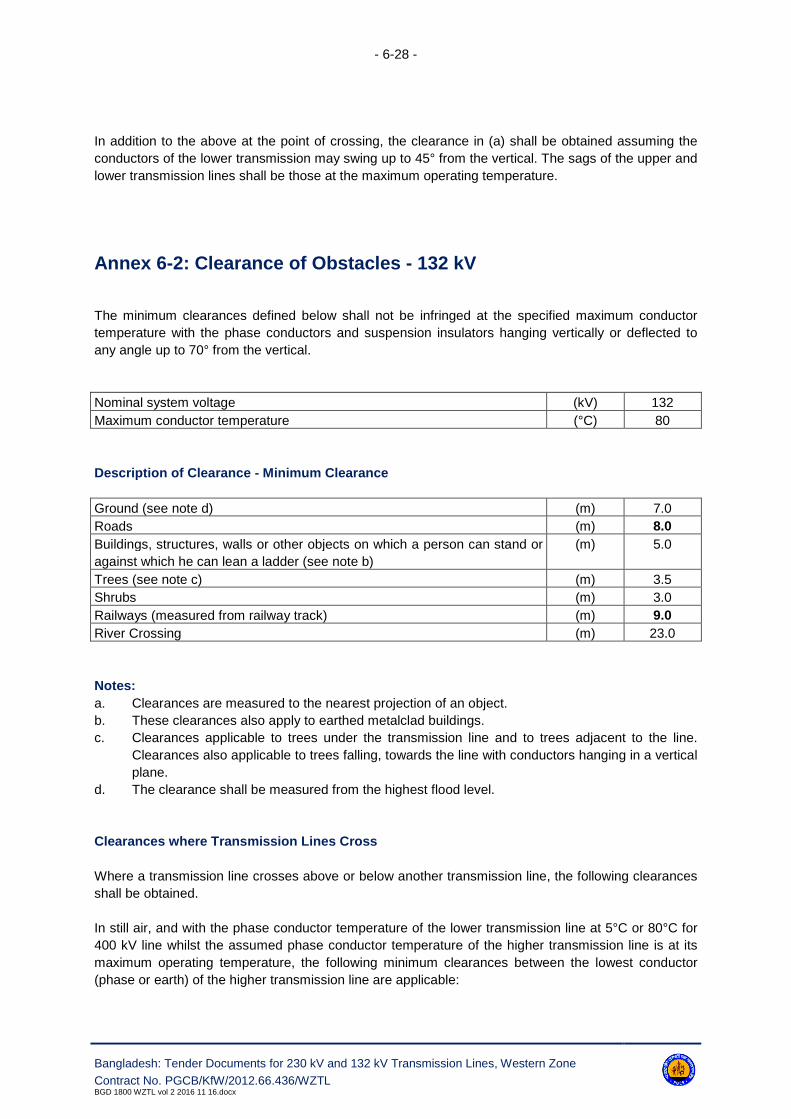
- 6-28 -
Bangladesh: Tender Documents for 230 kV and 132 kV Transmission Lines, Western Zone
Contract No. PGCB/KfW/2012.66.436/WZTLBGD 1800 WZTL vol 2 2016 11 16.docx
In addition to the above at the point of crossing, the clearance in (a) shall be obtained assuming the
conductors of the lower transmission may swing up to 45° from the vertical. The sags of the upper and
lower transmission lines shall be those at the maximum operating temperature.
Annex 6-2: Clearance of Obstacles - 132 kV
The minimum clearances defined below shall not be infringed at the specified maximum conductor
temperature with the phase conductors and suspension insulators hanging vertically or deflected to
any angle up to 70° from the vertical.
Nominal system voltage (kV) 132
Maximum conductor temperature (°C) 80
Description of Clearance - Minimum Clearance
Ground (see note d) (m) 7.0
Roads (m) 8.0
Buildings, structures, walls or other objects on which a person can stand or
against which he can lean a ladder (see note b)
(m) 5.0
Trees (see note c) (m) 3.5
Shrubs (m) 3.0
Railways (measured from railway track) (m) 9.0
River Crossing (m) 23.0
Notes:
a. Clearances are measured to the nearest projection of an object.
b. These clearances also apply to earthed metalclad buildings.
c. Clearances applicable to trees under the transmission line and to trees adjacent to the line.
Clearances also applicable to trees falling, towards the line with conductors hanging in a vertical
plane.
d. The clearance shall be measured from the highest flood level.
Clearances where Transmission Lines Cross
Where a transmission line crosses above or below another transmission line, the following clearances
shall be obtained.
In still air, and with the phase conductor temperature of the lower transmission line at 5°C or 80°C for
400 kV line whilst the assumed phase conductor temperature of the higher transmission line is at its
maximum operating temperature, the following minimum clearances between the lowest conductor
(phase or earth) of the higher transmission line are applicable:

- 6-29 -
Bangladesh: Tender Documents for 230 kV and 132 kV Transmission Lines, Western Zone
Contract No. PGCB/KfW/2012.66.436/WZTLBGD 1800 WZTL vol 2 2016 11 16.docx
System voltage (see Note i) 132 kV
The highest conductor (phase or earth) of the lower transmission line (see Note ii) 4.6 m
Notes:
i) The voltage specified is that for which transmission lines are ultimately designed to operate.
ii) Clearances are determined by the ultimate voltage of either the upper or lower transmission
line, whichever is the greater.
iii) Clearances are determined by the ultimate voltage of the upper/lower transmission line.
In addition to the above at the point of crossing, the clearance in (a) shall be obtained assuming the
conductors of the lower transmission may swing up to 45° from the vertical. The sags of the upper and
lower transmission lines shall be those at the maximum operating temperature.
Annex 6-3: Crossing of Obstacles
Pipeline crossings shall not be at angle to the normal greater than 20 degrees.
Crossings of power supply and communication circuits shall not be at angle to the normal greater than
45 degrees without previous agreement of the Engineer.
Annex 6-4: Geotechnical Investigation
Geotechnical Investigation Level - Frequency
Level 2 Every tower site excluding river crossing and anchor towers and rigid frame tower.
Level 4 At river crossing, anchor towers and rigid frame tower.
Ground water samples shall be taken at every tension tower and all river crossing, anchor tower posi-
tions for chemical analysis.

- 6-30 -
Bangladesh: Tender Documents for 230 kV and 132 kV Transmission Lines, Western Zone - Contract No. PGCB/KfW/2012.66.436/WZTL
BGD 1800 WZTL vol 2 2016 11 16.docx
Annex 6-5: Soil Classification by United Soil Classification System
Major Divisions
(1)
Subdivisions
(2)
USCS
Symbol (3)
Typical names
(4)
Laboratory classification criteria
(5)
Coarse- grained
soils (more than
50% retained on
no. 200 sieve)
Gravels
(more than 50% of
coarse fraction re-
tained on no.4 sieve)
GW Well-graded gravels or gravel-sand mix-
tures, little or no fines.
Less than 5% fines. CU≥4 and 1≤ CC≤3
GP Poorly graded gravels or gravelly sands,
little or no fines.
Less than 5% fines. Does not meet CU and/or
CC criteria listed above.
GM Silty gravels, gravel-sand-clay mixtures. Less than 12% fines. Minus No. 40 soil plots below the A-line.
GC Clayey gravels, gravel-sand-clay mixtures. Less than 12% fines. Minus No. 40 soil plots on or above the A-line.
Sands
(50% or more of
coarse fraction pass-
es no. 4 sieve)
SW Well-graded sands or gravelly sands, little
or no fines.
Less than 5% fines. CC ≥6 and 1≤ CC ≤3.
SP Poorly graded sands or gravelly sands, lit-
tle or no fines.
Less than 5% fines. Does not meet CU and/or
CC criteria listed above.
SM Silty sands, sand-silt mixtures. Less than 12% fines. Minus No. 40 soil plots below the A-line.
SC Clayey sands, sand-clay mixtures. Less than 12% fines. Minus No. 40 soil plots on or above the A-line.
Fine- grained
soils (50% or
more passes the
no. 200 sieve)
Silts and clays
(liquid limit less than
50)
ML Inorganic silts, rock flour, silts of low plas-
ticity
Inorganic soil PI<4 or plots below A-line
CL Inorganic clays of low plasticity, gravelly
clays, sandy clays, etc.
Inorganic soil PI>7and plots on or above A-line
OL Organic silts and organic clays of low plas-
ticity
Organic soil LL (oven dried)/LL (not dried)<0.75
Silts and clays
(liquid limit 50 or
more)
MH Inorganic silts, micaceous silts, silts of high
plasticity
Inorganic soil Plots below A-line
CH Inorganic highly plastic clays, fat clays,
silty clays, etc.
Inorganic soil Plots on or above A-line
OH Organic silts and organic clays of high
plasticity
Organic soil LL(oven dried)/LL(not dried)<0.75
Peat Highly organic PT Peat and other highly organic soils Primarily organic matter, dark in colour, and organic odour
** If 4≤ PI≤7 and PI plots above A-line, then dual symbols (e.g. CL-ML) are required

- 6-31 -
Bangladesh: Tender Documents for 230 kV and 132 kV Transmission Lines, Western Zone - Contract No. PGCB/KfW/2012.66.436/WZTL
BGD 1800 WZTL vol 2 2016 11 16.docx
Annex 6-6: Engineering Documents to be Submitted by the Contrac-tor
Clause Reference Document Description Comment
6.2.8 Route map, Mouza map and profile drawings
6.3.1 Slope stability analysis if specified
6.6.1 Dynamic probe calibration details
6.7 Geotechnical investigation test results
Annex 6-7: Notification and Hold Points
Clause Reference Notification Points Hold Points
6.1 Survey
6.2.8 Route maps, Mouza maps and profile drawings
6.3.1 Geotechnical investigation
6.6.1 Dynamic probe calibration
6.6.1 Level 1
Annex 6-8: Reference Standards
The reference standards and other documents referred to in this Section of the Specification are listed
below:
BS 1377: Method of tests for soils civil engineering purposes
BS 5930: Code of practice for site investigation
ASTM D2488: Standard recommended practice for description of soil visual manual procedure

- 7-1 -
Bangladesh: Tender Documents for 230 kV and 132 kV Transmission Lines, Western Zone
Contract No. PGCB/KfW/2012.66.436/WZTLBGD 1800 WZTL vol 2 2016 11 16.docx
7. Foundations
7.1 Scope
7.1.1 General
7.1.1.1. The type of foundation to be used at each tower position shall be determined from the re-
sults of the geotechnical investigation. The design of the foundation shall be in accordance with the
design parameters and associated criteria detailed in this Specification for tender design purposes, but
finally in accordance with the parameters of the actual geotechnical investigation.
7.1.1.2. The Contractor shall ascertain from the geotechnical investigation that the ground condi-
tions are suitable for each foundation. The level of geotechnical investigation specified is the minimum
level required at site. The Contractor shall undertake all necessary geotechnical investigation for the
foundation design. Any subsidence or failure, due in the opinion of the Engineer to insufficient care
having been taken in either the geotechnical investigation, or installation of the foundations shall be
the Contractor's responsibility.
7.1.1.3. In areas where subsidence is likely to occur the Contractor shall if necessary, carry out
modifications to the tower foundations as agreed by the Engineer. Collar or tie beams between the in-
dividual footings of a tower shall not be used unless specifically authorised by the Engineer. The Con-
tractor shall not be held responsible for failure of tower and foundations arising from adjacent mineral
extraction subsequent to the construction of the transmission line. The Contractor shall, however, be
held liable for any lack of foundation or tower stability due to causes other than subsidence due to
subsequent mineral extraction.
7.1.1.4. The Contractor is responsible for obtaining approval from the Engineer and where appro-
priate statutory regulatory bodies for the type and design of the foundations installed. It should be not-
ed as a general requirement that no site work can commence before such approvals have been ob-
tained. This is a Hold Point.
7.1.2 Method Statement
The Contractor shall submit to the Engineer a comprehensive method statement giving sequential de-
tails of his proposed installation method and include his intended programme. The method statement
shall include but not be limited to the following details:
a. method of excavation. (for all types of foundations) and dealing with water;
b. method of installation of the pile foundations;
c. method of installation of rigid frame / river crossing tower foundations,
d. methods for heating, welding and site bending of reinforcement;
e. method of placing of concrete;
f. method of curing and protecting the concrete;
g. method of backfilling and compacting;
h. Reinstatement of working areas;
i. Quality Control procedures;
j. Site safety procedures.

- 7-2 -
Bangladesh: Tender Documents for 230 kV and 132 kV Transmission Lines, Western Zone
Contract No. PGCB/KfW/2012.66.436/WZTLBGD 1800 WZTL vol 2 2016 11 16.docx
These are Hold Points.
7.1.3 Types and Uses
7.1.3.1. The foundation shall be of open cast type and / or cast in situ piles. Plain cement con-
crete / reinforced cement concrete footing shall be used for all types of normal towers. All four footings
of a tower and their extensions shall be similar for a particular location, except where soil conditions
and / or water table are different at different legs. The total depth of foundations below ground level
shall generally be 3.0 meters. For hard rock type and also where specific site conditions / properties
demand foundations of different depths (lower or higher), the same shall be adopted. Further, for mul-
ti-circuit tower foundations, foundation depth shall be 3.5 meters; for river crossing open cast founda-
tions, the foundation depth shall be more than 3.5 meters.
7.1.3.2. Foundations for towers for different categories of soil conditions shall be selected from
the approved types detailed in Annex 7-1.
7.1.3.3. The Bidder may propose any other proven type of piled foundation instead of drilled shaft
piled foundation except wooden pile. The Bidder shall submit the design of the proposed type of piled
foundation along with detailed design calculation, installation procedure with drawings, quality control
procedure, standards and codes of practices to be followed, Advantages of selecting such type of
piles, etc. with the bid. Reinforced concrete pile caps shall be used for all types of piles. Payments of
all types of foundations shall be on lump-sum basis per tower as per prices quoted in the price sched-
ule.
7.1.3.4. The Contractor or his appointed Subcontractor has to submit relevant documentary evi-
dence that they have previous experience of installing any other type of piled foundation. This is a
Hold Point.
7.1.3.5. Unless specified to the contrary, foundations for angle/terminal towers shall not have dif-
ferent designs for compression and tension footings, but shall be satisfactory for the most adverse
condition of maximum and minimum angles of deviation/entry and with the wind blowing from the most
onerous direction.
7.1.3.6. Foundations for tower body and leg extensions shall be of the same design and where
appropriate utilize the same type of foundation formers as a foundation for the corresponding standard
height tower.
7.2 Design
7.2.1 General
7.2.1.1. During design of towers, the tower reactions on the foundation shall be calculated con-
sidering appropriate maximum simultaneous loading on the towers. During foundation design the ob-
tained reactions shall be multiplied by the strength factors indicated in Annex 8-1, and the resultant
reactions shall be used for foundation design.
7.2.1.2. The material factors are in accordance to Annex 7-3.

- 7-3 -
Bangladesh: Tender Documents for 230 kV and 132 kV Transmission Lines, Western Zone
Contract No. PGCB/KfW/2012.66.436/WZTLBGD 1800 WZTL vol 2 2016 11 16.docx
7.2.1.3. The geotechnical design of the foundation shall be based on accepted codes of practice,
the relevant literature or methods which have been used with satisfactory practical experience by the
Contractor, and agreed by the Engineer.
7.2.1.4. All foundations shall be designed to withstand uplift, settlement and overturning (as ap-
propriate) when subjected to the applied system loading. Allowances shall be made in the foundation
design for hydrostatic pressure where this may occur and the effects of seasonal rains, drying, out,
cyclic loading, wind induced vibration of tower members, and scour.
7.2.2 Geotechnical Parameters
The geotechnical parameters for tendering purposes are provided in Annex 7-2. The Contractor shall
however perform the geotechnical investigation during execution of the contract at each location as
specified in this bidding document. Foundation designs of different towers locations shall be based on
the results of geotechnical investigation done by the Contractor. No extra payment will be made if the
actual soil condition is found to be worse than the soil parameter given in Annex 7-2.
7.2.3 Foundation Structural Design Parameters
Foundation structural design parameters for concrete shall be based upon the recommendations of
BS 8110, except otherwise defined in this Specification.
7.2.4 Stubs
7.2.4.1 Stubs for tower body and leg extensions shall be of the same design as that for a stand-
ard height tower. Only one design of stub shall be permitted for each type of tower, and shall not be
bent or cranked.
7.2.4.2 The thickness of the stub legs shall not be less than the corresponding tower leg mem-
ber.
7.2.4.3 In addition to stubs of normal length, short stubs may be used, provided that provision is
made for the attachment of bolted cleats.
7.2.4.4 Cleats shall be capable of transferring 100 percent of the design uplift working load (not
factored load) and 50 percent of the design compression working load (not factored load) for shearing
and bonding resistance. Two different type of stub design may require for rigid frame foundation and
pile foundation. No extra payments shall be made for such two type of stub.
7.2.5 Holding Down Bolts (Not Used)
7.2.6 Concrete Chimneys
7.2.6.1 Reinforced concrete chimneys shall be designed to withstand the maximum resultant hor-
izontal residual shear component, with due allowance given where appropriate to resultant lateral
(passive) earth pressure of the backfill (assumed to increase linearly with depth).

- 7-4 -
Bangladesh: Tender Documents for 230 kV and 132 kV Transmission Lines, Western Zone
Contract No. PGCB/KfW/2012.66.436/WZTLBGD 1800 WZTL vol 2 2016 11 16.docx
7.2.6.2 No allowance shall be made of the nominal strength of concrete in tension and the stub
shall not be considered as providing any part of the tensile area of reinforcing steelwork.
7.2.6.3 The top of chimney of tower foundation shall be at least 450 mm above nominal ground
level and in case of pile foundation pile cap shall be at least 300 mm below nominal ground level.
7.2.6.4 Foundations for lattice steel tower legs with high hillside shear force, due to certain com-
binations of unequal leg extensions may however differ from those designed for level ground by the
addition of extra reinforcement in the chimney.
7.2.7 Types of Foundation
7.2.7.1 Concrete Pad & Chimney Foundations
7.2.7.1.1. This foundation takes the form of a reinforced concrete flat slab surmounted by a chim-
ney. Alternatively, the slab may be replaced by a truncated concrete pyramid surmounted by a chim-
ney.
7.2.7.1.2. Uplift resistance is assumed to be provided by the mass of soil within the inverted frustum
of a pyramid constructed from the upper edge of the base slabs, or the lower edge for a pyramid.
However, where slabs are cast against undisturbed soil, or undercut, the frustum may be constructed
from the lower edge of the slab base. The angle of the frustum depending on the soil properties, due
consideration shall be taken of buoyancy effects, reduced densities of backfill and design test results.
7.2.7.1.3. For design under compression loading, the area of the base is determined by the design
ground bearing pressure under ultimate loads. In assessing the bearing pressure beneath the founda-
tion, the additional weight of the foundation over that of the displaced soil shall be multiplied by the
appropriate foundation dead weight-factor (Annex 7-1).
7.2.7.1.4. For soft rock a similar type of foundation may be used, where a nominally reinforced con-
crete block is cast-in-situ against the undisturbed rock in conjunction with a nominal undercut at the
lower edge. Uplift resistance is assumed to be resisted by the skin friction developed at the concrete-
rock interface and an inverted frustum in any soil-rock overburden.
7.2.7.2 Piled Foundations
7.2.7.2.1. Pilled shaft foundations shall comprise piles suitably connected below ground level by a
concrete cap. The Contractor shall submit his proposed method of installation and Quality Control pro-
cedures to the Engineer prior to commencing his design. And the Contractor shall submit to the Engi-
neer before start of piling works, a detailed description of the equipment, materials and procedures
that will be used for the piling work. The description shall include equipment specifications, including
catalogue data, manufacturer's published specifications, loading capacities, protective devices and
test apparatus; detailed installation procedures test procedures, as well as references concerning pre-
viously completed piling work. This is a Hold Point.
7.2.7.2.2. The average skin friction or adhesion per unit area of shaft shall be determined from ei-
ther the soil properties measured on samples in a direct shear test or an undrained triaxial compres-
sion test or calculated from SPTs (Standard Penetration Tests), or calculated from CPTs (Cone Pene-
tration Tests). The average value shall be taken over the effective length of the shaft.
- 7-5 -
Bangladesh: Tender Documents for 230 kV and 132 kV Transmission Lines, Western Zone
Contract No. PGCB/KfW/2012.66.436/WZTLBGD 1800 WZTL vol 2 2016 11 16.docx
7.2.7.2.3. Where shear forces are resisted by a cap, an appropriate reduction in the average value
of the skin friction/adhesion shall be taken for the cap design.
7.2.7.2.4. Piled foundations shall comprise either:
(a) Multiple Piled Foundations Using Raked Piles
The pile loads shall be determined by the vector summation of the horizontal and vertical components
of the total reactions at ground level. One multiple pile foundation shall be constructed for each leg,
and since the pile group provides all the lateral stability, no interconnecting ground beam between the
legs are required. Raked piles are not to be used where ground settlement is likely to impose unac-
ceptable bending stresses in the piles.
(b) Multiple Piled Foundations Using Vertical Piles
This type of foundation shall be used when ground settlement is likely to impose unacceptable bend-
ing stresses on raked piles, or where the type of pile cannot be installed raked. In this case lateral sta-
bility shall be provided by the passive resistance of the ground acting on the piles, pile cap and their
interconnecting ground beams where present. In addition to the loading derived from the tower,
ground beams where appropriate shall be designed to accept a specified wheel load.
Ultimate uplift resistance shall be obtained assuming the actual weight of piles, pile caps etc. plus the
guaranteed ultimate uplift resistance of the piles. Allowance shall be made for buoyancy effects. The
minimum component of the uplift resistance provided by the dead weight of the piles and pile caps
should not be less than the value specified in Annex 7-2.
Ultimate compressive loads shall include the superimposed weight of soil; pile caps (and tie beams,
etc.) multiplied by the dead load factor (as per Annex 7-1) and shall be obtained by the guaranteed ul-
timate resistance of the piles.
7.2.7.3 Raft Foundations
Raft foundations for wide based lattice towers shall only be used in areas subject to mining settlement,
or very poor ground where piling is not possible.
7.2.7.4 Rigid Frame Foundation
7.2.7.4.1. Rigid framed foundation, which is adopted at high water level area, shall be consisted of
rigid frame and pile. An example of the foundation is shown in the drawings.
7.2.7.4.2. As for foundation design, foundation shall be designed as a rigid frame to withstand
against uplift load, compression load and horizontal load. The Contractor will consider friction between
pile and soil against uplift load and against compression load, displacement of pile against horizontal
load respectively. Individual footings shall be interconnected by tie beams, which shall be adequate to
resist lateral forces and hydrostatic pressure exerted by the flood water. Allowances shall be made in
the foundation design for hydrostatic pressure and the effects of seasonal rains, and scour.
7.2.7.4.3. In flooding area, the top of chimney concrete of the foundation shall be above the highest
flood level. The Contractor shall confirm the water level and adjust the foundation setting level to meet

- 7-6 -
Bangladesh: Tender Documents for 230 kV and 132 kV Transmission Lines, Western Zone
Contract No. PGCB/KfW/2012.66.436/WZTLBGD 1800 WZTL vol 2 2016 11 16.docx
the requirement. Such foundation site shall be dewatered by pumping or other approved means during
excavation all other necessary arrangements to perform the foundation work in water logged condi-
tion, concrete works and backfilling works. Those costs shall be deemed to be considered in the Con-
tractor's rates.
7.2.7.4.4. Depending on the water height, rigid frame foundation may vary from 2m to 6m. The Con-
tractor shall submit his proposed method of installation and Q.C. procedures to the Engineer prior to
commencing his design. This is a Hold Point.
7.2.7.5 River Crossing Foundations (not used)
7.2.8 Concrete Mix Design
7.2.8.1 The Contractor shall be entirely responsible for the control of the quality of concrete
mixed and placed, in the Works. Before the commencement of any concrete work, the Contractor shall
submit to the Engineer, a complete specification giving details of the materials used, source of supply,
storage and quality control requirements, including preliminary trial mixes and works' tests. This is a
Hold Point.
7.2.8.2 To ensure the durability of the concrete, the requirements specified in Annex 7-4 shall be
adhered to with regard to characteristic strength, minimum cement content and maximum free wa-
ter/cement ratio.
7.2.9 Concrete Cover
7.2.9.1 All structural steelwork and reinforcing including links and stirrups below ground level
shall be completely encased in concrete to ensure a minimum cover as specified in Annex 7-5. Such
cover shall exist from the point of entry into the concrete base to either 450 mm above final ground
level, or to the top of the concrete leg extension.
7.2.9.2 All foundation concrete to a point 450 mm above final ground level shall be undertaken at
the same time and using the same design mix as the main part of the foundation.
7.2.10 Stability Analysis
7.2.10.1 All foundations on slopes greater than 1:4 shall be checked for stability against rotation
where appropriate. Due consideration shall be given to the increased upslope lateral loading of the soil
and the decrease in downhill resistance provided by the soil, when compared to foundations installed
on level ground.
7.2.10.2 Due consideration shall also be taken of any decrease in the uplift resistance of the foun-
dation. Where appropriate, decrease in soil bearing resistance shall also be considered.
7.2.10.3 Where required by the Engineer the overall long-term stability of the slope, including any
proposed slope modifications for constructional purposes e.g. benching shall be considered by an ap-
proved geotechnical consultant appointed by the Contractor.

- 7-7 -
Bangladesh: Tender Documents for 230 kV and 132 kV Transmission Lines, Western Zone
Contract No. PGCB/KfW/2012.66.436/WZTLBGD 1800 WZTL vol 2 2016 11 16.docx
7.2.11 Installation Criteria
The Contractor shall prepare a schedule for construction purposes which clearly indicates the soil
class and type of foundation to be installed at each tower site. The schedule shall show the basis for
selection, taking into account the following items:
a. The results of the geotechnical investigation;
b. The results of any foundation design test;
c. The design criteria;
d. The results of any stability analysis;
e. Those areas which due to the aggressiveness of the sub-soil or sub-soil water a greater mass
of cement per cubic meter of concrete than that specified is required.
The schedule shall be submitted to the Engineer, prior to any foundation installation commencing.
This is a Hold Point.
7.2.12 Design Submission
The Contractor shall submit the following, design submissions to the Engineer:
a. Foundation design calculations;
b. Foundation general arrangement drawing,
c. Slope stability analysis;
d. Bar bending schedule (information only) - if appropriate;
e. Foundation formwork drawings (information only) - if appropriate;
f. Foundation setting template.
Reference should be made to clause 7.1.1 for approval procedures and Hold Point.
7.3 Materials
7.3.1 Concrete
7.3.1.1. All works shall further be carried out in full compliance with all local rules and regulations
and the specification. All materials used in the production of concrete, including all admixtures shall be
in accordance with the requirements of BS 8500 and BS EN 206.
7.3.1.2. Cement shall be either:
a. Portland cement in accordance with BS EN 197-1 strength grade 42.5N;
b. Sulphate resisting Portland cement in accordance with BS 4027 strength
c. grade 42.5N LA;
d. Portland cement combined with a minimum of 25% and a maximum of 40% of pfa. Complying
with BS 3892 Part 1.
7.3.1.3. The maximum particle size of the aggregates shall be so chosen as to be compatible with
mixing, handling, placing, and workability of the concrete.

- 7-8 -
Bangladesh: Tender Documents for 230 kV and 132 kV Transmission Lines, Western Zone
Contract No. PGCB/KfW/2012.66.436/WZTLBGD 1800 WZTL vol 2 2016 11 16.docx
7.3.1.4. Throughout the construction period the quality of concrete mixed at and/or delivered to
Site has to be controlled. Tests shall be carried out in the presence of the Engineer or under the su-
pervision of an approved office for testing of such kind of works. The Contractor shall submit to the
Engineer, test schedules on the following test at least one month prior to commencement.
a. aggregates
b. cement
c. water
d. admixtures and additives
7.3.1.5. In case of placing ready mixed concrete, concrete tests can be replaced by the manufac-
turer's test results.
7.3.1.6. Concreting for pile foundation shall be done through tremie-pipes or equivalent devices to
prevent segregation. For concreting in hot weather, ACI Standard 305R "Hot Weather Concreting"
shall be followed and various means may be employed to lower the temperature of concrete such as:
100. Cooling coarse aggregate with water by sprinkling and shading;
101. Using chilled water;
102. Avoiding the use of the hot cement;
103. Adequately watering of sub-grade, form-work and reinforcement;
104. Intensive moist-curing with potable water of the concrete placed.
7.3.1.7. No admixtures shall be used without approval of the Engineer.
7.3.2 Potential Alkali Reactivity
Aggregate shall not contain any materials that are reactive with alkalis in the aggregate itself, the ce-
ment, the mixing water or in the water in contact with the finished concrete or mortar in amounts suffi-
cient to cause excessive localized or general expansion of the concrete or mortar.
The Contractor may initially assess an aggregate source by testing in accordance with ASTM C289. If
potential reactivity is indicated, then mortar bar tests in accordance with ASTM C227 shall be carried
out and the results shall comply with the limits given in ASTM C33, before use of the aggregate is ap-
proved. Details of the tests shall be submitted to the Engineer. This is a Hold Point.
7.3.3 Reinforcement
7.3.3.1. Unless specified to the contrary high yield steel reinforcement shall be either hot rolled
deformed bars or cold worked deformed bars to BS 4449 and shall have type 2 bond classifications.
7.3.3.2. Mild steel reinforcing shall be plain hot rolled bars to BS 4449. Steel fabric or wrapping
fabric shall be to BS 4483. Where mild steel hot rolled deformed bars are used they shall be generally
in accordance with BS 4449. Reinforcement shall not be manufactured from scrap steel, unless oth-
erwise approved by the Engineer.
7.3.3.3. Where specified fusion bonded epoxy coated reinforcement shall be in accordance with
the requirements of BS ISO 14654 and 14656. Coated reinforcement shall be delivered to site in its
cut and bent form.
- 7-9 -
Bangladesh: Tender Documents for 230 kV and 132 kV Transmission Lines, Western Zone
Contract No. PGCB/KfW/2012.66.436/WZTLBGD 1800 WZTL vol 2 2016 11 16.docx
7.3.3.4. Cropped ends and minor discontinuities of the fusion bonded coating shall be factory
coated using a suitable repair compound formulated in accordance with the manufacturer's specifica-
tion.
7.3.3.5. Where specified fibre enhanced concrete shall contain fibres manufactured from 100 per-
cent virgin polypropylene fibre and designed to achieve maximum distribution and freedom from clus-
tering in the mix.
7.3.4 Reinforcing Bar Coupler
The use of proprietary reinforcing bar couplers to extend reinforcement will be permitted. Details of the
coupler system shall be submitted to the Engineer prior to their use. This is a Hold Point.
7.3.5 Spacers
Dense sand/cement mortar spacing blocks shall be of a low permeability having similar strength, du-
rability and appearance to the surrounding concrete.
Details of patent spacers shall be submitted to the Engineer. This is a Notification Point.
7.3.6 Tying Wire
Tying wire shall be 1.6 mm diameter black annealed mild steel wire for uncoated mild or high yield
steel reinforcement.
Coated bars shall be fixed with plastic coated annealed mild steel tying wire.
7.3.7 Anchor Tendons
All the materials used in the installation of anchor tendons including those used for the grout shall be
in accordance with the requirements of BS 8081 BS EN 1537.
7.3.8 Gabion Baskets
Gabion baskets and mattresses shall be manufactured from cold drawn steel wire. Minimum wire di-
ameter for baskets galvanized to BS EN ISO 1461 shall be 3.0 mm whilst for plastic coated wire gal-
vanized to BS EN 10244-2 shall be 2.7 mm. The minimum radial plastic coating thickness shall be
0.25 mm.
All steel wires shall be electrically welded at every intersection.
7.3.9 Holding Down Bolts (Not used)

- 7-10 -
Bangladesh: Tender Documents for 230 kV and 132 kV Transmission Lines, Western Zone
Contract No. PGCB/KfW/2012.66.436/WZTLBGD 1800 WZTL vol 2 2016 11 16.docx
7.3.10 Piles
If pre-cast concrete or steel piles are used all materials shall be in accordance with the requirements
of the IEC 'Specification for Piling'.
7.3.11 Stubs
Stub steelwork and bolts shall not be inferior to the requirements of clause 8.3.1.
7.3.12 Earthing
7.3.12.1. All mild steel used in the manufacture of earthing rods shall comply with the requirements
of BS EN 10083 etc.: (minimum strength 600 N/m) Earthing rods shall have a minimum diameter of 14
mm.
7.3.12.2. Phosphor-bronze used in the manufacture of earthing rod couplings shall comply with the
requirements of BS 12163 etc.
7.3.12.3. All compression fittings shall be manufactured from electrolytic tough pitch high conduc-
tivity copper, complying with the requirements of BS 13600 and BS EN 1057 and 12449, designation
C101.
7.3.12.4. Earthing conductors shall be in accordance with the following requirements:
a. Copper strip to BS EN 1652, 1653 and 1654, Grade C101 or C102, minimum cross sectional
dimensions 20 mm x 3 mm;
b. Hard drawn copper strand to BS 7884, minimum overall diameter 10.65 (7 x 3.55 mm);
c. Galvanized steel wire to BS 183, minimum overall diameter 9.75 mm (7 x 3.25 mm).
7.4 Workmanship
7.4.1 General
All workmanship shall be in accordance with the requirements of this specification, the appropriate
British Standard and local regulations including the appropriate health and safety requirements. The
Contractor shall comply with all local regulations in respect of safety measures during construction at
site. All local regulations shall also be adhered to. Proper strutting, sheeting and bracing, including re-
arrangement of the installations when necessary, protection of slopes, methods of excavation to re-
duce risk of slides, etc., shall be the Contractor's responsibility to meet the for design and construction
requirements. And workmanship, shall be in accordance with the requirements of ACI 308.1, 301M,
301, 117-117R also.
7.4.2 Site Working Area
The Contractor will be restricted to a specified maximum working area at each tower site. He shall
where required mark this area to clarify boundary lines to other parties. The Engineer shall be kept in-
formed of any activities by others within the working area.
- 7-11 -
Bangladesh: Tender Documents for 230 kV and 132 kV Transmission Lines, Western Zone
Contract No. PGCB/KfW/2012.66.436/WZTLBGD 1800 WZTL vol 2 2016 11 16.docx
The Contractor shall remove all vegetation and other debris from the tower site, which will interfere
with his operation. Vegetation and debris removed from the tower site shall be disposed of outside the
right of way as directed by the Engineer and/or in accordance with local regulations. The Contractor
shall dispose of material and regulate the movement of equipment, and slopes necessary to develop
required loading characteristics shall be maintained, especially in side-hill locations.
7.4.3 Supports of Excavation
7.4.3.1. Excavations shall be adequately supported or formed to ensure stability of the sides and
prevent any damage to the surrounding ground or structures. The design of suitable sheet piling
and/or timbering for the tower of foundation excavation shall be in accordance with the recommenda-
tions of BS 8004 Section 5.
7.4.3.2. When the Contractor is requested, shall submit details of his temporary support to the
Engineer.
7.4.3.3. Excavation material suitable for re-uses, as backfill shall be stored within the site working
area.
7.4.3.4. Excavation top-soil shall be stored separately.
7.4.3.5. Excavated material unsuitable for re-use shall be removed from site to a recognised
dumping area provided by the Contractor, and approved by the relevant authorities.
7.4.3.6. For excavation in cohesive material the final 150 mm above formation level shall only be
removed immediately prior to placing the blinding concrete. This activity shall be programmed to be
carried out on the same day.
7.4.3.7. Excavation shall not be carried out below or adjacent to existing building foundations until
under-pinning and shoring has been completed by the Contractor. Existing structures, foundations,
and services shall be adequately protected or re-routed by the Contractor.
7.4.3.8. The Contractor shall not permit water to accumulate in any excavation unless otherwise
agreed. Any water whether arising from the excavation or draining into shall be drained or pumped to
an approved location well clear of the excavation area in a manner that does not cause erosion, silting
or contamination of existing drains and watercourses. Before the method of ground water lowering is
selected, adequate knowledge of the ground and water conditions has to be obtained from the results
of a soil investigation and/or information, which may be available from the Engineer.
7.4.3.9. The Contractor shall take adequate steps to prevent adjacent ground from being, ad-
versely affected by loss of fines in any de-watering process.
7.4.4 Use of Explosives
The Contractor shall familiarize himself and comply with the laws and local customs concerning the
use, handling and storage of explosives.

- 7-12 -
Bangladesh: Tender Documents for 230 kV and 132 kV Transmission Lines, Western Zone
Contract No. PGCB/KfW/2012.66.436/WZTLBGD 1800 WZTL vol 2 2016 11 16.docx
a) Permission
Explosives shall not be used on the Site without the prior approval of the appropriate Military and Civil
Security Authorities and without prior written approval of the Engineer. This is a Hold Point.
b) Control
The handling of all explosives on site shall be carried out in accordance with local requirements.
c) Approval
The Employer shall be given a minimum of 24 hours' notice of a proposal to use blasting and shall be
given any details they may require concerning the charges and their positions. This is a Notification
Point.
The Employer may regulate, restrict or prohibit blasting, if in their opinion it is necessary to do so for
the safety of persons, property, to limit noise or to safeguard the works.
d) Blasting
For explosives to be allowed in any area of the site, the following and any local requirements shall be
strictly observed.
i) The Contractor will be required to strip overburden and vegetation to expose rock which re-
quires to be blasted;
ii) Where there is any danger of flying rock engineering persons or property, blasting screens
made of approved materials shall be laid over the rock to be blasted, to help prevent dangerous
projection of fragments;
iii) The use of electric detonators will not be permitted within 60 meters of any overhead power
lines;
iv) Delay blasting techniques will be mandatory for all primary blasting with charge limits per delay
period being imposed in order that ground vibration from the blasting can be controlled to a
peak particle velocity of 25 mm/sec. in the vicinity of any structures or installations;
v) All charges prior to firing will be covered with thick gunny sacking and 1.8m squares of steel
mesh weighed down with filled sandbags in order to prevent the projection of rock fragments;
vi) The Contractor will be required to take adequate and effective precautions to prevent debris roll-
ing onto public or private roads and property.
The erection of magazines for storing explosives on site will not be permitted.
7.4.5 Reinforcement
a) Storage
All reinforcement shall be adequately stored to prevent contamination or damage.
b) Cutting and Bending
All reinforcement shall be bent cold unless otherwise permitted by the Engineer. Reinforcement shall
not be straightened or re-bent in a manner which may cause injury to the material. All reinforcement

- 7-13 -
Bangladesh: Tender Documents for 230 kV and 132 kV Transmission Lines, Western Zone
Contract No. PGCB/KfW/2012.66.436/WZTLBGD 1800 WZTL vol 2 2016 11 16.docx
shall be cut and bent in accordance with the requirements of BS 8666 and BS EN ISO 4066. The rein-
forcement shall be clearly identified with securely fixed, durable tags.
c) Fixing
All reinforcement shall be rigidly fixed in position to the concrete cover specified by an approved
means. The Contractor shall be responsible for ensuring that the reinforcement is properly towered
and maintained in position by the adequate use of chairs, spacers and tying wire.
The reinforcement shall be free of all loose rust, scale or contamination of any kind. The reinforcement
shall be inspected/checked after being fixed and no concrete shall be placed around the reinforcement
until such checking/inspection has taken place and concrete permission has been signed by the Engi-
neer.
d) Site Bending
Bending and subsequent straightening of reinforcing bars projecting from the existing concrete shall
be undertaking as follows:
i) Unless noted otherwise on the drawings, the minimum distance from the existing concrete to
the beginning of a bend and the minimum inside diameter of the bend shall be:
Bar DiameterMinimum Distance from Surface
to Beginning of BendMin Inside Bend (mm) Radius
10-24 3 Bar Diameters 3 Bar Diameters
25-32 4 Bar Diameters 3 Bar Diameters
> 32 5 Bar Diameters 5 Bar Diameters
ii) Bars of 10 to 16 mm diameter may be bent once without heating, heating is required for subse-
quent straightening or bending.
Bars of 20 to 32 mm diameter may be bent once and subsequently straightened, heating is re-
quired in all cases.
Bars having a diameter greater than 32 mm may be bent only with the approval of the Engineer,
heating are required in all cases.
iii) Heat shall be applied as uniformly as possible over a length of bar equal to 10 bar diameters.
The centre of the heated length shall be at the centre of the completed bend. The temperature
shall be maintained consistent during bending and straightening operations and shall not ex-
ceed 350°C. Temperature measuring crayons or a contact pyrometer shall be used to deter-
mine the temperature. Care shall be taken to prevent quenching of the heated bars either by
application of water, or by a high volume of air.
iv) Straighten bars shall be visually inspected before and after straightening to determine whether
they are cracked or otherwise damaged. This is a Notification Point.
- 7-14 -
Bangladesh: Tender Documents for 230 kV and 132 kV Transmission Lines, Western Zone
Contract No. PGCB/KfW/2012.66.436/WZTLBGD 1800 WZTL vol 2 2016 11 16.docx
e) Epoxy Coated Bars
i) The Contractor shall take all necessary precautions to minimise damage to the coating during
off-loading, handling and fixing. All equipment used for handling of coated bars shall have pad-
ded contact areas. Coated bars or bundles shall not be dropped or dragged;
ii) Coated bars shall be stored separately to uncoated bars;
iii) Coated bars shall not be cut or bent on site without the prior approval of the Engineer. This is a
Hold Point. Cut ends and any damage to the coating shall be repaired in accordance with
clause 7.5;
iv) Coated bars shall be towered on epoxy coated wire chairs or on chairs of dielectric material.
7.4.6 Concrete Trial Mixes
7.4.6.1 Trial concrete mixes using representative materials shall be carried out under full scale
conditions using the Contractor's proposed method subject to the Engineer's approval. In case of use
of ready mixed concrete, trial mixes shall only be waived, if an earlier proven mix design is used.
7.4.6.2 Testing shall be carried out in accordance with BS EN 12350. Trial mix test specimens
shall be prepared and tested at approved laboratory. Aggregate used in trial mix shall be collected
from the source proposed by the Contractor and approved by the Engineer. The target mean strength
of the trial mixes shall be specified concrete cube strength plus a current margin of 15 N/mm2.
7.4.6.3 The tests shall be carried out on three different days during which the workability will be
recorded and nine cubes made. Among the nine cubes, three will be crushed at seven days; three will
be crushed at fourteen days and the remaining three at twenty eight days. This is a Notification
Point.
7.4.7 Batching
The aggregate and cement shall be proportioned by means of efficient weigh batching machines. The
machine shall be carefully maintained and cleaned and they shall be provided with simple and con-
venient means of checking the weighing mechanism and they shall be checked when required by the
Engineer.
Batch materials, shall be measured out within the following tolerances and shall be discharged into the
mixer without loss.
Cement ± 2 percent of the mass of the cement in the batch.
Aggregate ± 2 percent of the mass of each aggregate in the batch.
Admixtures ± 5 percent of the amount to be added to the batch.
7.4.8 Mixing Concrete by Machine
The concrete is to be mixed in batches in machines which comply with the requirement of BS 1305.
The machines are to ensure that all the concreting materials including the water are thoroughly mixed
together between the time of their deposition in the mixer and before any portion of the mixture is dis-
charged. The machines must be capable of discharging their content while running.

- 7-15 -
Bangladesh: Tender Documents for 230 kV and 132 kV Transmission Lines, Western Zone
Contract No. PGCB/KfW/2012.66.436/WZTLBGD 1800 WZTL vol 2 2016 11 16.docx
7.4.9 Workability
The Contractor shall carry out slump or other workability tests as required during concreting of the
works in order to relate the degree of workability of the mix with the numerical value obtained during
the trial mixes. Concrete slump requirement at the field for the Pile is 125mm-175mm and for the Pad
& Pile cap is 30-75 mm respectively.
7.4.10 Blinding Concrete
Blinding concrete shall be provided under specified foundations to a minimum thickness of 75 mm.
7.4.11 Formwork
7.4.11.1 All formwork shall be accurately constructed to prevent loss of grout and to produce the
correct foundation shape. Formwork shall be sufficiently strong to withstand the pressures arising from
the concrete during placing and compaction and shall be capable of removal without undue disturb-
ance to the concrete.
7.4.11.2 All form-work and moulds shall be of such tight construction that slurry cannot flow out at
the joints during pouring and compaction. If required, joints shall be sealed with foam rubber strips.
7.4.11.3 Formwork shall be retained in position after concreting for a minimum period of 48 hours.
7.4.12 Placing and Compacting
7.4.12.1. Concrete shall normally be discharged from the delivery vehicle within two hours after the
time of loading at the ready mix plant in accordance with the requirements of BS 8500 and BS EN
206. With the Engineer's approval these periods may be exceeded with the use of a suitable retarder
and/or plasticizer, provided that there is no change in the quality of the concrete. Concrete must at all
times -have the desired workability and characteristics at the point of placing. Any concrete which no
longer meets this requirement shall be removed from site.
7.4.12.2. Placing by pump, conveyor or pneumatic method shall be subject to approval by the En-
gineer. There shall not be any loss of quality in the concrete, nor harmful effects to the works by such
methods. Concrete pumps shall be operated by mechanically applied pressure and shall produce a
continuous stream of concrete without air pockets.
7.4.12.3. Where pumps are used the velocity of discharge shall be regulated, by suitable baffles or
hoppers where necessary to prevent segregation or damage and distortion of the reinforcement, em-
bedded items and formwork, caused by impact.
7.4.12.4. When pumps are used on large or complicated pours a standby pump shall be provided.
7.4.12.5. Precautions shall be taken to avoid depositing water or grout in the Works during starting
up operations, or in flushing, or clearing the pipeline. The pipeline shall pass its own length of concrete
in not more than 20 minutes.
7.4.12.6. Chutes used to deliver concrete shall not be sloped so as to cause segregation of the
mix.

- 7-16 -
Bangladesh: Tender Documents for 230 kV and 132 kV Transmission Lines, Western Zone
Contract No. PGCB/KfW/2012.66.436/WZTLBGD 1800 WZTL vol 2 2016 11 16.docx
7.4.12.7. Concrete shall be fully, compacted by vibration or other approved means and shall com-
pletely fill the shutter. Immersion vibrators shall be inserted in such a manner and at intervals as will
ensure the satisfactory uniform compaction of the concrete. The vibrator shall penetrate the full depth
of the layer and where the underlying layer of concrete has not initially set, they shall enter and re-
vibrate the layer to ensure that succeeding, layers are well bonded together. Withdrawal of vibrators
shall be such as to prevent the formation of voids. Piles of concrete within the formwork shall not be
moved by immersion of the vibrator, nor shall segregation be caused by over vibration. Undue laitance
or leakage through the formwork shall be avoided. It shall be fully, worked around reinforcement and
other embedded items which shall not be disturbed. The Contractor shall provide standby vibrators.
7.4.12.8. The Contractor shall maintain records of daily returns of the quantity, concrete mix and
location within the Works of all concrete placed. These shall be forwarded to the Engineer when re-
quested.
7.4.13 Joints
7.4.13.1. Construction joints shall be made across planes of minimum shear and away from planes
of maximum bending moments. Vertical construction joints shall be made against properly constructed
stop boards firmly fixed and holed where necessary to pass reinforcement. To ensure bond between
old and new concrete at construction joints, surfaces of the cast (old) concrete shall be cleaned of all
defective concrete, latency, oil, grease, dirt, loose concrete, etc. and shall properly be roughened by
chipping, hammering or other techniques to expose the aggregates and provide sufficient key for the
two layers.
7.4.13.2. The pad and chimney (for pad and chimney type foundations) shall normally be cast in
one operation without construction joints. Where the formation of a joint is unavoidable the surface
against which the fresh concrete is to be placed shall be prepared in accordance with Clause 6.12 of
BS 8110: Part 1. This is a Notification Point.
7.4.13.3. Construction joints in anchor or pile caps, mono-block and raft foundations shall be treat-
ed in similar manner to that described above. When the embedded reinforcement is insufficient to
transmit the required design load, additional reinforcement in the form of 'starter' bars shall be provid-
ed. No construction joints are permitted in cast-in-situ concrete piles, drilled shaft or side bearing
foundations.
7.4.14 Curing and Protection
Curing and protection shall start immediately after the compaction of the concrete and shall ensure
adequate protection from:
a) Premature drying out, particularly by solar radiation and wind;
b) Leaching out by rain and flowing water;
c) Rapid cooling during the first few days after placing;
d) High internal thermal gradients;
e) Vibration and impact which may disrupt the concrete and interfere with its bond to the rein-
forcement or other embedded items.
Where curing compounds are used to protect exposed surfaces from solar radiation and improve
moisture retention, they shall be subject to the approval of the Employer. This is a Hold Point.
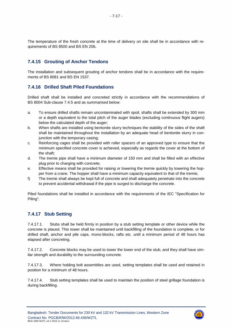
- 7-17 -
Bangladesh: Tender Documents for 230 kV and 132 kV Transmission Lines, Western Zone
Contract No. PGCB/KfW/2012.66.436/WZTLBGD 1800 WZTL vol 2 2016 11 16.docx
The temperature of the fresh concrete at the time of delivery on site shall be in accordance with re-
quirements of BS 8500 and BS EN 206.
7.4.15 Grouting of Anchor Tendons
The installation and subsequent grouting of anchor tendons shall be in accordance with the require-
ments of BS 8081 and BS EN 1537.
7.4.16 Drilled Shaft Piled Foundations
Drilled shaft shall be installed and concreted strictly in accordance with the recommendations of
BS 8004 Sub-clause 7.4.5 and as summarised below:
a. To ensure drilled shafts remain uncontaminated with spoil, shafts shall be extended by 300 mm
or a depth equivalent to the total pitch of the auger blades (excluding continuous flight augers)
below the calculated depth of the auger;
b. When shafts are installed using bentonite slurry techniques the stability of the sides of the shaft
shall be maintained throughout the installation by an adequate head of bentonite slurry in con-
junction with the temporary casing;
c. Reinforcing cages shall be provided with roller spacers of an approved type to ensure that the
minimum specified concrete cover is achieved, especially as regards the cover at the bottom of
the shaft;
d. The tremie pipe shall have a minimum diameter of 150 mm and shall be filled with an effective
plug prior to charging with concrete;
e. Effective means shall be provided for raising or lowering the tremie quickly by towering the hop-
per from a crane. The hopper shall have a minimum capacity equivalent to that of the tremie;
f) The tremie shall always be kept full of concrete and shall adequately penetrate into the concrete
to prevent accidental withdrawal if the pipe is surged to discharge the concrete.
Piled foundations shall be installed in accordance with the requirements of the IEC "Specification for
Piling".
7.4.17 Stub Setting
7.4.17.1. Stubs shall be held firmly in position by a stub setting template or other device while the
concrete is placed. This tower shall be maintained until backfilling of the foundation is complete, or for
drilled shaft, anchor and pile caps, mono-blocks, rafts etc. until a minimum period of 48 hours has
elapsed after concreting.
7.4.17.2. Concrete blocks may be used to tower the lower end of the stub, and they shall have sim-
ilar strength and durability to the surrounding concrete.
7.4.17.3. Where holding bolt assemblies are used, setting templates shall be used and retained in
position for a minimum of 48 hours.
7.4.17.4. Stub setting templates shall be used to maintain the position of steel grillage foundation is
during backfilling.

- 7-18 -
Bangladesh: Tender Documents for 230 kV and 132 kV Transmission Lines, Western Zone
Contract No. PGCB/KfW/2012.66.436/WZTLBGD 1800 WZTL vol 2 2016 11 16.docx
7.4.18 Backfilling of Foundations
7.4.18.1. Backfilling shall be compacted in 300 mm layers to achieve a bulk density of 1.6 t/m3, or
the value assumed in the design analysis (if this is less than 1.6 t/m3).
7.4.18.2. Commencement of backfilling shall be a Notification Point.
7.4.18.3. During backfilling, the side sheeting to the excavation shall, where possible, be progres-
sively withdrawn such that the toe of the sheeting is never more than 600 mm below the surface of the
compacted material.
7.4.18.4. Extreme care shall be taken by the Contractor during compaction to ensure that the foun-
dation is not damaged nor caused to move out of position. During the placing of backfill the hole shall
be kept free from water. All temporary timbering and all decomposable material shall be removed from
the excavations prior to backfilling.
7.4.18.5. Refilling around the pile head pits shall be carried out only after all works within the exca-
vations have been inspected and approved by the Engineer.
7.4.18.6. The Contractor shall select the compaction plant most suitable for achieving the required
bulk density. Acceptable methods of compaction shall include, but not be restricted to, the use of vi-
brating plate compactor or diesel hand operated vibrating Wacker plate. The actual method of com-
paction selected will depend on the type of material to be compacted and the difficulty in accessing
areas within the excavation.
7.4.18.7. Backfilling of the directly embedded pole annulus shall be undertaken using crushed rock
aggregate in accordance with BS EN 12620, with a nominal maximum size of 40 mm.
7.4.19 Site Clearance
As soon as possible at each tower site, backfilling should be completed, surplus soil removed and the
site cleared at the Contractor's cost. Final site clearance normally carried out at the same time as fit-
ting of anti-climbing guards and danger and notice plates, shall be undertaken without delay. The Con-
tractor shall be responsible for compacting and re-levelling ground to the original surface level and
gradient. Where agreed by the Engineer a percentage of the spoil may be disposed of by local spread-
ing and the balance, if any shall be removed from site.
7.4.20 Reinstatement of Working Areas
7.4.20.1. Reinstatement of all working, access and storage areas shall be the responsibility of the
Contractor.
7.4.20.2. A programme for reinstatement works shall be submitted to and approved by the Engi-
neer prior to the issue of the taking over certificate.
7.4.20.3. Reinstatement where specified shall include all necessary topsoil preparation, hydro-
seeding and the planting of shrubs and trees to a standard at least equal to the condition of the site
prior to construction. The sequence of work shall be such as to ensure establishment of all species
and the age and state of growth of plants shall be such as to ensure successful replanting at site.

- 7-19 -
Bangladesh: Tender Documents for 230 kV and 132 kV Transmission Lines, Western Zone
Contract No. PGCB/KfW/2012.66.436/WZTLBGD 1800 WZTL vol 2 2016 11 16.docx
7.4.20.4. All such work shall be completed to the satisfaction of the Engineer and the relevant
regulatory authorities.
7.4.21 Site Stabilisation
7.4.21.1. Where foundations are installed on sloping or unstable ground the Contractor shall be re-
sponsible for ensuring the stability of the area and the safety of the public, all to the satisfaction of the
Engineer and local regulatory authorities.
7.4.21.2. Stabilisation shall be achieved by approved methods such as retaining walls, buttresses,
sprayed concrete, rock bolts, dowels or gabion baskets / mattresses.
7.4.21.3. Site assembly of gabion baskets and mattresses shall be carried out in accordance with
the manufacturer's instructions. Gabions shall be placed in position prior to filling and secured to ad-
joining gabions with lacing wire. Filling material shall be between 100 and 150 mm; 90 percent of the
fill to be retained on a 100 mm ring. The fill shall be tightly packed with no apparent voids, and shall be
overfilled by 25-50 mm to allow fat settlement lids shall be laced immediately after filling.
7.4.21.4. Where necessary to prevent erosion and as stipulated by the Engineer, or the appropriate
authority, surface drainage channels shall be provided; surge chambers stopped ends and sublets
shall be formed as required. Where surface vegetation has been removed from sloping ground such
that erosion could occur the area shall be reinstated by planting of grasses using hydro-seeding meth-
ods or band sprigging.
7.4.22 Site Protection
Where specified tower legs or foundations are in areas open to vehicle access, the Contractor shall
install barriers of a type approved by the Engineer to prevent vehicle coming into contact with the tow-
er or foundation.
7.4.23 Earthing
7.4.23.1. The maximum tower footing resistance with earthwires disconnected shall be 5 ohms.
Earthing shall be provided with all diagonal legs of each tower (type A) as shown in enclosed drawing.
If additional earthing is required, additional earthing conductor shall be attached to the tower at the
earthing holes specified and shall be sufficiently buried to prevent accidental excavation (type B). The
amount of earthing conductor to be buried or earthing rods installed (type C) will be dependent upon
achieving the required footing resistance.
7.4.23.2. The excavation for the earthing conductor shall be 400 mm wide and not less than 800
mm deep in cultivated land where required by the Employer. The earthing conductor shall be laid at a
depth of approximately 700 mm, being placed centrally in the trench. The trench shall be backfilled
with a suitable medium.
7.4.23.3. The connection between the additional earthing conductor and tower leg shall be by ap-
proved thermo-weld joints.

- 7-20 -
Bangladesh: Tender Documents for 230 kV and 132 kV Transmission Lines, Western Zone
Contract No. PGCB/KfW/2012.66.436/WZTLBGD 1800 WZTL vol 2 2016 11 16.docx
7.4.23.4. Where necessary in areas of high resistance 90 mm diameter holes shall be drilled along
the tower diagonal, each having, an earthing rod surrounded by a Bentonite/ sodium carbonate mix
(type D). The holes depth will depend on the resistance of the soil. The earth rod shall comprise
standard rods coupled together and connected back to the tower leg.
7.4.23.5. For towers within 150 m of a substation and connected to the substation earthing system,
no additional earthing will normally be required.
7.4.23.6. All metallic fence gates within the right of way shall be electrically bounded to the fences.
7.5 Protective Treatment
7.5.1 Galvanising
All stub steelwork, pole sections and holding down bolts shall be protected by hot-dipped galvanising
to comply with the requirements of BS EN ISO 1461.
7.5.2 Epoxy Coal Tar Paint
All directly embedded pole sections, steel pile and caisson sections, guy anchor rods shall be protect-
ed by two coats of epoxy coal tar paint. For steel pile sections, this treatment shall only apply to the
initial 50mm below final -round level.
7.5.3 Epoxy Coated Reinforcement
Coating, damaged during transit handling or fixing shall be repaired only with the approved repair
compound supplied, to ensure compatibility with the Fusion Bonded Epoxy Coating. All repairs shall
be carried out strictly in accordance with the manufacturer's instructions.
When the extent of the coating damage on any metre length of bar exceeds 1% of the surface area,
the bar shall be rejected. This is a Notification Point.
7.5.4 Tower Steelwork and Stub-Concrete Interface
7.5.4.1. After curing has been completed all exposed concrete above ground level and 300 mm
below ground level shall be coated with coal tar epoxy coating applied by either conventional spraying
or brushing to give a minimum dry film thickness of 300 μm. The surface of the concrete shall be al-
lowed to cure for at least 28 days prior to surface preparation unless otherwise agreed with the Engi-
neer. After adequate curing all surface laitance, dirt and other contaminants shall be removed. Prior to
the application of the coating, cracks in the concrete greater than 2mm in width and surface irregulari-
ties, including blow holes, with a depth greater than 10mm, shall be filled with a proprietary fairing coat
compatible with the coating system. The surface of the substrate shall be prepared in accordance with
the coating manufacturers recommendations. Primers where necessary, shall be obtained from the
same manufacturer as the top coat.

- 7-21 -
Bangladesh: Tender Documents for 230 kV and 132 kV Transmission Lines, Western Zone
Contract No. PGCB/KfW/2012.66.436/WZTLBGD 1800 WZTL vol 2 2016 11 16.docx
7.5.4.2. All tower steelwork below the maximum anticipated flood level shall be protected by coal
tar epoxy coatings. All steelwork to a minimum height of 3m above ground level shall be protected by
factory application with the remainder applied on site, including the stub above concrete level.
7.5.4.3. For factory application the galvanised steel members should be blast cleaned to a mini-
mum SA2 standard BS 7079 using a fine grade mineral blasting medium. The coating shall be applied
by either conventional spraying or brushing to give a minimum dry-film thickness of 300 μm. Prior to
application, the coating applicator shall submit procedures for coating, application and quality control
measures for approval by the Engineer. This is a Hold Point.
7.5.4.4. The method of application of the coating system shall be in accordance with the approved
procedures and manufacturer's instructions. The Contractor shall ensure that the proposed coverage
rates will enable the specified minimum dry film thickness of each coat to be attained. Wet film thick-
ness gauges shall be used to check the thickness of the applied coating.
7.5.4.5. Each application of the coating shall be generally free from surface defects, particularly
cratering, pin-holing, ravelling, sagging, bittiness, dry spray and cissing. The finished system shall
have a uniform appearance.
7.5.4.6. For site application the same procedure shall be adopted except that use of an 'etch pri-
mer' instead of blast cleaning on site will be permitted. The 'etch primer' must be obtained from the
same supplier as the coating and applied strictly in accordance with the manufacturer's instructions in-
cluding the cleaning and decreasing of the tower steelwork on site.
7.5.5 Earthing Material
Steel earth rods shall be clad with 99.9 percent electrolytic pure copper molecularly bonded to the
steel, with a minimum thickness of 0.35 mm. The earthing conductor at the ground interface and at the
connection to the tower shall be protected against corrosion.
7.5.6 Protection of Buried Steelwork
Where it is necessary for tower steelwork to be buried, it shall be buried not more than 1.0 m and shall
be protected by an approved medium e.g. mastic impregnated tape or bitumastic paint. Details of the
proposed materials, application and quality control procedure shall be submitted to the Engineer. This
is a Hold Point.

- 7-22 -
Bangladesh: Tender Documents for 230 kV and 132 kV Transmission Lines, Western Zone
Contract No. PGCB/KfW/2012.66.436/WZTLBGD 1800 WZTL vol 2 2016 11 16.docx
7.6 Quality Control
7.6.1 General
Type, sample and routine tests shall be undertaken on all materials used in the construction of the
foundations, and where appropriate on the complete foundations, or parts of the complete foundation
in accordance with the requirements of this specification.
7.6.2 Bentonite Slurries
Bentonite slurries used to tower the sides of the drilled shaft foundations shall be prepared and con-
trolled in accordance with the recommendations of BS 8004 Clause 6.5.3.8 and as summarised below:
a. Bentonite shall be supplied in accordance with the oil companies materials association specifi-
cation No. DFCP4;
b. After mixing, with clean fresh water the fully hydrated bentonite slurry shall have a density of
less than 1. 10 g/ml, a viscosity as measured by the Marsh cone between 30 s to 90 s and a 10
minute gel strength in the range of 1.4 to 10 N/m2;
c. Immediately prior to concreting, the density of the slurry at a level of 200 mm above the bottom
of the shaft shall be less than 1.5 g/ml;
d. The pH value of the slurry shall be maintained within the range of 9.5 to 12.
7.6.3 Reinforcement
All reinforcement shall be supplied from approved suppliers, complete with the appropriate test certifi-
cates in respect of the test requirements of BS 4449 or BS 4483 as appropriate. Copies of these certif-
icates shall be made available to the Engineer upon request. Where test certificates are not available
the Contractor shall arrange for the tests to be undertaken in accordance with the specified standards.
7.6.4 Inspection Prior to Concreting
The Contractor shall give the requisite period of notice to the Engineer of his intention to commence
any concreting and shall submit at the same time a record of his inspection of completed preparatory
works. This shall include all works related to the fixing of reinforcement. This is a Notification Point.
7.6.5 Trial Mixes
A trial mix will be approved when the requirements of BS 8500 and BS EN 206 are met. Copies of the
trial mix test results shall be submitted to the Engineer.
7.6.6 Workability
7.6.6.a The Contractor shall carry out slump or other workability tests as required during concret-
ing of the works in order to relate the degree of workability of the mix with the numerical value ob-
tained during the trial mix.

- 7-23 -
Bangladesh: Tender Documents for 230 kV and 132 kV Transmission Lines, Western Zone
Contract No. PGCB/KfW/2012.66.436/WZTLBGD 1800 WZTL vol 2 2016 11 16.docx
7.6.6.b Slump tests shall be carried out in accordance with the procedure laid down in
BS EN 12350-1. A slump test will be accepted as complying with the Specification when the results
are within the following limits: ±25 mm.
7.6.6.1 Works Cubes
7.6.6.1.1. Compliance with the specified characteristic strength shall be based on tests made on
cubes at 28 (twenty eight) days. Cubes shall be made, cured and tested in accordance with BS EN
12350-1. Samples of Concrete shall be taken at the point of discharge from the delivery point.
7.6.6.1.2. Unless otherwise directed by the Engineer, one set of cubes shall be prepared for each
pile. For Pile caps, beams, Chimney, one set for every 6 cubic meter or part thereof for each day of
concreting shall be prepared. Each set consists of four cubes, one for 7 days testing and two for 28
days testing shall be taken.
7.6.6.1.3. Each set of cubes shall be accompanied by a certificate noting the details required by
BS EN 12350-1.
7.6.6.1.4. Cubes shall be tested in accordance with BS EN 12350-1 to determine the density and
characteristic strength as follows:
a. One cube shall be tested at seven days to provide an early indication as to whether the twenty
eight day strength is likely to be achieved;
b. Two cubes shall be tested at twenty eight days; the average strength shall be deemed the test
results;
c. One cube shall be held in reserve for further testing, if required.
7.6.6.1.5. The test report shall provide information in accordance with BS EN 12350-1.
7.6.6.1.6. Concrete shall be assumed to have achieved its characteristic strength when, at twenty
eight days, the conditions specified in BS 8500 and BS EN 206 are met.
7.6.6.1.7. Copies of the test reports shall be made available to the Engineer on a regular basis.
This is a Notification Point.
7.6.6.1.8. The Employer will consider whether the concrete in the Works represented by cubes fall-
ing below the limits lay down can be accepted, and he may order that any or all of the following, ac-
tions shall be taken:
i) Penetration resistance or surface hardness tests;
ii) The drilling of test cylinders in the concrete and testing the samples to destruction by compres-
sion;
iii) The cutting out and replacement of such volumes at their discretion which they consider to be
defective.
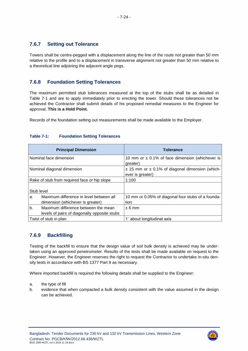
- 7-24 -
Bangladesh: Tender Documents for 230 kV and 132 kV Transmission Lines, Western Zone
Contract No. PGCB/KfW/2012.66.436/WZTLBGD 1800 WZTL vol 2 2016 11 16.docx
7.6.7 Setting out Tolerance
Towers shall be centre-pegged with a displacement along the line of the route not greater than 50 mm
relative to the profile and to a displacement in transverse alignment not greater than 50 mm relative to
a theoretical line adjoining the adjacent angle pegs.
7.6.8 Foundation Setting Tolerances
The maximum permitted stub tolerances measured at the top of the stubs shall be as detailed in
Table 7-1 and are to apply immediately prior to erecting the tower. Should these tolerances not be
achieved the Contractor shall submit details of his proposed remedial measures to the Engineer for
approval. This is a Hold Point.
Records of the foundation setting out measurements shall be made available to the Employer.
Table 7-1: Foundation Setting Tolerances
Principal Dimension Tolerance
Nominal face dimension 10 mm or ± 0.1% of face dimension (whichever is
greater)
Nominal diagonal dimension ± 15 mm or ± 0.1% of diagonal dimension (which-
ever is greater)
Rake of stub from required face or hip slope 1:100
Stub level
a. Maximum difference in level between all
dimension (whichever is greater)
10 mm or 0.05% of diagonal four stubs of a founda-
tion
b. Maximum difference between the mean
levels of pairs of diagonally opposite stubs
± 6 mm
Twist of stub in plan 1˚ about longitudinal axis
7.6.9 Backfilling
Testing of the backfill to ensure that the design value of soil bulk density is achieved may be under-
taken using an approved penetrometer. Results of the tests shall be made available on request to the
Engineer. However, the Engineer reserves the right to request the Contractor to undertake in-situ den-
sity tests in accordance with-BS 1377 Part 9 as necessary.
Where imported backfill is required the following details shall be supplied to the Engineer:
a. the type of fill
b. evidence that when compacted a bulk density consistent with the value assumed in the design
can be achieved.

- 7-25 -
Bangladesh: Tender Documents for 230 kV and 132 kV Transmission Lines, Western Zone
Contract No. PGCB/KfW/2012.66.436/WZTLBGD 1800 WZTL vol 2 2016 11 16.docx
7.6.10 Foundation Tests - General
7.6.10.1. When requested by the Engineer full scale foundations tests both design and routine /
proof shall be undertaken on all types of foundations.
7.6.10.2. Tests shall unless specified otherwise be undertaken in accordance with IEC 61773.
7.6.10.3. When design tests are required, the sites selected shall be representative of the geo-
technical conditions throughout the length of the transmission line, in which the Contractor proposes to
install that type of foundation.
7.6.10.4. The Contractor shall submit to the Engineer the following information:
a. Details of the test sites, including all geotechnical parameters;
b. Details of the proposed test equipment, test layout, measuring equipment, test procedure and
the test program. This a Hold Point.
c. On completion of the design tests the requisite number of test reports shall be submitted to the
Engineer.
7.6.10.5. The ultimate resistance of the foundation shall unless otherwise specified be determined
from the lesser of:
i) the resistance equivalent to a temporary displacement of 25 mm or,
ii) the resistance equivalent to a permanent displacement of 10 mm.
7.6.10.6. Reports on pile testing shall be submitted to the Engineer and shall contain, among oth-
ers, the following information:
a. Layout of test equipment and description
b. Pile identification, diameter and length
c. Sketch of soil conditions and ground water location
d. Complete records of level, load cell and dial gauge readings against date and time throughout
the test in a tabulation
e. Graphs of load and settlement/heave versus time
f. Graphs of settlement/heave versus load
g. Remarks concerning any unusual occurrences during the loading of the pile.
h. Test reports on integrity testing of piles shall include clear sample diagrams of acceptable sig-
nals for comparison purpose, as well as sample graphs indicating defects or doubts on the in-
tegrity of the pile.
7.6.10.7. The Engineer will decide on completion of tests and evaluations whether the test piles
shall be left in place or shall be extracted. No extra payment will be made for the extraction of test
piles.
7.6.11 Concrete Pad & Chimney Foundation - Tests
Unless otherwise specified only design uplift tests on pad and chimney foundations shall be undertak-
en. The Contractor shall give the Engineer the requisite period of notice prior to undertaking the tests.
This is a Hold Point.
- 7-26 -
Bangladesh: Tender Documents for 230 kV and 132 kV Transmission Lines, Western Zone
Contract No. PGCB/KfW/2012.66.436/WZTLBGD 1800 WZTL vol 2 2016 11 16.docx
7.6.12 Piled Foundation - Tests
Unless specified to the contrary, design uplift and compression tests on piled foundations (service
piles selected by Employer) shall be undertaken. The Contractor shall give the Engineer testing pro-
cedure for approval and the requisite period of notice prior to undertaking the tests. This is a Hold
Point.
The tested pile shall be deemed to comply with its specified ultimate load when, after the load is held
for at least 30 minutes, the following criteria are satisfied:
a. The displacement at the head of the pile is less than 25 mm or
b. The movement of the head of the pile shall be slowing down and less than 0.25 mm/hour;
c. The displacement at the head of the pile after all loads are removed (after 10 minutes) is less
than 10 mm.
7.6.13 Integrity Testing
7.6.13.1. Integrity tests shall be performed on drilled shaft concrete piled foundations selected by
Employer for checking the uniformity, continuity and length of such piles using the acoustic pulse echo
method shall be undertaken by a specialist subcontractor appointed by the Contractor. Details of prac-
tical experience of the subcontractor along with details of the test equipment, procedure of testing,
presentation of test data/results shall be submitted to the Engineer before the implementation of actual
field work. The integrity test shall be done at least one pile of each leg. The actual method of perform-
ing the tests and the interpreting the results shall be subject to the Engineer's approval. This is a Hold
Point.
7.6.13.2. The Contractor shall give the Engineer the requisite period of notice prior to undertaking
the tests. This is a Notification Point.
7.6.13.3. The results of the integrity testing shall be made available to the Engineer upon request.
7.6.14 Earthing Resistance Test
7.6.14.1. Earth electrical resistance tests shall be undertaken at each tower prior to the erection of
the earthwire. The Contractor shall give the Engineer the requisite period of notice prior to undertaking
the tests. This is a Notification Point.
7.6.14.2. On sites subject to seasonal variations in the rainfall, or the level of the water table and
sites requiring special earthing arrangements additional earth resistance tests shall be carried out at
intervals to establish the effects on the resistance of such seasonal variations.
7.6.14.3. The method of measurement and equipment to be used shall be subject to the approval
of the Engineer. This is a Hold Point.
7.6.14.4. The results of the earth resistance tests both initial and final i.e. after additional earthing
has been installed shall be forwarded to the Engineer.

- 7-27 -
Bangladesh: Tender Documents for 230 kV and 132 kV Transmission Lines, Western Zone
Contract No. PGCB/KfW/2012.66.436/WZTLBGD 1800 WZTL vol 2 2016 11 16.docx
7.6.15 Protective Coatings
7.6.15.1. Where protective coatings are applied to buried tower steelwork or to exposed concrete
surfaces, appropriate routine tests to demonstrate the quality of application shall be undertaken.
7.6.15.2. The Contractor shall submit to the Engineer his routine test proposals. This is a Hold
Point.
7.6.15.3. The Contractor shall give the Engineer the requisite period of notice prior to undertaking
the tests. This is a Notification Point. The results of the tests shall be made available to the Engineer
upon request.
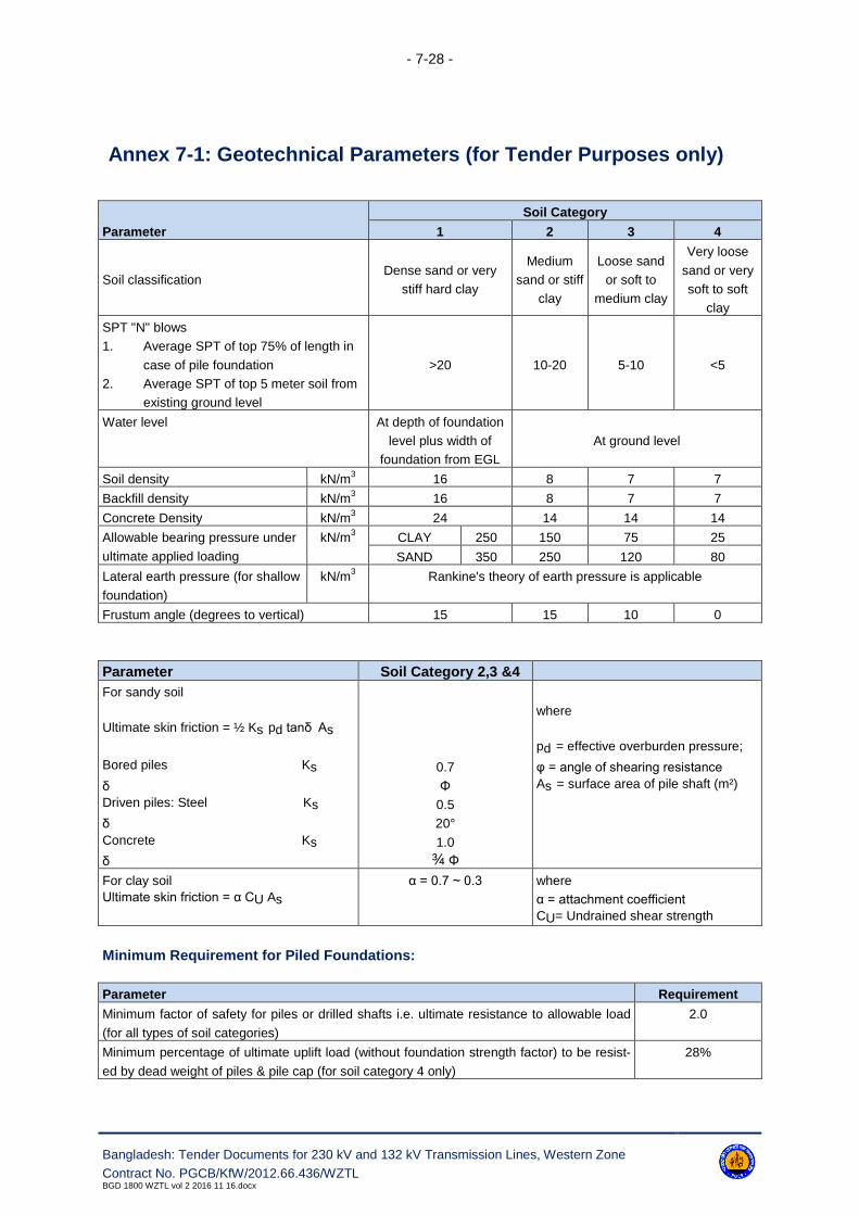
- 7-28 -
Bangladesh: Tender Documents for 230 kV and 132 kV Transmission Lines, Western Zone
Contract No. PGCB/KfW/2012.66.436/WZTLBGD 1800 WZTL vol 2 2016 11 16.docx
Annex 7-1: Geotechnical Parameters (for Tender Purposes only)
Parameter
Soil Category
1 2 3 4
Soil classificationDense sand or very
stiff hard clay
Medium
sand or stiff
clay
Loose sand
or soft to
medium clay
Very loose
sand or very
soft to soft
clay
SPT "N" blows
1. Average SPT of top 75% of length in
case of pile foundation
2. Average SPT of top 5 meter soil from
existing ground level
>20 10-20 5-10 <5
Water level At depth of foundation
level plus width of
foundation from EGL
At ground level
Soil density kN/m3
16 8 7 7
Backfill density kN/m3
16 8 7 7
Concrete Density kN/m3
24 14 14 14
Allowable bearing pressure under
ultimate applied loading
kN/m3
CLAY 250 150 75 25
SAND 350 250 120 80
Lateral earth pressure (for shallow
foundation)
kN/m3
Rankine's theory of earth pressure is applicable
Frustum angle (degrees to vertical) 15 15 10 0
Parameter Soil Category 2,3 &4
For sandy soil
Ultimate skin friction = ½ Ks pd tanδ As
Bored piles Ks
δ
Driven piles: Steel Ks
δ
Concrete Ks
δ
0.7
Φ
0.5
20°
1.0
¾ Φ
where
pd = effective overburden pressure;
φ = angle of shearing resistance
As = surface area of pile shaft (m²)
For clay soil
Ultimate skin friction = α CU As
α = 0.7 ~ 0.3 where
α = attachment coefficient
CU= Undrained shear strength
Minimum Requirement for Piled Foundations:
Parameter Requirement
Minimum factor of safety for piles or drilled shafts i.e. ultimate resistance to allowable load
(for all types of soil categories)
2.0
Minimum percentage of ultimate uplift load (without foundation strength factor) to be resist-
ed by dead weight of piles & pile cap (for soil category 4 only)
28%

- 7-29 -
Bangladesh: Tender Documents for 230 kV and 132 kV Transmission Lines, Western Zone
Contract No. PGCB/KfW/2012.66.436/WZTLBGD 1800 WZTL vol 2 2016 11 16.docx
Annex 7-2: Concrete Mix Parameters
Grade of Concrete Cement Type
Minimum Cement
Content kg/m³
Maximum Free Water /
Cement Ratio
C30 Ordinary Portland Cement
(OPC)
370 0.5
C30 Pozzolanic Portland
Cement (PPC)
370 0.5
C30 Sulphate Resistant Portland
Cement (SRC)
As per BSEN 197-1 CEMII/B-V
Notes:
1. Maximum nominal aggregate size 20 mm.
2. For installation of drilled shaft piled foundations using bentonite slurries minimum cement con-
tent shall be increased to 400 kg/m³.
3. Slump range for cap and chimney is 50 mm to 100 mm and for pile 150 mm to 200 mm.
* If required as per soil and ground water test report.
Annex 7-3: Concrete Cover
Reinforcement
(mm)
Stub Steelwork or Reinforcing Designed as
'Stub' Steelwork (mm)
100 150
Annex 7-4: Engineering Documents to be Submitted by the Contrac-tor
Clause Reference Documents Description Comment
7.1.2 Installation method statement
7.2.1 Contractor's proposed c.o.v.
7.2.1 Temporary tower details If requested
7.2.7.2 Drilled foundation method statement
7.2.7.2 River crossing tower foundations method statement
7.2.7.4 Installation method statement and QC procedures -
rigid frame foundations
7.2.8 Concrete specification
7.2.11 Installation criteria
7.2.12 Design submissions
7.3.2 Potential alkali reactivity - test results
7.3.4 Reinforcing bar couplers
7.3.5 Spacers Details of system
7.3.12 Concrete daily returns If requested

- 7-30 -
Bangladesh: Tender Documents for 230 kV and 132 kV Transmission Lines, Western Zone
Contract No. PGCB/KfW/2012.66.436/WZTLBGD 1800 WZTL vol 2 2016 11 16.docx
Clause Reference Documents Description Comment
7.4.20 Working area reinstatement Programme of work
7.5.6 Protection of buried steelwork Quality control proposals
7.6.3 Reinforcement - test certificates If requested
7.6.4 Inspection prior to concreting Inspection record
7.6.5 Trial mixes - test results
7.6.6.1 Works cubes - test results
7.6.8 Foundation incorrect setting, Remedial Measure
7.6.8 Foundation setting out-records
7.6.9 Imported backfill - detail
7.6.10 Foundation tests - test proposal
7.6.10 Foundation tests - test results
7.6.10 Anchor foundation - routine test records If requested
7.6.10 Integrity testing - test records If requested
7.6.14 Earth resistance tests - test records
7.6.15 Protective coating - routine tests proposals
7.6.15 Protection coatings - test records If requested
Annex 7-5: Notification and Hold Points
Clause Reference Notification Points Hold Points
7.1.1 Foundation design
7.1.2 Method statement
7.2.7.2 Piled foundations
7.2.7.4 Rigid frame foundations
7.2.8 Concrete mix design
7.2.11 Installation criteria
7.2.12 Design submissions
7.3.2 Potential alkali reactivity
7.3.4 Reinforcing bar couplers
7.3.5 Spacers
7.4.4 Use of explosives Use of explosives
7.4.5 Straightening of bars Epoxy bars site cutting
7.4.6 Concrete trial mixes
7.4.13 Joints
7.4.14 Curing compounds
7.4.18 Backfilling
7.5.3 Epoxy coating repair Steelwork and stub - concrete interface
7.5.4 Tower steelwork
7.5.6 Protection of buried steel work
7.6.4 Inspection prior to concreting Foundation setting remedial measure
7.6.6.1 Concrete cube tests Foundation test program
7.6.8 Anchor foundations - suitability test
7.6.10 Anchor foundations - design test
7.6.11 Concrete pad & chimney foundations -
tests

- 7-31 -
Bangladesh: Tender Documents for 230 kV and 132 kV Transmission Lines, Western Zone
Contract No. PGCB/KfW/2012.66.436/WZTLBGD 1800 WZTL vol 2 2016 11 16.docx
Clause Reference Notification Points Hold Points
7.6.12 Piled foundations - design tests
7.6.13 Integrity testing Integrity testing - test proposals
7.6.14 Earthing resistance tests Earth resistance tests -test proposals
7.6.15 Integrity testing Protective coating - test proposals
Annex 7-6: Reference Standards
The reference standards and other documents referred to in this section of the specification are listed
below:
BS EN 197-1: Specification for Portland cement
BS 183: Specification for general purpose galvanised steel wire strand
BS EN 10244-2: Specification for testing zinc coating on steel wire & for quality requirements
BS EN ISO 1461: Specification for hot dip galvanised coatings on iron & steel articles
BS EN 12620: Specification for aggregates from natural sources of concrete
BS EN 10083,4,5: Specification for wrought steel for mechanical and allied engineering purposes
BS EN 10088,
BS EN 10089,
BS 1305:
Specification for batch type concrete mixers
BS 1377: Method of tests for soils for civil engineering purposes, Part 9: In-situ Tests
BS EN 12350-1: Testing concrete - Method of sampling fresh concrete on site
BS EN 12390-3: Method of determining compressive strength of concrete
BS EN 13600: Specification for high conductivity copper tubes for electrical purposes
BS EN 1652, 3, 4: Specification for rolled copper and copper alloys, sheet, strip and foil
BS EN 1057: Specification for copper and copper alloys. Tubes
BS EN 12449
BS EN 12163, 4, 7:
Specification for wrought steel for mechanical and applied engineering purpos-
es.
BS 3643: ISO Metric screw threads
BS 3892: Pulverised - fuel ash
Part 1: Specification for pulverised - fuel ash for use Alith Portland cement
BS 4027: Specification for sulphate - resisting Portland cement
BS 4190: Specification for ISO metric black hexagon bolts, screws and nuts
BS 4449: Specification for carbon steel bars for the reinforcement of concrete
BS 8666: Specification for scheduling, dimensioning, bending & cutting of steel rein-
forcement for concrete
BS EN ISO 4066
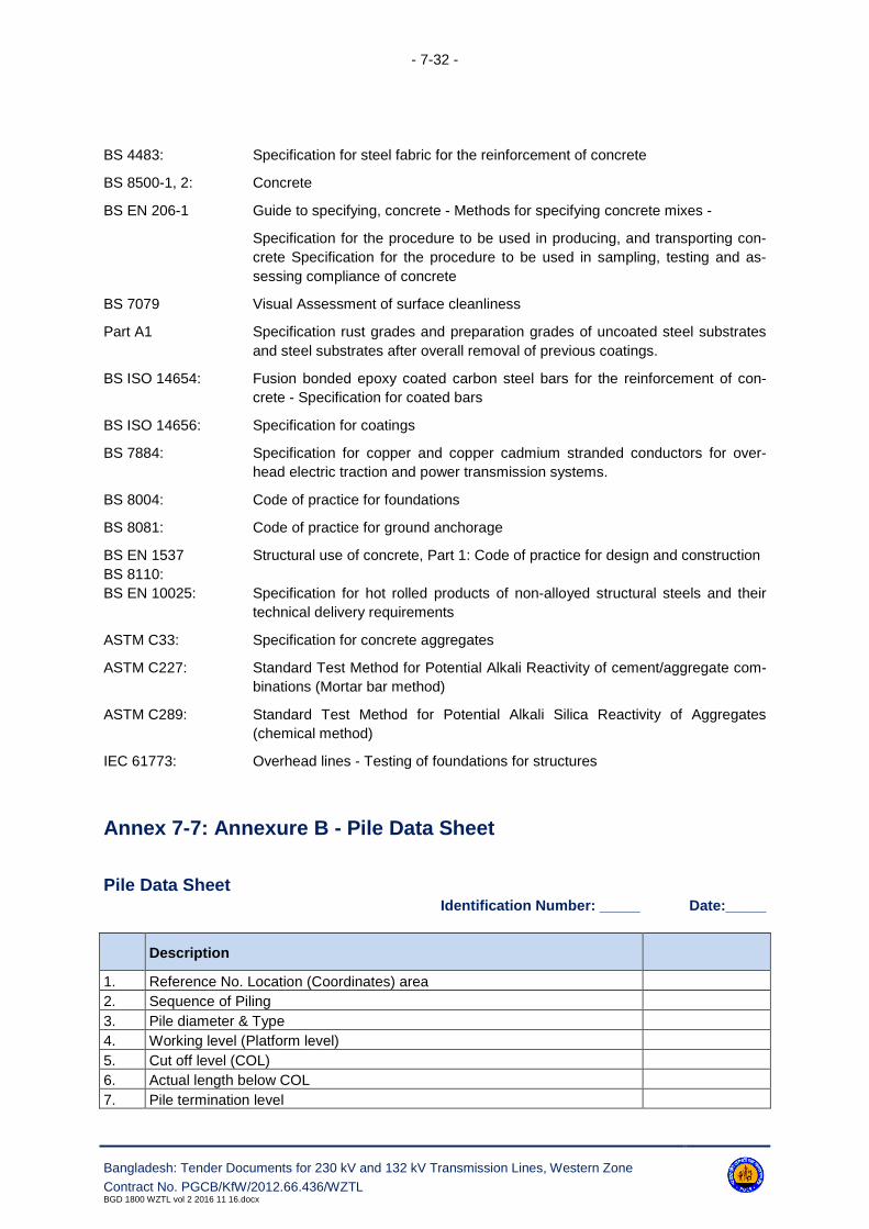
- 7-32 -
Bangladesh: Tender Documents for 230 kV and 132 kV Transmission Lines, Western Zone
Contract No. PGCB/KfW/2012.66.436/WZTLBGD 1800 WZTL vol 2 2016 11 16.docx
BS 4483: Specification for steel fabric for the reinforcement of concrete
BS 8500-1, 2: Concrete
BS EN 206-1 Guide to specifying, concrete - Methods for specifying concrete mixes -
Specification for the procedure to be used in producing, and transporting con-
crete Specification for the procedure to be used in sampling, testing and as-
sessing compliance of concrete
BS 7079 Visual Assessment of surface cleanliness
Part A1 Specification rust grades and preparation grades of uncoated steel substrates
and steel substrates after overall removal of previous coatings.
BS ISO 14654: Fusion bonded epoxy coated carbon steel bars for the reinforcement of con-
crete - Specification for coated bars
BS ISO 14656: Specification for coatings
BS 7884: Specification for copper and copper cadmium stranded conductors for over-
head electric traction and power transmission systems.
BS 8004: Code of practice for foundations
BS 8081: Code of practice for ground anchorage
BS EN 1537
BS 8110:
Structural use of concrete, Part 1: Code of practice for design and construction
BS EN 10025: Specification for hot rolled products of non-alloyed structural steels and their
technical delivery requirements
ASTM C33: Specification for concrete aggregates
ASTM C227: Standard Test Method for Potential Alkali Reactivity of cement/aggregate com-
binations (Mortar bar method)
ASTM C289: Standard Test Method for Potential Alkali Silica Reactivity of Aggregates
(chemical method)
IEC 61773: Overhead lines - Testing of foundations for structures
Annex 7-7: Annexure B - Pile Data Sheet
Pile Data SheetIdentification Number: _____ Date:_____
Description
1. Reference No. Location (Coordinates) area
2. Sequence of Piling
3. Pile diameter & Type
4. Working level (Platform level)
5. Cut off level (COL)
6. Actual length below COL
7. Pile termination level

- 7-33 -
Bangladesh: Tender Documents for 230 kV and 132 kV Transmission Lines, Western Zone
Contract No. PGCB/KfW/2012.66.436/WZTLBGD 1800 WZTL vol 2 2016 11 16.docx
Description
8. Top of finished concrete level
9. Date and time of start and completion of boring
10. Depth of Ground water table in the vicinity
11. Type of strata at pile tip
12. Method of boring operation
13. Details of drilling mud as used:
14. Freshly supplied mud liquid limit
– sand content
– density
– marsh viscosity
– Swelling index pH value
15. Contaminated mud
– density
– sand content
16. SPT, N values in soil (from the nearest borehole).
17. Chiselling if any, from ... m to ... m.
18. Date and time of start and completion of concreting
19. Method of placing concrete
20. Concrete quantity:
21. Actual
22. Designed
23. Ref. Number of test cubes
24. Grade and slump of concrete
25. Results of test cubes
26. Reinforcement details:
27. Main Reinforcement
– Stirrups: Type
– No.
– Diameter
– Depth
28. No.
29. Diameter
30. Spacing
31. Any other information regarding constructions, delay and other interruption
to the sequence of work.
Note: The above details are required to be furnished by the Contractor before starting the installation
work.

- 8-1 -
Bangladesh: Tender Documents for 230 kV and 132 kV Transmission Lines, Western Zone
Contract No. PGCB/KfW/2012.66.436/WZTLBGD 1800 WZTL vol 2 2016 11 16.docx
8. Towers
8.1 Scope
8.1.1. The scope includes design, testing, fabrication, supply and erection of towers on the basis of
tender specification.
8.1.2. The contract comprises design of new towers for completely new 230 kV double circuit lines on-
ly. For all other transmission line the existing PGCB’s design shall be used.
8.1.3. The all 132 kV towers and 230 kV towers for line / line out are not to be designed by the
Contractor. Employer shall provide structural/erection drawings, available shop drawings & Bill of Ma-
terials of all type of transmission line towers and its extensions, special towers as required to the Con-
tractor after placement of award, in sequence, suiting the project requirement.
8.1.4. The copies of proto type load tested towers structural drawings and available shop drawings
will be provided to the Contractor by the Employer upon request by the Contractor. However, if the
Contractor needs to prepare any additional structural and shop drawings or make any correction of ex-
isting drawings, that have to be prepared by the Contractor without any additional cost.
8.1.5. Bidders are requested to inspect the available drawings in the Design Dept. of PGCB to sat-
isfy them regarding the extent of available drawings. Bidders are required to propose the tower mate-
rials from a manufacturer who will use the same material standard as mentioned in the tower draw-
ings.
8.1.6. The scope also include all types of tower accessories like phase plate, circuit plate (where ever
applicable), number plate, danger plate, anti-climbing device, Bird guard, ladder (wherever applicable),
resting platform (wherever applicable) etc.
8.1.7. To minimize the impact of the towers in terms of rights of way and foot prints, the following tow-
ers are proposed for 132 kV and 230 kV D/C overhead lines: wide (normal) base with approximate di-
mensions for standard height suspension towers of maximum 5.00 m x 5.00 m in case of 132 kV lines
and 6.50 m x 6.50 m in case of 230 kV lines.
8.1.8. It has to be noted that the narrow base towers will require larger foundations as well as extra-
large main members for the equivalent load; in this respect for both Lots was specified towers with
wide (normal) base.
8.1.1 Classes of Towers
Reference shall be made to Annex 8-2 for the classes of tower required.
8.1.2 Designation of Tower Types
Reference shall be made to Annex 8-3 for the designation and use of the different tower types.

- 8-2 -
Bangladesh: Tender Documents for 230 kV and 132 kV Transmission Lines, Western Zone
Contract No. PGCB/KfW/2012.66.436/WZTLBGD 1800 WZTL vol 2 2016 11 16.docx
8.1.3 Standard Height Towers
All standard height towers are those designed to support the conductors at the defined clearance
above designated ground under the specified ultimate limit state system loading assuming such tow-
ers are at the same level on level ground and at the standard span apart. The Standard span length is
shown in Annex 8-5.
Unless specified to the contrary, after taking account of the length of the insulator set all standard
height towers shall be arranged so that the point of attachment or suspension of the phase conductors
above the ground shall be the same for all tower types.
8.1.4 Extensions
8.1.4.1 Where specified each type of tower shall be designed to allow for variations in height.
Towers with any specified combination of extensions to the standard height tower, shall be capable of
carrying all required phase conductors, earthwires, insulator sets and fittings under the specified sys-
tem loading.
8.1.4.2 Reference shall be made to the Annex 8-4 for the range and type of extensions required.
Tower with different leg extensions shall be used as per requirement of the route.
8.1.4.3 Where individual leg extensions are specified for lattice steel towers they shall be directly
interconnectable and fully compatible with the basic tower body and all specified body extensions.
8.1.5 Span Criteria
8.1.5.1 The span lengths specified in Annex 8-5 shall be deemed to be the horizontal distance
between centre lines of adjacent support. When a span in excess of the specified maximum span is
unavoidable, advice on the application should be obtained from the Engineer.
8.1.5.2 All angle towers when used with the corresponding maximum angles of deviation and all
intermediate type towers shall be used so that the sum of the two adjacent spans stated in Annex 8-5
is not exceeded, provided that no single span length exceeds the specified maximum. Designs shall
allow for the adjacent spans of the maximum specified length with one of the spans at the maximum
allowed for a single span.
8.1.5.3 Section type tower may be used at straight line positions where necessary for uplift condi-
tions or for sectioning and tensioning of the phase conductors and earthwires in a straight run of
transmission line route.
8.1.5.4 Angle towers shall be suitable for minimum weight spans combined with maximum wind
span through the full angular range of line deviations for which the angle towers are designed.
8.1.6 Minimum Conductor Weight at Intermediate Tower
The total weight supported by any intermediate tower suspension insulator set shall not be less than
the specified percentage (see Annex 8-5) of the total weight of the corresponding phase conductors in
the two adjacent spans. This condition shall apply under the specified loading conditions.

- 8-3 -
Bangladesh: Tender Documents for 230 kV and 132 kV Transmission Lines, Western Zone
Contract No. PGCB/KfW/2012.66.436/WZTLBGD 1800 WZTL vol 2 2016 11 16.docx
8.1.7 Angle Towers
For angle towers at the mean angle of deviation, the mean horizontal separation between circuits shall
not be less than that of an intermediate type support.
For bundled phase conductors the phase conductor attachment points on each crossarm/gantry shall
be arranged to ensure that the nominal horizontal separation between sub-conductors at the tension
joint (dead end), is not reduced by more than 25 mm.
8.1.8 Terminal Towers
Terminal towers shall provide the corresponding separation at the specified line entry. Additional
phase conductor attachment points shall be provided at the specified angles of entry. Additional
crossarms for down-leads or for use in junction arrangements with full phase tension shall be provided
when specified.
8.2 Design
8.2.1 General
8.2.1.1. Towers shall have the general arrangements and configurations shown in the drawings
included with the Specification. They shall be designed to resist the specified system loading taking in-
to consideration the required strength coordination factors. Clearances between live parts and sup-
porting steelwork and between the phase conductors and ground or other obstacles shall be as speci-
fied.
8.2.1.2. All tower designs shall be such as to facilitate inspection, painting, maintenance, repairs
and operation with the continuity of supply being the prime consideration.
8.2.1.3. The design shall be such that the number of different parts shall be as few as possible to
facilitate transport, erection and inspection. The maximum weight of the heaviest single member
should be limited to that within the normal lifting capability of the proposed erection equipment.
8.2.1.4. Main leg members of lattice steel towers shall be formed of the maximum single lengths
appropriate to the body or leg extensions, and shall not without the Engineer's approval, incorporate
additional spliced sections.
8.2.1.5. For lattice steel towers a fully triangulated system of bracings shall preferably be adopted.
If full triangulation is not adopted, the overall stability and secondary bending, stresses must be con-
sidered in the design.
8.2.1.6. Where fabrication processes employed adversely affect the material properties, or intro-
duce zones of high stress concentration the overall design of the structures shall take such factors into
account.
8.2.1.7. Crossarms shall be so arranged that they can be disconnected in the plane of the longi-
tudinal face of the tower without disturbing any members forming part of the tower body.

- 8-4 -
Bangladesh: Tender Documents for 230 kV and 132 kV Transmission Lines, Western Zone
Contract No. PGCB/KfW/2012.66.436/WZTLBGD 1800 WZTL vol 2 2016 11 16.docx
8.2.1.8. All panels below the proto type test tower height must be of K-braced type.
8.2.2 Attachments to Towers
The attachment of phase conductors, earthwires and erection/maintenance brackets shall be under-
taken as follows:
(a) Intermediate Lattice Steel Towers
i) Suspension insulator set and earthwire attachments shall be of an approved swivel or shackle
arrangement;
ii) Adjacent to and either side of all suspension insulators set attachment points, additional
maintenance points shall be provided, capable of resisting the specified construction and
maintenance (C&M) load;
iii) Adjacent to the earthwire suspension set attachment point, an additional maintenance point
shall be provided, capable of resisting the specified C&M load;
iv) At each tower body crossarm connection point (bottom chord level) maintenance plates / brack-
ets shall be provided for the attachment of rigging blocks, capable of resisting the specified
C&M load;
v) Where it is proposed to erect complete sections of the tower by crane or helicopter then perma-
nent lifting points shall be provided.
(b) Angle/Tension Lattice Steel Tower
i) Tension insulator set attachments shall be of an approved swivel or shackle arrangement;
ii) Adjacent to and either side of all tension insulator set attachment points, additional maintenance
points shall be provided, capable of resisting the specified C&M loading. The additional mainte-
nance points shall provide the necessary mountings for stringing and maintenance equipment;
iii) Adjacent to all tension insulator set attachment points, a vertical maintenance attachment point
shall be provided, capable of resisting either the specified C&M loads or that imposed by the
use of a conductor stringing platform;
iv) Adjacent to the earthwire tension set attachment point, an additional maintenance point shall be
provided, capable of resisting the specified C&M loads;
v) At each tower body crossarm connection point (bottom chord level) maintenance plates / brack-
ets shall be provided for the attachment of rigging, blocks, capable of resisting the specified
C&M loads.
(c) River Crossing Towers
i) Suspension insulator set and earthwire attachments shall be of an approved swivel or shackle
arrangement;
ii) Adjacent to and either side of all suspension insulators set attachment points, additional mainte-
nance points shall be provided, capable of resisting the specified construction and maintenance
(C&M) load;
iii) Adjacent to the earthwire suspension set attachment point, an additional maintenance point
shall be provided, capable of resisting the specified C&M load;
iv) At each tower body crossarm connection point (bottom chord level) maintenance plates / brack-
ets shall be provided for the attachment of rigging blocks, capable of resisting the specified
C&M load;

- 8-5 -
Bangladesh: Tender Documents for 230 kV and 132 kV Transmission Lines, Western Zone
Contract No. PGCB/KfW/2012.66.436/WZTLBGD 1800 WZTL vol 2 2016 11 16.docx
v) Where it is proposed to erect complete sections of the tower by crane or helicopter then perma-
nent lifting points shall be provided.
(d) Anchor Tower
i) Tension insulator set attachments shall be of an approved swivel or shackle arrangement;
ii) Adjacent to and either side of all tension insulator set attachment points, additional maintenance
points shall be provided, capable of resisting the specified C&M loading. The additional mainte-
nance points shall provide the necessary mountings for stringing and maintenance equipment;
iii) Adjacent to all tension insulator set attachment points, a vertical maintenance attachment point
shall be provided, capable of resisting either the specified C&M loads or that imposed by the
use of a conductor stringing platform;
iv) Adjacent to the earthwire tension set attachment point, an additional maintenance point shall be
provided, capable of resisting the specified C&M loads;
v) At each tower body crossarm connection point (bottom chord level) maintenance plates / brack-
ets shall be provided for the attachment of rigging blocks, capable of resisting the specified
C&M loads.
All tower general arrangement drawings and/or erection diagrams shall clearly indicate the safe work-
ing, load capacities of all maintenance points.
8.2.3 Stubs
Stubs for the standard height tower, tower body and leg extensions shall be of the same design. Un-
less specified to the contrary only one design of stub shall be permitted for each type of tower and the
stubs shall be identical for all four legs. Two different type of stub design may require for rigid frame
foundation and pile foundation. No extra payments shall be made for such two type of stub. For details
of the cleat design, reference shall be made to Clause 7.2.4.
The thickness of the stub leg members shall not be less than the corresponding tower leg members.
8.2.4 Design Criteria
Unless otherwise mentioned in the bidding documents, towers shall be designed in accordance with
ASCE 74-2009.
Wind speed (Failure Limit), weather load factor and exposure category shall be considered as men-
tioned in Annex 8-1.
Loading Conditions Wind Coincident Temperature Design Aspect
Normal Condition (DL) 50% of ULS 50 C Electrical Clearance of
structure (PFC)
Normal Condition (DL) 15.6 m/s 50 C Electrical Clearance of
structure (LIC)
Normal Condition (DL) 100% of FL 5 C
Structure designHigh Intensity Wind Condition 100% of FL 5 C
Security Condition 50% of FL 5 C

- 8-6 -
Bangladesh: Tender Documents for 230 kV and 132 kV Transmission Lines, Western Zone
Contract No. PGCB/KfW/2012.66.436/WZTLBGD 1800 WZTL vol 2 2016 11 16.docx
Loading Conditions Wind Coincident Temperature Design Aspect
Safety condition 15.6 m/s 5 C
DL - Damage Limit, FL - Failure Limit, PFC - Power Frequency Clearance,
LIC - Lighting Impulse Clearance.
8.2.5 Load Case and Load Combination
8.2.5.1 Normal Conditions
The towers shall be designed for the following loads considered to be applicable simultaneously.
a) Vertical Loads
Dead weight of tower, weight of insulators and all other fittings, actual dead weight of conductor,
earthwire and OPGW of specified weight span lengths in Annex 8-5. Vmax for maximum weight span
with load factor 1.25 and Vmin for minimum weight span with load factor 0.9 shall be considered.
Description Load Factor
maximum weight span 1,25
minimum weight span 0,9
b) Transverse Loads
Transverse load due to wind (wind angle 0°, 22.5°, 45°, 67.5° and 90°) on earthwire/OPGW, conduc-
tor, tower members, insulator and all other fittings and transverse component of maximum working
tension of earthwire/OPGW & conductor due to maximum horizontal deviation angle of line. Load fac-
tor for horizontal tension of earthwire/OPGW & conductor shall be considered 1.25.
c) Longitudinal Loads
For suspension towers 3 % and for angle towers 10% of conductor or earthwire/OPGW ultimate ten-
sile strength shall be considered as unbalanced longitudinal load. For terminal tower, maximum work-
ing tension of conductor shall be considered as unbalanced longitudinal load.
8.2.5.2 Special Normal Condition
a) Eccentric Loads
Towers shall be checked for eccentric loading caused by the conductors and earthwire/OPGW strung
on one side of the tower. In checking the tower for this kind of loading the loads mentioned above for
vertical, transverse and longitudinal loads shall be considered for three phase conductors and earth-
wire/OPGW on one side of the tower in addition to wind on tower and weight of tower.
For terminal towers, torsion loads caused by the unbalanced longitudinal working tension due to one
circuit conductors and earthwire/OPGW strung shall be considered.
b) High Intensity Local Wind Loadings

- 8-7 -
Bangladesh: Tender Documents for 230 kV and 132 kV Transmission Lines, Western Zone
Contract No. PGCB/KfW/2012.66.436/WZTLBGD 1800 WZTL vol 2 2016 11 16.docx
High intensity local wind is required to be considered by applying wind at 0°, 22.5°, 45°, 67.5° and 90°
on tower body. A load factor of 2.0 on wind pressure is required to be considered for this case. It shall
be assumed that there is no wind on conductor.
8.2.5.3 Security Loading
The towers shall be designed for the following loads considered to be applicable simultaneously.
a) Vertical Loads
Dead weight of tower, weight of insulators and all other fittings, actual dead weight of conductor,
earthwire and OPGW of specified weight span lengths in Annex 8-5 (Vmax for maximum weight span
and Vmin for minimum weight span). Vmax for maximum weight span with load factor 1.25 and Vmin for
minimum weight span with load factor 0.9 shall be considered.
b) Transverse Loads
Transverse load due to wind (50% of ULS wind at angle 0°) on earthwire/OPGW, conductor, tower
members, insulator and all other fittings and transverse component of maximum working tension of
earthwire/OPGW & conductor due to maximum horizontal deviation angle of line. Load factor for hori-
zontal tension of earthwire/OPGW & conductor shall be considered 1.25.
c) Longitudinal Loads
For intact point, unbalanced tension is similar to normal condition.
For broken point, unbalanced longitudinal tension shall be considered as per criteria given below:
Tower Type
Conductor
Tension Residual Static Load Factor
Load
Factor Broken Wire Assumption
Suspension/
Heavy suspen-
sion Conductor ten-
sion at security
condition
String Length Factor
1.251 earthwire or 1 phase (all sub-
phase) is broken
< 1m 1.0
1m< but < 2m 0.7
> 2m 0.6
Angle tower 1.0 1.25
1 earthwire and 1 phase (all sub-
phase) or 2 phase broken (all
sub-phase) on the same side are
broken
8.2.5.4 Safety Loading
a) Structure Erection
The specified construction and maintenance loading shall be applied to all phase conductor and
earthwire/OPGW attachment points in the combinations stated.

- 8-8 -
Bangladesh: Tender Documents for 230 kV and 132 kV Transmission Lines, Western Zone
Contract No. PGCB/KfW/2012.66.436/WZTLBGD 1800 WZTL vol 2 2016 11 16.docx
Where appropriate that loading and/or their individual components shall also be applied to the corre-
sponding maintenance points e.g. the vertical component shall be applied to vertical maintenance at-
tachment points, whilst the longitudinal is distributed to the horizontal maintenance plates.
All members with an inclination of 40 degrees to 90 degrees to the vertical, shall be checked for the ef-
fects of point loading of 1.5kN at its most onerous position. No other loading shall be considered under
this condition.
It is the Contractor's responsibility to consider all constructional loading due to his proposed method of
tower erection and conductor stringing. Where necessary, any additional loading due to these meth-
ods shall be considered in the design of the tower and especially the specified maintenance, lifting or
attachment points. Under these conditions a minimum load factor of 1.5 shall be considered.
b) Ground Wire and Conductor Installation (Stringing)
1. Only angle and sections towers shall be subjected to this load.
2. For transverse and vertical loads, wind (15.6 m/s) on the wires and structure shall be consid-
ered. Use the lowest temperature (5° C) that can be expected to occur during stringing opera-
tions.
3. The towers shall be designed for square rigging load assuming stringing tension working verti-
cally and longitudinally simultaneously at the crossarm tip.
4. For transverse wind loads, maximum design wind span with a load factor of 1.0 shall be consid-
ered.
5. Longitudinal and vertical load factor shall be 2 for phase under stringing operation; this factor
shall be 1.5 for strung phases.
Different load cases shall be considered based on sequence of stringing.
c) Fall Protection Loads
2 person fall arrest impact loading (2,1 kN) on conductor system loading (i.e. vertical load from con-
ductor, string at the "worked on" attachment level, wind on conductor and unbalanced longitudinal ten-
sion) at insulator attachment point shall be considered. Simultaneous vertical load due to conductor
and loads due to conductor tension shall have load factor 2.0.
In other attachment points load factor 1.5 shall be considered on conductor tension and vertical load.
d) Dropped conductor
In this case weight span shall be considered 1.5 times of maximum weight span with a load factor of
1.5 for all loads at that attachment point. In other attachment points load factor 1.5 shall be considered
on conductor tension and vertical load.
8.2.6 Downlead Tensions
The maximum downlead tension shall be as specified in Annex 8-6. However, for the purpose of tow-
er design they shall be assumed to be zero except where the vertical load component increases the
stresses in tower members. These tensions shall be assumed to apply at both ends on low duty ten-
sion insulator sets.

- 8-9 -
Bangladesh: Tender Documents for 230 kV and 132 kV Transmission Lines, Western Zone
Contract No. PGCB/KfW/2012.66.436/WZTLBGD 1800 WZTL vol 2 2016 11 16.docx
8.2.7 Down Droppers to Substation Equipment
The design of down droppers shall take into account the limiting strength of substation equipment
specified in Annex 8-6.
8.2.8 Allowable Ultimate Unit Stresses
The allowable ultimate unit stresses used in the determination of the nominal strength of support
members shall be based on the following criteria:
a) For lattice steel tower shall be based on the recommendations contained in BS 8100-3 or AN-
SI / ASCE Std. 10-15. For ANSI/ASCE Std. 10-15 the appropriate reference stress levels shall
be based on the values specified in BS 5950, and as summarized below:
Grade Reference Stress Level (N/mm²) Nominal Thickness
S235JRG2235 ≤ 16 mm
225 > 16 ≤ 40mm
S275JR275 ≤ 16mm
265 > 16 ≤ 40mm
S355JO355 ≤16mm
345 > 16 ≤ 40mm
b) For lattice steel tower where the appropriate design stresses are not contained in the specified
code of practice/manual, reference shall be made to BS 5950.
8.2.9 Design Criteria
8.2.9.1 The maximum allowable slenderness ratios for members of lattice steel towers shall be:
32. For leg members, crossarm chords 120
33. For other load-bearing compression members 200
34. For secondary bracings 250
35. For tension only members 350
36. For angles with slenderness ratios measured about their x-x and/or y-y axis 200
8.2.9.2 Secondary bracings shall be designed in accordance with the requirements of BS 8100-3.
8.2.9.3 Members shall be of such size, shape and length as to preclude damage or failure from
vibration or stress reversal, including the detailing of the connections.
8.2.9.4 The minimum angle between main members and diagonal members as well as between
bottom and upper member of crossarms shall be 15o.
8.2.9.5 The minimum thickness and diameter of material used in members and bolts shall be in
accordance with the requirements of Annex 8-7.

- 8-10 -
Bangladesh: Tender Documents for 230 kV and 132 kV Transmission Lines, Western Zone
Contract No. PGCB/KfW/2012.66.436/WZTLBGD 1800 WZTL vol 2 2016 11 16.docx
8.2.10 Bolted Joints
8.2.10.1. Where appropriate all metal parts shall be secured with bolts and nuts with single spring
washers. All nuts and bolts shall be in accordance with clause 8.3.3 unless specified to the contrary.
8.2.10.2. When in position all bolts shall project through the corresponding nuts by at least three
threads, but such projections shall not exceed 10 mm. No screwed threads shall form part of a shear-
ing plane between members.
8.2.10.3. The nuts of all bolts attaching phase conductor insulator sets, earthwire sets, mainte-
nance brackets/plates, access ladder brackets, fall arrest system attachment brackets shall be locked
in an approved manner preferably by locknuts.
8.2.10.4. The diameter of bolts used for towers shall be 16mm, 24 mm and 32 mm only for new
design. For existing design, bolt sizes are mentioned in the relevant approved design drawings which
are enclosed in the drawing section.
8.2.10.5. The bolts of any one diameter in a tower shall be one grade of steel.
8.2.10.6. Leg members shall be joined in such a way that electrical continuity is maintained to
ground.
8.2.11 Electrical Clearances - Live Metal and Earthed Steelworks
Minimum clearance between live metal and earthed steelwork shall be in accordance with the re-
quirements of Annex 8-8.
8.2.12 Downlead Clearances
The clearance in still-air between down leads shall be in accordance with the requirements of Annex
8-8. In exceptional circumstances and with the approval of the Engineer, under conditions of maximum
(opposing) conductor swing and sag, the clearance may be reduced to the values specified in Annex
8-8.
8.2.13 Anti-Climbing Devices
8.2.15.1. Each support shall be fitted with an approved type of anti-climbing device as specified in
Annex 8-9. The height of the anti-climbing device shall be adjustable and shall be within the limits
specified in the Annex 8-9.
8.2.15.2. Where specified the anti-climbing device shall be provided with a hinged section where
access for personnel is required. The hinged section shall be capable of being bolted and locked in
the closed position with either a bolt, nut and locknut or a padlock. In the open position, no projection
to impede safe access shall be permitted.
8.2.15.3. In no case shall an anti-climbing device be installed where it can be bypassed from a side
slope or internal bracing.
8.2.15.4. Barbed wire type anti-climbing devices shall comply with the following requirements:
- 8-11 -
Bangladesh: Tender Documents for 230 kV and 132 kV Transmission Lines, Western Zone
Contract No. PGCB/KfW/2012.66.436/WZTLBGD 1800 WZTL vol 2 2016 11 16.docx
(a) Barbed wire shall be of the mild steel type with high security long barbs 15 mm long set at 50
mm spacing, but in all other respects the barbed wire shall comply with BS 4102, Section 4;
(b) For lattice steel towers the minimum distance between strands or between strands and horizon-
tal tower member/pole sections shall not be less than 150 mm;
(c) No unprotected space greater than 230 mm across shall be left inside the device;
(d) Spacers shall be fitted at 1.5 m intervals and shall be attached to tower members where possi-
ble;
(e) Normally 5 strands of barbed wire are required outside the tower face and 3 strands inside;
8.2.15.5. Spiked type anti-climbing devices shall comply with the following requirements:
(a) The minimum spike diameter shall not be less than 10 mm, and shall project horizontally 50 mm
and curve vertically down by 40 mm.
(b) Where spikes are bolted to the support frame the spike threads must be clenched after installa-
tion.
8.2.14 Livestock Guards
Means shall be provided on all lattice steel towers and tower extensions to avoid the risk of livestock
being caught between tower members and being injured.
Tower members near the around shall be sufficiently robust to avoid being damaged by livestock. To
enable supplementary livestock guards to be added, spare holes, normally 17.5 mm diameter and 300
mm apart, shall be provided on each face of the main leg members and the appropriate faces of brac-
ing members, for a distance of approximately 1200 mm from ground level.
8.2.15 Bird Guards
Where specified bird guards of an approved type shall be fitted to intermediate towers fitted with sus-
pension insulator sets. The bird guard shall either comprise a saw-tooth plate, or a length of earth-
wire/OPGW suitably de-stranded and splayed out at each end and clamped to the cross arm member.
8.2.16 Bird flight diverters/flappers at the line.
Where required by Environmental study (Avian protection plan) the bird flight diverters/flappers of an
approved type shall be fitted at the line (earth-wire / OPGW or/and phase wires).
8.2.17 Access Facilities
Each support shall be fitted with approved access facilities as specified in Annex 8-9. The following
requirements for specific types of access facilities shall apply as appropriate.
a) Step Bolts
i) Step bolts shall be fitted between specified levels at 380 mm spacing;
ii) On double circuit towers they shall be fitted on the right hand leg on both transverse faces; for
single circuit towers they shall be fitted on the right hand leg on one transverse face;

- 8-12 -
Bangladesh: Tender Documents for 230 kV and 132 kV Transmission Lines, Western Zone
Contract No. PGCB/KfW/2012.66.436/WZTLBGD 1800 WZTL vol 2 2016 11 16.docx
iii) The first step bolt below each cross arm or gantry shall be located on the transverse face of the
leg, and all remaining step bolts shall be fitted, alternatively on the remaining of the support;
iv) On terminal and junction towers, provision shall be made for fitting of step bolts on all legs;
v) Step bolts shall not be less than 16 mm diameters, fitted with nut, washer and nut and shall pro-
ject not less than 200 mm from the support when fitted;
vi) For steel poles, removable step bolts or step brackets in accordance with the requirements of
(v) shall be fitted. The step bolt brackets shall be permanently attached to the pole;
vii) Where support legs are fabricated from solid round sections, clamp type steps shall be provided
at similar spaces and projection as step bolts.
b) Ladders
i) Ladders shall be fitted between specified levels, support faces and either externally or internally;
ii) Ladders shall be in accordance with BS 4211, 350 mm between internal faces and 300 mm
rung spacing;
iii) Rest platforms shall where specified be fitted at approximately 10m height increments with the
rest platform 850 mm x 850 mm square and fitted with a guard rail (1000 mm above the plat-
form), intermediate rail and toe board (projecting 100 mm);
iv) Ladders shall project 1100mm above platforms, unless other hand holds are provided and shall
be between 150 to 230 mm from the platform where side access to the platform is provided.
c) Fall Arrest Systems
i) Fall arrest system shall be in accordance with the requirements of BS EN 360;
ii) The system shall be either a guided type fall arrester on a rigid anchorage line to BS EN 353-1,
or a guided type fall arrester on a flexible anchorage line to BS EN 353-2.
d) Work Platforms
i) Work platforms shall be provided with hand rails as detailed in clause (b) iii);
ii) Platforms shall be designed for a transient load of 1.5 kN vertically concentrated load over any
square with a 300 mm side, plus a 1.5 kN/m² vertically distributed load applied simultaneously
to produce the worst loading condition.
iii) Flooring for platforms shall be the open type metal in accordance with BS 4592 and BS EN ISO
14122-1 to 3.
8.2.18 Danger and Identification Plates
All towers shall be fitted with danger and identification plates as specified in Annex 8-9.
8.2.19 Earthwire Bonding
Attachment holes for the connection of earthwire bonds shall be provided adjacent to the earthwire at-
tachment point.

- 8-13 -
Bangladesh: Tender Documents for 230 kV and 132 kV Transmission Lines, Western Zone
Contract No. PGCB/KfW/2012.66.436/WZTLBGD 1800 WZTL vol 2 2016 11 16.docx
8.2.20 Earthing of Towers
Attachment holes for the connection of the ground earthing conductor shall be provided on all lattice
towers standard heights adjacent to the stub connection, leg and body extension and cleats of stubs.
The maximum value of the earthing resistance shall be 5 Ω.
The Contractor shall undertake preliminary soil resistivity measurements along each line route as soon
as possible after award of the contract. The number and location of test points as well as the testing
method shall be agreed with the Engineer.
In the presence of the Engineer, the Contractor shall measure the electrical footing resistance to earth
of each tower before earth conductors are erected. These measurements shall be recorded by the
Contractor in the form of a tower footing earth resistance profile of an approved type.
The following materials or their equivalents shall be used:
37. Earthing rods, made of galvanised steel, with a minimum diameter of 20 mm and a minimum
length of 3 m. Provisions shall be made for coupling the rods to extend their length, if neces-
sary. A bronze or brass bolted clamp shall be provided for connecting the earthing cables to the
earthing rods.
38. Earthing cables (counterpoise), made of galvanised steel wire, with a diameter of 11.5 mm.
39. Connection of the counterpoise to the tower steelwork to be made by means of a compressed
lug and two galvanized bolts and nuts, washers and spring washer on the tower stub at least
500 mm above the foundation surface. The minimum diameter of the bolts shall be 12 mm. The
holes in the leg/stub steelwork shall be factory drilled prior to galvanizing.
The depths of the upper ends of earthing rods and the depth of buried earthing cables shall not be
less than the following values:
40. Cultivated (soft) soil: 800 mm
41. Normal soil: 500 mm
42. Rocky ground: 150 mm
Where the measured tower footing resistance is higher than 5 ohms, towers shall be earthed using
one of the systems detailed below:
Type A
43. Each tower shall be earthed at two diagonally opposed legs. The earthing rods, one per leg,
shall be hammered vertically into the soil to a depth of 3 m at a minimum distance of 5 m from
the footing, and shall be connected to the tower legs by earthing counterpoise cables.
44. This type of earthing system shall be generally used where ground conditions are favourable,
i.e. in cultivated (or soft) soil.
Type B
45. Installation of earthing rods as described for Type A, but with one 3 m rod and earthing counter-
poise cable connected to each tower leg.
46. This type of earthing system shall be used in cultivated (soft) soil where Type A earthing does
not provide adequate earthing.
Type C

- 8-14 -
Bangladesh: Tender Documents for 230 kV and 132 kV Transmission Lines, Western Zone
Contract No. PGCB/KfW/2012.66.436/WZTLBGD 1800 WZTL vol 2 2016 11 16.docx
47. Installation of earthing rods as described for Type A, but with each rod being extended to a
length of 6 m and an earthing counterpoise cable connected to each tower leg.
48. This earthing system shall generally be used where ground conditions are not favourable but
not rocky.
49. Alternatively, 30 m of earthing counterpoise shall be laid to the edge of the servitude, then in
parallel to the line from both sides of the tower. The cable shall be buried at the specified mini-
mum depths and shall be clamped at two diagonally opposite corners of the tower to the corre-
sponding stub as detailed above. This will be classed as Type A. Two additional 30 m long
earthing counterpoise cables connected to the first lengths shall be Type B, and another two
additional 30 m cables will be Type C.
50. This type of earthing system shall generally be used in rocky grounds.
Type D
51. Any special measure and method (deep grounding, counterpoise connection to the adjacent
tower, earth conductivity improving chemicals etc.), subject to approval of the Engineer, shall be
used in specific soils where Type C earthing cannot provide sufficient resistance reduction.
52. For all earthing system types, each earthing cable section shall be separately bolted to the tow-
er so that it can be disconnected for the purpose of earth resistance measurements, if required.
53. At each tower connected to an earthing system, the Contractor shall measure the electrical foot-
ing resistance to earth with the system connected. The measurements shall also be recorded by
the Contractor in the tower footing earth resistance profile.
54. The terminal towers shall be connected to the substation earthing grid.
55. Type and thickness of galvanizing shall provide sufficient protection of steel for 20 years of ser-
vice and shall not be less than 610 g/mm².
56. Metal roofs of existing buildings constructed within 30 m of the centre of the transmission line
shall be securely earthed. A minimum of two earth connections shall be made to opposite sides
of the roofs by means of earthing (counterpoise) cable, which shall be led down the sides of the
building to earth. The earthing cable shall be securely fixed in cleats to the sides of the buildings
and not less than 2 m of the cable shall be buried in the ground at a depth of at least 800 mm.
57. All metallic fences, new and existing, which cross under or are located near or parallel to the
transmission line shall be earthed as follows:
– One earthing rod shall be used to ground each 100 m of fence that is parallel to and within 50 m
of the centre line of the transmission line.
– One earthing rod shall be used on each side of the right of way to earth fences crossing under
the line.
– Earthing rods, to which the fence wires shall be bonded, shall be driven to a depth of not less
than 1.5 m.
– All metallic fence gates within the right of way shall be electrically bonded to the fences.
8.2.21 Design Calculations
132 kV & 230kV Double Circuit Towers
The Contractor shall submit the following design calculations to the Engineer:
a) wire clearance diagram;
b) line diagram;
c) tower design calculations (in an approved format) indicating the applied loading along with cal-
culation, loading tree, body wind load calculation, the design load for each member under the

- 8-15 -
Bangladesh: Tender Documents for 230 kV and 132 kV Transmission Lines, Western Zone
Contract No. PGCB/KfW/2012.66.436/WZTLBGD 1800 WZTL vol 2 2016 11 16.docx
critical loading case, member size, slenderness ratio, allowable load and end connection de-
tails;
d) when requested the load for each member for each loading case shall be made available;
e) foundation load schedule;
f) wire clearance diagrams for each terminal and junction position.
The Contractor shall not proceed with any tower prototype test until after the approval of the design
calculation. This is a Hold Point.
The Contractor shall submit three sets shop drawing along with AutoCAD soft copy of each tower for
record purpose after the successful proto assembly.
8.2.22 Fabrication Drawings
8.2.21.1. The Contractor shall submit the following fabrication drawings to the Engineer;
a) Panel assembly (fabrication) drawings;
b) Erection drawings;
c) Stub setting diagrams;
d) Stub, anchor bolt assembly.
8.2.21.2. Panel assembly drawings shall show all material in place, complete with all fabrication
and connection details. A complete tabulation listing all pieces for the portion of the support detailed
shall be shown on each drawing.
8.2.21.3. Each erection diagram shall show one support panel, together with a key diagram indicat-
ing its location on the complete support. Each piece shall be identified by its mark number. The num-
ber and length of bolts and number and type of nuts and washers required for proper assembly shall
be shown at each connection. A complete tabulation listing all the material needed for the support
panel including all bolts, nuts, fill and bevel washers and locknuts, shall be shown on each drawing.
The tabulation shall show the quantity, the mark number, the description of the piece (including size
and length), the total mass (including the allowance of 3.5% additional mass for galvanising) to the
nearest 0.1 kg of all the pieces of the same mark, and the number of the drawing on which the shop
detail of the piece can be found. The quantities including 5% excess of step bolts, bolts, nuts, fill and
bevel washers, and locknuts shall be shown.
8.2.21.4. The Contractor shall make all changes to the detail (fabrication) and the erection draw-
ings which the Engineer determines necessary to make the finished support fabrication conform to the
requirements and intent of this specification. The Contractor shall not proceed with any fabrication until
after the submission of the fabrication drawings. This is a Hold Point.
8.2.23 Cradle Guards
Cradle guards shall be installed at highway crossings and railway crossings and shall be designed for
126 kg/m² wind pressure.

- 8-16 -
Bangladesh: Tender Documents for 230 kV and 132 kV Transmission Lines, Western Zone
Contract No. PGCB/KfW/2012.66.436/WZTLBGD 1800 WZTL vol 2 2016 11 16.docx
8.3 Materials
8.3.1 Steel
8.3.1.1. All steel shall comply with BS EN 10025 or BS EN 10210 as appropriate and shall be
suitable for all the usual fabrication processes, including hot and cold working within the specified
ranges.
8.3.1.2. The quality of finished steel shall be in accordance with BS EN 10163. All steel shall be
free from blisters, scale, laminations, segregation and other defects. There shall be no rolling laps at
toes of angles or rolled-in mill scale.
8.3.1.3. The following grades of steel shall be applicable:
a) Mild steel shall be either grade S235JRG2 or S275JR.
b) High tensile steel shall be grade S355JR
8.3.1.4. Steel section profiles shall be in accordance with the requirements of BS 4: Part 1, BS EN
10210-2, BS EN 10056-1, BS EN 10024, BS EN 10034 and BS EN 10056-2 as appropriate.
8.3.1.5. Hot rolled steel plate, 3 mm thick or more, shall be in accordance with the requirements
of BS EN 10029.
8.3.2 Malleable Cast Iron
Malleable cast iron shall be in accordance with the requirements of BS EN 1562 for white heart or
pearlite and BS EN 1563 for spheroidal graphite.
8.3.3 Bolts, Nuts, Clevis Pins and Washers
8.3.3.1. Unless specified to the contrary the following grades of steel shall be applicable:
a) Material quality of bolts of 12 mm diameter shall be Grade 4.6 according to ISO 898
b) Material quality of bolts and clevis pins of 16 mm diameter and over shall be Grade 5.6 accord-
ing to ISO 898.
c) Material quality of non-structural step bolts shall be Grade 6.9 according to ISO 898.
d) Material quality of nuts shall be Grade 5 according to ISO 898 and appropriate to the material
quality of bolts.
8.3.3.2. Unless other specified, bolts and nuts shall be ISO Metric Black Hexagon to BS 4190,
and shall be threaded ISO metric course pitch to BS 3643: Part 2, tolerance class 7H/8g.
8.3.3.3. Countersunk and other bolts without hexagon heads shall have slotted heads.
8.3.3.4. All flat washers shall comply with the requirements of BS 4320, Form E, Grade 4.6 or 5.6
appropriate to the material quality of bolts. Unless specified to the contrary they shall be 3 mm thick.
Pack washers shall have an external diameter of twice the nominal bolt diameter +15 mm, a hole di-

- 8-17 -
Bangladesh: Tender Documents for 230 kV and 132 kV Transmission Lines, Western Zone
Contract No. PGCB/KfW/2012.66.436/WZTLBGD 1800 WZTL vol 2 2016 11 16.docx
ameter of nominal diameter +2 mm and a thickness as specified on the appropriate fabrication draw-
ing. Single core spring washers shall comply with the requirements of BS 4464, Type B.
8.3.3.5. Split pins shall comply with the requirements of BS 1574 and shall be of austenitic stain-
less steel capable of complying with the requirements relating to the inter-crystalline corrosion test of
BS EN 10083 etc.
8.3.4 Welding
Consumable for use in metal arc welding shall be in accordance with the requirements of
BS EN 1011-1 and -2.
8.3.5 Flooring
Open type floor shall be fabricated from either steel complying with BS EN 10025 Grade S275JR or
BS EN 515, 573, 755 and 12020. Minimum thickness for load bearing, transverse and pressed bars
shall not be less than 3.0 mm.
8.4 Workmanship
8.4.1 General
8.4.1.1 The work shall be carried out in a thoroughly reliable and workmanlike fashion in order to
ensure satisfactory assembly and erection, interchangeability of similar members, accuracy of dimen-
sions, position and alignment of holes.
8.4.1.2 Punched holes, shall wherever practicable, be Jig, NC or CNC punched true to form and
free from rags, burrs and distortions. Punches and dies shall be strictly monitored to ensure that any
producing, irregular holes or defects previously mentioned shall be immediately replaced. Drilled holes
shall be clean, free from burrs and square to the surface of the material.
8.4.1.3 Hole diameters shall be in the black unless specified to the contrary. For bolts up to but
not including 30 mm diameter - nominal diameter +1.5 mm. For bolts 30 mm diameter or greater -
nominal diameter + 2.0 mm.
8.4.2 Cutting
8.4.2.1 Cutting of materials by either cropping, shearing, guillotining will be permitted up to and
including the thickness specified below:
Quality (sub-grade) JR - 16 mm
JO - 20 mm
8.4.2.2 Materials of either greater thickness or higher quality (sub-grade) must be either machine
frame-cut or cold sawn. Hand held flame-cutting is not permitted.

- 8-18 -
Bangladesh: Tender Documents for 230 kV and 132 kV Transmission Lines, Western Zone
Contract No. PGCB/KfW/2012.66.436/WZTLBGD 1800 WZTL vol 2 2016 11 16.docx
8.4.2.3 Where materials are cropped, sheared or Guillotined, the finished edge shall be free
form rags, burrs, notches and distortions. Flame-cutting of grade S355 steel shall be preceded by a
slight pre- heat by passing the cutting, flame over the area to be cut and the cutting speed reduced in
comparison to those normally used for Grade S275 steels of similar thickness. Every effort shall be
made to avoid having the flame-cut edge in tension, especially in grade S355. The flame-cut edges
shall be lightly dressed after cutting to remove notches etc.
8.4.3 Drilling and Punching
8.4.3.1 Punching, full sized holes will be permitted up to and including the thickness specified be-
low:
Quality (sub-grade) JR - 16 mm
JO - 20 mm
8.4.3.2 No hole shall be punched where the thickness of the materials exceeds the finished di-
ameter of the hole. Finished holes shall be true to form and free from rags, burrs and distortion.
8.4.3.3 Materials of either greater thickness or higher quality (sub-grade) must be either drilled
to final diameter or punched 2 mm undersize and reamed or core drilled to final diameter. Welding up
of misplaced holes is not permitted without the prior approval of the Employer. This is a Hold Point.
8.4.3.4 In the case where approval is granted, the new hole must be drilled where it passes
through or adjacent to the weld are of the previous hole irrespective of material grade or thickness.
8.4.4 Presswork/Bending
8.4.4.1. All bends in grades S355JO and S355J2G3 steel over 90 in 1000 shall be made hot
within the temperature range of 850 to 1000 °C, but normal cold correction will be permitted.
8.4.4.2. Means shall be provided for the random checking of temperatures (Tempilstiks or Pyrom-
eter).
8.4.4.3. Bends in grades S235JRG2 and 275JR steel plates up to 10 mm thick may be made cold
up to an including 1175 in 1000.
Bends, open and close flanges in angle sections may be made cold up to and including 600 in 1000.
8.4.4.4. However, in both of the above cases, the Contractor shall take adequate precautions to
avoid the risk of subsequent galvanizing embrittlement.
8.4.4.5. Bends shall be of even, profile and free from surface damage due to press tools indenta-
tions.
8.4.4.6. The formation of bends by the 'cut and weld' method unless specified on the drawings, is
not permitted without prior approval of the Employer. This is a Hold Point.

- 8-19 -
Bangladesh: Tender Documents for 230 kV and 132 kV Transmission Lines, Western Zone
Contract No. PGCB/KfW/2012.66.436/WZTLBGD 1800 WZTL vol 2 2016 11 16.docx
8.4.5 Welding
8.4.5.1 All welding shall be carried out in accordance with BS EN 1011-1 and -2.
8.4.5.2 Pre-heating, where required, shall be checked by the use of Tempilstiks or similar over an
area of 150 mm either side of the weld area.
8.4.5.3 Assembly welds (tacks) shall be carried out to the same procedures and welding condi-
tions as the main welds and shall be at least 50 mm long.
8.4.5.4 Stop-start positions shall be kept to a minimum and shall be kept clear by a minimum of
25 mm of all corners and edges of plates (i.e. the weld must be laid down continuously at these
points). Where the first run in multi-run welds is larger than subsequent runs, welding should continue
until completed, thereby ensuring the weld area is not allowed to cool. After completion the unit should
be allowed to cool slowly and should not be subjected to draughts or low temperatures.
8.4.5.5 Where materials are to be galvanized, all welds shall be continuous so as to ensure a
pickle-tight connection and shall be thoroughly cleaned (preferably by shot-blasting) to remove all
slag, manganese (Carbon Dioxide welding), and weld splatter.
8.4.6 Erection Marks
8.4.6.1. Before leaving the fabricator's works, all members shall be stamped with distinguishing
numbers and/or letters corresponding to those on the general arrangement or fabrication drawings.
Additionally, the agreed fabricator's identification symbol must appear adjacent to the erection mark.
8.4.6.2. Erection marks shall be stamped on before galvanizing, using characters at least 10 mm
high and shall be clearly legible after galvanizing.
8.4.6.3. Erection marks shall be located as follows:
a) All members - stamped within 600 mm of the end but clear of holes;
b) Plates or flat bars - stamped at most suitable position between holes;
c) Main leg and elevation diagonal members - stamped at top end of bar;
d) Horizontal members - stamped at either end of bar;
e) Steel poles 100 mm either side of the joint.
8.4.6.4. Where malleable cast iron fittings are used the erection mark shall be 6 mm high raised
characters, where appropriate the following information shall be included:
f) specified minimum failing load;
g) date of manufacture (month and year)
h) cast code.
8.4.6.5. The erection marks shall be: AAAA-BBB-C
8.4.6.6. Where, AAAA - Tower Type, BBB - Mark Number, and C - Steel Grade (H for high tensile
steel and M for mild steel)
8.4.6.7. Erection mark coding shall be agreed with the Employer. This is a Hold Point.

- 8-20 -
Bangladesh: Tender Documents for 230 kV and 132 kV Transmission Lines, Western Zone
Contract No. PGCB/KfW/2012.66.436/WZTLBGD 1800 WZTL vol 2 2016 11 16.docx

- 8-21 -
Bangladesh: Tender Documents for 230 kV and 132 kV Transmission Lines, Western Zone
Contract No. PGCB/KfW/2012.66.436/WZTLBGD 1800 WZTL vol 2 2016 11 16.docx
8.5 Protective Treatment
8.5.1 Galvanizing
8.5.1.1. Unless otherwise specified after completion of all fabrication processes (including all drill-
ing, punching, stamping, cutting bending and welding) support steelwork, poles and pole steelwork,
including nuts, bolts and washers shall be hot-dip galvanized and tested in accordance with the re-
quirements of BS EN ISO 1461. Electro-galvanizing is not an acceptable alternative.
8.5.1.2. The minimum average coating thickness shall be as follows:
Thickness μm (Mass g/m²)
Steel articles which are not centrifuged, 5 mm thick and over 85 (610)
Steel articles which are not centrifuged, under 5 mm but not less than 2 mm 64 (460)
Grey and malleable iron castings 85 (610)
Threaded works and other articles which are centrifuged 43 (305)
8.5.1.3. Excessively thick or brittle coatings due to high levels of silicon or phosphorus in the
steel, which may result in an increased risk of coating damage and/or other features that make the fi-
nal product non-fit-for-purpose shall be cause for rejection.
8.5.1.4. The ingot zinc used for galvanizing shall comply with the requirements of BS EN 1179.
8.5.1.5. All materials prior to galvanizing shall be free from oil, grease or any substance which
may adversely affect the quality of finish.
8.5.1.6. Castings should be as free as possible from surface porosity and shrinkage holes and
should be cleaned by grit blasting, electrolytic pickling or by other means specially suitable for cast-
ings.
8.5.1.7. The preparation for galvanizing and the galvanizing itself shall not adversely affect the
mechanical properties of the coated materials.
8.5.1.8. Unless otherwise specified, all materials shall be treated with Sodium Dichromate in order
to prevent wet storage stains (white rust) during storage and transport.
8.5.1.9. All bolts and screwed rods, including the threaded portions, shall be galvanized. The
threads shall be cleaned of all surpluses on packing, clear of the ground and away from all materials
that might stain or corrode the galvanizing. Black steel packing or bins shall not be spelter by spinning
or brushing. Dies shall not be used for cleaning threads other than on nuts. Nuts shall be galvanized
and tapped 0.4 mm oversize and threads shall be oiled.
8.5.1.10. Bolts shall be delivered with nuts run up the full extent of the thread. All galvanized mate-
rials shall be stored used.
- 8-22 -
Bangladesh: Tender Documents for 230 kV and 132 kV Transmission Lines, Western Zone
Contract No. PGCB/KfW/2012.66.436/WZTLBGD 1800 WZTL vol 2 2016 11 16.docx
8.6 Tower Erection
8.6.1 General
The Contractor shall provide the Employer with a method statement giving sequential details of the
erection method and including his intended program. The method statement shall be submitted to the
Employer for acceptance the requisite period before support erection commences. This is a Hold
Point.
8.6.2 Safety
The erection shall be carried out in accordance with guidance given in the relevant parts of BS 5531
and current health and safety legislation.
8.6.3 Site Storage
All support steelwork stored at site shall be kept clear of the ground where possible. Contact with
brackish water, or other substances likely to attack galvanizing shall be avoided and all tower mem-
bers kept in a clean and tidy condition.
Preventative measures shall be taken to prevent deterioration of galvanized or other protective surfac-
es during transport, storage and erection. Superficial rust stains shall be removed without causing
damage to the protective surfaces.
8.6.4 Damaged Steelwork
Unless otherwise directed, steelwork damaged during off-loading, transportation, storage or erection
shall be replaced.
8.6.5 Damaged Galvanizing
The renovation of damaged area of galvanizing shall be carried out using a technical agreed with the
Employer. This is a Hold Point.
8.6.6 Workmanship
8.6.6.1 The Contractor shall ensure that Towers are not strained or damaged in any way during
erection. As far as practical, bolt heads, rather than nuts, shall be on the inner or downward faces of
support joints. Bolt locking, after erection shall be in accordance with the requirements of Annex 8-9.
8.6.6.2 All holes that align through both components of double angle (back to back) members
shall be filled by fitting, a bolt, with suitable pack washers between components. All spare holes (e.g.
holes for alternative positions of supplementary fittings) in double angle members shall be included in
this requirement.

- 8-23 -
Bangladesh: Tender Documents for 230 kV and 132 kV Transmission Lines, Western Zone
Contract No. PGCB/KfW/2012.66.436/WZTLBGD 1800 WZTL vol 2 2016 11 16.docx
8.6.6.3 Towers shall be erected vertically within a tolerance of 0.1 percent of the overall height
before conductor erection.
8.6.7 Anti-Climbing Devices, Danger and Identification Plates
As soon as practical after completion of support erection, anti-climbing devices, danger and identifica-
tion plates in accordance with the requirements of the Sub-clause 8.2.13 shall be fitted.
All ladders and temporary step bolts below the anti-climbing device shall be removed when erection
work is not in progress.
8.6.8 Aircraft Navigation (Obstruction Aids)
8.6.8.1 Where required aircraft navigation obstruction lights complete with all necessary cabling,
control equipment, solar panels, storage batteries, access ladders and platforms shall be fitted.
8.6.8.2 All installation shall be in accordance with approved general arrangement drawings and
supplier's instructions.
8.6.8.3 Reference shall be made to Section 15- Aircraft Navigation (Obstruction Aids) for details
of the specific requirements.
8.7 Quality Control
8.7.1 General
8.7.1.1. Routine tests on raw material and fabricated individual members (components) of lat-
tice steel towers and associated steelwork shall be undertaken in accordance with the requirements
of this specification. Prototype (type) tests on lattice steel towers shall be undertaken when required
by the Employer in accordance with the requirements of Clause 8.7.7.
8.7.1.2. All steel ex-mills or received from merchants' stocks shall be marked to identify the cast
or casts from which it was made in accordance with Section 9 of BS EN 10025 and Section 10 of BS
EN 10210, and be covered by a test (mill) certificate stating the mechanical, chemical and where
specified the impact properties and carbon equivalent value and clearly showing the cast numbers; to
prove compliance with tables 2 and 5 of BS EN 10025 and tables A1 and A3 of BS EN 10210.
8.7.1.3. The optional impact test BS EN 10210 option 1.6 for quality JO steel hollow sections is
required.
8.7.1.4. Unless agreed to the contrary the following maximum Carbon Equivalent Values (CEV)
for steel supplied in accordance with BS EN 10025 and BS EN 10210 shall not be exceeded (see also
BS 5950 Part 2, Clause 4.2):
Grade S235 0.35
Grade S275 0.41
Grade S355 0.45

- 8-24 -
Bangladesh: Tender Documents for 230 kV and 132 kV Transmission Lines, Western Zone
Contract No. PGCB/KfW/2012.66.436/WZTLBGD 1800 WZTL vol 2 2016 11 16.docx
8.7.1.5. All high tensile steel solid round sections shall be ultrasonic tested for laminations at the
rolling mills in accordance with the requirements of BS EN 10160.
8.7.1.6. In the event of test certificates being unobtainable, the Contractor shall arrange, at his
own cost, for the independent testing and analysis of materials. Testing shall be in accordance with
the requirements of BS EN 10025, Section 8 and BS EN 10210, Section 7.
8.7.1.7. The material grades of all individual pieces shall be capable of positive identification at all
stages of fabrication.
8.7.1.8. Steels of different quality shall be stored separately.
8.7.1.9. Bolts and nuts shall be covered by the appropriate test certificate in respect of the tests
requirements stated in BS 4190.
8.7.1.10. Copies of all test certificates shall be made available to the Employer.
8.7.2 Welding
8.7.2.1. Unless specified to the contrary all structural welded joints shall be undertaken using ap-
proved welding procedures in accordance with BS EN 288.
8.7.2.2. Copies of the welding procedures shall be made available to the Employer upon request.
However, for all welding associated with the fabrication of high tensile steel solid round sections, or
where the combined thickness of the material is in excess of 60 mm, the welding procedures shall be
submitted to the Employer for approval, together with the related quality control documentation such
as electrode storage, drying and handling requirements. This is a Hold Point.
8.7.2.3. All welders shall be tested to meet the requirements of BS EN 287 Part 1 using the ap-
propriate test corresponding to the weld positions and parent materials to be used. Copies of the test
certificates shall be made available to the Employer upon request.
8.7.2.4. The Employer reserves the right to have any welding operator retested at any time at no
extra cost.
8.7.2.5. Unless specified to the contrary all welding shall be subjected to a non-destructive testing
(NDT) programme. Where necessary, this may involve the appointment by the supplier of an inde-
pendent NDT organization approved by the Employer who will undertake the NDT programme. This is
a Hold Point.
8.7.2.6. The NDT organization shall have operators suitably qualified to Level 2 of PCN / WSB /
MT / 001 / 87. The NDT organization shall submit their proposed procedures for approval. This is a
Hold Point.
8.7.2.7. The Contractor shall then ensure that the approved procedures are rigidly adhered to.
8.7.2.8. The Contractor shall arrange for the appropriate level of weld/inspection to be undertak-
en, which shall not be less than the following minimum requirements. For details of the required
level of inspection reference should be made to Annex 8-10.

- 8-25 -
Bangladesh: Tender Documents for 230 kV and 132 kV Transmission Lines, Western Zone
Contract No. PGCB/KfW/2012.66.436/WZTLBGD 1800 WZTL vol 2 2016 11 16.docx
Level 1: 100 percent visual inspections in accordance with the requirements of BS EN 970
Level 2: 10 percent of the overall output shall be magnetic particle tested to the acceptance crite-
ria stated in BS EN 1011-1 and 2 for butt and fillet welds respectively.
Level 3: 10 percent of each welder's output shall be magnetic particle tested to the acceptance cri-
teria stated in BS EN 1011-1 and -2 for butt and fillet welds respectively.
Level 4: 20 percent of each welder's output shall be magnetic particle tested to the acceptance cri-
teria stated in BS EN 1011-1 and -2 for fillet welds.
Level 5: 10 percent of each welder's output shall be ultrasonic tested, with a further 10 percent of
each welder's output magnetic particle tested - both to the acceptance criteria in BS EN
1011-1 and 2 for butt welds.
Notes:
A All welds, especially butt welds must be continuous to ensure a pickle-tight connection when
galvanized.
B Ultrasonic testing to be in accordance with BS EN 1714.
C Magnetic particle testing to be in accordance with BS EN ISO 9934.
8.7.2.9. All weld inspection/testing, shall be undertaken a minimum of 48 hours after the comple-
tion of the respective weld. This is a Notification Point.
8.7.2.10. Copies of the NDT inspection reports for weld inspection levels 5 and 4 shall be made
available to the Employer.
8.7.2.11. Copies for the NDT inspection reports for weld inspection level 3 and 2 shall be made
available to the Employer upon request.
8.7.3 Castings
All malleable cast iron castings shall be thoroughly inspected after sand blasting, and any casting with
castings defects e.g. sand inclusions and metal penetrations, cracking, raised core, porosity shall be
scrapped.
8.7.4 Check Erection
8.7.4.1. Prototype structures (and, where required by the Employer repeat structures) shall be
check erected in order to verify the accuracy of detailing and fabrications, including forming, location
and size of bolt holes, clipping and shearing.
8.7.4.2. The degree of check erection shall be sufficient to verify not only the main structure,
but all ancillary steelwork such as platforms, walkways, ladders etc.
8.7.4.3. In the case of lattice towers, the minimum check erection required shall be one face lying
horizontally and the adjacent face erected in the vertical plane, complete with hip and plan bracings.
Crossarms and earthwire peaks shall be completely assembled.
8.7.4.4. Sufficient blocking and support shall be provided to prevent distortion and overstress-
ing of the members to ensure proper fit. Assembly shall be accomplished without extraordinary effort
to align bolt holes or to force pieces into position. Bolt holes shall not be reamed or enlarged.

- 8-26 -
Bangladesh: Tender Documents for 230 kV and 132 kV Transmission Lines, Western Zone
Contract No. PGCB/KfW/2012.66.436/WZTLBGD 1800 WZTL vol 2 2016 11 16.docx
8.7.4.5. All modifications found necessary at the time of check erection shall be accurately rec-
orded and the Contractor's drawings, NC tapes etc., shall be amended. Where necessary, modified
G.A. drawings shall be forwarded to the Employer.
8.7.4.6. Unless otherwise specified the check erection may be undertaken in either the black or
galvanized condition. Where materials are check erected galvanized, all modified items, those sub-
jected to damage or prolonged contact with black steel, shall be re-galvanized at the supplier's cost.
8.7.4.7. The Contractor shall give the Employer the requisite period of notice prior to a check
erection being ready for inspection. This is a Hold Point.
8.7.5 Galvanizing
Tests for galvanized members and components shall be carried out at the works to ensure compliance
with the requirements of BS EN ISO 1461. Details of the test results shall be made available to the
Employer upon request.
Certificates relating to the ingot zinc used for galvanizing shall also be made available to the Employer
upon request. When requested the fabricator shall, at his own cost, provide a pot melt analysis.
8.7.6 Tolerances
The fabrication tolerances after galvanizing, which are not to be considered cumulative, shall be as fol-
lows:
a. On linear dimensions of nominal sections as per BS 4, BS EN 10210-2,
BS EN 10024, BS EN 10029, BS EN 10034 & BS EN 10056-2
b. On overall length of member ±1 mm
c. On centres of holes ±1 mm
d. On centres of groups of holes ±2 mm
e. On back-gauges ±1 mm
f. On corresponding holes in opposite faces of angle or channel sections ±1 mm
g. On specified hole diameter on the punch side + 0.3 mm (in the black) or where
drilled
- 0 mm
h. Taper on punched holes as measured between the specified hole diameter on
the punch side and the hole diameter on the die's side (in the black-) shall not
exceed
+1.00mm
i. On specified bends, open and close flange ± 20/1,000
j. On the specified included angle (in plan) between welded leg connections or
bracing connection plates
± 20/1,000
The permitted tolerance from straightness after galvanising shall not exceed an offset of 1: 1,000, ex-
cept for hollow sections which shall not exceed 1:600 measured at the worst point. For members
greater than 3 m in length, the offset shall be measured over any 3 m length in the member.

- 8-27 -
Bangladesh: Tender Documents for 230 kV and 132 kV Transmission Lines, Western Zone
Contract No. PGCB/KfW/2012.66.436/WZTLBGD 1800 WZTL vol 2 2016 11 16.docx
8.7.7 Tests - Lattice Steel Tower
Prototype Load Test
8.7.7.1. Load tests on lattice steel towers shall be undertaken in accordance with the require-
ments of IEC 60652 except the last sentence of Sub-clause 14.1 regarding premature failure of De-
sign tests. If a failure occurs in the final load case, the tower shall be re-tested.
8.7.7.2. Each member of the test tower shall have its yield point identified either from certified mill
test reports traceable to the actual steel supplied or from test coupons. Yield point values shall be rec-
orded in the test reports.
8.7.7.3. The type and extension of the structures to be tested shall be in accordance with those
specified in Annex 8-11. In the event of the testing, facilities not be capable of special testing the
structures specified, the testing facilities may be assessed by the Employer and the extension re-
duced; or the Employer has the right to specify a different test facility for testing maximum height struc-
tures at no extra cost to Employer.
8.7.7.4. The structure shall be assembled on rigid foundations. If the Contractor, in carrying out
erection of structures on site, proposed to assemble the structures on the ground and subsequently
raise them to the vertical position, the test structures shall be so erected in the presence of the Em-
ployer. The Contractor shall give the Employer the requisite period of notice prior to the erection of the
structure. This is a Notification Point. Structures submitted for test, together with bolts and fittings
shall be galvanized.
8.7.7.5. The test load cases required to prove compliance of the structure design and order of
tests shall be agreed between the Employer and the Contractor. There shall be no restrictions on the
number of test load cases to be applied to the structure which may include a test to destruction.
8.7.7.6. Loads shall be applied in a manner approved by the Employer and maintained for one
minute for below 100% load and five minutes at 100% and above loads without variation. The test
programme together with details of the test rigging and load attachment details shall be submitted to
the Employer, This is a Hold Point.
8.7.7.7. Should it become necessary to adjust the loading, the one minute period shall recom-
mence after the loading is stabilized and constant. All test loads shall be removed completely before
the loads for the next tests are applied, unless previously agreed by the Employer. All test loads cor-
responding to phase conductor and earthwire loading shall be applied directly to the regular attach-
ment details provided for these loads.
8.7.7.8. Any conspicuous yielding or any failure under any test loading or the use of any incorrect
grade of steel shall be considered a defect. If a failure occurs, the Contractor shall correct the defect
and repeat the test loading at his own expense.
8.7.7.9. Coupons or test samples shall be cut from members which fail in the destruction tests
and from those members judged to be critical from the design calculations, and standard tensile tests
shall be performed at the Contractor's expense. The results of these tests together with test report and
certificate shall be made available to the Employer.
8.7.7.10. Any structure or part thereof which has been subjected to type testing shall not be used
subsequently in the construction of the line, but the Contractor shall replace the damaged members /

- 8-28 -
Bangladesh: Tender Documents for 230 kV and 132 kV Transmission Lines, Western Zone
Contract No. PGCB/KfW/2012.66.436/WZTLBGD 1800 WZTL vol 2 2016 11 16.docx
plates / nuts & bolts and supply the tested tower to the Employer as spare in addition to the spare
towers mentioned in the price schedule. The price of supplying these towers is considered to be in-
cluded in the contract price.
8.7.7.11. The Contractor shall furnish all test structures, testing facilities, rigging, load cells as may
be required and shall perform all work herein specified or implied. All items not specifically mentioned
shall be deemed inclusive to testing.
8.7.7.12. The Contractor shall give the Employer the requisite period of notice prior to undertaking
the tests.
Proto Assembly
8.7.7.13. Proto assembly tower tests shall be conducted before batch manufacturing of the towers.
The type and extension of the structures to be proto assembly tested shall be in accordance with
those specified in Annex 8-11.
8.7.7.14. After successful proto assembly testing, the respective towers shall be manufactured as
per required quantity for supply and installation. Before shipment of such manufactured towers, ran-
domly selected samples shall be tested for each lot as per relevant IEC/British Standard. Dimension
check, galvanization thickness test, tensile tests, elongation measurement, impact test and any other
test as per Standard shall be performed in this regard at the Contractor's expense. The results of
these tests together with test report and certificate shall be made available to the Engineer.
8.7.7.15. The Contractor shall furnish all test structures, testing facilities and shall perform all work
herein specified or implied. All items not specifically mentioned shall be deemed inclusive to testing.
8.7.7.16. The Contractor shall give the Engineer the requisite period of notice prior to undertaking
the tests.
8.7.8 Certificate of Conformity
The certificate of conformity shall be supported by the following documentation:
a) material test (mill) certificates;
b) bolt and nut certificates;
c) NDT welding inspection (levels 5 & 4);
d) test reports of any prototype or sample tests undertaken;
e) the results of any ultrasonic testing of solid round sections;
f) the results of any welding NDT inspections (levels 3 & 2);
g) Welder's test certificates;
h) galvanizing thickness records;
i) the ingot zinc certificates;
j) galvanizing pot melt analysis;
8.7.9 Quality Control after Erection
8.7.9.1 The Contractor shall be responsible for checking that the Towers are complete and that
all bolts have been correctly tightened before conductor commences. A record of this work shall be
kept by the Contractor and made available to the Employer on request.

- 8-29 -
Bangladesh: Tender Documents for 230 kV and 132 kV Transmission Lines, Western Zone
Contract No. PGCB/KfW/2012.66.436/WZTLBGD 1800 WZTL vol 2 2016 11 16.docx
8.7.9.2 Critical bolts are to be marked after erection with red paint to ensure priority checking dur-
ing maintenance.
8.7.9.3 Where appropriate, test on the aircraft obstruction lighting shall be undertaken to prove
compliance of the system. Records of the tests shall be made available to the Employer upon request.

- 8-30 -
Bangladesh: Tender Documents for 230 kV and 132 kV Transmission Lines, Western Zone
Contract No. PGCB/KfW/2012.66.436/WZTLBGD 1800 WZTL vol 2 2016 11 16.docx
Annex 8-1: Design Parameters and Conductor System Loading
Design Parameters
230 kV 132 kV
3 s gust wind speed (FL) 80 m/s 80 m/s
Wind load factor 1.15 1.15
Exposure category C C
Conductor System Loading
Loading Condition Maximum Allowable Tension
Normal condition (Failure Limit) 80% of Ultimate tensile strength
Normal condition (Damage Limit) 50% of Ultimate tensile strength
Everyday condition 20% of Ultimate tensile strength
Annex 8-2: Classes of Towers
The steel towers requires in this project is as follows:
1. 230 kV double or four circuit towers: three phase in vertical formation lattice steel towers with
twin Mallard (795 MCM ACSR) phase conductors and two earthwire from which one can be
classical earthwire GS type 93 mm² and other one or two can be OPGW with 48 fibres, mechan-
ically equivalent with 93 mm2
ACS earthwire.
2. 132 kV double or four circuit towers: three phase in vertical formation lattice steel towers with
single Grosbeak (636 MCM ACSR) phase conductors and one or two earthwire, OPGW type
with 24 fibres, mechanically equivalent wit 59 mm² ACS earthwire.

- 8-31 -
Bangladesh: Tender Documents for 230 kV and 132 kV Transmission Lines, Western Zone
Contract No. PGCB/KfW/2012.66.436/WZTLBGD 1800 WZTL vol 2 2016 11 16.docx
Annex 8-3: Designation & Uses of Towers
Designation Angle of Deviation / Entry Description Type of Insulator Set
230 kV Double Circuit Tower
2DL 0°-1° Intermediate Suspension
2D3 0° - 3° Angle Heavy Suspension
2D25 0° - 25° Angle / Section Tension
2DT6025° - 60° Angle Tension
0° - 30° Terminal Tension
132 kV Double Circuit Tower
1DL 0° Intermediate Suspension
1D3 0° - 3° Angle Heavy Suspension
1D25 10° - 25° Angle/Section Tension
1D60 25° - 60° Angle Tension
1DT90 0° - 30° Terminal Tension
60° - 90° Angle Tension
Notes: 1DT9 &2DT6: Auxiliary crossarms to be designed for down downleads only.
Annex 8-4: Extensions
Tower Type Type of Extension Range (m)
230 kV Double Circuit Towers
2DL Body/leg extension Std., 1.5, 3.0, 4.5, 6.0, 9.0, 12.0, 15.0
2D10 Body/leg extension Std., 3.0, 6.0, 9.0, 12.0, 15.0, 18.0
2D25 Body/leg extension Std., 3.0, 6.0, 9.0
2DT60 Body/leg extension Std. ,3.0, 6.0, 9.0
132 kV Double Circuit Towers
1DL Body/leg extension Std., 1.5, 3.0, 4.5, 6.0, 9.0, 12.0, 15.0
1D10 Body/leg extension Std., 3.0, 6.0, 9.0, 12.0, 15.0, 18.0
1D25 Body/leg extension Std., 3.0, 6.0, 9.0,
1D60 Body/leg extension Std., 3.0, 6.0, 9.0,
1DT90 Body/leg extension Std. ,3.0, 6.0, 9.0

- 8-32 -
Bangladesh: Tender Documents for 230 kV and 132 kV Transmission Lines, Western Zone
Contract No. PGCB/KfW/2012.66.436/WZTLBGD 1800 WZTL vol 2 2016 11 16.docx
Annex 8-5: Span Criteria
Annex 8-5 (1)
1.0 Climatic Loadings and Security Loadings (Intact Conditions)
1.1 Suspension, Heavy Suspension & Tension Towers
230 kV
Basic Span (m) 380
(a) Wind span (A)
Suspension Towers (m) 380
Heavy Suspension Towers (m) 600>
Tension Towers (m) 380
(b)Maximum
weight span
Suspension Towers (m) 510
Heavy Suspension Towers (m) 1050
Tension Towers (m) 510
(c)Minimum weight
span
Suspension Towers (m) 180
Heavy Suspension Towers (m) 450
Tension Towers (m) zero
1.2 Terminal Towers
(a) Wind span (A) - (m) 315
(b) Maximum weight span - (m) 430
(c) Minimum weight span - (m) zero
2.0 Security Loadings (Broken Wire Conditions)
2.1 Suspension & Tension Support
(a) Wind span (A)
Suspension Towers (m) 275
Heavy Suspension Towers (m) 450
Tension Towers (m) 275
(b)Maximum
weight span
Suspension Towers (m) 385
Heavy Suspension Towers (m) 385
Tension Towers (m) 385
(c)Minimum
weight span
Suspension Towers (m) 130
Heavy Suspension Towers (m) 130
Tension Towers (m) zero

- 8-33 -
Bangladesh: Tender Documents for 230 kV and 132 kV Transmission Lines, Western Zone
Contract No. PGCB/KfW/2012.66.436/WZTLBGD 1800 WZTL vol 2 2016 11 16.docx
Annex 8-5 (2)
1.0 Climatic Loadings and Security Loadings (Intact Conditions)
1.1 Suspension, Heavy Suspension & Tension Towers
132 kV
Basic Span (m) 300
(a) Wind span (A)
Suspension Towers (m) 330
Heavy Suspension Towers (m) 330
Tension Towers (m) 330
(b)Maximum
weight span
Suspension Towers (m) 415
Heavy Suspension Towers (m) 415
Tension Towers (m) 415
(c)Minimum weight
span
Suspension Towers (m) 110
Heavy Suspension Towers (m) 110
Tension Towers (m) 110
1.2 Terminal Towers
(a) Wind span (A) - (m) 260
(b) Maximum weight span - (m) 310
(c) Minimum weight span - (m) zero
2.0 Security Loadings (Broken Wire Conditions)
2.1 Suspension & Tension Support
(a) Wind span (A)
Suspension Towers (m) 225
Heavy Suspension Towers (m) 225
Tension Towers (m) 225
(b)Maximum
weight span
Suspension Towers (m) 310
Heavy Suspension Towers (m) 310
Tension Towers (m) 310
(c)Minimum
weight span
Suspension Towers (m) 110
Heavy Suspension Towers (m) 110
Tension Towers (m) 110
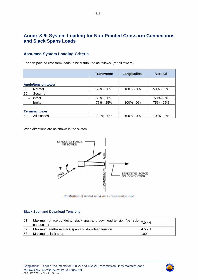
- 8-34 -
Bangladesh: Tender Documents for 230 kV and 132 kV Transmission Lines, Western Zone
Contract No. PGCB/KfW/2012.66.436/WZTLBGD 1800 WZTL vol 2 2016 11 16.docx
Annex 8-6: System Loading for Non-Pointed Crossarm Connectionsand Slack Spans Loads
Assumed System Loading Criteria
For non-pointed crossarm loads to be distributed as follows: (for all towers)
Transverse Longitudinal Vertical
Angle/tension tower
58. Normal 50% - 50% 100% - 0% 50% - 50%
59. Security
– intact 50% - 50% 50%-50%
– broken 75% - 25% 100% - 0% 75% - 25%
Terminal tower
60. All classes 100% - 0% 100% - 0% 100% - 0%
Wind directions are as shown in the sketch:
Slack Span and Downlead Tensions
61. Maximum phase conductor slack span and downlead tension (per sub-
conductor)7.0 kN
62. Maximum earthwire slack span and downlead tension 4.5 kN
63. Maximum slack span 100m

- 8-35 -
Bangladesh: Tender Documents for 230 kV and 132 kV Transmission Lines, Western Zone
Contract No. PGCB/KfW/2012.66.436/WZTLBGD 1800 WZTL vol 2 2016 11 16.docx
Annex 8-7: Minimum Thickness & Diameter of Material
The minimum thickness and diameter of material used in members and bolts shall be as detailed be-
low:
(a) For leg members and compression chords in gantries and cross
arms.
(mm) 6
(b) For other members (including earthwire peaks) carrying calculated
stress.
(mm) 5
(c) For secondary members without calculated stress. (mm) 4
(d) Gusset plates for lattice towers. (mm) 6
(e) Bolt diameter for members carrying calculated stress. (mm) 16, 24 & 32
(f) Minimum bolt diameter for secondary members without calculated
stress
(mm) 16
Annex 8-8: Electrical Clearances - Live Metal & Earthed Steelwork,Spatial Distances and Downlead Clearances
1. Electrical Clearances - Live Metal & Earthed Steelwork
Please also refer to the Bid Drawings, Section 22, Volume 2 of 3 of the bidding documents.
Description Unit 230 kV 132 kV
(a) Minimum clearance between live metal and earthed steel work
for suspension sets, and/or conductor, and/or weighted jumper
loops and/or pilot suspension sets deflected between 0o and
10o from the vertical with the conductor leaving the suspension
clamp at any angle between 0° and +10° (downwards) and/or for
tension insulators inclined between -5° and +10°.
(Swing under nil wind)
(mm) 2300 1450
(b) Minimum clearance between live metal and earthed steelwork
for suspension sets, and/or conductor, and/or weighted jumper
loops and/or pilot suspension sets deflected between 10o and
45o (10o and 15o for weighted jumper loops & pilot suspension
sets) from the vertical, with the conductor leaving the suspension
clamp at any angle between 0° and +10° and/or tension insula-
tors inclined between -5° and +10°.
(Lightning Impulse Clearance)
(mm) 1630 900
(c) Minimum clearance between live metal and earthed steelwork
for unweighted jumper loops deflected between 10° and 25°
from the vertical
(Lightning impulse clearance)
(mm) 1630 900

- 8-36 -
Bangladesh: Tender Documents for 230 kV and 132 kV Transmission Lines, Western Zone
Contract No. PGCB/KfW/2012.66.436/WZTLBGD 1800 WZTL vol 2 2016 11 16.docx
Description Unit 230 kV 132 kV
(d) Minimum clearance between live metal and earthed steelwork
for suspension sets, and/or conductor, and/or weighted jumper
loops and/or pilot suspension sets deflected between 45o and
70o from the vertical, with the conductor leaving the suspension
clamp at any angle between 0° and +10°.
(Power frequency clearance)
(mm) 900 500
Note: The actual maximum angle deflection of suspension sets, and/or conductor, and/or weighted
jumper loops and/or pilot suspension sets shall be calculated with the wind load considered for
10 minute mean wind velocity for a return period of 3 years, in accordance to EN 50341-1:2012,
paragraph 5.6.3.1.
2. Spatial Distances
230 kV 132 kV
(a) Minimum height of phase conductors at the support on
standard height, from ground level
(m) 19.9 15.5
(b) Minimum shielding angle of the earthwire (still air) from the
vertical
(degrees) 0° 30°
(c) Maximum swing of the earthwire from vertical (degrees) 85° 85°
(d) Minimum vertical spacing between adjacent phases (m) 6.0 4.0
(e) Minimum projected horizontally spacing between adjacent
phases spaced vertically
(m) - -
(f) Minimum vertical spacing between phase conductor and
earthwire
(m) 5.1 3.2
(g) Minimum horizontal spacing between adjacent phase con-
ductors spaced horizontally.
(m) - -
3. Download Clearances
230 kV 132 kV
(a)
The minimum clearance in still air at the assumed maximum
conductor temperature between adjacent downleads shall
not be less than.
(m) 4.2 2.7
(b)
In exceptional circumstances and with the approval of the
Employer, based on the condition of maximum (opposing)
conductor swing and sag, the clearance may be reduced to.
(m) - -
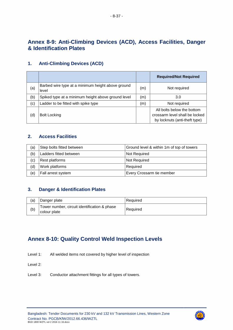
- 8-37 -
Bangladesh: Tender Documents for 230 kV and 132 kV Transmission Lines, Western Zone
Contract No. PGCB/KfW/2012.66.436/WZTLBGD 1800 WZTL vol 2 2016 11 16.docx
Annex 8-9: Anti-Climbing Devices (ACD), Access Facilities, Danger& Identification Plates
1. Anti-Climbing Devices (ACD)
Required/Not Required
(a)Barbed wire type at a minimum height above ground
level(m) Not required
(b) Spiked type at a minimum height above ground level (m) 3.0
(c) Ladder to be fitted with spike type (m) Not required
(d) Bolt Locking
All bolts below the bottom
crossarm level shall be locked
by locknuts (anti-theft type)
2. Access Facilities
(a) Step bolts fitted between Ground level & within 1m of top of towers
(b) Ladders fitted between Not Required
(c) Rest platforms Not Required
(d) Work platforms Required
(e) Fall arrest system Every Crossarm tie member
3. Danger & Identification Plates
(a) Danger plate Required
(b)Tower number, circuit identification & phase
colour plateRequired
Annex 8-10: Quality Control Weld Inspection Levels
Level 1: All welded items not covered by higher level of inspection
Level 2:
Level 3: Conductor attachment fittings for all types of towers.

- 8-38 -
Bangladesh: Tender Documents for 230 kV and 132 kV Transmission Lines, Western Zone
Contract No. PGCB/KfW/2012.66.436/WZTLBGD 1800 WZTL vol 2 2016 11 16.docx
Annex 8-11: Tower Test Requirements
Type Tests
The following towers shall require type tests to be performed before starting the manufacturing of
towers.
2DL + 9 m
2D3 + 9 m
2D25 + 9 m
2D60 + 9 m
1DL + 9 m
1D3 + 9 m
1D25 + 9 m
1D60 + 9 m
1DT60 + 9 m
The suspension towers 1DL / 2DL shall be tested up to destruction.
The angle tension towers 1D60 / 2D60 shall be tested up to ultimate loads.
All costs related to such tests shall deem to be quoted in the Contract Price - Schedule No. 4 Installa-
tion and other services.
Proto Assembly
All towers with all extensions shall require proto assembly tests to be performed in the manufacturer's
premises before starting the batch manufacturing of towers.
The shop drawings are required to be submitted in hardcopy and soft copy (AutoCAD) before proto
assembly test. This is a Hold Point. After the successful proto assembly test, the shop drawings shall
deem to be approved. The Contractor shall, then, provide the Employer complete sets of final soft
copy (Auto CAD) and hardcopies of the drawings for reference purpose. The overall responsibility of
fabricating tower members correctly lies with the Contractor only and the Contractor shall ensure that
all the tower members can be assembled/ fitted while erecting without any undue strain on them.
All costs related to such tests shall deem to be included in the Tower Supply Prices.
Visual Check, Galvanizing Test and Mechanical Test of Members/Nuts & Bolts /Plates
Before mass (batch) fabrication/manufacturing of tower materials the Contractor shall submit the proto
assembly test report of towers for acceptance of the Employer. The Contractor shall proceed mass
fabrication of towers after acceptance of the said test report by the Employer. After mass fabrication,
tower members shall visually check for dimension and galvanizing thickness (which shall include
weight basis test also). Mechanical tests shall also be done on the finished tower materials.

- 8-39 -
Bangladesh: Tender Documents for 230 kV and 132 kV Transmission Lines, Western Zone
Contract No. PGCB/KfW/2012.66.436/WZTLBGD 1800 WZTL vol 2 2016 11 16.docx
All costs related to such tests shall be deemed included in the contract price.

- 8-40 -
Bangladesh: Tender Documents for 230 kV and 132 kV Transmission Lines, Western Zone
Contract No. PGCB/KfW/2012.66.436/WZTLBGD 1800 WZTL vol 2 2016 11 16.docx
Annex 8-12: Engineering Documents to be Submitted by Contractor
Clause Reference Document Description Comment
8.2.21 Design calculation
8.2.22 Fabrication drawings
8.6.1 Method statement - tower erection
8.7.1 Material test certificates
8.7.1 Bolt & nut test certificates
8.7.2 Welding procedures
8.7.2 Welder's test certificates
8.7.2 NDT procedures
8.7.2 NDT inspection reports
8.7.5 Galvanising test records if requested
8.7.5 Ingot zinc certificates
8.7.5 Pot melt analysis
8.7.7 Prototype tower test programme
8.7.7 Prototype test reports
8.7.8 Certificate of conformity
8.7.9 Tower erection records
Annex 8-13: Notification and Hold Points
Clause Reference Notification Points Hold Points
8.2.21 Design calculation
8.2.22 Fabrication drawings
8.4.3 Misplaces holes
8.4.4 Formation of bends
8.4.6 Erection marks
8.6.1 Method statement
8.6.5 Damaged galvanizing
8.7.2 Welding inspection/testing Welding procedure
8.7.2 NDT organisation
8.7.2 NDT procedure
8.7.4 Prototype tower erection
8.7.7 Prototype tower test Prototype tower test programme

- 8-41 -
Bangladesh: Tender Documents for 230 kV and 132 kV Transmission Lines, Western Zone
Contract No. PGCB/KfW/2012.66.436/WZTLBGD 1800 WZTL vol 2 2016 11 16.docx
Annex 8-14: Reference Standards
The reference standards and other documents referred to in this specification are listed below:
IEC 60652: Loading Tests on Overhead Line Towers
BS 4: Structural Steel Sections, Part 1: Specification for hot rolled sections
BS 183: Specification for general purpose galvanized steel wire strand
BS EN 10244-2: Specification for testing zinc coatings on steel wire and for quality require-
ments.
BS EN 134411-1: Specification for thimbles for wire ropes.
BS EN ISO 1461: Specification for hot-dipped galvanizing coating, on iron and steel article.
BS 970: Specification for wrought steel for mechanical and allied engineering pur-
poses. General inspection and testing procedures and specific requirements
for carbon, carbon manganese, alloy and stainless steel
BS EN 10083, 4, 5, 7, 8;
BS EN 10095,
BS EN 10250-4;
BS PD 970; BS EN 515:
Specification for wrought aluminium and aluminium alloys for general engi-
neering purposes bars, extruded round tubes and sections.
BS EN 573-3, 4;
BS EN 755-1 to 9;
BS EN 12020-1,2;
BS 1574:
Specification for split cotter pins.
BS EN 1563: Specification for spheroidal graphite or nodular graphite cast iron.
BS 3643: ISO Metric screw threads. Part 2: Specification for selected limits of size
BS EN 1714: Method of ultrasonic examination of welds.
Method of manual examination of fusion welds in ferric steel.
BS 4102: Steel wire and wire products for fences.
BS 4190: Specification for ISO metric hexagon bolts, screws and nuts.
BS 4211: Ladders for permanent access to chimneys, other high structures, silos and
bins.
BS 4320: Specification for metal washer for general engineering purposes. Metric se-
ries.
BS 4464: Specification for spring, washers for general engineering and automobile.
BS 4592: Industrial type metal flooring, walkways and stair treads. BS EN ISO 14122-
1 to 3
BS EN 10210-2: Hot rolled structural steel sections. Specification for hot-finished hollow sec-
tions.
BS EN 10056-1: Equal and unequal angles.
BS EN 1011-1,2: Specification for arc welding of carbon and carbon manganese steels
BS EN 970: Code of practice. Visual inspection of fusion welded joints.

- 8-42 -
Bangladesh: Tender Documents for 230 kV and 132 kV Transmission Lines, Western Zone
Contract No. PGCB/KfW/2012.66.436/WZTLBGD 1800 WZTL vol 2 2016 11 16.docx
BS 5531: Code of practice. For safety in erecting structural frames.
BS 5950: Structural use of steelwork in buildings.
BS ISO 10160: Methods of ultrasonic testing and specifying, quality grades of ferric steel
plates.
BS EN ISO 9934: Methods for magnetic particle flow detection.
BS EN 1562: Specification for malleable cast iron.
BS EN 287: Approval testing of welders for fusion welding.
BS EN ISO 15607: Specification and approval of welding procedures for metallic materials.
BS EN ISO 15609;
BS EN ISO 15610,
15611, 15612, 15613,
1561; BS EN 353:
Personal protective equipment against falls from heights
BS EN 353-1: Guided type fall arresters including a rigid anchorage line.
BS EN 353-2: Guided type fall arresters including a flexible anchorage line.
BS EN 360: Personal protective equipment against falls from a height. Retractable type
fall arrestors.
BS EN 1179: Specification for Zinc & Zinc Alloys - Primary zinc.
BS EN 10024: Hot rolled taper flange I-sections. Tolerance on shape and dimensions.
BS EN 10025: Specification for hot rolled products of non-alloyed structural steels and their
technical delivery requirements.
BS EN 10029: Tolerance on dimensions, shape and mass of hot rolled steel plate 3 mm
thick or above.
BS EN 10034: Structural steel I and H sections. Tolerance on shape and dimensions.
BS EN 10056: Specification for structural steel equal and unequal angles; Part 2: Toler-
ance on shape and dimension
BS EN 10163: Delivery requirements for surface conditions of hot rolled steel plates, wide
flats and sections.
Part 1: General requirements;
Part 2: Plates and wide flats;
Part 3: Sections
BS EN 10210-1: Hot finished structural hollow sections of non-alloy and fine grained struc-
tural steels - Technical delivery requirements
BS 8100-3 Code of Practice for strength assessment of members of lattice towers
masts.
ANSI/ASCE Std 10-15 Design of Steel Transmission Towers.
BS EN 50341-1:2012: Overhead electric lines exceeding AC 1 kV - Part 1: General requirements -
Common specifications
ASCE Manual and reports on Engineering Practice no. 74. Guideline for Electrical Transmission Line,
Structural Loading Third Edition.

- 9-1 -
Bangladesh: Tender Documents for 230 kV and 132 kV Transmission Lines, Western Zone
Contract No. PGCB/KfW/2012.66.436/WZTLBGD 1800 WZTL vol 2 2016 11 16.docx
9. Insulators
9.1 Scope
Both, the type of insulator unit and insulator set, whether suspension or tension used on each type of
support, shall be approved, and shall have proven use under similar environmental and operational
conditions.
Insulator strings shall comprise of porcelain disc insulator units. All types of insulators to be supplied
under this Contract shall be supplied from the same manufacturer.
Please refer to Annex 9-1 for details of the specific requirements. Where specified porcelain insulators
shall be glazed Munsell Grey in accordance with BS 5252 or equivalent.
9.2 Design
9.2.1 General
All insulator units shall be designed to withstand the design service voltages including lightning,
switching and power frequency, the mechanical loads relevant to the installation - service - mainte-
nance conditions, the service temperature and environmental effects. Internal stresses due to expan-
sion and contraction of any part of the insulator unit shall not lead to deterioration.
The design of insulator units shall be such as to avoid local corona formation and no significant radio
interferences shall be exhibited. Cap & pin insulator units shall comply with the general requirements
of the IEC 60305 standard, except where specified otherwise in this Specification and insulator units
shall have straight head design to avoid concentration of mechanical stress. Cross section sketch of
insulators unit showing the head design is included in the enclosed drawing in Section 19.
9.2.2 Electrical and Mechanical Characteristics
The individual insulator units shall be complete insulator sets shall have the electrical and mechanical
characteristics stated in Annex 9-2.
9.2.3 Couplings
Couplings between individual insulator units shall be as specified in Annex 9-1. Ball and socket
couplings shall be in accordance with the requirements of IEC 60120. Sockets shall either have W
type security clips, or a split pin (R) clip in accordance with the requirements of IEC 60372 as speci-
fied.

- 9-2 -
Bangladesh: Tender Documents for 230 kV and 132 kV Transmission Lines, Western Zone
Contract No. PGCB/KfW/2012.66.436/WZTLBGD 1800 WZTL vol 2 2016 11 16.docx
9.2.4 Pollution
The design of insulator units shall take into account the principles contained in IEC 60815 for the
specified pollution category. However, minimum creepage values (mm/kV) shall be as specified.
9.2.5 Zinc Sleeve
Cap and pin insulator units shall where specified be fitted with zinc sleeve pins to prevent cracking due
to pin corrosion caused by the effects of pollution and high humidity. The exposed part of the sleeve
shall have a mass of at least 5 (five) gram and metallurgic alloy bonded to the insulator pin.
9.2.6 Insulator Protective Device
The design of insulator protective fittings including corona shields shall comply with the following re-
quirements:
a) Shall effectively protect the insulator units, and the fittings from damage caused by power arcs;
b) shall effectively improve the voltage distribution along the insulator string;
c) shall effectively improve the corona performance of the insulator set;
d) shall be designed in such a way as not to be subject to breakage fatigue due to wind induced
vibration;
e) shall withstand a specified mechanical load.
f) shall be suitable where specified for live-line maintenance.
For details of the materials, workmanship and quality control requirements for insulator protective fit-
tings reference shall be made to Section 10 of this specification.
9.2.7 Low Duty Insulator Sets
Low duty tension sets shall be used for the downleads between terminal supports and substation gan-
try structures or other positions where the conductor tensions are of a reduced value. At the lower
end of the downleads the low duty tension sets shall be capable of having their units reversed.
9.2.8 Tension Insulator Sets-Earth End Linkages
Additional earth end adjustable linkages shall be provided where necessary to ensure that either the
specified clearance is maintained between the tension insulator set and the support body/crossarm, or
that satisfactory pairing is achieved between the phase sub-conductors.
9.3 Materials
9.3.1.1. High grade, wet process porcelain used in the manufacturer of insulator units shall comply
with the requirement of IEC 60672.

- 9-3 -
Bangladesh: Tender Documents for 230 kV and 132 kV Transmission Lines, Western Zone
Contract No. PGCB/KfW/2012.66.436/WZTLBGD 1800 WZTL vol 2 2016 11 16.docx
9.3.1.2. Insulator caps and bases of malleable cast iron shall be manufactured from a suitable grade
of MCI complying with the requirement of BS EN 1563 for spheroidal graphite, or BS EN 1562 for
white heart and pearlytic. Ductile cast iron of suitable grade may be used for caps and bases.
9.3.1.3. Insulator end fittings of forced or cast aluminium alloy shall be manufactured from a suitable
grade of aluminium alloy complying with the requirements of BS EN 515, 573, 586, 603, 604 or BS EN
1559, 1676, 1706 and/or BS EN 1676 or equivalent respectively.
9.3.1.4. Security 'W' clips shall be of phosphor-bronze composition in accordance with the require-
ments of BS EN 1172, 1652, 1653, 1654 or equivalent and supplied in the half-hard condition with a
minimum harness of 155 VPN.
9.3.1.5. Security 'R' clips shall be of austenitic stainless steel capable of complying with the require-
ments of relating to inter-crystalline corrosion tests of BS 970: Part 1 and BS EN 10084, 10085,
10087, 10095, 10250 and PD 970.
9.3.1.6. Zinc sleeve shall have a total impurity not greater than 0.2 percent and shall comply with the
requirement of BS EN 1179 or equivalent.
9.4 Workmanship
9.4.1 Insulator Units
9.4.1.1. The dimensions of all insulator units, together with materials and grades and other perti-
nent information shall be shown on the contract drawings. Contract drawings shall be submitted to the
Engineer. This is a Hold Point.
9.4.1.2. Particular regard shall be paid to those dimensions which involve interchangeability, cor-
rect assembly and those for which gauges are specified. Where appropriate insulator caps and pins
shall comply with the requirement of IEC 60120, IEC 60372 and IEC 60471.
9.4.1.3. Porcelain shall be sound, thoroughly vitrified and free from defects and blemishes
which might adversely affect the life of the insulator units.
9.4.1.4. Cement used in the construction of an insulator unit shall not fracture by virtue of expan-
sion, nor loosen by contraction and proper care shall be taken to locate the individual parts correctly
during assembly. The cement shall not give rise to chemical reaction with metal fittings nor the zinc
collars. The cement thickness shall be as uniform as possible.
9.4.1.5. All insulator caps and bases are to be free from flaws, blowholes and shall be of a close-
grained quality.
9.4.1.6. Insulator pins shall be round, free from cracks, surface flaws, lamination and other de-
fects.
9.4.1.7. The zinc sleeve shall not be porous and all mould lines shall be removed. The cement
level shall be approximately at the mid-point of the sleeve.
- 9-4 -
Bangladesh: Tender Documents for 230 kV and 132 kV Transmission Lines, Western Zone
Contract No. PGCB/KfW/2012.66.436/WZTLBGD 1800 WZTL vol 2 2016 11 16.docx
9.4.2 Identification and Marking
All insulator units shall be marked to ensure a system of traceability. Each unit shall be clearly and in-
delibly marked as follows on the insulating component according to the requirements of
IEC 60383-1:
a) Electromechanical failing load;
b) Name or trade mark of the manufacturer;
c) Year of manufacture.
9.4.3 Installation Criteria
The manufacturer shall where necessary provide comprehensive instructions in a suitable format re-
garding, the handling and installation of insulator units.
9.4.4 Erection
9.4.4.1. The Contractor shall provide the Engineer with a method statement giving sequential de-
tails of the proposed erection method. The method statement shall be submitted to the Employer, the
requisite period before insulator set erection commences. This is a Hold Point.
9.4.4.2. Care shall be exercised in the handling and erection of insulator units to prevent scratch-
es, chipping or cracking of the insulation medium.
9.4.4.3. The Engineer shall be reasonable entitled to request the removal and destruction of any
insulator units from a string which they notice has been severely handled or knocked during erection.
All units which are scratched, chipped or abraded shall be removed and replaced. Insulator units and
fittings shall be laid on plastic sheets prior to erection and any foreign matter shall be removed prior to
installation.
9.4.4.4. The Contractor shall ensure that insulator units are not strained or damaged in any
way during, erection.
9.4.4.5. All bolt threads shall be coated with an approved grease immediately before erection.
9.5 Protective Treatment
9.5.1 All insulator caps, bases and pins shall either be inherently resistant to atmospheric corrosion
or suitably protected against corrosion, such as may occur in transit, storage and in service. All ferrous
parts which will be exposed to the atmosphere in service, except those made in the appropriate
grade of stainless steel, shall be protected by hot dipped galvanizing to comply with the requirements
of BS ISO 1461. All manufacturing processes shall be completed prior to galvanizing.
9.5.2 The ingot zinc used for galvanizing shall comply with the requirements of BS EN 1179 or equiv-
alent.
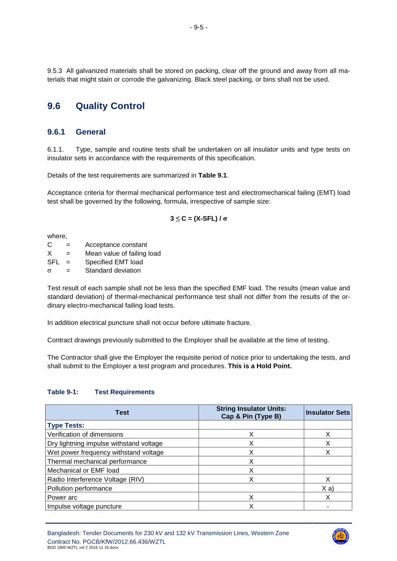
- 9-5 -
Bangladesh: Tender Documents for 230 kV and 132 kV Transmission Lines, Western Zone
Contract No. PGCB/KfW/2012.66.436/WZTLBGD 1800 WZTL vol 2 2016 11 16.docx
9.5.3 All galvanized materials shall be stored on packing, clear off the ground and away from all ma-
terials that might stain or corrode the galvanizing. Black steel packing, or bins shall not be used.
9.6 Quality Control
9.6.1 General
6.1.1. Type, sample and routine tests shall be undertaken on all insulator units and type tests on
insulator sets in accordance with the requirements of this specification.
Details of the test requirements are summarized in Table 9.1.
Acceptance criteria for thermal mechanical performance test and electromechanical failing (EMT) load
test shall be governed by the following, formula, irrespective of sample size:
3 ≤ C = (X-SFL) / σ
where,
C = Acceptance constant
X = Mean value of failing load
SFL = Specified EMT load
σ = Standard deviation
Test result of each sample shall not be less than the specified EMF load. The results (mean value and
standard deviation) of thermal-mechanical performance test shall not differ from the results of the or-
dinary electro-mechanical failing load tests.
In addition electrical puncture shall not occur before ultimate fracture.
Contract drawings previously submitted to the Employer shall be available at the time of testing.
The Contractor shall give the Employer the requisite period of notice prior to undertaking the tests, and
shall submit to the Employer a test program and procedures. This is a Hold Point.
Table 9-1: Test Requirements
TestString Insulator Units:
Cap & Pin (Type B)Insulator Sets
Type Tests:
Verification of dimensions X X
Dry lightning impulse withstand voltage X X
Wet power frequency withstand voltage X X
Thermal mechanical performance X
Mechanical or EMF load X
Radio Interference Voltage (RIV) X X
Pollution performance X a)
Power arc X X
Impulse voltage puncture X -

- 9-6 -
Bangladesh: Tender Documents for 230 kV and 132 kV Transmission Lines, Western Zone
Contract No. PGCB/KfW/2012.66.436/WZTLBGD 1800 WZTL vol 2 2016 11 16.docx
TestString Insulator Units:
Cap & Pin (Type B)Insulator Sets
Zinc sleeve X -
Residual strength X -
Sample Tests:
Verification of dimensions X -
Verification of locking system and displacement X -
Temperature cycle test X -
Mechanical or EMF load X -
Porosity X -
Galvanizing X -
RIV X -
Impulse Voltage puncture X -
Zinc sleeve test X -
Head design test X
Routine Tests:
Visual inspection X
Mechanical X
Electrical X
a) Um ≤ 245 kV;
9.6.2 Type Tests
(i) String Insulator Units
Type test for string (cap and pin), insulator units shall be in accordance with all the requirements of
IEC 60383-1. Methods of tests shall comply with the requirements of the above standard, unless oth-
erwise specified in the following clauses.
(ii) Insulator Sets
Type tests for insulator sets comprising cap and pin, insulator units complete with all appropriate fit-
tings including insulator protective fittings shall be undertaken in accordance with the requirements
of IEC 60383-2, to determine the dry lightning impulse withstand voltage, wet switching impulse with-
stand voltage and the power frequency withstand voltage as appropriate.
If Type test for insulator sets are not available, these shall be provided during execution stage.
The manufacture shall submit details of the proposed simulation of the support structure and mounting
arrangement of the insulator sets to the Employer. This is a Hold Point.
1 Radio Interference & Corona
Radio interference type tests shall be under-taken both on single insulator units followed by a com-
plete insulator set test. All radio noise measurements shall be made at a frequency of 1.0 MHz (9 kHz
band width), using a radio interference measuring set having a response conforming to CISPR Publi-
cation 1. The test circuit shall conform to IEC 60437 and shall be calibrated in-situ to determine any
circuit losses. The set shall be adjusted to indicate correctly, or alternatively an appropriate correction
(in dB) shall be added to the measurement. Ideally the measurement shall be made using a 300 ohm

- 9-7 -
Bangladesh: Tender Documents for 230 kV and 132 kV Transmission Lines, Western Zone
Contract No. PGCB/KfW/2012.66.436/WZTLBGD 1800 WZTL vol 2 2016 11 16.docx
load resistance. All readings shall be converted to dB above 1μV across 300 ohms, taking into ac-
count any corrections necessary.
The single unit test voltage shall be that which would appear across the live end unit in the complete
set test and shall be determined by an initial voltage distribution measurement.
Before final readings of the radio noise are taken it is permissible to wipe the unit with a dry clean
cloth, and to condition it at not more than 50% above the test voltage for up to 2 minutes. This may be
repeated if the first measurement exceeds the first level.
The maximum permitted radio noise levels per insulator unit shall not exceed the values stated in
Annex 9-2.
The number of units tested shall be either 1.5 times the number of units in a complete string or six
units whichever is the greater. The choice of set make up to be tested shall be that likely to give the
highest voltage across the live end unit with the shortest arc gap. Three pairs of units shall be selected
from those previously tested as single units (the most noisy units).
Each pair shall comprise the live end and penultimate live end unit of a single string or the pair of live
end units for a duplex string, each pair shall be tested in turn in the set.
The radio noise test voltage and limits shall be in accordance with IEC 60437. None of the tests shall
give rise to radio noise levels exceeding the specified limits. Each set shall also be tested for visible
corona extinction. Light shall be excluded from the laboratory and the observer's eyesight allowed time
to become accustomed to the dark. The voltage shall be increased until corona appears on the string.
The voltage shall be gradually reduced until all discharges on the string are extinguished. The extinc-
tion voltage shall be measured, and shall be minimum 0.8 times the nominal system voltage plus 5%.
All appropriate action shall be taken to eliminate discharges from test equipment, thereby avoiding
spurious corona observations and radio inference readings.
2 Type Tests - Pollution
Artificial pollution tests (salt fog method) in accordance with the requirements of IEC 60507 shall be
undertaken.
The salinity of the salt solution and the power frequency withstand voltage shall be in accordance
with Annex 9-3.
3 Power Arc Tests
a. Power Arc Test for complete Insulator Set.
64. Power arc tests to simulate the effect of short circuit current shall be undertaken on the com-
plete insulator set.
65. The power arc current shall be in accordance with Annex 9-2.
66. The function of the insulator protective devices shall not be greatly affected by the power arc.
b. Power Arc Test for Insulator Unit.
67. Power arc test shall also be performed to prove the ability of the insulator units to withstand the
heat generated by power arc. This test shall be performed in the following manner:
68. Nine (9) insulator units of each type shall be chosen for the power arc test. Tests shall be con-
ducted on the above chosen insulator units in three (3) strings of three (3) insulator units each.

- 9-8 -
Bangladesh: Tender Documents for 230 kV and 132 kV Transmission Lines, Western Zone
Contract No. PGCB/KfW/2012.66.436/WZTLBGD 1800 WZTL vol 2 2016 11 16.docx
Strings shall be mounted vertically without arcing horns or conductors. The current and duration
of power arc shall be 12kA (symmetrical r.m.s) and 0.1s or 6kA (symmetrical r.m.s) and 0.2 s.
69. No shed breakage shall occur during the power arc test. Peeling-off or bum out of glaze on the
insulator surface and partial rib chip shall be permitted. If two or more insulator units string
break in the power arc test, this insulator design is considered to have failed to meet the specifi-
cations. In case one insulator unit fails in the test, re-test on another nine (9) insulator units shall
be conducted in the same manner. Failure of anyone unit in the re-test means that the insulator
design has failed to meet the specification.
4 Impulse Voltage Puncture Tests
Impulse voltage puncture tests shall be undertaken in accordance with the requirements of IEC 61211.
5 Residual Strength Tests
Residual strength tests shall be undertaken in accordance with the recommendations of IEC 60797.
With all the outer shed material removed, the insulator stubs shall be capable of withstanding 80% of
the rated minimum failing load for 1 minute.
The test shall be continued to destruction (where it is practicable) to obtain a representative value of
the actual falling load, and allow the modes of failure to be determined.
9.6.3 Sample Tests
9.6.3.1. The Contractor shall, give the Employer the requisite period of notice prior to undertaking
Sample Tests. This is a Notification Point.
9.6.3.2. Sample tests for string insulator (cap & pin) insulator units shall be undertaken in accord-
ance with the requirements of IEC 60383-1, see also Table 9-1.
9.6.3.3. Sample tests in respect of radio noise shall be undertaken on single units only in accord-
ance with the requirement of Clause 9.6.2 (iii) of this specification. The sample size shall generally be
0.5% of the batch offered for acceptance.
9.6.3.4. The number of sample to be checked regarding the metallurgical bond of the zinc sleeve
to the pin shall be in accordance with IEC 61325.
9.6.3.5. The metallurgical purity of the zinc shall be established by chemical analysis to ensure
that any impurities do not sensitize the zinc to intergranular corrosion.
9.6.3.6. The zinc sleeve of each sample tested for mechanical strength shall also be inspected
according to IEC 61325, to ensure no radial and circumferential cracking has occurred.
9.6.3.7. Three insulators shall be selected at random from each lot of the order and their straight
head design checked against the straight head design of the manufacturer's cross-section drawing.

- 9-9 -
Bangladesh: Tender Documents for 230 kV and 132 kV Transmission Lines, Western Zone
Contract No. PGCB/KfW/2012.66.436/WZTLBGD 1800 WZTL vol 2 2016 11 16.docx
9.6.4 Routine Tests
Routine tests for string insulator (cap and pin) insulator units shall be undertaken in accordance
with the requirements of IEC 60383-1, see also Table 9-1.
9.6.5 Galvanizing
Tests for galvanized insulator caps, bases and pins shall be carried out at the works to ensure compli-
ance with the requirements of ISO 1461. Details of the test results shall be made available to the Em-
ployer upon request.
Certificates relating to the ingot zinc used for galvanizing shall also be made available to the Em-
ployer upon request.
9.6.6 Test Certificates
9.6.6.1 All metallic materials used in the manufacture of insulator caps, bases and pins shall be
covered by test certificates stating their mechanical, chemical and where specified the impact proper-
ties and clearly showing the cast numbers to prove compliance with the requirements of this specifica-
tion and BS EN 1563, BS EN 1562, BS 970 and BS EN 10084, BS EN 10085 etc., BS EN 515, 573,
586, 603, 606, BS EN 1559, 1676, 1707, BS EN 1172, 1652, 1653, 1654, BS EN 1179 as appropriate.
9.6.6.2 Test certificates for metallic materials and bolts shall be made available to the Employer
upon request.
9.6.6.3 Test certificates covering type and sample tests shall be made available to the Employer
upon request.
9.6.7 Certificate of Conformity
When requested copies of the following certificates/records shall also be forwarded:
a) Routine test records
b) Metallic material test certificates
c) Galvanizing test records
d) Ingot zinc certificates
e) Metallurgical purity test records for zinc sleeve.
9.6.8 Installation
The Contractor shall be responsible for checking that all insulator sets are complete and that all bolts,
split pins and security clips have been correctly installed. A record of this work shall be kept by the
Contractor and made available to the Employer upon request.

- 9-10 -
Bangladesh: Tender Documents for 230 kV and 132 kV Transmission Lines, Western Zone
Contract No. PGCB/KfW/2012.66.436/WZTLBGD 1800 WZTL vol 2 2016 11 16.docx
Annex 9-1: Insulator Types and Uses
1. 230 kV Lines
Insulator Set Type
Suspension /
Heavy Suspension* Tension
Low Duty
Tension
Jumper
Suspen-
sion
Nominal system voltage 230 kV
String configuration single twin single single
Reference drawing
Insulator unit type Cap & pin type disc insulator
Coupling type as per IEC 60305 Ball & socket
Insulating material Porcelain
Security clip type R
Zinc sleeve Required
Head design Straight head
* for 2D10 tower
2. 132 kV Lines
Insulator Set Type
Suspension /
Heavy Suspension* Tension
Low Duty
Tension
Jumper
Suspen-
sion
Nominal system voltage 132 kV
String configuration single single single single
Reference drawing
Insulator unit type Cap & pin type disc insulator
Coupling type as per IEC 60305 Ball & socket
Insulating material Porcelain
Security clip type R
Zinc sleeve Required
Head design Straight head
* for 1D10 tower

- 9-11 -
Bangladesh: Tender Documents for 230 kV and 132 kV Transmission Lines, Western Zone
Contract No. PGCB/KfW/2012.66.436/WZTLBGD 1800 WZTL vol 2 2016 11 16.docx
Annex 9-2: Electrical & Mechanical Characteristics
1. 230 kV Lines
Parameter
Insulator Set Type
Suspension/
Jumper
Suspension
Heavy
Suspension
Tension
(Twin)
Upright
Low
Duty
Inverted
Low
Duty
Pollution category Medium II
Nominal creepage mm 4900
Insulator type Cap & pin type disc insulators
Insulator unit reference U120B U210B U210B U120B U120B
Glaze colour Grey Brown Brown Grey Grey
Unit puncture voltage kV 110 125 125 110 110
Number of insulator units per
string
17 14 2 x 14 17 17
Dielectric material Porcelain
Max. insulator string length
without fittings
mm 17x146 14x170 14x170 17x146 17x146
Dry lightning impulse withstand
voltage
kV 1050
Wet power frequency with-
stand voltage
kV 460
Power arc for insulator set
70. Current kA 31,5
71. Duration s 0.5
Power arc for string insulator
units: Current for duration
kA for s 12 for 0.1 or 6 for 0.2
Arc gap nominal mm 2100 2100 2100 1910 1910
RIV level per unit δB 50
RIV level per set δB 36
Mechanical/ electromechanical
failing load
kN 120 210 2 x 210 120 120
2. 132 kV lines
Parameter
Insulator Set Type
Suspension/
Jumper
Suspension
Heavy
Suspension
Tension
(Single)
Upright
Low
Duty
Inverted
Low
Duty
Pollution category Medium II
Nominal creepage mm 2900
Insulator type Cap & pin type disc insulators
Insulator unit reference U70BL U120B U120B U70BL U70BL
Glaze colour Brown Grey Grey Brown Brown
Unit puncture voltage kV 110 110 110 110 110
Number of insulator units per
string
10 10 11 11 11
Dielectric material Porcelain

- 9-12 -
Bangladesh: Tender Documents for 230 kV and 132 kV Transmission Lines, Western Zone
Contract No. PGCB/KfW/2012.66.436/WZTLBGD 1800 WZTL vol 2 2016 11 16.docx
Parameter
Insulator Set Type
Suspension/
Jumper
Suspension
Heavy
Suspension
Tension
(Single)
Upright
Low
Duty
Inverted
Low
Duty
Max. insulator string length
without fittings
mm 10x146 10x146 10x170 11x146 11x146
Dry lightning impulse withstand
voltage
kV 650
Wet power frequency with-
stand voltage
kV 275
Power arc for insulator set
72. Current kA 31,5
73. Duration s 0.5
Power arc for string insulator
units: Current for duration
kA for s 12 for 0.1 or 6 for 0.2
Arc gap nominal mm 1120 1120 1120 1000 1000
RIV level per unit δB 42
RIV level per set δB 30
Mechanical/ electromechanical
Failing load
kN 70 120 210 70 70
Annex 9-3: Type Test - Pollution IEC 60507
Salt solution salinity Not required
Annex 9-4: Engineering Documents to be Submitted by Contractor
Clause Reference Document Description Comment
9.4.1 Insulator units - contract drawings
9.4.3 Installation procedures Where necessary
9.4.4 Erection - method statement
9.6.1 Insulator units - type test certificates If tests waived
9.6.1 Insulator sets - type test certificates If tests waived
9.6.1 Type test - programme & procedure
9.6.1 Details of support simulations
9.6.5 Galvanising, test results If requested
9.6.5 Ingot zinc certificates If requested
9.6.6 Material test certificates If requested
9.6.6 Insulator units - type test results
9.6.6 Insulator units - sample test results
9.6.6 Insulator units - routine test results If requested
9.6.7 Certificates of conformity
9.6.8 Installation records If requested

- 9-13 -
Bangladesh: Tender Documents for 230 kV and 132 kV Transmission Lines, Western Zone
Contract No. PGCB/KfW/2012.66.436/WZTLBGD 1800 WZTL vol 2 2016 11 16.docx
Annex 9-5: Notification and Hold Points
Clause Reference Notification Point Hold Point
9.4.1 Contract drawings
9.4.4 Method statement
9.6.1 Insulators - type tests
9.4.4 Type tests - support simulation details
9.6.8 Insulator - sample tests
Annex 9-6: Reference Standards
The reference standards and other documents referred to in this section of the specifications are listed
below:
IEC 60120: Dimensions of ball and socket couplings of string, insulator units
IEC 60305: Characteristics of string, insulator units of cap and pin type
IEC 60372: Locking devices for ball and socket coupling of string insulator units -
Dimensions and tests
IEC 60383: Insulators for overhead lines with a nominal voltage above 1000V
Part 1: Ceramic or glass insulator units for ac systems - Definitions, test
methods and acceptance criteria
Part 2: Insulator string and insulator sets for ac - Definitions, test method and
acceptance criteria
IEC 60437: Radio interference tests on high voltage insulators
IEC 60471: Dimensions of clevis and tongue couplings of string insulator units
IEC 60507: Artificial pollution tests on high-voltage insulators to be used on a.c.
systems
IEC 60672: Specification for ceramic and glass insulating materials
IEC 60797: Residual strength of string, insulator units of glass or ceramic, mate-
rials for overhead lines after mechanical damage of the dielectric
IEC 60815: Guide for selection of insulators in respect of polluted conditions
IEC 61211: Insulators of ceramic material or glass for overhead lines with a nom-
inal voltage greater than 1000V - Puncture testing
IEC 61325: Insulators for overhead lines with nominal voltage > 1000 V
ISO 1461: Specification for hot-dipped galvanizing coating on iron and steel arti-
cles

- 9-14 -
Bangladesh: Tender Documents for 230 kV and 132 kV Transmission Lines, Western Zone
Contract No. PGCB/KfW/2012.66.436/WZTLBGD 1800 WZTL vol 2 2016 11 16.docx
BS EN 10084: Specification for wrought steel for mechanical and applied Engineer-
ing purposes
BS EN 10085; BS EN 10087;
BS EN 10095; BS EN 10250;
PD 970; BS EN 515:
Specification for wrought aluminium and aluminium alloy
BS EN 573; BS EN 586;
BS EN 603; BS EN 604;
BS EN 1559:
Specification for Aluminium and aluminium alloy ingots and casting
for general engineering purposes
BS EN 1676; BS EN 1706;
BS EN 1172:
Specification for Rolled Copper and Copper Alloys: Sheet, strip and
foil
BS EN 1652; BS EN 1653;
BS EN 1654; BS EN 1563
Spheroidal graphite cast iron
BS 4190: Specification for ISO metric hexagon bolts, screws and nuts
BS 5252: Framework for colour coordinations of buildings
BS EN 1562 Specification for malleable cast iron
BS EN 1179: Specification for Zinc & Zinc Alloys
BS EN 1676: Aluminium & aluminium alloys - Alloyed ingots for re-melting
CISPR: Publication 1 Specification for CISPR radio interference measuring
apparatus for the frequency range 0.15 to 30 MHz.
BS EN 50341-1:2012: Overhead electric lines exceeding AC 1 kV - Part 1: General require-
ments - Common specifications

- 10-1 -
Bangladesh: Tender Documents for 230 kV and 132 kV Transmission Lines, Western Zone
Contract No. PGCB/KfW/2012.66.436/WZTLBGD 1800 WZTL vol 2 2016 11 16.docx
10. Insulator and Conductor Fittings
10.1 Scope
10.1.1 Types and Uses
The type and arrangement of all insulator and earthwire sets inclusive of all insulator and earthwire set
fittings, suspension clamps, conductor tension fittings and insulator protective devices shall be ap-
proved. Please refer to Annex 10-1, Annex 10-2 and Annex 10-3 for details of the specific require-
ments.
10.2 Design
10.2.1 General
10.2.1.1. All insulator and conductor fittings shall be designed so as to:
a. avoid damaging the conductor under all service conditions;
b. withstand the mechanical loads relevant to the installation-service-maintenance conditions, the
design service current including short circuit effects, the service temperature and environmental
effects;
c. be free from visible and audible corona discharge and radio interference at the voltage levels
specified, except those designed exclusively for use on earthwires;
d. minimize the number of parts and the possibility of incorrect assembly and installation;
e. ensure that individual components are secured against becoming loose in service, and all
threaded fasteners shall be locked;
f. Compression fittings after compression shall not permit relative movement between the individ-
ual layers of the conductor.
g. from material, which have sufficient strength, ductility and environmental resistance to withstand
the static and dynamic loading.
10.2.1.2. Where appropriate insulator and conductor fittings shall be in accordance with the re-
quirements of IEC 61284. Ball and socket coupling shall be in accordance with the requirements of
IEC 60120. Socket fitting shall be designed for 'W' type security clips or 'R' type security pins in ac-
cordance with the requirements of IEC 60372 as appropriate, clevis tongue couplings shall be in ac-
cordance with the requirements of IEC 60471.
10.2.1.3. All factory formed helical fittings shall be performed with a right hand lay and shall com-
pletely enclose the conductor except for small gaps required to ensure that all rods make good contact
with the conductor over their entire length.
10.2.2 Live-Line Working
Where live-line working is specified in Annex 10-1 the design of the fittings shall take into account the
following requirements:

- 10-2 -
Bangladesh: Tender Documents for 230 kV and 132 kV Transmission Lines, Western Zone
Contract No. PGCB/KfW/2012.66.436/WZTLBGD 1800 WZTL vol 2 2016 11 16.docx
a. both suspension and tension insulator sets shall include either clevis fittings, or yoke plates in-
corporating cut-outs correctly dimensioned suitable for live-line working;
b. the minimum distance between the attachment point and the shoulder for clevis fittings shall not
be less than 125 mm, where no yoke plate is adjacent;
c. clevis and tongue and clevis-clevis connections shall be provided with 'R' type security pins;
d. insulator protective devices attached to yoke plates shall utilise captive bolts.
10.2.3 Sag Adjusters
All tension insulator sets shall incorporate sag adjusters for adjusting the sag of either Individual phase
conductors or sub-conductors forming a phase conductor bundle. The total range of linear adjustment
and individual steps shall be as specified in Annex 10-1.
When specified low-duty tension insulator sets shall incorporate a turnbuckle for adjusting the sag of
the complete downlead. The turnbuckle where appropriate shall comply with the requirements of BS
4429 and shall be fitted with locknuts. The total range of linear adjustment shall be as specified in An-
nex 10-1. The turnbuckle shall be fitted in the earth end of the low duty tension insulator set.
10.2.4 Insulator Protective Fittings:
10.2.4.1 The design of insulator protective fittings including corona shields shall comply with the
following requirements:
a. shall effectively protect the insulator units, and the fittings from damage caused by power arcs;
b. shall effectively improve the voltage distribution along the insulator string;
c. shall effectively improve the corona performance of the insulator set;
d. shall be designed in such a way as not to be subject to breakage fatigue due to wind induced
vibration;
e. shall withstand a specified mechanical load.
10.2.4.2 For details of the materials, workmanship and quality control requirements for insulator
protective fittings reference shall be made to clauses 10.3, 10.4 & 10.6 of this Section 10.
10.2.4.3 The end of all arcing horns shall be formed into smooth hemispheres. The end of tubular
arcing horns shall also be sealed.
10.2.5 Electrical and Mechanical Characteristics
The insulator and earthwire set fittings, suspension clamps, conductor tension fittings and insulator
protection devices shall have the electrical and mechanical characteristics specified in Annex 10-1,
Annex 10-2 and Annex 10-3.

- 10-3 -
Bangladesh: Tender Documents for 230 kV and 132 kV Transmission Lines, Western Zone
Contract No. PGCB/KfW/2012.66.436/WZTLBGD 1800 WZTL vol 2 2016 11 16.docx
10.2.6 Suspension Clamps
Suspension clamps shall be designed to meet the following requirements:
a. so that the effects of vibration both on the conductors, or the earthwire and on the clamp them-
selves are minimised;
b. to avoid localised pressure or damage to the conductor or earthwire, and shall have sufficient
contact surface to avoid damage by fault currents;
c. shall be free to pivot in the vertical plane of the conductor/earthwire and shall have a minimum
range of movement of plus or minus 30 degrees;
d. shall have a slipping capacity between specified minimum and maximum slipping loads so as to
meet the requirement of subclause 10.7.3 of this Section 10 of this specification;
e. suspension clamp assemblies shall have sufficient strength and durability to prevent deteriora-
tion in service;
f. The mouth of the suspension clamp shall be rounded and slightly flared, with a minimum radius
of curvature in the vertical plane of 150 mm.
10.2.7 Earthwire Suspension Clamps
Where specified earthwire suspension clamps and all suspension clamps for use with earthwire with
embedded optical fibre cable and ADSS optical fibre cable shall be of the armour grip type, generally
in accordance with the requirements of Clause 10.7.3, except that they shall be capable of being used
in conjunction with factory formed helical armour rods and neoprene liners.
10.2.8 Counterweights
When specified, counterweights shall either be fitted below the suspension clamp by extension of the
clamp-keeper retaining bolts, by attachment to the yoke plate, or by replacement of the complete as-
semblies for multi-bundled conductors for use with pilot suspension insulator sets.
Where the complete clamp assembly is replaced, the counterweight shall be fitted with permanently
bonded aluminium liners and all retaining bolts, nuts and washers shall not protrude beyond the cylin-
drical section of the weight.
10.2.9 Connectors and Joints
Connections and joints shall be designed to meet the following requirements:
a. that after installation the initial contact area of the fitting to the conductor or earthwire does not
raise stresses which may lead to failure under aeolian vibration or other conductor oscillation
conditions;
b. localized pressures which may cause excessive cold flow of the conductor or earthwire shall be
avoided;
c. to minimize internal voids and to prevent the ingress of moisture during service;
d. full tension joints (dead ends and mid-spans) shall not permit slipping of, or cause damage to,
or failure of the complete conductor or any part thereof at a load less than 95% of the rated ul-
timate strength of the conductor;

- 10-4 -
Bangladesh: Tender Documents for 230 kV and 132 kV Transmission Lines, Western Zone
Contract No. PGCB/KfW/2012.66.436/WZTLBGD 1800 WZTL vol 2 2016 11 16.docx
e. non tension joints and connectors shall not permit slipping of, or cause damage to the conductor
at a load less than 25% of the rated ultimate strength of the conductor;
f. those connectors and joints with auxiliary eyes intended for use during construction or mainte-
nance shall be marked with the specified minimum failing loaded stated by the manufacturer.
10.2.10 Tee Connector
Tee connectors shall be as specified either interlocking compression type or bolted type.
10.2.11 Full Tension Joints (Dead End)
Full tension joints (dead end) shall be of the following types:
a) Compression
Compression dead ends shall have either integral jumper terminals or jumper terminal flags for use
with bolted jumper palms. Integral jumper terminals shall either be straight or 30 degree line type.
b) Bolted
Bolted dead ends shall be designed to ensure that once the bolts have been tightened to the manufac-
turer's recommended torque, no slackening of the clamp can occur.
c) Wedge
Wedge clamps shall be designed with the attachment straps. The body and the wedges shall be of
forged aluminium alloy. The body shall be hinged and the design shall incorporate dovetail interlocking
wedges and body. The performance of the clamp shall be unaffected by manufacturing tolerances in
the wedges and the bodies. The design of the conductor guide assembly shall ensure that it is possi-
ble to tighten the bolts with the wedge clamp straps assembled in their correct position.
d) Factory Formed Helical
For details of the exact requirements reference shall be made to Annex 10-3. Helical dead ends for
earthwires or ADSS optical fibre cables shall be supplied complete with solid thimbles in accordance
with the requirements of BS EN 1311-1.
10.2.12 Full Tension Joints (Mid-Spans)
Full tension mid-span joints shall be of the compression type, joints for metallic conductors shall in-
clude a longitudinal centering key. Joints for mono-metallic conductors shall include a central barrier
stop to ensure correct longitudinal centering of the joint.

- 10-5 -
Bangladesh: Tender Documents for 230 kV and 132 kV Transmission Lines, Western Zone
Contract No. PGCB/KfW/2012.66.436/WZTLBGD 1800 WZTL vol 2 2016 11 16.docx
10.2.13 Non-Tension Joints
Non-tension joints shall be of the following types:
a) Disconnectable
Disconnectable joints shall comprise two identical straight palms, and shall be supplied complete with
bolt assemblies. Bolt assemblies shall consist of bolts and nuts, grade 8.8/8 in accordance with BS
4190 complete with load spreading washers.
b) Non-disconnectable
Non-disconnectable joints shall be of the compression type.
c) Jumper Palms
Jumper palms for connecting jumper loops to dead ends, or tee connectors shall be of the compres-
sion type with either straight or 30 degree lugs. Bolt assemblies shall be in accordance with require-
ments specified for disconnectable joints.
10.2.14 Repair Sleeves
Repair sleeves shall be either compression types, or factory formed helical type. The compression
type shall be two part interlocking sleeve or key type. Reference shall be made to Annex 10-3 for the
specified requirements.
Repair sleeve shall be designed to make good a conductor of which not more than one-third of the
strands of the outermost layer have been severed.
10.2.15 Line Termination Fittings
Line termination fittings shall be either bimetallic or aluminium. Bi-metallic fittings shall be designed to
prevent corrosion between dissimilar metals, they shall include both a waterproof barrier at the end of
the compression termination and a waterproof joint adjacent to the substation equipment terminal.
Reference shall be made to Annex 10-3 for the specific requirements.
10.2.16 Armour Rods
Armour rods shall be of the factory formed helical type and comprise sets of individual rods compatible
with the conductor. The rods shall completely enclose the conductor except for small gaps required to
ensure that all the rods make good contact with the conductor over the entire length.

- 10-6 -
Bangladesh: Tender Documents for 230 kV and 132 kV Transmission Lines, Western Zone
Contract No. PGCB/KfW/2012.66.436/WZTLBGD 1800 WZTL vol 2 2016 11 16.docx
10.2.17 Jumper Weights
Jumper weights for multi-bundled phase conductors shall be fitted with permanently bonded alumini-
um liners, and all retaining bolts, nuts and washers shall not protrude beyond the section of the
weight.
10.2.18 Tubular Jumpers
Tubular jumpers where specified shall be supplied complete with integral compression jumper termi-
nals. Earthing bars for tubular jumpers shall have captive locking bolts opposite to the hinge bolt. The
earthing bar shall be of solid aluminium rod.
10.2.19 Earthwire Bonding Clamps
Earthwire bonding clamps for the connection of flexible earthwire bonds to the earthwire shall be ex-
plosively applied wedge tap assemblies C-type, in accordance with the requirements of BS EN 61238-
1 Part 3. For OPGW termination positions the C-type connectors shall be complete with a lug. The lug
shall have a 18 mm diameter hole.
10.2.20 Earthwire Bond
Earthwire bonds shall be manufactured from multi-strand, multi-wire fatigue resistant aluminium alloy
to BS EN 50183, with a minimum nominal cross sectional area of 100mm². The overall bond and indi-
vidual strands shall be thoroughly greased with an approved conductor grease (see clause 11.3.2),
before being covered by an extruded flexible PVC sheath, of minimum thickness 1.5 mm.
The bond shall be fitted with either a compression type lug or a compression type pin 20 mm di-
ameter as appropriate. Compression lugs shall accommodate either M 16 or M 12 bolts.
10.3 Materials
10.3.1 Insulator and Conductor Fittings
10.3.1.1. Materials used in the manufacture of insulator and conductor fittings shall be of:
a. adequate strength for the intended application and service life requirements (including mechan-
ical loads, vibrations, electrical currents and environmental effects) and free from defects which
would affect the performance of the fitting;
b. shall not be liable to intergranular or stress corrosion;
c. the materials of compression fittings shall be capable of withstanding the cold working of the
material due to compression;
d. steel compression components shall have sufficient impact strength after compression;
e. compatible with the conductor material, or capable of being used with an intermediate material
such that there can be no deterious effects on the conductor, or fittings resulting from their use;
f. the material shall not be adversely affected in the long term by a coating applied for corrosion
protection.

- 10-7 -
Bangladesh: Tender Documents for 230 kV and 132 kV Transmission Lines, Western Zone
Contract No. PGCB/KfW/2012.66.436/WZTLBGD 1800 WZTL vol 2 2016 11 16.docx
10.3.1.2. All phase conductor fittings shall have aluminium or aluminium alloy only in contact with
the phase conductor.
10.3.1.3. All mild and high tensile steel used in the manufacture of insulator and conductor fittings
including suspension saddles shall comply with the requirements of BS EN 10025. Minimum steel
grades shall be S275JR and S355JR for mild and high tensile steel respectively.
10.3.1.4. Tubular steel used in the manufacture of insulator protective fittings shall be medium
steel complying with requirements of BS 1387. Forged steel fittings shall be made from steel of suita-
ble grade, complying with the requirements relating to the inter-crystalline corrosion tests of BS 970:
Part 1.
10.3.1.5. Malleable cast iron fittings shall be made from white heart or pearlitic MCI or spheroidal
graphite MCI of a suitable grade complying with the requirements of BS EN 1562 or BS EN 1563 re-
spectively.
10.3.1.6. Forged aluminium and aluminium alloy fittings shall be made from aluminium or alumini-
um alloy of a suitable grade, complying with the requirements of BS EN 515, 573, 586, 603 and 604.
10.3.1.7. Cast aluminium and aluminium alloy fittings shall be made from aluminium or aluminium
alloy of a suitable grade, complying with the requirements of BS EN 1559, 1676 and 1706.
10.3.1.8. Twin-single bridging plates shall be manufactured from 99.9% pure EC grade aluminium.
10.3.1.9. Bolts and nuts shall be either ISO metric black hexagon to BS 4190, and shall unless
otherwise specified be threaded ISO metric course pitch to BS 3643: Part 2, tolerance class 7h/8g, or
ISO metric precision hexagon to BS 3692.
10.3.1.10. Flat washers shall either comply with the requirements of BS 4320, form E, grade 4.6, or
ISO metric to BS 4320, 'bright series'. Spring washers shall be ISO metric to BS 4464.
10.3.1.11. Split pins including 'R' type security pins shall comply with the requirements of BS 1574
and IEC 60372 respectively, and shall be of austenitic stainless steel capable of complying with the
requirements relating to the inter-crystalline corrosion tests of BS 970: Part 1 and BS EN 10084,
10085, 10087, 10095, 10250 and PD 970.
10.3.1.12. Security 'W' clips shall be of phosphor-bronze composition in accordance with BS EN
1172, 1652, 1653 and 1654, and supplied in half-hard condition with a minimum hardness of 155 VPN.
10.3.1.13. Non-metallic materials used shall have:
a. good resistance to ageing;
b. capable of withstanding service temperatures without detrimental change of properties;
c. adequate resistance to the effects of nitrogen oxides, ozone, ultra-violet radiation and air pollu-
tion over the whole range of service temperatures.

- 10-8 -
Bangladesh: Tender Documents for 230 kV and 132 kV Transmission Lines, Western Zone
Contract No. PGCB/KfW/2012.66.436/WZTLBGD 1800 WZTL vol 2 2016 11 16.docx
10.3.2 Oxide Inhibiting Compound
Compression fittings shall be filled with oxide inhibiting compounds prior to despatch from the manu-
facturers with the ends of the fittings temporarily protected. The quantity of oxide inhibiting compounds
shall be sufficient to ensure the integrity of the fitting.
Where grease is used as an oxide inhibiting compound, it shall be of a neutral soft type with a high
melting point, and shall be in accordance with the requirements of Clause 11.3.2.
10.4 Workmanship
10.4.1 General
10.4.1.1. The dimensions of all insulator and conductor fittings shall be shown on the contract
drawings, together with material types and grades, protective treatment and any other pertinent infor-
mation. Contract drawings shall be submitted to the Employer. This is a Hold Point. Particular regard
shall be paid to those dimensions which involve interchangeability, correct assembly and those for
which gauges are specified. Tolerances where appropriate shall be in accordance with the require-
ments of IEC 60372 or IEC 60471.
10.4.1.2. All castings shall be free from flaws, blowholes and shall be of a closed-grained quality.
No repair of any casting shall be carried out without the approval of the Employer. This is a Hold
Point.
10.4.1.3. The welding of all ferrous metals shall be carried out in accordance with BS EN 1011.
10.4.1.4. For river crossing suspension saddles all welding shall be undertaken in accordance with
Clause 8.7.2. Inspection levels shall be level 4 or 5 as appropriate for fillet and butt welds, except that
100% of each welder's output shall be tested.
10.4.1.5. Ball ended fittings shall be free from cracks, surface flows, laminations and other defects.
10.4.1.6. Fittings shall be free from sharp edges, burrs and swarf, particular attention shall be paid
to insulator protective devices to prevent corona in service. The faces of flat faced fittings shall be suf-
ficiently parallel and flat to provide a suitable contact service and shall remain so after fabrication. In
addition care shall be taken to remove any surface contaminates prior to packing, other than material
introduced by the manufacturer as a protective measure.
10.4.1.7. The mouth of suspension and top (trunnion) clamps, counterweight, wedge and bolted
jumper weight clamps shall be free of sharp radius of curvature, ridges or other irregularities which
may lead to localised pressure or damage to the conductors, or the separation of individual strands.
10.4.1.8. Factory formed helical fittings shall have rounded ends, when used with ADSS optical fi-
bre cable the ends shall be relieved.

- 10-9 -
Bangladesh: Tender Documents for 230 kV and 132 kV Transmission Lines, Western Zone
Contract No. PGCB/KfW/2012.66.436/WZTLBGD 1800 WZTL vol 2 2016 11 16.docx
10.4.2 Identification and Marking
All insulator and conductor fittings shall be marked to ensure a system of traceability for each compo-
nent part of the fittings. Where practicable, and unless otherwise agreed between the Engineer and
the manufacturer, fittings shall be clearly and indelibly marked with minimum 3 mm high characters as
follows:
a. Identification of fitting (reference number/specified minimum failing load);
b. Maker's identification;
c. Date of manufacture (month and year);
d. Cast code - if appropriate;
e. Conductor size or diameter range or code name - if appropriate;
f. Fitting bolt installation torque - if appropriate;
g. Compression die size - if appropriate;
h. Length and direction to be compressed - if appropriate.
In the case of factory formed helical fittings, the information as required above shall be provided on
tear-off labels; additionally they shall be marked with paint to an agreed colour code either at the
cross-over point or at the centre of the fitting.
10.4.3 Installation Criteria
10.4.3.1 The supplier shall provide comprehensive instructions in a suitable format covering the
selection and installation, including the installation torque of any bolt, compression die sizes and direc-
tion of compression.
10.4.3.2 Installation instructions shall include directions for the use of any additional materials to
the fittings, including the selection of such materials and of the conductor preparation.
10.4.3.3 Joints and connectors intended for the restoration of electrical and mechanical properties
of a conductor, shall have clearly defined manufacturer's instructions as to the extent of the dam-
age which they are intended to repair.
10.5 Protective Treatment
10.5.1. All parts of insulator and conductor fittings shall be either inherently resistant to atmos-
pheric corrosion or suitably protected against corrosion, such as may occur in transit, storage and in
service. All ferrous parts which will be exposed to the atmosphere in service, except those made in
appropriate stainless steel, shall be protected by hot-dipped galvanizing to comply with the require-
ments of BS ISO 1461. All manufacturing processes shall be completed prior to galvanizing.
10.5.2. The ingot zinc used for galvanizing shall comply with the requirements of BS EN 1179.
10.5.3. All external threads shall be cut or rolled before hot-dipped galvanized. Nuts to be galva-
nized shall be subsequently tapped 0.4 mm oversize with the threads oiled.
10.5.4. Where tubular steel insulator protective fittings are provided with galvanizing vent-holes,
these holes shall be effectively plugged after galvanizing with zinc plugs.

- 10-10 -
Bangladesh: Tender Documents for 230 kV and 132 kV Transmission Lines, Western Zone
Contract No. PGCB/KfW/2012.66.436/WZTLBGD 1800 WZTL vol 2 2016 11 16.docx
10.5.5. The rough machined surfaces of bolted palm joints and aluminium line termination fittings
shall be protected with a removable dry waterproof coating.
10.5.6. All galvanized materials shall be stored on packing, clear of the ground and away from all
materials that might stain or corrode the galvanizing. Black steel packing or bin shall not be used.
10.6 Quality Control
10.6.1 General
10.6.1.1 Type, sample and routine tests shall be undertaken on insulator and conductor fittings in
accordance with the requirements of this specification. Type and sample test requirements are de-
tailed in Table 10-1. Type tests specified in Table 10-1 shall be undertaken on a minimum of three
samples, which shall be identical in all essential details, with the fittings to be supplied. Heat cycle
tests shall be undertaken on four samples.
10.6.1.2 Contract drawings previously submitted to the Employer shall be available at the time of
testing. The Contractor/Supplier shall give the Employer the requisite period of notice prior to under-
taking the tests and shall submit to the Employer a test programme and procedures. This is a Hold
Point.
10.6.1.3 In addition to the tests specified, when required by the Employer, electrical type tests
shall be undertaken on complete insulator sets. For details of these tests reference should be made to
Section 9 of this specification.
Table 10-1: Type And Sample Test Requirements
Name of Test
Fitting Mechanical Resistance
Heat
Cycle Corona
Bolt
Torque
Conductor
Damage
Insulator set fittings TS T
Earth set fittings TS
Insulator protective fittings TS T
Suspension clamps TS T TS TS
Earthwire suspension clamps TS TS TS
Counter weights T T T
L.P.I. top (Trunnion) clamps TS T T T
Earthwire top (Trunnion) clamps TS T T
Tee connectors (compression) TS TS T TS
74. (bolted) TS TS T
Tension joints (dead ends)
75. Compression TS TS T T
76. Bolted TS T T TS TS
77. Wedge TS T T TS TS
78. Helical TS T T TS
Tension joints (mid-span)
79. Compression TS TS T

- 10-11 -
Bangladesh: Tender Documents for 230 kV and 132 kV Transmission Lines, Western Zone
Contract No. PGCB/KfW/2012.66.436/WZTLBGD 1800 WZTL vol 2 2016 11 16.docx
Name of Test
Fitting Mechanical Resistance
Heat
Cycle Corona
Bolt
Torque
Conductor
Damage
Non-tensile joints
80. Disconnectable TS TS T
81. Non-disconnectable TS TS T
82. Jumper palms TS TS TS
Repair sleeves
83. Compression TS TS
84. Helical TS TS
Line termination fittings TS TS
Armour rods T
Jumper weights TS
Tubular jumpers TS T T
Earthwire bonding clamps T
Earthwire bonds TS
T = Type Tests, S = Sample Tests
10.7 Mechanical Tests
10.7.1 Insulator Set and Earthwire Set Fittings
Each fitting shall withstand its specified minimum failing load for one minute, and shall be tested in a
manner as far as practical to that in service. One sample shall if practical be taken to failure and the
mode of failure recorded.
10.7.2 Insulator Protective Fittings
Insulator protective fittings shall be mechanically tested to withstand the specified loads for 1min with-
out failure. A force of 1.8 kN shall be applied to the tip of suspension arc horns, and 0.9 kN to tension
arc-horns. The direction of the force shall correspond to that which would be applied by a linesman
with the insulator set in service.
10.7.3 Conductor/Earthwire Suspension Clamps
a) Tensile Test
The clamp supported by its trunnions as appropriate shall be installed at its recommended installation
torque on a rigid bar of a suitable size and a tensile load equal to half its specified minimum failing
load applied to 90 degrees to the conductor axis. The load shall be steadily increased, no failure shall
occur at a load less than the specified minimum failing load.
b) Conductor Slip Test
A length of conductor shall be fitted into the clamp and the clamp bolts tightened to the recommended
torque. An axial tensile force shall be applied either to the conductor, or the clamp. The conductor
shall not slip through the clamp below a load of 7kN or 5% of the nominal breaking load of the conduc-

- 10-12 -
Bangladesh: Tender Documents for 230 kV and 132 kV Transmission Lines, Western Zone
Contract No. PGCB/KfW/2012.66.436/WZTLBGD 1800 WZTL vol 2 2016 11 16.docx
tor, whichever is the greater value. The conductor shall slip through the clamp at a load not greater
than 30% of the conductor minimum breaking load. The conductor shall not be damaged, other than
some flattening of the strands.
10.7.4 Tension Joints, Tee Joints and Sleeves
10.7.4.1. The fitting shall be assembled in accordance with the manufacturer's instruction on con-
ductors of the size and type with which it is to be used. The assembly shall be mounted in a tensile
testing machine, the end fixings of the conductor shall be such as to prevent bird-caging or slipping of
the individual strands. The length of conductor between fittings under test and any other clamp or joint
in the test assembly shall not be less than 100 times the overall diameter of the conductor.
10.7.4.2. For factory formed helical tension terminations, the fitting shall be assembled in accord-
ance with the manufacturer's instructions. A tensile load of 40% of the conductor breaking load shall
be applied and maintained for 1min. The load shall be relaxed and the fitting removed. The fitting shall
be reapplied and the test repeated, after subsequent removal and replacement the test shall be con-
tinued as detailed above.
10.7.4.3. For wedge clamps the test shall be carried out on a maximum size body and minimum
size wedges and on a minimum size body and maximum size wedge. The maximum and minimum
sizes shall be defined by the Manufacturer.
10.7.4.4. The following additional requirement shall be applicable to wedge clamps:
85. A 5 kN load shall be applied to the assembly and the position of the wedges relative to the
clamp body recorded;
86. Loads of 20, 30 and 40% of the conductor's nominal breaking load shall be applied to the con-
ductor and the relative position of the wedges recorded. After the application of each load the
torque on the wedge and conductor guide bolts shall be removed and no conductor slip, shall
occur. After 40% of the load when the wedge bolts are released to check for no slip, it shall then
be confirmed that the wedges and body may be separated with the recommended extractor
tool;
87. The number of strands severed for repair sleeves shall be the nearest whole number to one-
third of the total number of strands in the outermost layer and shall be severed at a uniform
spacing along the conductor;
88. A tensile load of 50% of the breaking load of the conductor shall be applied and the conductor
marked so that any relative movement of the fitting can be easily detected. Without any subse-
quent adjustment of the fitting, the load shall be increased to 95% of the breaking load and then
reduced to 90% and held for 1min. There shall be no movement of the conductor relative to the
fitting due to slip during this period of 1min and no failure of the fitting.
10.7.4.5. For tests on OPGW and ADSS fittings there shall be no degradation in the fibre optic
signal strength after the completion of the test. The signal strength shall be measured using an OTDR.
10.7.5 Non-Tension Joints, Line Termination Fittings and Tubular Jumpers
A tensile load of 0.6kN shall be applied and the conductor marked so that any relative movement of
the fitting can be easily detected. Without any subsequent adjustment of the fitting, the load shall be
increased to 10% of the conductor's nominal breaking load and this load held for 1min. There shall be

- 10-13 -
Bangladesh: Tender Documents for 230 kV and 132 kV Transmission Lines, Western Zone
Contract No. PGCB/KfW/2012.66.436/WZTLBGD 1800 WZTL vol 2 2016 11 16.docx
no movement of the conductor relative to the fitting due to slip during this period and no failure of the
fitting.
10.7.6 Compression Fittings
All compression fittings after installation in accordance with the manufacturer's instructions shall re-
main straight after compression.
10.7.7 Resistance
The fitting shall be assembled in accordance with the manufacturer's instruction on a length of con-
ductor. The electrical resistance shall be measured between two points on the conductor on either
side of and immediately adjacent to, the fitting. The test shall be made with direct current. The current
connections shall be at a distance of not less than 50 times the conductor diameter from the fitting. A
micrometer having an accuracy of 0.1% with current reversal and averaging shall be used for meas-
urement. The measured resistance shall not exceed 75% of the equivalent length of conductor.
10.7.8 Heat Cycle
Heat cycle tests shall be undertaken in accordance with the requirements of IEC 61284.
10.7.9 Current Pulse
In addition to the heat cycle test described in clause 10.6.1, non-tension fittings shall be subject to the
current pulse test undertaken in accordance with the requirements of IEC 61284.
The test assembly shall be so arranged that current is passed through the fitting from the main con-
ductor to the jumper conductor on tension joints (dead ends) and from the main conductor to the tee
conductor on the tee joints.
10.7.10 Corona and RIV
All fittings, other than those used exclusively for earthwire application shall be erected as in service,
(which may necessitate representation of the tower body) and subjected to a visible corona and RIV
test. The test shall be undertaken in accordance with the requirements of IEC 61284.
10.7.11 Bolt Torque
The bolts shall be tightened to twice the recommended torque on the conductor. No damage shall oc-
cur to the fitting or its bolts at less than this torque.

- 10-14 -
Bangladesh: Tender Documents for 230 kV and 132 kV Transmission Lines, Western Zone
Contract No. PGCB/KfW/2012.66.436/WZTLBGD 1800 WZTL vol 2 2016 11 16.docx
10.7.12 Conductor Damage
The fitting shall be installed on the conductor and where appropriate the bolts tightened to the recom-
mended torque. In the case of factory formed helical fittings, these shall be checked to ensure that the
rods make contact with the conductor over their entire length. The position of the fitting shall be
marked and then removed from the conductor. No indentations in the outer strands of the conductor
shall be present in the area of the fitting.
10.7.13 Sample Tests
10.7.13.1. Sample tests identical to type tests shall be undertaken as indicated in Table 10.1. In ad-
dition, verification of compliance with the 'contract drawings' and surface finish compatible with the ref-
erence fitting shall also form part of the sample test.
10.7.13.2. The Contractor shall give the Employer the requisite period of notice prior to undertaking
Sample Tests. This is a Notification Point.
10.7.13.3. The number of samples selected for test shall be in accordance with the following re-
quirements, where 'p' is the numbers of fittings to be tested, and 'n' is the number of fittings produced
in a batch.
p = 1 when 25 < n ≤ 50
p = 2 when 50 < n ≤ 75
p = 3 when 75 < n ≤ 100
p = 4 when 100 < n≤ 500
p = 4 + 1.5n/1000 when n > 500
10.7.13.4. If the randomly selected samples meet the test requirement, the batch(es) shall be
deemed to comply with Specification. In the event of any sample not meeting this requirement, a fur-
ther set of 'p' samples shall be tested. Should any further failure occur the whole batch(s) from the
samples have been selected shall be liable to rejection.
10.7.14 Routine Tests
Unless otherwise specified routine mechanical tests shall be undertaken on insulator set and suspen-
sion clamp castings and those fittings in which a weld is subject to service load, insulator protective fit-
tings and tension joints.
All fittings, tested shall be subjected to the routine test load of 50 percent of the specified minimum
failing load. The application of the test load for 30 seconds shall not cause any permanent deformation
or damage.
10.7.15 Galvanizing
Tests for galvanizing conductor and insulator fittings shall be carried out at the works to ensure
compliance with the requirements of BS ISO 1461. Details of the tests results shall be made available
to the Employer upon request.

- 10-15 -
Bangladesh: Tender Documents for 230 kV and 132 kV Transmission Lines, Western Zone
Contract No. PGCB/KfW/2012.66.436/WZTLBGD 1800 WZTL vol 2 2016 11 16.docx
Certificates relating to the ingot zinc used for galvanizing shall also make available to the Employer
request.
10.7.16 Test Certificates
10.7.16.1. All metallic materials used in the manufacture of conductor and insulator fittings shall be
covered by test certificates stating their mechanical, chemical and where specified the impact proper-
ties and clearly showing the cast numbers, to prove compliance with the requirements of this specifica-
tion and BS EN 10025, BS 970 and BS EN 10084, 10085, 10087, 10095, 10250, PD 970, BS EN
1562, BS EN 1563, BS EN 515, 573, 586, 603, 604, BS EN 1559, 1676, 1706, BS EN 1172, 1652,
1653, 1654, BS EN 1676 as appropriate.
10.7.16.2. Test certificates for metallic materials and bolts and nuts shall be made available to the
Employer upon request.
10.7.16.3. Test results covering type and sample tests shall be made available to the Employer.
10.7.16.4. Test results covering routine tests shall be made available to the Employer upon request.
10.7.17 Certificates of Conformity
When requested copies of the following certificate/records shall also be forwarded:
a) Routine test records
b) Metallic materials and nuts/bolts test certificates
c) Galvanizing test records
d) Ingot zinc certificates.
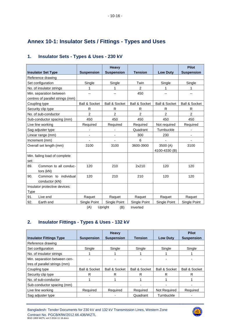
- 10-16 -
Bangladesh: Tender Documents for 230 kV and 132 kV Transmission Lines, Western Zone
Contract No. PGCB/KfW/2012.66.436/WZTLBGD 1800 WZTL vol 2 2016 11 16.docx
Annex 10-1: Insulator Sets / Fittings - Types and Uses
1. Insulator Sets - Types & Uses - 230 kV
Insulator Set Type Suspension
Heavy
Suspension Tension Low Duty
Pilot
Suspension
Reference drawing
Set configuration Single Single Twin Single Single
No. of insulator strings 1 1 2 1 1
Min. separation between
centres of parallel strings (mm)
-- -- 450 -- --
Coupling type Ball & Socket Ball & Socket Ball & Socket Ball & Socket Ball & Socket
Security clip type R R R R R
No. of sub-conductor 2 2 2 2 2
Sub-conductor spacing (mm) 450 450 450 450 450
Live line working Required Required Required Not required Required
Sag adjuster type - - Quadrant Turnbuckle -
Linear range (mm) - - 300 230 -
Increment (mm) - - 6 - -
Overall set length (mm) 3100 3100 3600-3900 3500 (A)
4100-4330 (B)
3100
Min. failing load of complete
set:
89. Common to all conduc-
tors (kN)
120 210 2x210 120 120
90. Common to individual
conductor (kN)
120 210 210 120 120
Insulator protective devices:
Type
91. Live end Raquet Raquet Raquet Raquet Raquet
92. Earth end Single Point Single Point Single Point Single Point Single Point
(A) Upright (B) Inverted
2. Insulator Fittings - Types & Uses - 132 kV
Insulator Fittings Type Suspension
Heavy
Suspension Tension Low Duty
Pilot
Suspension
Reference drawing
Set configuration Single Single Single Single Single
No. of insulator strings 1 1 1 1 1
Min. separation between cen-
tres of parallel strings (mm)
- - - - -
Coupling type Ball & Socket Ball & Socket Ball & Socket Ball & Socket Ball & Socket
Security clip type R R R R R
No. of sub-conductor 1 1 1 1 1
Sub-conductor spacing (mm) - - -
Live line working Required Required Required Not Required Required
Sag adjuster type - - Quadrant Turnbuckle -

- 10-17 -
Bangladesh: Tender Documents for 230 kV and 132 kV Transmission Lines, Western Zone
Contract No. PGCB/KfW/2012.66.436/WZTLBGD 1800 WZTL vol 2 2016 11 16.docx
Insulator Fittings Type Suspension
Heavy
Suspension Tension Low Duty
Pilot
Suspension
Linear range (mm) - - 75 - 225 230 -
Increment (mm) - - - - -
Overall set length (mm) 2000 2000 2400 2350 (A)
2900 (B)
1950
Min. failing load complete set
93. Common to all conduc-
tor (kN)
70 120 120 70 70
94. Common to individual
Conductor (kN)
70 120 120 70 70
Insulator protective devices:
Type
95. Live end Single Point Single Point Single Point Single Point Single Point
96. Earth end Single Point Single Point Single Point Single Point Single Point
(A) Upright (B) Inverted
Annex 10-2: Earthwire/OPGW Sets - Types & Uses
1. 230 kV
Earthwire/OPGW Set Type Suspension Tension
Reference drawing
Overall set length (mm) 350 700
Min. failing load complete set (kN)* 70 120
* - Strength may be modified
2. 132 kV
Earthwire/OPGW Set Type Suspension Tension
Reference drawing
Overall set length (mm) 350 700
Min failing load complete set (kN)* 70 120
* - Strength may be modified

- 10-18 -
Bangladesh: Tender Documents for 230 kV and 132 kV Transmission Lines, Western Zone
Contract No. PGCB/KfW/2012.66.436/WZTLBGD 1800 WZTL vol 2 2016 11 16.docx
Annex 10-3: Conductor Joints & Clamps - Types & Uses
1. 230 kV
Joint & Clamp Type
Conductor Earthwire
795 MCM ACSR Mallard 7 x 4.0 S equiv. OPGW 7 x 4.0 GS Earthwire
Suspension clamp type Trunnion Corona Free Armour grip Trunion
Armour rods Preformed type required
for 230 kV
210kN suspension sets.
Not required for other sets
Not required Not required
Counterweights (kg) 40-80-120
Tension joints:
97. Dead end type Compression Helical Compression
98. Jumper terminal
type
Compression
99. Mid-spans type Compression Compression
Repair sleeves type Compression/Helical Compression/Helical Compression/Helical
Tee connectors type Compression Compression
Non-tensile joints:
100. Disconnectable
101. Non-disconnectable
Jumper palms type Bolted 0° & 30°
Line termination fittings
type
Weighted spacers
Jumper weights (kg) 3 x 35
Tubular jumpers
Earthwire bonds - end fit-
ting type
Pin-lug
Lug-lug
Lug-lug
2. 132 kV
Joint & Clamp Type Phase OPGW
Conductor 636 MCM ACSR Grosbeak 7 x 3.25 S equiv.
Suspension clamp type Trunnion Corona free Armour Grip
Armour rods Preformed type-required for 132kV, 120kN suspension
set; not required for other sets
Required
Counterweights (kg) 50
Tension joints:
102. Dead end type Compression Helical
103. Jumper terminal type Compression
104. Mid-spans type Compression
105. Repair sleeves type Compression
106. Tee connectors type Compression
Non-tensile joints:
107. Disconnectable
108. Non-disconnectable

- 10-19 -
Bangladesh: Tender Documents for 230 kV and 132 kV Transmission Lines, Western Zone
Contract No. PGCB/KfW/2012.66.436/WZTLBGD 1800 WZTL vol 2 2016 11 16.docx
Joint & Clamp Type Phase OPGW
Jumper palms type Bolted 0° & 30°
Line termination fittings type
Jumper weights (kg)
Tubular jumpers
Earthwire bonds end fitting type Lug-lug
Annex 10-4: Engineering Documents to be Submitted by Contractor
Clause Reference Document Description Comment
10.4.1 Insulator & conductor fittings - contract drawings
10.4.3 Installation procedures
10.6.1 Insulator & conductor fittings - type test certificate If requested
10.6.1 Type test - programme & procedures
10.7.15 Galvanizing test results If requested
10.7.16 Ingot zinc certificates If requested
10.7.16 Metallic & bolt/nuts material test certificate If requested
10.7.16 Insulator & conductor fittings - type test results
10.7.16 Insulator & conductor fittings - sample test results
10.7.16 Insulator & conductor fittings - routine test results If requested
10.7.17 Certificates of conformity
Annex 10-5: Notification and Hold Points
Clause Reference Notification Points Hold Points
10.4.1 Contract drawings
10.6.1 Insulator and conductor fittings - type tests
10.7.13 Insulator & conductor fittings -
sample tests

- 10-20 -
Bangladesh: Tender Documents for 230 kV and 132 kV Transmission Lines, Western Zone
Contract No. PGCB/KfW/2012.66.436/WZTLBGD 1800 WZTL vol 2 2016 11 16.docx
Annex 10-6: Reference Standards
The reference standards and other documents referred to in this section of the specifications are
listed below:
IEC 60120: Dimensions of ball and socket couplings of string insulator units
IEC 60372: Locking devices for ball and socket couplings of string insulator units
Dimensions and tests
IEC 60471: Dimensions of clevis and tongue couplings of string insulator units
IEC 61284: Overhead lines Requirements and tests for fittings
BS EN 13411 Specification for thimbles for wire rope
BS EN ISO 1461 Specification for hot-dipped galvanising coating on iron and steel arti-
cles
BS 970: Specification for wrought steel for mechanical and applied engineer-
ing purposes
BS EN 10084; BS EN 10085;
BS EN 10087; BS EN 10095;
BS EN 10250; PD 970;
BS 1387:
Specification for screwed and socketed steel tubes and tubular and
for plain end steel tubes suitable for welding or screwing to BS 21
pipe threads
BS EN 515: Specification for wrought aluminium and aluminium alloy
BS EN 573; BS EN 586;
BS EN 603; BS EN 604;
BS EN 1559:
Specification for aluminium and aluminium alloy ingots and castings
for general engineering purposes
BS EN 1676; BS EN 1706;
BS 1574:
Specification for split cotter pins
BS EN 1563: Specification for spheroidal graphite cast iron
BS EN 1172: Specification for rolled copper and copper alloys: Sheet strip and foil
BS EN 1652; BS EN 1653;
BS EN 1654; BS EN 50183
Aluminium alloy stranded conductors for overhead power lines
BS 3643: ISO Metric threads
Part 2: Limits and tolerances for course pitch series threads
BS 3692: Specification for ISO Metric Precision hexagon bolts, screws and nuts
BS 4190: Specification for ISO Metric hexagon bolts, screws and nuts
BS 4320: Specification for metal washers for general engineering purposes.
Metric series
BS 4429: Specification for rigging screws and turnbuckles for general engineer-
ing, lifting purposes and pipe hanger applications
BS 4464: Specification for Spring Washers for general engineering and auto-
mobile purposes. Metric series.

- 10-21 -
Bangladesh: Tender Documents for 230 kV and 132 kV Transmission Lines, Western Zone
Contract No. PGCB/KfW/2012.66.436/WZTLBGD 1800 WZTL vol 2 2016 11 16.docx
BS 4579: Part 3 Performance of Mechanical and Compression Joints in Electric
Cables and Wire Connectors
BS EN 1011: Specification for arc welding of carbon and carbon manganese steel
BS EN 1562: Specification for Malleable cast iron
BS EN 1676: Aluminium and aluminium alloys - Alloyed ingots for remelting.
BS EN 1179: Zinc and Zinc Alloys.
BS EN 10025: Specification for hot rolled products of non-alloy structural steels and
their technical delivery requirements.
BS EN 50341-1: 2012 Overhead electric lines exceeding AC 1 kV - Part 1: General require-
ments - Common specifications

- 11-1 -
Bangladesh: Tender Documents for 230 kV and 132 kV Transmission Lines, Western Zone
Contract No. PGCB/KfW/2012.66.436/WZTLBGD 1800 WZTL vol 2 2016 11 16.docx
11. Conductors
11.1 Scope
11.1.1 Types and Uses
The type and configuration of the phase conductor and earthwire shall be in accordance with the re-
quirement of this specification. For types of conductor reference should be made to Annex 11-1.
11.1.2 Definition
The following definitions are used throughout this specification:
AAC All Aluminium Conductor
AAAC All Aluminium Alloy Conductors
ACSR Aluminium Conductor Steel Reinforced
ACAR Aluminium Conductor Alloy Reinforced
AACSR Aluminium Alloy Conductor Steel Reinforced
ACSR/AW Aluminium Conductor Aluminium clad steel reinforced
S Galvanised Steel Conductor
SA Aluminium clad steel conductor
11.1.3 Sub-conductor Configuration
For details of sub-conductor configuration and spacing reference should be made to Annex 11-2.
11.1.4 Optical Fibre Cable
For details of embedded optical fibre cable reference should be made to Section 14 of this specifica-
tion.
11.2 Design
11.2.1 General
All AAC, AAAC, ACSR, AACAR and AACSR conductors shall comply with the requirements of IEC
61089. Where applicable the selection of parameters not quantified nor specified in IEC 61089, refer-
ence shall be made to the appropriate standard Specification stated in Annex 11-1.
The design of non-standard conductors including thermal resistant, fibre optic earthwire and those in-
corporating shaped wire sections shall be submitted to the Employer. This is a Hold Point.

- 11-2 -
Bangladesh: Tender Documents for 230 kV and 132 kV Transmission Lines, Western Zone
Contract No. PGCB/KfW/2012.66.436/WZTLBGD 1800 WZTL vol 2 2016 11 16.docx
11.2.2 System Loading Conditions
Reference should be made to Annex 11-3 for details of the applicable phase conductor and earthwire
system loading.
11.3 Materials
11.3.1 Conductors
11.3.1.1. Aluminium wire used for AAC, ACSR, ACAR, and ACSR/AW or incorporated in fibre optic
earthwire shall comply with the requirements of IEC 60889. The aluminium shall be of the highest puri-
ty commercially obtainable, the copper content shall not exceed 0.04%.
11.3.1.2. Aluminium alloy wire used for AAAC, AACSR or incorporated in fibre optic earthwire shall
comply with the requirements of IEC 60104. The copper content shall not exceed 0.05%. Galvanised
steel core wire used for ACSR and AACSR shall comply with the requirements of IEC 60888. Alumini-
um clad steel wire for ACSR/AW, SA or incorporated in fibre optic earthwire shall comply with the re-
quirements of IEC 61232.
11.3.1.3. Shaped aluminium or aluminium alloy wire sections shall conform to the requirements of
the appropriate IEC standard. Galvanised steel earthwire shall comply with the requirements of IEC
60888.
11.3.2 Conductor Grease
All grease applied to the specified inner aluminium, aluminium alloy or steel strands of the conductor
shall be of a neutral type and shall have the following properties:
a. The grease shall protect the conductors from corrosion in service which may include operation
in atmospheres containing salt spray or industrial pollution;
b. The grease shall not corrode steel, aluminium or aluminium alloy wires or any combination of
wires;
c. The grease shall be compatible with any wire drawing lubricant present on the conductor wires.
d. The grease or any component of the grease shall not flow within, nor exude from the conductor
during storage, transport, erection or during service at temperatures up to 100°C;
e. The grease shall retain its properties at all operating temperatures specified in Annex 11-1;
f. The grease shall not be damaged by storage or by the conductor manufacturing process (hot
applied grease shall be unimpaired after heating to 20° C above its dropping point for 150
hours, or 10°C above the temperature reached during the application of the grease to the con-
ductor, whichever is greater);
g. The grease shall have adequate resistance to oxidation;
h. The grease shall not present a health hazard and shall conform to relevant current health and
safety requirements.

- 11-3 -
Bangladesh: Tender Documents for 230 kV and 132 kV Transmission Lines, Western Zone
Contract No. PGCB/KfW/2012.66.436/WZTLBGD 1800 WZTL vol 2 2016 11 16.docx
11.4 Workmanship
Precautions shall be taken during the manufacture, storage and delivery of conductors to prevent con-
tamination by copper or other materials which may adversely affect the aluminium or aluminium alloy.
Where permitted in IEC 61089 for aluminium or aluminium alloy wires the preferred method of jointing
single wires is cold pressure welding.
11.5 Protective Treatment
11.5.1All steel core wires unless specified to the contrary shall be hot-dipped galvanised to comply
with the requirements of IEC 60888.
11.5.2Aluminium clad steel shall comply with the requirements of IEC 61232.
11.5.3Unless specified to the contrary all conductors shall be uniformly covered with a neutral grease
(i.e. as case 2 appendix C IEC 61089). The minimum fill factor of the grease shall not be less than
70%. Each layer of wire except the outer layer shall have, both lengthwise and peripherally, an even
and continuous coating of grease. Wax thickened greases shall be applied at a temperature above the
dropping point, and shall be substantially free from contaminants. No grease must be visible on the
exterior of the conductor and every effort should be made to minimize the presence of drawing oil on
the surface of the finished conductor.
11.6 Conductor Erection
11.6.1 Method Statement
The Contractor shall provide the Engineer with a method statement giving sequential details of the
conductor stringing, sagging, jointing, clamping-in etc. methods and including his intended program.
Full tension stringing shall be undertaken, unless otherwise agreed in writing by the Engineer.
The method statement shall be submitted to the Employer for acceptance the requisite period before
conductor stringing commences. This is a Hold Point.
11.6.2 Conductor Lengths and Joints
The fullest possible use shall be made of the maximum conductor lengths in order to reduce to a min-
imum the number of mid-span joints. The number, span and location of any phase conductor or
earthwire mid-span joints used on the line shall be approved by the Employer. There shall not be more
than one such joint per conductor in any one span. A conductor schedule detailing the lengths of con-
ductors and positions of mid-span joints in the section, shall be submitted to the Employer for approv-
al; this requisite period before conductor stringing commences. This is a Hold Point.

- 11-4 -
Bangladesh: Tender Documents for 230 kV and 132 kV Transmission Lines, Western Zone
Contract No. PGCB/KfW/2012.66.436/WZTLBGD 1800 WZTL vol 2 2016 11 16.docx
Mid-span joints shall not be used:
a. Within 3m of the conductor suspension clamp or tension joint (dead end).
b. In sections between tension towers of less than three spans unless specifically approved.
c. In spans over railways, navigable rivers, main roads, trunk routes, buildings or spans covered
by special wayleave conditions. A line shall be deemed to be over a building when, at the speci-
fied maximum conductor temperature with an assumed conductor swing of 45 degrees from the
vertical, any part of the building is vertically below any conductor.
d. In any span immediately adjacent to a span as described in (c), unless the tower between such
span and adjacent spans is fitted with tension insulator sets.
11.6.3 Repair Sleeves
In the case of local damage to individual wires of a conductor during erection, repair sleeves may be
permitted with the approval of the Employer and subject to no repair sleeve being nearer than 1.2 m
from any conductor fitting other than spacer dampers. This is a Hold Point.
11.6.4 Line Terminations
Line termination fittings either bimetallic or aluminium shall be fitted as specified at line terminations, to
provide the connection interface between the downleads and/or downdroppers and the substation
equipment and/or cable sealing ends.
11.6.5 Inelastic Extensions of Conductors
The Contractor shall be responsible for evaluating the inelastic extension which is likely to occur in the
conductor over the defined period of years. Reference shall be made to the recommendations con-
tained in CIGRE Electra No. 75 for the evaluation. Compensation for the inelastic extensions so de-
termined shall be made by the selection and use of an optimum pretension and time period and over
tensioning the conductor at the time of erection. Over tensioning of the conductor shall be made by
an allowance in the erection temperature i.e. sagging temperature equals conductor temperature mi-
nus equivalent temperature correction. However, it should be noted that the maximum conductor ten-
sion under the defined system loading must not be exceeded at the time the transmission line is
handed over.
The Contractor shall ensure that the erection tensions do not exceed the appropriate system loading
on the supports. The Contractor's proposals shall be submitted to the Employer in conjunction with the
erection sags and tensions.
11.6.6 Sags and Tensions
11.6.6.1 The Contractor shall prepare sag and tension calculations and schedules for the phase
conductor and earthwire for every span at the proposed range of sagging operations, the design load-
ing condition and at the maximum conductor operating temperature.

- 11-5 -
Bangladesh: Tender Documents for 230 kV and 132 kV Transmission Lines, Western Zone
Contract No. PGCB/KfW/2012.66.436/WZTLBGD 1800 WZTL vol 2 2016 11 16.docx
11.6.6.2 Due allowance shall be made for any severe gradient in the transmission line route, in
addition the suspension insulator sets shall be vertical at the specified temperature immediately after
stringing.
11.6.6.3 These schedules shall be submitted to the Employer the requisite period prior to the
commencement of conductor stringing and for inclusion within the supply and install manual. This is a
Hold Point.
11.6.7 Conductor Stringing
11.6.7.1. The Contractor shall take special care that during the stringing of the phase conductor
and earthwire to ensure that no contact is made with the ground or any obstacles such as walls, fenc-
es, or buildings etc., nor shall they be over-strained during this process.
11.6.7.2. Drum battens shall not be removed until conductor drums are properly mounted at the
drum station on the line and the battens shall be immediately refitted to the drums if any surplus con-
ductor is left thereon. Drums will be transported and positioned on station with the least possible
amount of rolling.
11.6.7.3. Approved means shall be provided to prevent any damage to conductors where they are
run over temporary supports.
11.6.7.4. The conductors, joints and clamps shall be erected in such a manner that no bird cag-
ing, over- tensioning of individual wires or layers, or other deformation, or damage to the conductors
shall occur.
11.6.7.5. Clamps or hauling devices shall, under erection conditions, allow no relative movement of
strands or layers of the conductor. If required by the Employer, this property shall be demonstrated
by actual tests.
11.6.7.6. The Contractor shall at his own expense make suitable arrangements for temporary guy-
ing of supports where necessary. Suitable plates (detachable or otherwise) shall be provided on the
supports for the attachment of any temporary guys. The additional loads imposed on specific
support during conductor stringing by the use of temporary guys shall be calculated and submitted to
the Employer for appraisal prior to conductor stringing commencing. This is a Hold Point.
11.6.7.7. Each conductor shall be clamped in at suspension points and the adjacent spans fitted
with spacer dampers or vibration dampers at a concurrent operation, after having been sagged and
tensioned off at section supports. The maximum time period between clamping-in and fitting of spacer
dampers or vibration dampers shall not exceed 36 hours, or such other time agreed with the Engineer.
11.6.7.8. If this period is exceeded the Employer reserves the right to undertake a random inspec-
tion of the unclamped and lowered conductor and if necessary the cutting out and replacement of any
suspect conductor. All expenses involved in the unclamping, conductor lowering, conductor replace-
ment and re-sagging of the conductor shall be borne by the Contractor, whether or not any damage is
found.

- 11-6 -
Bangladesh: Tender Documents for 230 kV and 132 kV Transmission Lines, Western Zone
Contract No. PGCB/KfW/2012.66.436/WZTLBGD 1800 WZTL vol 2 2016 11 16.docx
11.6.8 Running Out Blocks
11.6.8.1 Conductor running out blocks shall be free running on ball or roller bearings and of an
approved design to avoid damage to the conductor. The blocks shall have an electrical conducting
path between their suspension fittings and the conductors supported by the blocks.
11.6.8.2 If conductors are being erected on one circuit of a double circuit line with the other circuit
live or in other situations likely to induce a voltage into the conductor all running-out blocks shall be
bonded to the support steelwork by means of flexible connections approved by the Employer.
11.6.8.3 The diameter of the running out block shall not be less than 20 times the diameter of the
respective conductor. Alternatively, where a group of smaller blocks are used these shall be arranged
such that the conductor passes over an equivalent radius of not less than 20 times the conductor di-
ameter.
11.6.8.4 The hangers for the running out blocks should be of a uniform length so that the conduc-
tors and the sheaves are held at a uniform distance, not exceeding 500 mm above, or below their final
position when clamped in.
11.6.9 Sagging
The Contractor shall use approved dynamometers, accurate sighting and/or other apparatus neces-
sary for the proper checking of the work. Every section shall be offered to the Employer for inspection
of the results before sagging equipment, dynamometers, sighting or other apparatus is removed from
that portion of the Works. This is a Notification Point.
The assumed temperature of the conductor for the purposes of sagging, will be determined from an
accurate thermometer basket suspended clear of the support steelwork at a point adjacent to the bot-
tom crossarm level of one support at one end of the span being used to control sagging. The basket
shall have been in position 15min before temperature reading is taken.
11.6.10 Earthing of Conductor During Erection (Safety)
During the erection of conductors and subsequently when any work is being carried out on the support
above the anti-climbing device level, the Contractor shall ensure the conductors are adequately
earthed at points not more than three spans apart, or such other spacing as may be necessary or di-
rected by the Employer.
The earthing equipment shall be approved by the Employer and shall be designed to be clearly visible
from the ground.
11.6.11 Crossings Over Roads, Railways, Buildings, Structures, etc.
Where the transmission line crosses over roads or tracks liable to be used by traffic of any description,
or railways, buildings, structures and obstacles of any kind the Contractor shall provide temporary
scaffolding during stringing operations. Scaffolding in accordance with this Clause and Clause 5.5.3
shall be of adequate construction and height. Drawings and supporting calculations shall be submitted
to the Employer and governmental or statutory bodies. This is a Hold Point.

- 11-7 -
Bangladesh: Tender Documents for 230 kV and 132 kV Transmission Lines, Western Zone
Contract No. PGCB/KfW/2012.66.436/WZTLBGD 1800 WZTL vol 2 2016 11 16.docx
11.6.12 Live Line Scaffolds
Where it is possible only to have a restricted outage on a distribution or a transmission line sufficient
only to erect the upper portion and 'net' the scaffold a live-line scaffold shall be used. Live line scaf-
folds shall be in accordance with the requirements of Clause 5.5.5. Drawings and supporting calcula-
tions shall be submitted to the Employer and governmental or other statutory bodies. This is a Hold
Point.
11.6.13 Downleads
Downlead spans between terminal supports and substation anchor points shall be erected at reduced
tensions in accordance with Clause 8.2.12. Downleads shall be considered as slack span.
The Contractor shall include within his method statement details of his proposal for tensioning down-
leads.
11.6.14 Conductor Cutting
Conductor joints shall be made over protective sheeting and waste materials shall be removed from
site. Cutting of layers of conductors shall be carried out with tools designed to prevent damage to un-
derlying strands. Preparation prior to jointing shall be carried out in accordance with Clause 11.6.15.
11.6.15 Jointing
11.6.15.1. Before the conductor is inserted into compression type joints, clamps, connectors, com-
pression spacers or repair sleeves, it shall be prepared in the following manner, using an approved
grease for phase conductors and earthwires.
11.6.15.2. The Contractor shall include within his Method Statement full details of his proposed joint-
ing procedures, including where necessary appropriate diagrams.
a. New Conductor: The outer layer of the conductor throughout the whole length of the joint shall
be wiped clean, coated with grease, wire brushed (stainless steel) through the grease which
shall be left on and assembled in the fitting after a further libreal application of grease.
b. Old Conductor: Where a compression joint is to be made on to old conductor the Employer
shall be given the requisite period of notice. This is a Notification Point.
11.6.15.3. Unless otherwise agreed with the Employer who will take account of the degree of corro-
sion of the conductor, all the aluminium layers, after preliminary cleaning of the individual aluminium
wires with a fine grade of abrasive paper or cloth, shall be coated with grease, wire brushed through
the grease which shall be left on and assembled in the fitting after a further libreal application of
grease. The innermost layer of aluminium wires should not be unlaid but treated on their external sur-
faces only. Care shall be taken to avoid damage to the wires especially by kinking or excessive re-
moval of metal. If however, damage does occur the whole conductor shall be cut clear of the damage
and as a fresh joint prepared.

- 11-8 -
Bangladesh: Tender Documents for 230 kV and 132 kV Transmission Lines, Western Zone
Contract No. PGCB/KfW/2012.66.436/WZTLBGD 1800 WZTL vol 2 2016 11 16.docx
11.6.15.4. All compression joints shall be fitted strictly in accordance with the manufacturer's instruc-
tions. During compression all dies shall fully close at each end of the bite and the bites shall overlap
by a minimum of 5 mm. All flashes shall be removed.
11.6.16 Surface Greasing of Conductor
Except where specified to the contrary, the conductor shall be coated with an approved grease at the
point of attachment of fittings immediately before the final assembly of any fittings and all surplus
grease shall be removed after assembly.
11.6.17 Greasing of Bolted Interfaces
11.6.17.1. For bolted jumper connections, non-tension joints, tee connectors and bonding leads, the
lug and clevis contact faces shall be greased with an approved grease, wire brushed through the
grease libreally before assembly. All nuts and bolts shall be tightened to the supplier's recommended
torque.
11.6.17.2. Where jumper or non-tension joint bolts are found to be loose the Contractor shall dis-
mantle and re- assemble the joint as above before re-bolting and tightening.
11.6.17.3. All bolts shall face towards the centre line of each conductor bundle.
11.6.18 Inspection Holes
Where a tension joint is supplied with an inspection hole the aluminium alloy drive screw shall be
hammered in firmly until smooth and flush with the surface of the aluminium sleeve using the flat face
of a hammer. Final smoothing over may be carried out using a flat file if necessary.
11.6.19 Tension Support Jumpers
11.6.19.1. All tension support jumper loops shall be erected complete with all fittings in accordance
with the approved wire clearance diagram.
11.6.19.2. Where quadruple bundle sub conductors are specified a reduced spacing twin spacer
shall be fitted on the lowest pair of the jumper sub-conductors. They shall be adjusted on site to
give the best possible clearance to prevent contact between the phase and jumper sub-conductors.
11.6.19.3. Where specified bonding spacers shall be located at a point suitable for the application of
temporary earthing bonds, normally near the middle of the jumper. In the case of non-tension joint
bonding spacers the conductors must butt in the centre. Jointing shall be in accordance with the re-
quirements of Clause 11.6.15 and resistance measurement in accordance with Clause 11.7.9.
11.6.19.4. Where tubular jumpers are fitted, the earthing bar shall be arranged as near as practical
to a step-bolt of the support.

- 11-9 -
Bangladesh: Tender Documents for 230 kV and 132 kV Transmission Lines, Western Zone
Contract No. PGCB/KfW/2012.66.436/WZTLBGD 1800 WZTL vol 2 2016 11 16.docx
11.6.20 Spacer Dampers
Spacer dampers where specified shall be fitted to the phase conductors strictly in accordance with the
manufacturer's instructions.
Where there is a mid-span joint or repair sleeve on a conductor, the adjacent spacer damper must not
be closer than 2 m, or further away than 12 m from the mid-span joint or repair sleeve. If possible, this
should be achieved using the correct configuration of spacer damper positions. This configuration can
be used in reverse by taking the measurement from the other support. Where the configuration given
does not allow a spacer damper to be in the correct juxtaposition with the mid-span joint or repair
sleeve an additional spacer damper should be fitted.
11.6.21 Vibration Dampers
Vibration dampers shall be fitted to the earthwires and where specified the phase conductors, strictly
in accordance with the manufacturer's instructions.
11.6.22 Aircraft Warning Spheres
Where specified aircraft warning spheres shall be fitted to the earthwires, complete with factory
formed helical armour rods. The spheres shall, be located in accordance with the requirements of
ICAO Annex 14 unless specified to the contrary.
11.6.23 Earthwire Bonds
Flexible earthwire bonds in accordance with the requirements of clause 10.2.20 shall be fitted between
all earthwire suspension and tension sets and the support. Where OPGW is used the connection to
the earthwire shall if necessary be via a 'C' type connector (ref. clause 10.2.19).
No bond is required at terminal support positions where the earthwire jumper shall be attached di-
rectly to the support. At other tension positions the earthwire shall be continuously jumpered through.
Where OPGW is used the jumper shall be formed from a short length of equivalent conductor attached
to the earthwire via a 'C' type connector.
11.7 Quality Control
11.7.1 Conductors
11.7.1.1 Sample tests shall be undertaken on all conductors in accordance with the requirements
of IEC 61089 as applicable and this specification. This is a Notification Point.
11.7.1.2 The mechanical tests shall be taken on straightened samples of individual wires taken af-
ter conductor stranding. In the event of the sample from any length not passing the mechanical or re-
sistance tests, a second and third sample shall be taken from the same length, and if one of these al-
so fails under test, the length of conductor (i.e. drum) from which it has been taken shall be rejected.
- 11-10 -
Bangladesh: Tender Documents for 230 kV and 132 kV Transmission Lines, Western Zone
Contract No. PGCB/KfW/2012.66.436/WZTLBGD 1800 WZTL vol 2 2016 11 16.docx
For the ductility tests, should any variation occur in the results between the torsion and elongation
methods of testing the results of the torsion test shall prevail.
11.7.1.3 In the event of any machinery used for conductor manufacture being used for materials,
other than aluminium, galvanized or aluminium clad steel, the manufacturers shall furnish the Employ-
er with a certificate stating that the machinery has been thoroughly cleaned before use on aluminium,
aluminium alloy, galvanized or aluminium clad steel wire and that the conductor is free from contami-
nation.
11.7.2 Grease
11.7.2.1. The manufacturer's type test proposals for proving compliance with this specification with
regard to the following grease properties shall be submitted to the Employer. This is a Hold Point.
a. dropping point tests;
b. thermal history test;
c. reversibility;
d. oxidation;
e. corrosive substances in grease;
f. anti-corrosion properties;
g. complete conductor test, to ensure that the grease does not appear through the outer wires at
less than the specified temperature.
11.7.2.2. Sample tests on grease shall be undertaken at the same time as sample tests on the
conductor. The mass and length of the conductor sample shall be measured and recorded. The sam-
ple shall be inspected to ascertain that no grease is visible on the exterior. The wires shall then be
separated progressively layer by layer whilst being inspected to verify the coating requirements are
met.
11.7.2.3. Grease for the dropping test shall be removed without heating, the remaining grease may
then be removed by a convenient method. The mass of the cleaned conductor sample shall be deter-
mined and recorded. The mass of grease shall be determined from the difference in masses and shall
be recorded.
11.7.2.4. The mass of grease per unit length of conductor shall not be less than the minimum value
given in Annex 11-1.
11.7.2.5. All drums of conductor shall be routinely inspected for traces of visible grease on the ex-
terior of the conductor.
11.7.3 Galvanizing
Tests for galvanized steel wire shall be carried out at the works to ensure compliance with the re-
quirements of IEC 60888. Details of the test results shall be made available to the Employer upon re-
quest.

- 11-11 -
Bangladesh: Tender Documents for 230 kV and 132 kV Transmission Lines, Western Zone
Contract No. PGCB/KfW/2012.66.436/WZTLBGD 1800 WZTL vol 2 2016 11 16.docx
11.7.4 Aluminium Clad Steel
Tests for aluminium clad steel wire shall be carried out at the works to ensure compliance with the re-
quirements of IEC 61232. Details of the test results shall be made available to the Employer upon re-
quest.
11.7.5 Test Certificate
All metallic materials used in the manufacture of conductors shall be covered by test certificates stat-
ing their mechanical and chemical properties to prove compliance with this specification and IEC as
appropriate. These certificates shall be made available to the Employer upon request.
Test records covering type and sample tests shall be made available to the Employer.
11.7.6 Certificate of Conformity
When requested copies of the following certificate/records shall also be forwarded:
a. metallic material test certificate;
b. conductor stranding equipment non contamination certificate;
c. galvanizing test records;
d. ingot zinc certificate;
e. aluminium cladding test records.
11.7.7 Sagging Tolerance
Immediately after the conductors have been sagged and clamped in, the mean sag of the conductors
forming any phase shall not differ from the calculated erection sag by more than 4% and the sub- con-
ductors forming each phase conductor bundle shall not differ from each other by more than 40 mm. In
addition the sag of any one phase shall not differ by more than 150 mm from the mean sag of all
phases in the same span. The linear adjustment available on the sag adjusters, unless specified to the
contrary, at the end of the maintenance period shall not be less than ±75 mm.
11.7.8 Jointing Competence
Tension and non-tension compression joints, repair sleeves, tee connectors and bimetallic connectors
shall be fitted to the conductors only by linesmen whom the Contractor possess written approval of
their Jointing Competence issued by the Employer. Where necessary the Contractor shall arrange for
the appropriate tests to be witnessed by the Employer allowing the requisite period of notice. This is a
Hold Point.
11.7.9 Electrical Resistance of Joints and Clamps
The maximum resistance, measured overall (primary measurement), of all joints shall not exceed 75%
of the resistance of an equivalent length of conductor.

- 11-12 -
Bangladesh: Tender Documents for 230 kV and 132 kV Transmission Lines, Western Zone
Contract No. PGCB/KfW/2012.66.436/WZTLBGD 1800 WZTL vol 2 2016 11 16.docx
11.7.10 Bolt Tightness
The Contractor shall be responsible for checking that the bolts in all fittings including spacers, spacer
dampers, vibration dampers etc., have been correctly tightened to the Supplier's recommended torque
value. A record of this work shall be kept and made available to the Engineer upon request.
11.7.11 Clearances
Clearance between phase conductors, including jumpers and ground and between jumpers and sup-
port structures shall be checked during erection and before handing over the line.
11.7.12 Final Inspection
Immediately prior to hand over of the transmission line, the Contractor shall conduct a final line route
inspection to ensure that the specified clearances are available to all supports, ground etc. all tempo-
rary earthings have been removed and that extraneous objects are removed. This is a Notification
Point.
Where specified after the final route inspection the Contractor shall demonstrate by means of a low
voltage test, to the complete satisfaction of the Employer, that there is complete continuity over each
phase. This is a Hold Point.
11.7.13 Records
During the course of the work, the SIMM document (reference Clause 4.7) shall be updated with de-
tails of the actual phase conductor and earthwire erection sags, location of phase conductor and
earthwire tension joints including repair sleeves and the electrical resistance of all joints and clamps
including the name of the linesman responsible and the date of assembly.

- 11-13 -
Bangladesh: Tender Documents for 230 kV and 132 kV Transmission Lines, Western Zone
Contract No. PGCB/KfW/2012.66.436/WZTLBGD 1800 WZTL vol 2 2016 11 16.docx
Annex 11-1: Conductor - Types and Uses
1. 230 kV
Conductor Phase Earthwires
Designation
(Code Name)
Mallard
(230KV)
OPGW
7 x 4.0 S equiv.
GS
7 x 4.0
Type ACSR "A" "G.S."
Reference standards ASTM B232 IEC 61089 IEC 61089
Aluminium alloy grade
Steel grade
-
-
as appropriate -
11,5
Galvanising Thickness - - -
Aluminium class (AS wire) Ref IEC 61232 - -
Aluminium type (AS wire) - 20 % IACS
Conductor operating temperature range (°C) 5-80 - -
Minimum mass of grease (kg/km) - - -
Creep period of conductor to be considered (years) 20 - 20
No. and diameter of wire (No./mm) A1. 30/4.135,
St. 19/2.482
- 7/4.0 GS
Overall diameter (mm) 28.95 12.34
Nominal breaking load (kN) 171.25 101.41
Weight (kg/km) - -
Direction of external lay Right hand Right hand Right hand
Notes:
i. ACSR conductor shall be applied with grease in all layers for protection of steel from corrosion
according to the relevant standard.
ii. "A" Maximum diameter of OPGW must not exceed the diameter and mass of earthwire.
2. 132 kV
Conductor Phase Earthwires
Designation (Code Name) Grosbeak OPGW
7x3.25 GS equiv.
GS
7 x 4.0
Type ACSR "A" "G.S."
Reference standards ASTM B232 IEC 61089 IEC 61089
Aluminium Alloy Grade
Steel Grade
-
-
as appropriate -
11,5
Galvanising Thickness - - -
Aluminium class (AS wire) Ref IEC 61232 - -
Aluminium type (AS wire) - 20 % IACS
Conductor operating temperature range (°C) 5-80 - -
Minimum mass of grease (kg/km) - - -
Creep period of conductor to be considered (years) 20 - 20
Number and diameter of wire (no./mm) A1. 26/3.973
St. 7/3.089
- 7/4.0 GS

- 11-14 -
Bangladesh: Tender Documents for 230 kV and 132 kV Transmission Lines, Western Zone
Contract No. PGCB/KfW/2012.66.436/WZTLBGD 1800 WZTL vol 2 2016 11 16.docx
Conductor Phase Earthwires
Overall diameter (mm) 25.16 - 12.34
Nominal breaking load (kN) 112 - 101.41
Weight (kg/km) - - -
Direction of external lay Right hand Right hand Right hand
Notes:
i ACSR conductor shall be applied with grease in all layers for protection of steel from corrosion
according to the relevant standard.
ii. "A" Maximum diameter of OPGW must not exceed the diameter and mass of earthwire.
Annex 11-2: Subconductor Configuration (230 kV)
Configuration Spacing (mm x mm) Orientation Notes
Twin 450 Horizontal 230 kV
Annex 11-3: Portion Conductor System Loading
1. 230 kV Conductor System Loading
Conductor Unit Phase Earthwire
Code Name ACSR Mallard OPGW 7x4.0 S
Equiv.
GS 7 x 4.0
Maximum Working Tension Conditions (MWT)
Maximum allowable tension kN as per tower section
Wind pressure N/m² as per tower section
Temperature °C 5 5 5
Every-day conditions (still air):
Maximum tension kN as per tower section
Temperature °C as per tower section
Erection Conditions (still air)
Max. tangential tension kN n.a. n.a. n.a.
Temperature °C
Sagging limits of earthwire:
Sagging limits of earthwire as a percentage of
conductor sag
% n.a. 90 90
Conductor temperature °C 5 5
Notes:
1. B.L. is minimum breaking strength of OPGW.
2. OPGW to be sag matched to earthwire.

- 11-15 -
Bangladesh: Tender Documents for 230 kV and 132 kV Transmission Lines, Western Zone
Contract No. PGCB/KfW/2012.66.436/WZTLBGD 1800 WZTL vol 2 2016 11 16.docx
2. 132 kV Portion Conductor System Loading
Conductor Unit Phase Earthwire OPGW
Code Name ACSR Grosbeak
Maximum Working Tension Conditions (MWT)
Maximum allowable tension kN as per tower section
Wind pressure N/m² as per tower section
Temperature °C 5 5
Every-day conditions (still air):
Maximum tension kN as per tower section
Temperature °C as per tower section
Erection Conditions (still air)
Max. tangential tension kN n.a. n.a.
Temperature °C
Sagging limits of earthwire:
Sagging limits of earthwire as a percentage of conductor
sag
% n.a. 90
Conductor temperature °C 5
Notes:
1. B.L. is minimum breaking strength of OPGW.
2. OPGW to be sag matched to earthwire.
Annex 11-4: Engineering Documents to be Submitted by Contractor
Clause Reference Document Description Comment
11.2.1 Design of non-standard conductors
11.6.1 Conductor erection - method statement
11.6.2 Conductor joint schedule See also clause 4.7
11.6.5 Inelastic extension - creep calculation
11.6.6 Sag and tension calculations See also clause 4.7
11.6.7 Temporary guy - support loading
11.6.11 Temporary scaffolds - calculations & drawings
11.6.12 Live line scaffolds - calculation & drawings
11.7.2 Conductor grease - type test results
11.7.3 Galvanising test results If requested
11.7.3 Ingot zinc certificates If requested
11.7.4 Aluminium clad steel certificates If requested
11.7.5 Metallic materials - test certificates
11.7.5 Conductor grease - type test results
11.7.5 Conductor - sample test results
11.7.5 Conductor grease - sample test results
11.7.6 Certificate of conformity
11.7.10 Bolt tightness If requested
11.7.13 Final records - SIMM If requested

- 11-16 -
Bangladesh: Tender Documents for 230 kV and 132 kV Transmission Lines, Western Zone
Contract No. PGCB/KfW/2012.66.436/WZTLBGD 1800 WZTL vol 2 2016 11 16.docx
Annex 11-5: Notification and Hold Points
Clause Reference. Notification Point Hold Point
11.2.1 Non-standard conductor
11.6.1 Method statement
11.6.2 Conductor joint schedule
11.6.3 Repair sleeves
11.6.6 Conductor sags & tensions
11.6.9 Conductor sagging
11.6.11 Temporary scaffolds
11.6.12 Live line scaffolds
11.6.15 Jointing of old conductors
11.7.1 Conductor sample tests
11.7.2 Conductor grease type tests
11.7.8 Jointing competence
11.7.12 Final line route inspection Continuity test
Annex 11-6: Reference Standards
The reference standards and other documents referred to in this section of the specifications are listed
below:
IEC 60104: Aluminium-magnesium-silicon alloy wire for overhead line conductors
IEC 60888: Zinc coated steel wires for stranded conductors
IEC 60889: Hard drawn aluminium wire for overhead line conductors
IEC 61089: Round wire concentric lay overhead electrical stranded conductor
IEC 61232: Aluminium-clad steel wires for electrical purposes
IEC 61395 Creep test procedure for stranded conductors
CIGRE Electra No. 75 "Permanent elongation of conductors. Predictor equation and
evaluation method". SC22 WG05.
ICAO - Aerodrome Annex 14 Volume 1 "Aerodrome Design and Operation"

- 12-1 -
Bangladesh: Tender Documents for 230 kV and 132 kV Transmission Lines, Western Zone
Contract No. PGCB/KfW/2012.66.436/WZTLBGD 1800 WZTL vol 2 2016 11 16.docx
12. Vibration Dampers
12.1 Scope
12.1.1 General
Vibration dampers shall be either of the Stockbridge type comprising two weights attached via a mes-
senger cable to a conductor clamp, or spiral type (SVD) for installation on the conductor, OPGW or all
dielectric self-supporting (ADSS) optical fibre cable for which the damper is designed.
12.1.2 Types and Uses
Reference shall be made to Annex 12-1 for details of the specified requirements.
12.2 Design
12.2.1. When installed in accordance with the manufacturer's recommendations the vibration
damper(s) shall limit the aeolian vibration levels so that the conductor bending strain in the surface of
the outer wires, determined in accordance with the CIGRE/IEEE recommendations, shall not exceed
300 micro-strains peak to peak at the vibration damper clamp and at the adjacent suspension clamp
or tension joint (dead end). This requirement shall be met for all frequencies up to f=1480/d Hz, where
d is the conductor diameter in mm. The manufacturer shall provide either suitable laboratory test re-
sults, field test results or calculations to demonstrate to the Employer's satisfaction that this require-
ment is met for each damper/conductor combination.
12.2.2. The vibration damper shall be designed to perform satisfactorily under the environmental
factors, including conductor temperature variations, ultra-violet radiation, ozone and atmospheric pol-
lutants applicable to the Site. The vibration damper shall not damage or cause corrosion to the con-
ductor or individual strands when installed or during service.
12.2.3. The weights for Stockbridge type dampers can be of equal or unequal weight and can
have symmetrical or unsymmetrical shape. They can also be symmetrically or asymmetrically located
on the messenger cable.
12.2.4. SVDs shall be manufactured from solid poly-vinyl-chloride (PVC) rod.
12.2.5. Vibration damper clamps shall be designed to ensure that it is not possible for the vibra-
tion damper to be removed from the conductor, without initially undoing the clamp bolt. The clamp de-
sign shall also ensure that after the bolt has been correctly tightened, no slackening of the clamp can
occur in service. The clamp bolt shall be suitably modified to prevent them being completely removed
inadvertently. Any nut shall be captive.
12.2.6. For OPGW and ADSS optical fibre cable, the transmission properties of the optical fibres
shall be unaffected by the vibration damper. During installation the interface between the clamp and

- 12-2 -
Bangladesh: Tender Documents for 230 kV and 132 kV Transmission Lines, Western Zone
Contract No. PGCB/KfW/2012.66.436/WZTLBGD 1800 WZTL vol 2 2016 11 16.docx
the conductor shall be filled with grease to exclude moisture and this fact shall be taken into account in
the design.
12.2.7. The messenger cable shall comprise a suitable number of high tensile steel wire strands,
(minimum number 19), shall be straight and sufficiently stiff to remain straight when the vibration
damper is suspended by its clamp. The attachment points of the cable to the clamp and to the weights
shall be protected from water ingress. No relative movement shall be permitted between the clamp
and the cable.
12.2.8. Damper weights shall be of a ferrous or zinc material and the design shall ensure that
there is no contact between the weight and the conductor or the messenger cable when in service.
Drain holes (minimum diameter 6 mm) shall be provided where applicable to ensure that any water en-
tering the weights can escape.
12.2.9. The active part length of SVD's must capture one loop length of vibration.
12.2.10. Dampers shall be free from visible and audible corona discharge and radio interference at
the voltage levels specified except those designed exclusively for use on earthwires.
12.2.11. No audible noise shall be induced by the wind under any weather conditions.
12.3 Materials
12.3.1. Materials used in the manufacture of vibration dampers shall be of:
a) Adequate strength for the intended application, service life requirements and free from defects
which would affect their performance;
b) Shall not be liable to intergranular or stress corrosion;
c) Compatible with the conductor material, such that there can be no deleterious effects on the
conductor or vibration damper resulting from their use;
d) The material shall not adversely be affected in the long term by a coating applied for corrosion
protection.
12.3.2. Vibration damper clamps shall be made from aluminium or aluminium alloy of a suitable
grade complying with the requirements of BS EN 1559, 1676 and 1706.
12.3.3. Messenger wires shall be made from high tensile steel wire having a minimum tensile
strength of 1220 N/mm².
12.3.4. Malleable cast iron weights shall be made of a suitable grade complying with either
BS EN 1562 or BS EN 1563. Grey cast iron weights shall be made of a suitable grade complying with
BS EN 1561.
12.3.5. Cast zinc weights shall be made of a suitable grade complying with BS EN 1774 and
12844.
12.3.6. Bolts and nuts shall be ISO Metric Precision Hexagon to BS 3692. Metal washers shall
be ISO Metric to BS 4320 "Bright Series", and spring washers shall be ISO Metric to BS 4464.

- 12-3 -
Bangladesh: Tender Documents for 230 kV and 132 kV Transmission Lines, Western Zone
Contract No. PGCB/KfW/2012.66.436/WZTLBGD 1800 WZTL vol 2 2016 11 16.docx
12.3.7. Non-metallic materials used shall have:
a) A good resistance to ageing;
b) Capable of withstanding service temperatures and voltages without detrimental change of prop-
erties;
c) Adequate resistance to the effects of nitrogen oxides, ozone, ultra-violet radiation and air pollu-
tion over the whole range of service temperatures.
12.4 Workmanship
12.4.1 General
The dimensions of the vibration dampers shall be shown on the contract drawings, together with mate-
rial types and grades, protective treatment and any other pertinent information. Contract drawings
shall be submitted to the Employer for approval. This is a Hold Point.
12.4.2 Identification
All vibration dampers shall be marked to ensure a system of traceability. Where practicable, and un-
less otherwise agreed between the Employer and the manufacturer, vibration dampers shall be clearly
and indelibly marked with 3mm minimum high characters as follows:
a) Identification of vibration damper (reference number);
b) Manufacturer's identification;
c) Date of manufacture (month and year);
d) Conductor diameter range, or designation;
e) Clamp bolt installation torque.
In the case of SVD's the information required above shall be provided on tear-off labels.
12.4.3 Installation Criteria
The supplier shall be responsible for determining (a) the exact number of vibration dampers required
for each individual phase in each span of the transmission line, (b) distance of the vibration damper
from the suspension clamp or mouth of the tension joint (dead end), (c) in-span separation and (d)
clamp bolt installation torque. The rate for supply of vibration damper shall be quoted accordingly.
12.5 Protective Treatment
12.5.1Vibration dampers shall either be inherently resistant to atmospheric corrosion, or suitably pro-
tected against corrosion, such as may occur in transit, storage and in service. All ferrous parts which
will be exposed to the atmosphere in service except steel wire, shall be protected by hot-dipped gal-
vanizing to comply with the requirements of BS ISO 1461.

- 12-4 -
Bangladesh: Tender Documents for 230 kV and 132 kV Transmission Lines, Western Zone
Contract No. PGCB/KfW/2012.66.436/WZTLBGD 1800 WZTL vol 2 2016 11 16.docx
12.5.2Steel messenger wires shall be hot-dipped galvanized to comply with the requirements of
BS EN 10244-2.
12.5.3The ingot zinc used for galvanizing shall comply with the requirements of BS EN 1179.
12.5.4All external threads shall be cut or rolled before hot-dipped galvanizing. Nuts to be galvanized
shall be subsequently tapped 0.4 mm oversize and threads oiled.
12.5.5All galvanized materials shall be stored on packing, clear of the ground and away from all mate-
rial that might stain or corrode the galvanizing. Black steel packing or bins shall not be used.
12.6 Quality Control
12.6.1 General
Type and sample tests shall be undertaken on the vibration dampers in accordance with the require-
ments of this specification. Type tests specified in clauses 12.6.2 to 12.6.8 shall be undertaken on a
minimum of three samples which shall be identical in all essential details with the vibration dampers to
be supplied.
Contract drawings previously submitted to the Employer shall be available at the time of testing.
The Contractor/Supplier shall give the Employer the requisite period of notice prior to undertaking the
tests, and shall submit to the Employer a test program and procedures. This is a Hold Point.
12.6.2 Conductor Damage
An undamaged length of conductor shall be tensioned to approximately 20% of its nominal breaking
load and the vibration damper clamp shall be installed using the recommended torque. The position of
the clamp shall be marked and then removed from the conductors. No indentations in the outer
strands of the conductor shall be present in the area of the clamp.
For vibration dampers used on fibre optic earthwire, to check for any degradation in the optical fibre
signal strength, the above test set-up shall be reused, except that the clamp installation torque shall
be twice the recommended value. The degradation of the optical fibre signal shall be measured using
an optical power metre.
Using a similar test set-up to that described above a spiral vibration damper shall be installed. The po-
sition of the SVD shall be marked and then removed from the conductor. No indentations in the outer
strands of the conductor shall be present in the area of contact of the SVD.
12.6.3 Clamp Grip
12.6.3.1 The axial grip of the clamp shall be measured on a 4m sample of greased conductor,
Tensioned at 20% of its nominal breaking load. The end fixings of the tensioned Conductor shall be
such as to prevent bird caging or slipping of the individual strands. With the vibration damper clamped
at the recommended torque, a co-axial force of 2.5kN shall be applied to the clamp. The relative
- 12-5 -
Bangladesh: Tender Documents for 230 kV and 132 kV Transmission Lines, Western Zone
Contract No. PGCB/KfW/2012.66.436/WZTLBGD 1800 WZTL vol 2 2016 11 16.docx
movement of the clamp shall not exceed 0.5mm after the 2.5kN has been held for one minute. The
force shall then be increased until the manufacturer's design value has been reached, no additional
movement should occur.
12.6.3.2 With a test set-up identical to that described above, the clamp bolt shall be tightened to
twice the recommended installation torque. Where aluminium alloy shear head clamp bolts are used,
they shall be replaced by high tensile steel bolts for this test. However, the aluminium alloy shear head
clamp bolts shall be capable of withstanding 1.5 times the recommended installation torque. No dam-
age shall occur to the clamp or its fasteners.
12.6.3.3 The axial grip of the SVD shall be measured using a similar test set-up described above.
A co-axial tension of 2.5 kN shall be applied to the SVD, the relative movement of the SVD shall not
exceed 0.5 mm after the 2.5 kN tensile force has been applied for one minute.
12.6.4 Slip Test
On an assembled vibration damper an axial tensile force of 10kN (for conductor diameters up to
25mm) or 15kN (for conductor diameters greater than 25mm) shall be applied between the weights for
one minute and the distance between the weights shall not increase by more than 2mm. The force
shall then be increased until the manufacturers design value has been reached, no additional move-
ment should occur.
12.6.5 Corona
All vibration dampers, other than those used exclusively for earthwire applications shall be erected as
in service (which may necessitate representation of the tower body) and subjected to a visible corona
test. Corona tests shall be undertaken in accordance with the recommendations of IEC 61284. The
visible corona extinction voltage shall not be less than 0.8 times the nominal system voltage plus 5%.
One sample shall be retained for reference purposes.
12.6.6 Vibration Damper Characteristics
This test is required to establish the characteristics of the vibration dampers used in the Damping Ef-
fectiveness test and the Fatigue test. Characteristics obtained before and after the Fatigue test shall
be used as one of the acceptance criteria for the Fatigue test.
The vibration damper shall be mounted vertically on a shaker table and driven with constant table ve-
locities of 0.05m/s and 0.10m/s over a given frequency range of 165/D to 1480/D where D is the con-
ductor diameter in mm. The frequency shall be varied either continuously with a maximum 0.2 decade
per minute, or step by step with a maximum interval of 1 Hz. When measuring using the step by step
procedures the vibration must be stable at each step.
The following values shall be measured and plotted against frequency over the defined frequency
range:
a) Reaction Force (Fv);
b) Phase shift between the reaction force and the velocity (Q);
c) Damper power absorption, Pw = 0.5 Fv V cosQ.

- 12-6 -
Bangladesh: Tender Documents for 230 kV and 132 kV Transmission Lines, Western Zone
Contract No. PGCB/KfW/2012.66.436/WZTLBGD 1800 WZTL vol 2 2016 11 16.docx
Where: Fv = reaction force (rms)
V = velocity (rms)
Q = phase shift
12.6.7 Damping Effectiveness
12.6.7.1. This test is intended to verify that the damping system i.e. the vibration damper installed
on the conductor is efficient in protecting the conductor from fatigue damage. The test shall be carried
out in accordance with IEC 61897 or equivalent standards.
12.6.7.2. The same damper which has been subjected to the test in accordance with clause 12.6.6
shall be used. This test shall also be undertaken using spiral vibration dampers.
12.6.7.3. The test shall be conducted on a laboratory span with a minimum length of 30 m. The test
span shall be arranged in accordance with CIGRE guides Electra No. 62 and IEEE Std. 664. The con-
ductor shall be tensioned to 20± 1 % of its nominal breaking load.
12.6.7.4. After the conductor has been tensioned, a square faced clamp shall be installed to rigidly
support (but not to tension) the conductor at the same end of the span where the damper is to be rigid-
ly installed. The vibration damper shall be installed on the conductor at the distance recommended by
the Supplier from the clamp. If strain gauges are used they shall be mounted on the conductor outside
of the square faced clamp and on either side of the vibration damper clamp or SVD. The strain gaug-
es, at least two at each point, shall be mounted on the two uppermost strands, and within 2mm of the
clamp to measure the highest stress at each point on the conductor. Alternatively, if bending amplitude
of the conductor is measured this shall be undertaken at the same three points in span.
12.6.7.5. The test span shall be vibrated in steady waves within a given frequency range of 185/D,
but not less than 8 Hz, to 1295/d, where d is the conductor diameter in mm. The power input for each
tuneable harmonic shall be regulated to a strain of 150 µm/m, peak-to-peak, at the most stressed
point. Alternatively when bending amplitude is measured, the power input for each tuneable harmonic
shall be regulated to a bending amplitude corresponding to a strain of 150µm/m, peak-to-peak, at the
most stressed point. The bending amplitude at a distance of 89mm outside the last contact between
the clamp and the conductor shall be determined in accordance with IEEE Standard 664.
12.6.7.6. The following values shall be measured at each tuneable harmonic:
a) The power input from the shaker;
b) The conductor antinode amplitude peak-to-peak in one of the first four loops nearest the vibra-
tion damper;
c) The strain at the three measuring points of the test span or the bending amplitude at the same
points.
12.6.7.7. The wind power input shall be calculated from the equation:
P = d4
x f3
x fnc (Y/d) x L
where P = calculated wind input (Watts)
d = conductor diameter (mm)
f = tuneable harmonic frequency (Hz)
Y = conductor antinode amplitude peak-to-peak (meters)

- 12-7 -
Bangladesh: Tender Documents for 230 kV and 132 kV Transmission Lines, Western Zone
Contract No. PGCB/KfW/2012.66.436/WZTLBGD 1800 WZTL vol 2 2016 11 16.docx
fnc(Y/d) = a function of conductor antinode amplitude peak-to peak, expressed in terms of
conductor diameter given in Figure 12-1.
L = span length defined in Annex 12-1.
Figure 12-1: Wind Power Input Curve
Y - Conductor antinode amplitude peak-to-peak [m]; d - Conductor diameter [m].
12.6.7.8. Diagrams with the following data plotted against the frequency for each tuneable harmon-
ic within the given frequency shall be presented:
a) Strain at all three measuring points or, bending amplitude at all three measuring points;
b) Conductor antinode amplitude peak-to-peak;
c) Power input from the shaker;
d) Calculated wind power input.
12.6.7.9. The acceptance criteria for this test, shall be that the measured input from the shaker
must be greater than the calculated wind power input at all tuneable harmonics within the given fre-
quency range.

- 12-8 -
Bangladesh: Tender Documents for 230 kV and 132 kV Transmission Lines, Western Zone
Contract No. PGCB/KfW/2012.66.436/WZTLBGD 1800 WZTL vol 2 2016 11 16.docx
12.6.8 Fatigue
12.6.8.1 The same vibration damper previously used for the vibration damper characteristics and
damping effectiveness tests shall be used.
12.6.8.2 The damper shall be attached to a shaker and driven in a vertical direction for 107 cycles.
The frequency shall be the tuneable harmonic found in the damping effectiveness test, nearest to the
frequency 555/D, where D is the conductor diameter in mm. The minimum peak-to-peak amplitude at
the damper clamp shall be equal to the conductor antinode amplitude peak-to-peak measured at the
corresponding harmonic.
12.6.8.3 After the fatigue test, the vibration damper shall again be subjected to the vibration
damper characteristic test, to ensure that the dynamic behaviour of the vibration damper is main-
tained. The test shall be performed in an identical manner to that previously undertaken and the re-
sults shall be resented accordingly.
12.6.8.4 The acceptance criteria for this test, shall be that the characteristics of the vibration
damper must not show any significant divergence's before and after the test. In addition a (destructive)
examination of the messenger wires shall show none to be broken.
12.6.9 Sample Tests
12.6.9.1. The clamp grip and slip type tests shall be repeated as sample tests. In addition, verifica-
tion of compliance with the "contract drawings" and that their shape and surface finish compares satis-
factorily with the corona test reference sample shall also form part of the sample test.
12.6.9.2. The Supplier shall give the Employer the requisite period of notice prior to undertaking
sample tests. This is a Notification Point.
12.6.9.3. The number of samples selected for test shall be in accordance with the following re-
quirements, where "p" is the number of fittings to be tested, and "n" is the number of fittings produced
in a batch:
109. p = 4 when n ≤ 500
110. p= 4 + (1.5n)/1000 when n > 500
12.6.9.4. In addition to the sample tests defined above, a vibration damper characteristic test in ac-
cordance with clause 12.6.6 shall be undertaken when requested by the Employer.
12.6.9.5. The reaction force and the phase angle between the reaction force and the velocity shall
be measured and plotted against the frequency over the given frequency range. The corresponding
curves for the type test shall also be plotted on the same graph.
12.6.9.6. If the randomly selected samples meet the test requirements, the batch(s) shall be
deemed to comply with this specification. In the event of any samples not meeting the requirements, a
further set of "p" samples shall be tested. Should any further failure occur the whole batch(es) from
which the samples have been selected shall be liable to rejection.
- 12-9 -
Bangladesh: Tender Documents for 230 kV and 132 kV Transmission Lines, Western Zone
Contract No. PGCB/KfW/2012.66.436/WZTLBGD 1800 WZTL vol 2 2016 11 16.docx
12.6.10 Galvanizing
Tests for galvanized components of vibration dampers, shall be carried out at the works to ensure
compliance with the requirements of BS ISO 1461 and BS EN 10244-2. Details of the test results shall
be made available to the Employer.
Certificates relating to the ingot zinc used for galvanizing shall also be made available to the
Employer.
12.6.11 Test Certificates
All metallic materials used in the manufacture of vibration dampers shall be covered by test certificates
stating their mechanical and chemical properties to show compliance with this specification and IEC
61897, BS EN 1559, 1676, 1706, BS EN 1562, BS EN 1563, BS EN 1561, BS EN 1774, 12844 and
BS EN 1676 as appropriate. Bolts and nuts shall be covered by the appropriate test certificate in re-
spect of the test requirements of BS 3692.
Spiral vibration dampers shall be covered by the appropriate test certificate stating their mechanical
and chemical properties. Test certificates for metallic, non-metallic materials and bolt and nuts shall be
made available to the Employer. Test records, covering Type and Sample tests shall be made availa-
ble to the Employer.
12.6.12 Certificate of Conformity
Copies of the following certificates/records shall also be forwarded:
a) Metallic and non-metallic material test certificates
b) Bolt and nut test certificates
c) Galvanizing test records
d) Ingot zinc certificate

- 12-10 -
Bangladesh: Tender Documents for 230 kV and 132 kV Transmission Lines, Western Zone
Contract No. PGCB/KfW/2012.66.436/WZTLBGD 1800 WZTL vol 2 2016 11 16.docx
Annex 12-1: Vibration Dampers Types & Uses - 230 kV Line
Parameters
Conductor Type
Phase Earthwire OPGW
Conductor designation
As per study
and as per
tower sec-
tion
7 x 4.0 To match 7 x 4.0
Conductor material GS AS
Armour rods fitted no YES
Basic span (m) 380 380
Everyday temperature (°C) 30 30
Everyday tension (kN) Sag equalized to 90% of conduc-
tor sag
Sag matched to
7 x 4.00
Vibration damper type Stockbridge, four vibration type Stockbridge, four vibration type
Annex 12-2: Vibration Dampers Types & Uses - 132 kV Line
Parameters
Conductor Type
Phase OPGW
Conductor designation 636 Grosbeak To match 7 x 3.25
Conductor material ACSR AS
Armour rods fitted YES YES
Basic span (m) 300 300
Everyday temperature (°C) 30 30
Everyday tension (kN) 22 Sag matched to 7 x 3.25
Vibration damper Type Stockbridge Stockbridge
Annex 12-3: Engineering Documents to be Submitted by Contractor
Clause Ref. Document Description Comments
12.4.1 Vibration dampers - contract drawings
12.4.3 Installation procedures
12.6.1 Type test programme and procedures
12.6.1 Vibration dampers - type test certificates
12.6.10 Galvanising test results
12.6.10 Ingot zinc certificates
12.6.11 Metallic material test certificates
12.6.11 Bolts and nut material type test certificates
12.6.11 Vibration dampers - type test results
12.6.11 Vibration dampers - sample test results
12.6.12 Certificate of conformity

- 12-11 -
Bangladesh: Tender Documents for 230 kV and 132 kV Transmission Lines, Western Zone
Contract No. PGCB/KfW/2012.66.436/WZTLBGD 1800 WZTL vol 2 2016 11 16.docx
Annex 12-4: Notification and Hold Points
Clause Ref. Notification Points Hold Points
12.4.1 Contract drawings
12.6.1 Vibration dampers - type tests
12.6.9 Vibration dampers - sample tests
Annex 12-5: Reference Standards
The reference standards and other documents referred to in this section of the specifications are listed
below:
IEC 61284: Overhead lines - Requirements and tests for fittings
IEC 61897: Overhead lines - Requirements and tests for Stockbridge dampers
BS EN 10244-2: Testing zinc coatings on steel wire for quality requirements
BS EN ISO 1461: Specification for hot-dipped galvanising coating on iron and steel articles
BS EN 1774: Specification for zinc alloys for die castings and zinc alloy die castings
BS EN 12844
BS EN 1561: Specification for flake graphite cast iron
BS EN 1559: Specification for aluminium and aluminium alloy ingots and castings for
general engineering purposes
BS EN 1676;
BS EN 1706;
BS EN 1563:
Specification for spherodical graphite cast iron
BS EN 1179: Specification for ingot zinc
BS 3692: Specification for ISO Metric hexagon bolts, screws and nuts
BS 4320: Specification for metal washers for general engineering purposes. Metric
series.
BS 4464: Specification for Spring Washers for general engineering and automobile
purposes. Metric series.
BS EN 1562: Specification for Malleable cast iron
BS EN 1676: Aluminium and aluminium alloys - Alloyed ingots for remelting
IEEE Trans Vol. PAS-85
(1966) No. 1
"Standardisation of Conductor Vibration Measurement"
IEEE Std. 664: "Guide to Laboratory Measurement of the Power Dissipation Characteristics
for Aeolian Vibration Dampers for Single Conductors".

- 13-1 -
Bangladesh: Tender Documents for 230 kV and 132 kV Transmission Lines, Western Zone
Contract No. PGCB/KfW/2012.66.436/WZTLBGD 1800 WZTL vol 2 2016 11 16.docx
13. Spacer Dampers
13.1 Scope
13.1.1 General
The following definitions are used throughout the specification:
'Rigid bolted spacers' for jumper and downlead applications, comprising bolted aluminium clamps
which are rigidly connected to each other, both electrically and mechanically.
"Spacer-dampers" suitable for in-span application to control both aeolian vibration and sub- conductor
oscillation.
13.1.2 Types & Uses
Reference shall be made to Annex 13-1 for details of the specified requirements.
13.2 Design
13.2.1. All spacers and spacer dampers shall be designed so as to:
a. Avoid damaging or cause corrosion to the conductor or individual strands under all service con-
ditions;
b. Maintain the sub-conductor spacing at spacer/spacer damper locations within the prescribed
limits under all conditions of service apart from when fault currents are flowing. In sub- spans
between spacer/spacer dampers the spacer/spacer dampers shall prevent physical contact be-
tween sub-conductors, but not necessarily during the passage of fault currents when the possi-
bility of contact is accepted, provided that the specified spacing is restored immediately follow-
ing fault clearance;
c. Withstand the mechanical loads relevant to the installation, service (including wind induced
conductor movements) and maintenance conditions, the design service current including short
circuit effects, the service temperature and environmental effects;
d. Be free from visible and audible corona discharge and radio interference at the voltage levels
specified;
e. Minimize the number of parts and the possibility of incorrect assembly and installation;
f. Ensure that individual components are secured against becoming loose in service, and all
threaded fasteners are locked;
g. From materials which have sufficient strength, ductility and environmental resistance to with-
stand the static and dynamic loading.
13.2.2. The determination of the forces arising from the fault currents shall be based on the rela-
tionship given in IEEE Paper 31TP 65-707.

- 13-2 -
Bangladesh: Tender Documents for 230 kV and 132 kV Transmission Lines, Western Zone
Contract No. PGCB/KfW/2012.66.436/WZTLBGD 1800 WZTL vol 2 2016 11 16.docx
13.2.3. Spacer and spacer damper clamps shall be designed to ensure that they are capable of
maintaining their effectiveness for the service life of the unit under the action of conductor tension var-
iations, temperature variations and relative conductor movement with change in performance relative
to time no greater than the prescribed range. The system must provide for resilient accommodation of
change in the conductor diameter and chance in the conditions of the clamp material. During installa-
tion the interface between the clamp and the conductor shall be filled with grease to exclude moisture
and this fact shall be taken into account in the design, except those with elastomer-lined clamps.
13.2.4. Spacer and spacer damper clamps shall be designed to ensure that it is not possible for
the unit to be removed from the conductor, without initially undoing the clamp bolt.
13.2.5. The clamp bolt shall be sufficiently modified to prevent them being completely removed
inadvertently. Any nut shall be captive.
13.2.6. No audible noise shall be induced by the wind under any weather conditions.
13.2.7. When installed in accordance with the Supplier's recommendation the spacer dampers
shall achieve the following performance criteria such as to adequately damp both aeolian and sub-
span modes of oscillation to prevent sub-conductor clashing, fretting or fatigue, under all applicable
frequencies:
a. The conductor bending strains in the surface of the outer wires, determined in accordance with
the CIGRE/IEEE recommendations; shall not exceed 300 microstrains peak-to-peak at the
spacer damper clamp and at an adjacent suspension clamps or tension joints (dead ends). This
requirement shall be met for all frequencies up to f = 1480/d Hz, where d is the conductor diam-
eter in mm;
b. The system damping performance as measured by the logarithmic decrement of the fundamen-
tal wind induced anti-phase modes of the conductors shall not be less than 0.5.
Where the log decrement d = [ln(Ao/An)] / n
Ao = peak to peak amplitude;
An = peak to peak amplitude at nth cycle.
13.2.8. Spacer dampers shall permit the following relative movements between sub conductors
without damage to the unit or to the conductor:
a. Longitudinal movement of at least ± 25 mm;
b. Vertical movement of at least 20 degrees;
c. Conical movement of at least 20 degrees;
13.2.9. Horizontal movement perpendicular to the conductor of at least ± the diameter of the
conductor.
13.2.10. The resistance between each conductor and the central frame shall be greater than 1 MΩ
when the voltage between the frame and the conductor is 100 Volt, 50 Hz.

- 13-3 -
Bangladesh: Tender Documents for 230 kV and 132 kV Transmission Lines, Western Zone
Contract No. PGCB/KfW/2012.66.436/WZTLBGD 1800 WZTL vol 2 2016 11 16.docx
13.3 Materials
13.3.1. Materials used in the manufacture of spacers and spacer dampers shall be of:
a. Adequate strength for the intended application, service life requirements (including mechanical
loads, vibration, electrical currents and environmental effects) and free from defects which
would affect the performance of the fitting;
b. Shall not be liable to intergranular or stress corrosion,
c. The materials of compression components shall be capable of withstanding the cold working of
the material due to compression;
d. Compatible with the conductor material, such that there can be no deleterious effects, on the
conductor, spacer or spacer damper resulting from their use;
e. The material shall not be adversely affected in the long term by a coating applied for corrosion
protection.
13.3.2. Spacer and spacer damper principal main components including clamps shall be made
from a suitable grade of aluminium or aluminium alloy complying with the requirements of BS EN
1559, 1676, 1706 and/or BS EN 1676.
13.3.3. Bolts and nuts shall be ISO Metric Precision Hexagon to BS 3692. Metal washers shall
be ISO Metric to BS 4320 'Bright series' and spring washers shall be ISO Metric to BS 4464.
13.3.4. If shear-head type bolts are used they shall be clearly marked, so after the correct torque
has been applied the installed bolt may be clearly identifiable from the ground.
13.3.5. Non-metallic materials used shall have:
a. A good resistance to ageing;
b. Capable of withstanding service temperatures without detrimental changes of properties;
c. Adequate resistance to the effects of nitrogen oxides, ozone, ultra-violet radiation and air pollu-
tion over the whole range of service temperatures;
d. The resistance (or conductivity) of the various components shall be selected to ensure that,
when correctly installed, potential differences between metallic components do not cause dam-
aging discharges, and any current flowing between sub-conductors does not degrade any
spacer or spacer damper materials.
13.4 Workmanship
13.4.1 General
The dimensions of the spacer or spacer damper shall be shown on the contract drawings, together
with material types and grades, protective treatment and any other pertinent information. Contract
drawings shall be submitted to the Employer. This is a Hold Point. All spacers and spacer dampers
shall be free from sharp edges, burrs and sward.

- 13-4 -
Bangladesh: Tender Documents for 230 kV and 132 kV Transmission Lines, Western Zone
Contract No. PGCB/KfW/2012.66.436/WZTLBGD 1800 WZTL vol 2 2016 11 16.docx
13.4.2 Identification
All spacers and spacer dampers shall be marked to ensure a system of traceability. Where practicable
and unless otherwise agreed between the Engineer and the manufacturer, spacers and spacer damp-
ers shall be clearly marked with 3mm high characters as follows:
a. Identification of spacer, spacer damper (reference number);
b. Makers identification;
c. Date of manufacture (month and year);
d. Conductor diameter or designation;
e. Conductor separation;
f. Clamp bolt installation torque - if appropriate;
g. Compression die size - if appropriate;
h. Length to be compressed - if appropriate;
i. Orientation of the spacer, spacer damper (as indicated by Up Arrows or by "Top"), shall also be
indicated.
13.4.3 Installation Criteria
The supplier shall be responsible for determining:
a. the exact number of spacer dampers required for each individual phase in each span of the
transmission line,
b. distance of the spacer damper from suspension clamp or mouth of tension joint (dead end),
c. in-span separation,
d. clamp bolt installation torque.
The rate for supply of space dampers shall be quoted accordingly.
For spacers or spacer dampers with elastomer-lined clamps, details of any special tools required for
installation shall be specified.
13.5 Protective Treatment
Spacers and spacer dampers shall either be inherently resistant to atmospheric corrosion or suitably
protected against corrosion, such as may occur in transit, storage and in service. All ferrous parts
which will be exposed to the atmosphere in service shall be protected by hot-dipped galvanizing to
comply with the requirements of BS ISO 1461. All manufacturing processes shall be completed prior
to galvanizing.
The ingot zinc used for galvanizing shall comply with the requirements of BS EN 1179.
All external threads shall be cut or rolled before hot-dipped galvanizing. Nuts to be galvanized shall be
subsequently tapped 0.4mm oversize and threads oiled.

- 13-5 -
Bangladesh: Tender Documents for 230 kV and 132 kV Transmission Lines, Western Zone
Contract No. PGCB/KfW/2012.66.436/WZTLBGD 1800 WZTL vol 2 2016 11 16.docx
13.6 Quality Control
13.6.1 General
13.6.1.1 Type and sample tests shall be undertaken on spacers and spacer dampers in accord-
ance with requirements of this specification, type tests specified in clauses 13.6.2 to 13.6.13 shall be
undertaken on a minimum of three samples, which shall be identical in all essential details with the
spacers or spacer dampers to be supplied.
13.6.1.2 Contract drawings previously submitted to the Employer shall be available at the time of
testing.
13.6.1.3 The Contractor/Supplier shall give the Employer the requisite period of notice prior to un-
dertaking the tests, and shall submit to the Employer a test programme and procedures. This is a
Hold Point.
13.6.2 Conductor Damage
An undamaged length of conductor shall be tensioned to approximately 20% of its nominal breaking
load and the spacer or spacer damper clamp shall be installed using the recommended torque. The
position of the clamp shall be marked and then removed from the conductor. No indentations in the
outer strands of the conductor shall be present in the area of the clamp.
13.6.3 Clamp Grip
13.6.3.1. The axial grip of the clamp shall be measured on a greased portion of conductor, ten-
sioned at 20% of its nominal breaking load. The end fixings of the tensioned conductor shall be such
as to prevent bird-caging or slipping of the individual strands.
13.6.3.2. With the spacer or spacer damper clamped at the recommended torque, a co-axial force
of 5kN (or 1kN for elastomer-lined clamps) shall be applied to the clamp. The relative movement of the
clamp shall not exceed 0.5mm (1.0mm for elastomer-lined clamps) after the 5kN has been held for
one minute. The force shall then be increased until the manufacturer's design value has been
reached, no further movement should occur.
13.6.3.3. With a test set-up identical to that described above bolted spacers or spacer damper
clamp bolts shall be tightened to twice the recommended installation torque. Where aluminium alloy
shearhead clamp bolts are used, they shall be replaced by high tensile steel bolts for this test. Howev-
er, the aluminium alloy shearhead clamp bolts shall be capable of withstanding 1.5 times the recom-
mended installation torque. No damage shall occur to the clamp or its fastener at less than the defined
torque.
13.6.4 Visible Corona
Corona tests on spacers or spacer dampers shall be undertaken in accordance with the recommenda-
tions of IEC 61284.

- 13-6 -
Bangladesh: Tender Documents for 230 kV and 132 kV Transmission Lines, Western Zone
Contract No. PGCB/KfW/2012.66.436/WZTLBGD 1800 WZTL vol 2 2016 11 16.docx
The visible corona extinction voltage shall not be less than 0.8 times the nominal system voltage plus
5%. One sample shall be kept for reference purposes.
13.6.5 Strength (Spacer Dampers Only)
The loads arising from the fault conditions determined in accordance with Clause 13.2.2 shall be ap-
plied simultaneously towards the geometric centre of the unit. The distance between the arms shall be
measured before and after the test. On completion of the load application and relaxation the spacer
damper shall be hand worked for three cycles and left for one minute before re-measuring. The differ-
ence between measurements before and after the tests shall be less than 3% of the original meas-
urement.
13.6.6 Movement (Spacer Dampers Only)
Movement tests shall be undertaken to demonstrate compliance of the spacer damper to the require-
ments of Clause 13.2.8 without damage to the unit or conductor. The conductor may be represented
by tubes or rods of the same diameter, one of which shall be fixed in position.
13.6.7 Log Decrement (Spacer Dampers Only)
The log decrement of the system shall be determined using the criteria specified in Clause 13.2.7 (b).
13.6.8 Damping/Flexible Element (Spacer Dampers Only)
The damping/flexible element shall be stressed to its end stops for 107
cycles at a simulated frequency
of 1-5 Hz. Prior to the start of the test the damping/flexible element shall be subject to accelerated en-
vironmental conditions similar to those specified in IEC 60507 Clause 8.4.1 artificial pollution tests
(salt fog method).
Measurement of the damping/flexible element stiffness shall be taken before and after the test, and
the stiffness of the element after the test shall not be less than 75% of an untested element.
13.6.9 Longitudinal (Spacer Dampers Only)
With one arm rigidly fixed to a parallel test rod of similar diameter to the conductor and with the re-
maining arms free to move, the spacer damper shall be subject to 106
Cycles without deterioration or
damage of the unit or individual components, with the greater of the two longitudinal movements de-
fined below:
The free arms shall be moved either:
a. 75% of the permitted longitudinal movement as specified, or
b. ± 12.5mm about the longitudinal centre line of the unit.

- 13-7 -
Bangladesh: Tender Documents for 230 kV and 132 kV Transmission Lines, Western Zone
Contract No. PGCB/KfW/2012.66.436/WZTLBGD 1800 WZTL vol 2 2016 11 16.docx
13.6.10 Subconductor Oscillation (Spacer Damper Only)
One arm of the spacer damper shall be installed at the recommended torque on a greased portion of
conductor, tensioned at 20% of its normal breaking load. The other arm forming a horizontal pair shall
be rigidly attached to a horizontal tube simulating the other sub-conductor. The tube shall be subjected
to oscillations perpendicular to the conductor, with a vertical displacement sufficient to ensure the stop
limits are engaged, at a frequency of 1 - 5 Hz for 107
cycles. At the end of the test there shall be no
deterioration to the unit or damage to the conductor.
13.6.11 Aeolian Vibration (Spacer Dampers Only)
With a test-rig identical to that described above, the rod shall be subjected to a vibration force suffi-
cient to produce a bending strain of 300 micro-strains peak-to-peak in the outer strands of the conduc-
tor determined in accordance with the CIGRE / IEEE recommendations for 108
cycles. At the end of
the test there shall be no deterioration to the unit or damage to the conductor.
13.6.12 Elastomeric Bushes Resistance (Spacer Dampers Only)
The resistance of the elastomeric bush(es) between each conductor and the spacer frames shall be
determined by application of 100 Vrms (±10%) 50 Hz and the value determined from V rms/I rms shall
be in accordance with requirements of Clause 13.2.10.
13.6.13 Jumper Bonding Spacer Resistance
Rigid compression jumper bonding spacers shall be installed in sample lengths of conductor and the
resistance measured using a digital micro-ohm-meter, between two points on the conductor on either
side of, and immediately adjacent to the spacer and shall not exceed the equivalent length of conduc-
tor. The test shall be made with direct current, the current connections shall be at a distance from the
spacer of not less than 50 times the diameter of the conductor.
13.6.14 Sample Tests
13.6.14.1. The clamp grip, strength and the electrical resistance of the bushes type tests shall be
repeated as sample tests. In addition, verification of compliance with the 'contract' drawings and sur-
face finish compatible with the reference spacer or spacer damper shall also form part of the sample
test.
13.6.14.2. The Contractor/Supplier shall give the Employer the requisite period of notice prior to un-
dertaking sample tests. This is a Notification Point.
13.6.14.3. The number of samples selected for test shall be in accordance with the following re-
quirements, where 'p' is the number of fittings to be tested, and 'n' is the number of fittings produced in
a batch:
p = 4 when, n ≤ 500
p = 4 + 1.5 n/ 1000 when, n >500
- 13-8 -
Bangladesh: Tender Documents for 230 kV and 132 kV Transmission Lines, Western Zone
Contract No. PGCB/KfW/2012.66.436/WZTLBGD 1800 WZTL vol 2 2016 11 16.docx
13.6.14.4. If the randomly selected samples meet the test requirements, the batch(s) shall be
deemed to comply with this specification. In the event of any sample not meeting this requirement, a
further set of 'p' samples shall be tested. Should any further failure occur the whole batch(s) from
which the samples have been selected shall be liable to rejection.
13.6.15 Galvanising
Tests for galvanised components of spacers and spacer dampers shall be carried out at the works, to
ensure compliance with the requirements of BS ISO 1461. Details of the test results shall be made
available to the Employer.
Certificates relating to ingot zinc used for galvanising shall also be made available to the Employer.
13.6.16 Tests Certificates
13.6.16.1. All metallic materials used in the manufacture of spacers and spacer dampers shall be
covered by test certificates stating their mechanical and chemical properties to show compliance with
this specification and BS EN 1559, 1676, 1706 and/or BS EN 1676.
13.6.16.2. Bolts and nuts shall be covered by the appropriate test certificate in respect of the test
requirements of BS 3692.
13.6.16.3. Elastomeric bushes shall be covered by the appropriate test certificate stating their me-
chanical and chemical properties.
13.6.16.4. Test certificates for metallic, non-metallic, bolts and nuts shall be made available to the
Employer.
13.6.16.5. Test records covering Type and Sample tests shall be made available to the Employer.
13.6.17 Certificate of Conformity
Copies of the following certificates/records shall also be forwarded:
a. Metallic, non-metallic material test certificates;
b. Bolt and nut test certificates-,
c. Galvanizing test records;
d. The ingot zinc certificate.

- 13-9 -
Bangladesh: Tender Documents for 230 kV and 132 kV Transmission Lines, Western Zone
Contract No. PGCB/KfW/2012.66.436/WZTLBGD 1800 WZTL vol 2 2016 11 16.docx
Annex 13-1: Spacers & Spacer Dampers - Types and Uses
Parameter Spacer Spacer Damper
Conductor Designation Mallard (795MCM) Mallard (795MCM)
Conductor Material ACSR ACSR
Basic Span (m) - 380
Maximum Single Span (m) - 650
Everyday Temperature (°C) - 30
Everyday Tension (kN) - As per tower and conduc-
tor section
Sub Conductor Configuration Twin Twin
Sub Conductor Spacing (mm) 450 450
Tolerance on sagging sub-conductors (mm) - ± 40
Spacer damper to be fitted adjacent to tension joint
(dead-end) Clause 13.4.3
Yes
Nominal System Voltage (kV) 230 230
Short Circuit Condition:
Current (kA) 31,5 31,5
Duration (s) 1 1
Note: Spacers are only required to be fitted to jumper loops and downleads.
Annex 13-2: Engineering Documents to be Submitted by Contractor
Clause Reference Document Description Comments
13.4.1 Spacer, spacer damper - contract drawings
13.4.3 Installation procedures
13.6.1 Type test - programme and procedures
13.6.1 Spacer, spacer damper - type test certificates
13.6.15 Galvanising test results
13.6.15 Ingot zinc certificates
13.6.16 Metallic, non-metallic material test certificate
13.6.16 Bolts & nuts material test certificates
13.6.16 Spacer, spacer damper - type test results
13.6.16 Spacer, spacer damper - sample test results
13.6.17 Certificate of conformity
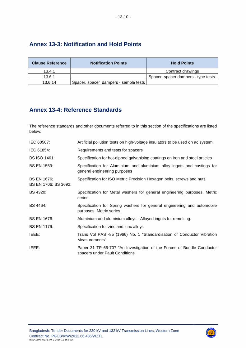
- 13-10 -
Bangladesh: Tender Documents for 230 kV and 132 kV Transmission Lines, Western Zone
Contract No. PGCB/KfW/2012.66.436/WZTLBGD 1800 WZTL vol 2 2016 11 16.docx
Annex 13-3: Notification and Hold Points
Clause Reference Notification Points Hold Points
13.4.1 Contract drawings
13.6.1 Spacer, spacer dampers - type tests.
13.6.14 Spacer, spacer dampers - sample tests
Annex 13-4: Reference Standards
The reference standards and other documents referred to in this section of the specifications are listed
below:
IEC 60507: Artificial pollution tests on high-voltage insulators to be used on ac system.
IEC 61854: Requirements and tests for spacers
BS ISO 1461: Specification for hot-dipped galvanising coatings on iron and steel articles
BS EN 1559: Specification for Aluminium and aluminium alloy ingots and castings for
general engineering purposes
BS EN 1676;
BS EN 1706; BS 3692:
Specification for ISO Metric Precision Hexagon bolts, screws and nuts
BS 4320: Specification for Metal washers for general engineering purposes. Metric
series
BS 4464: Specification for Spring washers for general engineering and automobile
purposes. Metric series
BS EN 1676: Aluminium and aluminium alloys - Alloyed ingots for remelting.
BS EN 1179: Specification for zinc and zinc alloys
IEEE: Trans Vol PAS -85 (1966) No. 1 "Standardisation of Conductor Vibration
Measurements".
IEEE: Paper 31 TP 65-707 "An Investigation of the Forces of Bundle Conductor
spacers under Fault Conditions

- 14-1 -
Bangladesh: Tender Documents for 230 kV and 132 kV Transmission Lines, Western Zone
Contract No. PGCB/KfW/2012.66.436/WZTLBGD 1800 WZTL vol 2 2016 11 16.docx
14. Optical Fibre Cable and Fittings
14.1 Scope
14.1.1 General
This section of the specification covers optical fibre cable suitable for incorporation into the earthwire
(OPGW), associated fittings and non-metallic underground fibre optic cable.
14.1.2 Types and Uses
For details of the specified requirements reference shall be made to Annexes 14-1 to 14-3.
14.2 Design
14.2.1 Reliability
The overall system design of the fibre optic system shall meet the following minimum requirements:
a. Single failure or degradation in any optical fibre not more than one per year averaged over five
years;
b. Failures or degradations affecting more than one optical fibre, not more than one in ten years;
c. Increase in optical system transmission attenuation due to accumulated ageing and other ef-
fects at the end of five years not more than 0.05 dB/km.
14.2.2 Fibre Optic Earthwire (OPGW)
14.2.2.1. The fibre optic earthwire to be supplied shall be suitable for installation on transmission
lines, and shall be supplied complete with all necessary fittings and optical joint boxes. The earthwire,
fittings and optical joint boxes shall be type approved.
14.2.2.2. The fibre optic earthwire shall comprise an optical sub-unit containing optical fibres, over
which shall be laid aluminium, aluminium alloy or aluminium coated steel strands. Reference should
be made to Section 11 for pertinent details of the overall earthwire.
14.2.2.3. The optical sub-unit shall withstand the temperature rise associated with the specified
lightning fault current flowing in the earthwire without damage. The fibre optic earthwire shall be manu-
factured in continuous lengths of not less than 3 km.
14.2.3 Optical Fibres
14.2.3.1. Optical fibres shall be single mode fibre. The fibres shall be coded for ready identification
at each end. Single mode fibres shall conform to ITU-T G652 or to IEC 60793-2-B1 and Annex 14-2.

- 14-2 -
Bangladesh: Tender Documents for 230 kV and 132 kV Transmission Lines, Western Zone
Contract No. PGCB/KfW/2012.66.436/WZTLBGD 1800 WZTL vol 2 2016 11 16.docx
14.2.3.2. The optical fibre coating material shall be mechanically strippable. The optical fibres shall
be capable of being joined by fusion splicing techniques.
14.2.3.3. There shall be no measurable long term or short term optical attenuation change due to
the temperature rise associated with a fault current flowing in an earthwire, or a lightning strike on the
earthwire.
14.2.3.4. The optical fibres shall not be subjected to any critical stresses when the cable is at its
maximum system loading, reference Annex 11-3.
14.2.3.5. After finalisation of the drum lengths, the Contractor/Supplier shall submit calculations for
the expected overall attenuation and dispersion. This is a Hold Point. This will be compared with the
actual values measured after a completion of the installation.
14.2.4 OPGW Fittings
14.2.4.1. The fibre optic earthwire shall be used with approved conductor fittings in accordance
with sections 10 and 12 of the specifications. The application of these fittings shall not damage the
earthwire or the fibres, either mechanically or optically.
14.2.4.2. At each support, a bypass device shall be provided to guide the cable around the earth-
wire fittings associated with the support.
14.2.4.3. Earthwire bonds similar to those specified in Section 10 of the specification shall be pro-
vided.
14.2.4.4. The cable run from the earthwire to the splice enclosure shall be secured to the support
and suitable protection shall be provided to prevent damage from shotgun attack or other accidental
means.
14.2.5 Optical Joint Boxes
14.2.5.1. Optical joint boxes shall be provided to protect the splice joints of optical fibres, either
when individual lengths of fibre optic OPGW, are jointed, or between the fibre optic earthwire and the
underground fibre optic cable. The optical joint boxes shall protect the splice joint from both mechani-
cal and environmental damage.
14.2.5.2. The optical joint boxes shall preferably be of hood/dome type with single end plate in bot-
tom and shall be fitted to the support immediately above the anti-climbing device.
14.2.5.3. The joint boxes shall consist of an external steel or die cast aluminium housing and pro-
vide protection to IEC 60529 IP447, and an internal die cast aluminium or high impact plastic ABS box
to IEC 60529 IP54.
14.2.5.4. The external housing shall be designed so that rain water is directed away from the door,
and there shall be no water ingress when the door is opened.
14.2.5.5. The door of the box shall be fitted with captive hinges and shall be fastened shut by
screw fixings. A hasp shall be provided on the door capable of taking a 10mm padlock.

- 14-3 -
Bangladesh: Tender Documents for 230 kV and 132 kV Transmission Lines, Western Zone
Contract No. PGCB/KfW/2012.66.436/WZTLBGD 1800 WZTL vol 2 2016 11 16.docx
14.2.5.6. The bottom of the box shall be fitted with two gland plates, each gland plate shall have
two entry points. The gland plates shall be interchangeable, one style shall be used for fibre optic
earthwire, the other for underground fibre optic cable. The joint boxes shall be supplied complete with
all fittings to secure and seal the cable in the gland plates or blank the unused spigots. Cable cleats to
secure the fibre optic OPGW or underground cable shall be fitted inside the box. The cleats shall not
have a detrimental effect on the performance of the optical fibres when tightened to the recommended
torque.
14.2.5.7. The top and bottom of the joint box shall be vented, and the vents provided with vermin
shields.
14.2.5.8. An M12 earthing boss complete with an M12 galvanised nut and lock washers shall be
provided on the outside of the box.
14.2.5.9. The interior box shall be mounted on brackets inside the external housing and shall be
capable of easy removal, complete with the optical fibre tails. The seal around the box shall be capa-
ble of withstanding specified temperatures.
14.2.5.10. The box shall be supplied complete with internal splice cassettes to accommodate the
required number of splices. Glands shall be fitted to accommodate either the fibre optic OPGW, or un-
derground fibre optic cable.
14.2.6 Fixing Clamps
A bolted clamping system shall be used to attach the OPGW to the inside of the support without drill-
ing or modifications to the support steelwork. The clamping system shall be capable of use with galva-
nised steel angle sections varying between 40 and 200 mm wide and accommodating either single,
double or multiple lengths of OPGW.
The attachment clamps shall be capable of being attached and detached from the support, without af-
fecting the OPGW.
14.2.7 Non-Metallic Underground Fibre Optic Cable
The fibre optic cable shall be circular in cross section and shall be designed so that any cable strain is
not directly imported on the optical fibres. The cables shall not include any metallic components, to
prevent high induced voltages when used in switching or substation compounds.
Optical fibres shall be in accordance with chapter 14.2.5 and shall match the OPGW, fibres in type
and colour.
- 14-4 -
Bangladesh: Tender Documents for 230 kV and 132 kV Transmission Lines, Western Zone
Contract No. PGCB/KfW/2012.66.436/WZTLBGD 1800 WZTL vol 2 2016 11 16.docx
14.3 Materials
14.3.1 Fibre Optic Earthwire
External aluminium, aluminium alloy or aluminium coated steel strands shall be in accordance with the
requirements of Section 11 of the specification. OPGW of dissimilar materials such as stainless steel
tube with aluminium-clad steel wire strands are not allowed.
14.3.2 Optical Joint Boxes
Optical joint boxes shall be made from either a suitable grade of aluminium alloy complying with the
requirement of BS EN 1559, 1676, 1706 and/or BS EN 1676, or steel complying with requirements of
BS 3100.
14.3.3 Fixing Clamps
Fixing clamps shall be made from a suitable grade of aluminium alloy comprising with the require-
ments of BS EN 1559, 1676, 1706 and/or BS EN 1676. Bolt quality shall be grade 4.6 according to
ISO 898-1. Bolts and nuts shall be ISO Metric Black Hexagon to BS 4190, and shall unless otherwise
specified be threaded ISO Metric Coarse Pitch to BS 3643: Part 2, Tolerance Class 7h/8 g.
14.4 Workmanship
14.4.1 Contract Drawings
Contract drawings for fixing clamps and optical joint boxes shall in addition to the dimension show ma-
terial types and grades, protective treatment and any other pertinent information. Design drawings
shall be submitted to the Employer for approval. This is a Hold Point.
14.5 Protective Treatment
14.5.1 Fibre Optic Earthwire
Where two layers of wire strands are provided over the optical sub-unit, the external surface of the op-
tical sub-unit and the inner strand layer shall be greased, using an approved conductor grease (Ref.
Section 11 of the Specification).
14.5.2 Ingress of Moisture
The cable shall be capped before shipment to prevent the ingress of water.

- 14-5 -
Bangladesh: Tender Documents for 230 kV and 132 kV Transmission Lines, Western Zone
Contract No. PGCB/KfW/2012.66.436/WZTLBGD 1800 WZTL vol 2 2016 11 16.docx
14.5.3 Optical Joint Boxes
Optical joint boxes (steel exterior housings) shall be hot dipped galvanised after manufacture to meet
the requirements of BS ISO 1461. The boxes shall be sufficiently rigid so that there is no distortion of
either the box or its door after galvanising.
14.6 Installation
14.6.1 General
14.6.1.1 The supplier of the OPGW will be responsible for the supervision of installation by the
Contractor, to ensure that overall system reliability requirements are met. To ensure that this is under-
taken, the supplier will provide the services of a suitably qualified/experienced installation supervisor,
who shall supervise the installation of the Works and shall advise the Engineer and the Contractor in
matters of methods procedures and precautions to be followed and will be responsible for all matters
pertaining to the quality of the installation. The supplier's installation supervisor shall make at least four
visits of 2 (two) weeks each during progress of OPGW installation work for the purpose.
14.6.1.2 The Contractor shall provide the Employer with a method statement giving sequential de-
tails of the stripping procedure and the optical fibre jointing (splicing) procedure. The method state-
ment shall take full cognisance of the manufacturer's installation instructions.
14.6.1.3 The method statement shall be submitted to the Employer for acceptance the requisite
period prior to stringing or optical fibre jointing commences. This a Hold Point.
14.6.2 Workmanship
The Contractor shall ensure that the fibre optic cables are not strained or damaged either mechanical-
ly or optically during stringing and/or jointing. If necessary the Contractor shall demonstrate the suita-
bility of his proposed method, including the choice of running blocks prior to the commencement of
stringing operations.
14.6.3 Optical Fibre Joints
Optical fibre joints either in the OPGW, or between the OPGW, and the non-metallic underground fibre
optic able shall be housed in optical joint boxes. The joint boxes shall be located immediately above
the anti-climbing device for convenient access by technical personnel. All joint boxes shall be earthed
to the support steelwork using approved multi-wire/multi-strand flexible aluminium earthing bonds.

- 14-6 -
Bangladesh: Tender Documents for 230 kV and 132 kV Transmission Lines, Western Zone
Contract No. PGCB/KfW/2012.66.436/WZTLBGD 1800 WZTL vol 2 2016 11 16.docx
14.7 Quality Control
14.7.1 General
Type, sample and routine tests shall be undertaken on OPGW, their associated fittings, non-metallic
underground fibre optic cable and the optical fibres in accordance with the requirements of this speci-
fication, ITU-T G652, IEC 60793 and IEC 60794 as appropriate. Contract drawings previously submit-
ted to the Employer shall be available at the time of testing.
The Contractor/Supplier shall give the Employer the requisite period of notice prior to undertaking the
tests, and shall submit to the Employer a test programme and procedures for approval. This is a Hold
Point.
14.7.2 OPGW
14.7.2.1 Type Test
a) Stress-Strain
A sample of OPGW not less than 10m length, complete with the proposed end fittings shall be subject
to a stress-strain test. The test shall be undertaken in accordance with IEC 61089 Annex B and the
measuring techniques in accordance with IEC 60794-1-El. There shall be no visual change to the
OPGW strands after the test and that the fibre strain must be less than 0.05% at 85% of the UTS of
the cable.
b) Tensile Performance
The test shall be undertaken in accordance with the load conditions specified in IEC 61089 Annex B
and the measuring techniques in accordance with IEC 60794-1 El. There shall be no permanent
change in the fibre attenuation at the specified wavelength after the test, while the change in attenua-
tion during the test shall be less than 0.05db/km from zero load to 85% of the UTS of the cable.
c) Crush and Impact
The tests shall be undertaken in accordance with the recommendations of IEC 60794 - 1 - E3 and
IEC-60794 - 1 - E4.
The crush test shall be undertaken by applying a 10kN load for 1min to the OPGW via two 50 x 50 mm
flat plates. There shall be no measurable permanent change in the fibre attenuation at the specified
wavelength, while any temporary change in attenuation shall be less than 0.1db.
The impact test shall be undertaken by dropping a 4kg weight from a height of 150mm onto the end of
a 20mm diameter steel mandrel placed on the OPGW. After 20 repeated applications, there shall be
no measurable change in fibre attenuation at the specified wavelength, while any temporary change in
attenuation shall be less than 0.1 db.
d) Temperature Cycling
The optical performance under temperature cycling shall be tested in accordance with IEC 60794-1-F1
with TA and TB as specified in Annex 14-1 and the duration of 4 hours. The test should be undertaken
twice.
e) Water Ingress
The optical sub-unit shall be tested for water ingress in accordance with IEC 60794-1-F5.

- 14-7 -
Bangladesh: Tender Documents for 230 kV and 132 kV Transmission Lines, Western Zone
Contract No. PGCB/KfW/2012.66.436/WZTLBGD 1800 WZTL vol 2 2016 11 16.docx
f) Fault Current
A sample of OPGW not less than 2m in length shall be subject to a fault current pulse. The fault cur-
rent pulse specified in Annex 14-1 shall be supplied in less than 1s after the conductor has been
raised to the specified initial temperature. During the test the temperature of the optical sub-unit shall
be measured, the temperature immediately after the current pulse shall be less than the specified
temperatures. The test shall be performed twice with an interval of 30 min between tests. After the
second impulse the OPGW shall be dismantled and the optical cable examined throughout its length
for any signs of deterioration.
g) Lightning Strike
The Contractor shall submit his proposals to the Employer to demonstrate the effectiveness of the
OPGW to withstand the effects of a lightning strike. The test shall consider both an initial stroke and a
power follow through. The initial peak current shall be as specified in Annex 14-1. The test shall be
carried out on a sample of OPGW not less than 2m long. The acceptance criteria shall be that calcu-
lated residual strength of earthwire is not less than 90% of the original stated ultimate tensile strength.
Any damaged strands shall be assumed to be broken.
14.7.2.2 Routine Test
14.7.2.2.1. OPGW on all drums shall be tested for mechanical Tests including measurement of di-
mensions of steel and aluminium (Al) wires and overall diameter of OPGW, measurements of thick-
ness of Al on ACS wires, twist test of steel & Al wires, torsion test of steel wires, checking of lay length
& lay ratio of layers, checking of lay directions, breaking load test of steel and Al wires and DC re-
sistance measurement of Al and ACS wires at the factory by the manufacturer as routine tests.
14.7.2.2.2. In addition, attenuation shall be measured on each fibre of all OPGW with OTDR at the
factory by the manufacturer as routine test.
14.7.2.2.3. The test results shall be available with the manufacturer and shall be submitted to the
Employer, if requested.
14.7.2.3 Sample Test
Samples taken on random sampling basis from the OPGW drums ready for shipment against each
batch shall be tested for mechanical tests including measurement of dimensions of steel and alumini-
um (Al) wires and overall diameter of OPGW, measurements of thickness of Al on ACS wires, twist
test of steel & Al wires, torsion test of steel wires, checking of lay length & lay ratio of layers, checking
of lay directions, breaking load test of steel and Al wires and DC resistance measurement of Al and
ACS wires at the factory by the manufacturer which shall be witnessed by the Employer's representa-
tive.
In addition, attenuation shall also be measured on each fibre of above mentioned sample drums of
OPGW with OTDR.
14.7.3 Optical Fibres
Optical fibres shall be tested in accordance with the requirements of ITU-T G652 and IEC 60793 as
appropriate.

- 14-8 -
Bangladesh: Tender Documents for 230 kV and 132 kV Transmission Lines, Western Zone
Contract No. PGCB/KfW/2012.66.436/WZTLBGD 1800 WZTL vol 2 2016 11 16.docx
14.7.4 Optical Joint Boxes
Optical joint boxes shall be visually inspected to ensure they meet the specified requirements. If the
external housing or its door shows any signs of distortion or any galvanizing damage then the box
shall be rejected. Details of the inspection shall be recorded and shall be made available to the Engi-
neer upon request.
14.7.5 Non-Metallic Underground Fibre Optic Cable
Non-metallic underground fibre optic cable and the optical fibres shall be tested in accordance with the
requirements of ITU-T G652, IEC 60793 and IEC 60794 as appropriate.
14.7.6 Fibre Optic Cables
All fibre optic cables shall be tested prior to despatch using an OTDR on each fibre.
14.7.7 Test Certificates
Test records, covering Type and Sample tests shall be made available to the Employer.
14.7.8 Certificates of Conformity
When requested copies of the following certificates/records shall also be forwarded:
a. Optical joint boxes visual inspection records;
b. Routine test records;
c. The records of the OTDR test results.
14.7.9 Installation
14.7.9.1. The following tests shall be undertaken by the Contractor:
a. Prior to installation the fibre optic cable shall be tested with an OTDR on each fibre to ensure
that no physical damage has occurred to the fibre during delivery and shall be compared with
the results prior to despatch;
b. After installation the above test shall be repeated to ensure that no damage has occurred to the
fibre during installation;
c. An end-to-end attenuation measurement shall be taken in each direction on each fibre using an
optical source and optical power meter.
14.7.9.2. The overall attenuation of the installed cable shall not exceed that calculated using the at-
tenuation and splice loss values specified in Annex 14-2.
14.7.9.3. The Contractor shall give the Engineer the requisite period of notice prior to commencing
the tests. This is a Notification Point. Details of the test results shall be submitted to the Employer.

- 14-9 -
Bangladesh: Tender Documents for 230 kV and 132 kV Transmission Lines, Western Zone
Contract No. PGCB/KfW/2012.66.436/WZTLBGD 1800 WZTL vol 2 2016 11 16.docx
14.7.9.4. The supplier of the OPGW is requested to co-operate with the Fibre Optic Terminal
Equipment Supplier (if this is under a separate contract) and shall supply all technical data requested.
14.8 Test Equipment
Reference should be made to Annex 14-3 for details of the test equipment required.
14.9 Maintenance Equipment and Tools
Reference shall be made in the price schedule, mandatory spare part and tools.

- 14-10 -
Bangladesh: Tender Documents for 230 kV and 132 kV Transmission Lines, Western Zone
Contract No. PGCB/KfW/2012.66.436/WZTLBGD 1800 WZTL vol 2 2016 11 16.docx
Annex 14-1: OPGW Design Requirements - 230kV, 132kV
230 kV 132 kV
Number of fibres 48 24
Fault current (1 second) (kA) 5 5
Initial temperature (°C) 40 40
Leading edge (µs) 1.2 1.2
Lightning initial peak current (kA) 100 100
Tail (µs) 50 50
Power follow through (Coulomb) 200 200
Temperature cycling test TA (°C) 5 5
Temperature cycling test TB (°C) 40 40
Annex 14-2: Single Mode Optical Fibre Cable Requirements
Coating diameter μm 250 ± 15
Cladding diameter μm 125 ± 3
Cladding non-circularity % ≤2
Mode field diameter μm 9 ± 1
Mode field concentricity error μm ≤1
Cut off wave length nm ≤1,270
Attenuation at (maximum average) 1285 nm 1330 dB/km ≤0.40
Attenuation at (maximum average) 1550 nm dB/km ≤0.25
Zero dispersion wave length nm ≤1,321
Chromatic dispersion at 1285 nm 1330 ps/(km-nm) ≤3.50
Chromatic dispersion at 1550 nm ps/(km-nm) ≤20
Individual splice loss dB ≤0.10
Mean splice loss dB ≤0.06
Annex 14-3: Test Equipment
OTDR
Annex 14-4: Engineering Documents to be Submitted by Contractor
Clause Reference Document Description Comment

- 14-11 -
Bangladesh: Tender Documents for 230 kV and 132 kV Transmission Lines, Western Zone
Contract No. PGCB/KfW/2012.66.436/WZTLBGD 1800 WZTL vol 2 2016 11 16.docx
Clause Reference Document Description Comment
14.2.3 Expected overall attenuation and dispersion
14.4.1 Optical Joint Boxes - Contract drawings
Fixing clamps - contract drawings
14.6.1 Installation instructions
14.6.1 Method statement
14.7.1 OPGW fittings, Non-metallic underground fibre optic
cable and optical fibres - type test certificates
14.7.2 Type test programme
14.7.2 OPGW - fatigue life Documentary evidence
14.7.2 OPGW - lightning strike Test proposals
14.7.2 OPGW - routine tests Test proposals
14.7.4 Optical joint boxes - visual inspection test records
14.7.9 OPGW fittings and optical fibres - type test records
14.7.9 OPGW fittings & optical fibres- routine test records
14.7.8 Certificate of conformity
14.7.9 Installation test records
Annex 14-5: Notification and Hold Points
Clause Reference Notification Point Hold Point
14.2.3 Optical Fibres
14.2.6 Fixing clamps
14.4.1 Contract drawings - method statement
14.6.1 Installation - Type test programme
14.7.1 Quality Control - Lightning strike - test proposals
14.7.9 Installation tests
Annex 14-6: Reference Standards
The reference standards and other documents referred to in this section of the specifications are listed
below:
IEC 60529: Classification of decrees of protection provided by enclosures
IEC 61089: Round wire concentric lay overhead electrical stranded conductors
IEC 60793- 1: Optical Fibres Part 1: Generic Specification
IEC 60793-2: Optical Fibres Part 2: Product Specification
IEC 60794-1: Optical Fibre Cable Part 1: Generic Specification

- 14-12 -
Bangladesh: Tender Documents for 230 kV and 132 kV Transmission Lines, Western Zone
Contract No. PGCB/KfW/2012.66.436/WZTLBGD 1800 WZTL vol 2 2016 11 16.docx
IEC 60794-2: Optical Fibre Cable Part 2: Product Specification
BS ISO 1461: Specification for hot dip galvanised coatings on iron and steel articles
BS EN 1559: Specification for Aluminium and aluminium alloy ingots and castings for
general engineering purposes
BS EN 1676;
BS EN 1706; BS 3100:
Specification for steel castings for general engineering purposes
BS 3643: Ingot zinc
BS 4190: Specification for ISO Metric hexagon bolts, screws and nuts
BS EN 1676: Aluminium and aluminium alloys - Alloyed ingots for remelting
BS EN 10025: Specification for hot rolled products of non-alloying structural steels and
their technical delivery requirements.
ISO 898-1: Mechanical properties of fasteners made of carbon steel and alloy steel
ITU-T G652: Characteristics of single mode optical fibre cable.

- 15-1 -
Bangladesh: Tender Documents for 230 kV and 132 kV Transmission Lines, Western Zone
Contract No. PGCB/KfW/2012.66.436/WZTLBGD 1800 WZTL vol 2 2016 11 16.docx
15. Aircraft Navigation (Obstruction Aids)
15.1 Scope
15.1.1 Types and Uses
The type and arrangement of all aircraft navigation (obstruction aids) i.e. aircraft warning lights (solar
or LV powered), solar arrays, batteries and aircraft warning spheres shall be approved by the Employ-
er.
Reference is made to Annex 15-1 for the detailed specific requirements.
15.2 Design
15.2.1 General
All aircraft navigation (obstruction aids) shall be so designed as to:
(a) Withstand the mechanical loads relevant to the installation-service-maintenance conditions and
environmental effects;
(b) Minimize the number of parts and the possibility of incorrect assembly and installation;
(c) Ensure that individual components are secured against becoming loose in service; all threaded
fasteners shall be locked;
(d) Utilize materials which have sufficient strength, ductility and environmental resistance to with-
stand the static dynamic loading;
(e) Avoid damaging the earthwire under all service conditions;
(f) Comply with the requirements of ICAO Aerodromes Annex 14 Volume 1 Aerodrome Design and
Operation and Aerodrome Design Manual Part 4 unless stated to the contrary.
15.2.2 Obstruction Lights (Solar Powered)
15.2.2.1. The complete solar powered obstruction light system i.e. obstruction lights, photovoltaic
cells, storage batteries and control equipment, shall be designed to ensure maximum unattended op-
eration with minimal maintenance, i.e. maximum once per year.
15.2.2.2. The obstruction lights shall consist of one main and one stand-by medium intensity omni-
directional red lamps in compliance with Annex 15-1.
15.2.2.3. The light shall be equipped with LED clustered lamps with medium intensity and a rated
life of at least 20,000 hours.
15.2.2.4. The light shall be designed to allow it to be directly installed on any vertical or horizontal
surface on the peak of the tower. In case the power adapter cannot be installed at the lamp locations,
an extension cable assembly with lamp holder shall be provided.

- 15-2 -
Bangladesh: Tender Documents for 230 kV and 132 kV Transmission Lines, Western Zone
Contract No. PGCB/KfW/2012.66.436/WZTLBGD 1800 WZTL vol 2 2016 11 16.docx
15.2.2.5. The operation of the lights during darkness or poor visibility shall be controlled by a pho-
toelectric switch. The levels of illuminance falling on a vertical surface for activating the lights shall be
agreed with the Engineer.
15.2.3 Obstruction Lights (LV powered)
15.2.3.1. Obstruction lights shall consist of one main and one standby low intensity omnidirectional
red lamps in compliance with Annex 15-1.
15.2.3.2. The luminous intensity shall be medium and have the longest possible rated life, which
should not be less than 10,000 hours.
15.2.3.3. The light shall be designed to allow it to be directly installed on any vertical or horizontal
surface on the tower. The operation of the light during darkness or poor visibility shall be controlled by
a photo-electric switch. The level of illuminance falling on a vertical surface for activating the lights
shall be agreed with the Engineer.
15.2.3.4. At the base of the tower immediately above the A.C.D. level a termination box shall be
provided complete with isolator and other control gear as necessary.
15.2.3.5. The termination box shall be manufactured from either steel or die cast aluminium to pro-
vide protection to IEC 60529 IP 55.
15.2.4 Photo-Voltaic Cells (Solar Array)
15.2.4.1. The photo-voltaic cells in conjunction with the storage batteries shall be designed to have
the maximum system reliability and battery life. Solar panels shall not be designed to provide maxi-
mum power during, periods of peak solar radiation, but to provide power at an essentially constant
rate over the annual solar cycle. The minimum charge state shall provide adequate reserve for weath-
er anomalies which may comprise up to one month of continuous heavy cloud cover, whilst the maxi-
mum charge state achieved during favourable conditions shall not exceed the rated battery capacity to
prevent the possibility of overcharging the battery causing electrolyte evaporation.
15.2.4.2. For protection of the solar array from reverse currents during darkness, a diode shall be
placed in series with the array.
15.2.4.3. The complete solar panel shall be designed to ensure that the maximum electrical Output
degradation shall not exceed 10 percent over a 10 year period.
15.2.4.4. The photo-voltaic cells shall be redundantly interconnected and provided with integral by-
pass diodes to prevent cell overheating due to localized shading and system continuity in the event of
cell circuit failure.
15.2.4.5. The complete solar panel shall be suitably sealed in an aluminium frame which effectively
isolates the cells from thermal and mechanical shock and-prevents the ingress of moisture.

- 15-3 -
Bangladesh: Tender Documents for 230 kV and 132 kV Transmission Lines, Western Zone
Contract No. PGCB/KfW/2012.66.436/WZTLBGD 1800 WZTL vol 2 2016 11 16.docx
15.2.5 Support Framework
The solar array support framework shall be designed to mount the complete solar panel at the opti-
mum tilt angle, and to resist the imposed wind loading calculated in accordance with Section 8 of this
specification.
15.2.6 Storage Batteries
Vented lead acid electrolyte batteries of an extremely low self-discharging type shall be used in con-
junction with photo-voltaic cells. Catalytic recombinator caps shall be used to reduce water loss to very
low levels. The batteries shall have proven cycling abilities in conjunction with photo-voltaic operation
and shall be designed to provide power during periods of low solar radiation, which shall not be less
than a minimum of 5 days, reserve storage plus specified low solar storage calculated from the opti-
mum storage array, size associated with the location.
A regulator shall be used to protect the battery from overcharging and a low voltage disconnector from
excessive discharge.
The batteries must have a stable voltage characteristic with less than 5 percent variation in nominal
output voltage from fully charged to discharged.
Separate batteries and chargers shall be provided for each light.
15.2.7 Battery Enclosure
A suitably designed battery enclosure shall be provided for housing the batteries and control unit at
the specified work platform level.
The enclosure shall have hinged access panels for ease of battery maintenance, vent holes in the
base and ventilation at the top to provide adequate air through venting of gases from the batteries.
Maximum and minimum electrolyte levels of all battery cells shall be clearly visible.
15.2.8 LV Cables
All LV cables and cabling shall be in accordance with the appropriate British Standards and local
health and safety requirements.
15.2.9 Aircraft Warning Spheres
Aircraft warning spheres shall be a minimum of 600 mm diameter and shall be fitted to the earthwire.
Externally, the spheres shall be coloured red or orange to meet the local environmental conditions and
installed alternatively with white spheres. All component bolts shall be captive and preference shall be
given to use of shear-head clamp tightening bolts. Factory formed helical armour rods shall be fitted to
protect the earthwire at aircraft warning sphere locations.
- 15-4 -
Bangladesh: Tender Documents for 230 kV and 132 kV Transmission Lines, Western Zone
Contract No. PGCB/KfW/2012.66.436/WZTLBGD 1800 WZTL vol 2 2016 11 16.docx
15.2.10 Tower Painting
15.2.10.1. Painting of towers to comply with the requirements of ICAO and local aviation authorities,
shall be undertaken when specified by the Engineer.
15.2.10.2. The paint system shall comprise an etch primer, under and gloss coat which shall be for-
mulated to take into consideration the local environmental conditions. The paint shall not present a
health hazard and shall conform to relevant current health and safety requirements.
15.2.10.3. Reference shall be made as appropriate to BS 5493. Details of the proposed painting
system shall be submitted to the Engineer. This is a Hold Point.
15.2.10.4. For details of the extent of the painting requirements reference should be made to Annex
15-1.
15.2.10.5. In some areas where the tower may be under water during the rainy season, the tower
(All members) shall be painted for navigation with reflecting paint up to 3 m above epoxy coat The
Contractor has to submit the details specification of the reflecting paint and the location nos. of the
towers which shall be painted, to the Employer's engineer for approval before start of the painting.
15.3 Materials
15.3.1. Materials used in the manufacture of aircraft navigation (obstruction aids) shall be of:
(a) Adequate strength for the intended application and service life requirements (including mechan-
ical loads, vibrations, electrical currents and environmental effects) and free from defects which
would affect the performance of the equipment.
(b) Shall not be liable to intergranular or stress corrosion.
(c) The material shall not be adversely affected in the long term by a coating applied for corrosion
protection.
15.3.2. Photovoltaic cells shall comprise matched monocrystalline silicon cells enclosed by a
glass front surface and a rear composite layer to provide the optimum thermal and electrical perfor-
mance.
15.3.3. The glass front surface shall have similar thermal expansion characteristics to the photo-
voltaic cell, shall be resistant to impact and abrasion by wind-blown materials and shall be self-
cleaning under the action of rain.
15.3.4. All mild steel used in the manufacture of the support framework shall comply with the re-
quirements of BS EN 10025 or BS EN 10210. Minimum steel grade shall be S275JR and S275JOH
respectively.
15.3.5. Aluminium or aluminium alloy used in the manufacture of the complete solar panel frame
shall comply with the requirements of BS 1474.
15.3.6. Cast aluminium and aluminium alloy fittings shall be made from aluminium or aluminium
alloy of a suitable grade, complying with the requirements of BS 1490 and/or BS EN 1676.

- 15-5 -
Bangladesh: Tender Documents for 230 kV and 132 kV Transmission Lines, Western Zone
Contract No. PGCB/KfW/2012.66.436/WZTLBGD 1800 WZTL vol 2 2016 11 16.docx
15.3.7. Aircraft warning spheres shall be made from either glass reinforced polyester resin or al-
uminium sheet, having a minimum specified thickness. Aluminium sheet shall comply with the re-
quirements of BS EN 485
15.3.8. Bolts and nuts shall be either ISO Metric Black Hexagon to BS 4190 threaded ISO Metric
Course Pitch to BS 3643: Part 2 Tolerance Class 7H/8g, or ISO Metric Precision Hexagon to BS 3692.
Metal washers shall be either to BS 4320, Form E, Grade 4.6 or 'bright series'. Spring Washers shall
be ISO Metric to BS 4464.
15.3.9. If shear-head type bolts are used they shall be clearly marked so after the correct torque
has been applied, the installed bolt may be clearly identifiable from the ground.
15.3.10. Non-metallic materials shall have good resistance to ageing and shall have adequate re-
sistance to the effects of nitrogen oxide, ozone, ultra-violet radiation and air pollution.
15.3.11. Glass reinforced polyester resin mouldings for aircraft warning spheres shall be in ac-
cordance with BS 4549, Part 1.
15.3.12. All paints used shall be suitable for use with and not adversely affect galvanized steel.
15.4 Workmanship
The dimensions of all aircraft navigation (obstruction aids) equipment shall be shown on the contract
drawings. Contract drawings including cabling layouts shall be submitted to the Engineer. This is a
Hold Point.
All equipment shall be marked to ensure a system of traceability for each component of the equip-
ment. Where practicable, and unless otherwise agreed between the Engineer and the Contractor /
Supplier, equipment shall be clearly and indelibly marked with 6 mm high characters as follows:
(a) Identification of equipment (reference number);
(b) Maker's identification;
(c) Date of manufacture (month and year);
(d) Cast code - if appropriate;
(e) Conductor diameter range - if appropriate;
(f) Fitting bolt installation torque - if appropriate.
15.5 Protective Treatment
All parts of the aircraft navigation (obstruction aids) equipment shall either be inherently resistant to
atmospheric corrosion or suitably protected against corrosion, such as may occur in transit, storage
and service. All ferrous parts which will be exposed to the atmosphere in service shall be protected by
hot- dipped galvanizing to comply with the requirements of BS 729. All manufacturing processes shall
be completed prior to galvanizing.

- 15-6 -
Bangladesh: Tender Documents for 230 kV and 132 kV Transmission Lines, Western Zone
Contract No. PGCB/KfW/2012.66.436/WZTLBGD 1800 WZTL vol 2 2016 11 16.docx
The ingot zinc used for galvanizing shall comply with the requirements of BS 3436. All external
threads shall be cut or rolled before hot-dipped galvanizing. Nuts to be galvanized shall be subse-
quently tapped 0.4 mm oversize and the threads oiled.
15.6 Installation
Aircraft navigation (obstruction aids) shall be installed strictly in accordance with the Supplier's instruc-
tions.
The proposed means of paint application shall take full cognizance of local environmental require-
ments and shall be subject to the approval of the Engineer. This is a Hold Point.
15.7 Quality Control
15.7.1 General
Type, sample and routine tests as appropriate shall be undertaken on both individual items and com-
plete system, e.g. obstruction lights, solar panels, storage batteries etc. in accordance with the re-
quirements of this specification. The test procedure must clearly demonstrate the suitability of the
complete system to meet the environmental and operational conditions specified. The Contractor's
proposals for these tests shall be submitted to the Engineer for approval before manufacture com-
mences. This is a Hold Point.
Contract drawings previously submitted to the Engineer shall be available at the time of testing. The
Contractor/Supplier shall give the Engineer the requisite period of notice prior to undertaking the type
and sample tests, and shall submit to the Engineer for approval a test programme and procedures.
This is a Hold Point.
15.7.2 Galvanising
Tests for galvanised equipment shall be carried out at the works to ensure compliance with the re-
quirements of BS 729. Details of the test results shall be made available to the Engineer upon request.
15.7.3 Test Certificates
15.7.3.1. All metallic materials used in the manufacture of the equipment shall be covered by test
certificates stating their mechanical and chemical properties to prove compliance with requirements of
this specification and BS EN 10210, BS EN 10025, BS EN 485, BS 3 1 00, BS 4190, BS 1474, BS
1470 as appropriate.
15.7.3.2. Bolts and nuts shall be covered by the appropriate test certificate in respect of either BS
4190 or BS 3692. Tests certificates for metallic materials, bolts and nuts and where appropriate non-
metallic materials shall be made available to the Engineer upon request.

- 15-7 -
Bangladesh: Tender Documents for 230 kV and 132 kV Transmission Lines, Western Zone
Contract No. PGCB/KfW/2012.66.436/WZTLBGD 1800 WZTL vol 2 2016 11 16.docx
15.7.3.3. Where type and sample tests are undertaken test certificates covering these tests shall
be made available to the Engineer.
15.7.3.4. Where routine tests are undertaken test certificates covering the tests shall be made
available to the Engineer upon request.
15.7.4 Certificate of Conformity
Prior to despatch the Contractor/Supplier shall forward to the Engineer requisite copies of the com-
pleted Certificate of Conformity. The certificate shall be supported by copies of the appropriate test re-
ports of any type and/or sample tests undertaken.
When requested copies of the following certificates/records shall also be forwarded:
(a) Metallic material test certificates
(b) Bolt and nut test certificates
(c) Non-metallic material test certificates
(d) Galvanizing test records
(e) Routine test records.
15.7.5 Site Tests
Prior to commissioning the Contractor shall submit to the Engineer his proposals for checking/testing
the complete installation. This is a Hold Point. The Contractor shall give the Engineer the requisite
period of notice prior to undertaking the agreed commissioning tests. This is a Notification Point.
15.7.6 Painting
Prior to the commencement of painting the Contractor shall submit to the Engineer his proposals for
checking/testing the routine quality of the Painting. This is a Hold Point.

- 15-8 -
Bangladesh: Tender Documents for 230 kV and 132 kV Transmission Lines, Western Zone
Contract No. PGCB/KfW/2012.66.436/WZTLBGD 1800 WZTL vol 2 2016 11 16.docx
Annex 15-1: Aircraft Navigation (Obstruction Aids)
Tower painting as per ICAO requirements
Tower painting as per local requirements
Obstruction lights
L.V. powered & supply voltage
Obstruction Light type
V
Yes
-
Solar powered
-
Medium intensity, type C
Solar powered:
Number and position of lights per support As per ICAO
Height and position of work platform
Height and position of solar array
Top crossarm
Earthwire
Diameter of aircraft warning spheres
Spacing of aircraft warning spheres
mm
m
600
30 between adjacent spheres on opposite
earthwires
Tower Painting
All river crossings towers and towers of which total height above GL exceeds 45 m are to be painted,
to conform to the requirements of ICAO.
Annex 15-2: Engineering Documents to be Submitted by Contractor
Clause Reference Document Description Comments
15.2.10 Tower painting - painting system
15.4.1 Obstruction aids - contract drawing
15.6.2 Painting - method statement
15.7.1 Test proposals - type, sample, routine
15.7.2 Galvanizing test results If requested
15.7.3 Metallic material test certificates If requested
15.7.3 Bolt and nuts test certificates If requested
15.7.3 Non-metallic material test certificates If requested
15.7.3 Type test records
15.7.3 Sample test records
15.7.3 Routine test records If requested
15.7.4 Certificate of conformity
15.7.5 Commissioning test proposals
15.7.6 Painting - routine test procedure

- 15-9 -
Bangladesh: Tender Documents for 230 kV and 132 kV Transmission Lines, Western Zone
Contract No. PGCB/KfW/2012.66.436/WZTLBGD 1800 WZTL vol 2 2016 11 16.docx
Annex 15-3: Notification and Hold Points
Clause Reference Notification Points Hold Points
15.2.10 Tower painting system
15.4.1 Contract drawings
15.6.2 Painting - method statement
15.7.1 Test proposals
15.7.1 Type tests
15.7.5 Commissioning tests Test proposals
15.7.6 Painting - routine test proposals
Annex 15-4: Reference Standards
The reference standards and other documents referred to in this specification are listed below:
IEC 60529: Classification of degrees of protection provided by enclosures.
BS 729: Specification for hot-dipped galvanising coating on iron and steel articles.
BS 1474: Specification for wrought aluminium and aluminium alloys for general engineering
purposes bars, extruded round tubes and sections.
BS 1490: Aluminium and aluminium alloy ingots and castings for general engineering pur-
poses.
BS 3463: Specification for ingot zinc.
BS 3643: ISO Metric threads. Part 2: Limits and tolerances for course pitch series threads.
BS 3692: Specification for ISO Metric Precision hexagon bolts, screws and nuts.
BS 4190: Specification for ISO Metric hexagon bolts, screws and nuts.
BS 4320: Specification for metal washers for general engineering purposes Metric series.
BS 4549: Guide to quality control requirements for reinforced plastic moulding.
Part 1: Polyester resin mouldings reinforced with chopped strand mat or randomly depos-
ited glass fibre.
BS 4464: Specification for Spring washers for general engineering and automobile pur-
poses. Metric Series.
BS 5493: Protective coatings of iron and steel structures.
BS EN 485: Aluminium and aluminium alloys sheet, strip and plate.
BS EN 1676: Aluminium and aluminium alloys - Alloyed ingots for remelting,
BS EN 10025: Specification for hot rolled products of non-alloy structural steels and their tech-
nical delivery requirements.
BS EN 10210: Hot finished structural hollow sections of non-alloy and fine grain structural steels.

- 16-1 -
Bangladesh: Tender Documents for 230 kV and 132 kV Transmission Lines, Western Zone
Contract No. PGCB/KfW/2012.66.436/WZTLBGD 1800 WZTL vol 2 2016 11 16.docx
16. Miscellaneous
16.1 Tools and Appliances
16.1.1Each tool or appliance shall be clearly marked with its size and/or purpose and is not to be used
for erection purposes by the Contractor.
16.1.2The tools and appliances with the appropriate boxes are to be handed over to the Employer at
the Employer's stores depot at the time of arrival at site.
16.1.3The Contractor shall, where required, by the Engineer, provide test certificates and die-stamp or
indelible mark on each piece of equipment in an approved manner.
16.1.4For details of the tools and appliances to be supplied reference should be made to Annex 16-1.

- 16-2 -
Bangladesh: Tender Documents for 230 kV and 132 kV Transmission Lines, Western Zone
Contract No. PGCB/KfW/2012.66.436/WZTLBGD 1800 WZTL vol 2 2016 11 16.docx
Annex 16-1: Tools & Appliances
(a) Sets of temporary earthing equipment shall consist of one, telescopic, Fibre glass rod 3m total
length, complete with a screwing head together with 6 PVC covered 8m lengths of 150mm2
pure aluminium conductor. Each length of conductor shall be equipped with an earth end clamp
which shall have a hardened steel threaded point capable of piercing a galvanised or corrod-
ed steel surface to provide a good earth connection. In addition an alloy line end clamp shall
be provided which shall be spring loaded and capable of being further tightened around a con-
ductor of up to 32.4mm diameter, to provide a good electrical connection. The line end clamp
and the screwing head of the pole shall be such that the latter is capable of holding, fixing and
tightening the end clamp onto the conductor when attached to the temporary earth lead.
The leads are expected to withstand a fault current of 2.5kA for 10s.
(b) Elcometer for measuring galvanisation thickness.

- 17-1 -
Bangladesh: Tender Documents for 230 kV and 132 kV Transmission Lines, Western Zone
Contract No. PGCB/KfW/2012.66.436/WZTLBGD 1800 WZTL vol 2 2016 11 16.docx
17. Packing, Protection and Despatch Marking
17.1 General
17.1.1. The following minimum packing methods shall be adopted for suppliers external to the
country of the transmission line installation, unless otherwise specified.
17.1.2. The Supplier shall be entirely responsible for ensuring that the packing is suitable for
transit and storage and will be held responsible for any shortages or damage during transit.
17.1.3. Wherever possible, the Supplier shall utilize shipping by container vessels in the contain-
ers of the correct type for the item being shipped to reduce the likelihood of damage to the items. If
containerization is not possible the requirements of the following clauses shall be applicable.
17.1.4. All materials shall be carefully packed in a manner suitable for transport to and storage
under the climatic conditions present. Items packed in cases or crates shall be so secured that they
are not free to move, and cannot work loose in transit.
17.1.5. Wood wool is to be avoided as a packaging material as far as possible.
17.1.6. Waterproof paper and felt lining are to overlap at the seams by at least 12mm, and the
seams secured together in an approved manner, but the enclosure is to be provided with vermin proof
screened openings to permit ventilation.
17.1.7. A packing note in a weatherproof plastic envelope is to be securely attached to the right
hand lower corner of one side of all cases or crates. A copy of the packing list shall also be included
inside.
17.1.8. All packing cases or crates shall be marked on the outside to show the correct way up
and where relevant, where the weight is bearing and the correct positions for slings.
17.1.9. Shipping mark, numbers and symbols will be provided by the Employer. These marks
shall be applied to conductor drums and cases either by the use of a waterproof stencil, flo-pen or any
other permanent method. The use of tie-on tags is not permitted. Cases shall be marked on two oppo-
site sides.
All marks shall be clearly legible at the time of dispatch.

- 17-2 -
Bangladesh: Tender Documents for 230 kV and 132 kV Transmission Lines, Western Zone
Contract No. PGCB/KfW/2012.66.436/WZTLBGD 1800 WZTL vol 2 2016 11 16.docx
17.2 Lattice Tower and Associated Steelwork
(a) Main Legs Steel Poles, Heavy Sections
As loose items, or as below.
(b) Angle Bracings and Large Plates
Bundled in packages of less than 5t and strap-bonded as follows:
Galvanized -tensional steel stripping, either:
i) Tension strapping 32mm x 0.8mm, minimum of two bands and at maximum centres of 2m; or
ii) Tension strapping 19mm x 0.8mm, minimum of three bands and at maximum centres of 1.25m.
Whichever method i) or ii) is adopted, bundles shall also have a layer of either hessian or poly-
thene between the strap-bands and the galvanized steelwork. One end of the bundle shall also be
wired in such a way as to prevent the removal of any single piece.
(c) Plates, Small Items
These shall be cased (maximum net mass 500kg).
Cases shall be of sturdy construction, made from new 25mm thick timber and constructed with annular
(rag) nails. They shall have packing pieces on the underside to enable the use of fork- lift trucks.
(d) Bolts
Shall be double bagged and cased as above. A contents list shall be included in each bag. (Cases
used both (c) and (d) shall be stored in dry areas both before and after packing.
Where required, materials shall be colour flashed to aid recognition.
17.3 Containerisation
Where materials shipped by the use of containers, a reduced level of packing, is acceptable as fol-
lows:
(a) Strap-band centres may be increased to 3m for 32mm x 0.8mm bands and 2.5m for 19mm x
0.8mm bands.
(b) The use of wire through bundle ends is not required.
(c) Cases may be 20mm thick timber.

- 17-3 -
Bangladesh: Tender Documents for 230 kV and 132 kV Transmission Lines, Western Zone
Contract No. PGCB/KfW/2012.66.436/WZTLBGD 1800 WZTL vol 2 2016 11 16.docx
17.4 Conductor
17.4.1. Conductors shall be supplied on drums of sufficient sturdiness to withstand overseas
shipment, and the drums shall be securely battened to prevent damage to the conductor.
17.4.2. All wooden components shall be manufactured from sound defect-free seasoned soft-
wood and suitable for prolonged storage without deterioration. Wood shall be either planed or finely
sawn to facilitate accuracy in assembly. The thickness of each ply or component part shall be of rea-
sonable uniformity.
17.4.3. The flanges of drums shall be constructed from two ply of wood laminated in such a
manner to be cross-grain to each other. The boards shall be close butted to provide maximum sup-
port. Fastenings of the flanges shall be with suitable bright nails with the head countersunk on the in-
side flange. A flange conductor hole of sufficient diameter for the free passage of the conductor shall
be cut in one flange. The exposed end of the conductor shall be protected by a suitable sheet metal
plate.
17.4.4. Drainage holes shall be provided through each flange as close as possible to the under-
side of the barrel lagging. The inner checks of the drum shall be painted with an aluminium flake or bi-
tumen based paint.
17.4.5. The spindle hole shall be round and cut through the centre of the centre board of each
flange ply. The spindle holes, of not less than 80mm diameters, shall be reinforced by a 6mm mild
steel plate bolted to each flange.
17.4.6. The drum barrel shall be of the segmented type, with supports and cross struts, with a di-
ameter not less than 30 times the conductor diameter. The barrel lagging shall be closely butted and
shall provide a smooth external finish to the conductor. The barrel and flanges shall be securely
clamped together by not less than six M20 bolts.
17.4.7. The inner end of the conductor shall be brought through the drum flange and secured by
staples. The outer end shall also be secured to the inner face of the flange in a similar manner painted
with aluminium flake paint.
17.4.8. The outer layer of the conductor on the drum shall be covered by either a layer of sheet
plastic or waxed paper secured immediately under the circumferential battens so that it is not in con-
tact with the conductor.
17.4.9. Circumferential battens shall enclose the conductor space completely. They shall fit flush
with the outer flanges and shall be securely fixed.
17.4.10. Drums shall be provided with a secure waterproof label displaying the maker's name,
type, size and length of conductor on the drum. Drum serial number shall be either chiselled into one
drum cheek or impressed onto a secure metallic label. Drums shall be painted on all outer surfaces in
finishing colours to the option of the manufacturer.
17.4.11. Drums shall display an arrow and the words "Roll This Way" on each cheek to show the
correct direction of rolling.
- 17-4 -
Bangladesh: Tender Documents for 230 kV and 132 kV Transmission Lines, Western Zone
Contract No. PGCB/KfW/2012.66.436/WZTLBGD 1800 WZTL vol 2 2016 11 16.docx
17.4.12. Steel conductor drums shall be used for any spare conductor supplied and shall comply
with the requirements of the American Aluminium Association Standards or other equivalent National
Standards.
17.5 Insulators
17.5.1Insulators shall be crated, each crate shall contain insulators units of the same type. Crates
shall be either hexagonal or rectangular cross section.
17.5.2Crates shall be wooden and close boarded, manufactured from sound seasoned softwood a
minimum of 20mm thick. They shall be tensioned strapped at not less than three positions along their
length. All crates shall be marked with the batch number and insulator code number.
17.5.3Special attention shall be paid to ensure that all insulators are complete with their security clip.
17.6 Insulator, Conductor and Ancillary Fittings
Insulator, conductor and ancillary fittings shall be cased as per chapter 17.2(c).

- 18-1 -
Bangladesh: Tender Documents for 230 kV and 132 kV Transmission Lines, Western Zone
Contract No. PGCB/KfW/2012.66.436/WZTLBGD 1800 WZTL vol 2 2016 11 16.docx
18. Method of Measurement & Payment
18.1 Introduction
18.1.1 General
18.1.1.1. Payment will be made in accordance with the unit prices and total prices set against the
items in the Price Schedules as amplified in this section and against the final quantities approved by
the Employer. These unit prices and total prices shall include all of the work, temporary and perma-
nent, necessary to comply with the Contract. Where non-quantified unit prices are required in the Bid
submission, they shall be so provided. Measurement for the purposes of payment shall where appro-
priate be made jointly by the representative of the Employer and the Contractor.
18.1.1.2. The Contractor when requested shall attend for purposes of measurement, or otherwise
accept measurements made by the Employer alone.
18.1.1.3. Where applicable the Contractor shall indicate on each invoice the identification number
of each support to which items in the invoice refer.
18.1.1.4. Unit prices in the Schedule where applicable shall be deemed to include for all work on
site irrespective of access conditions, including slope of ground, nature of subsoil, presence of water
or other obstacles adjacent to or across the line of the route.
18.1.1.5. The unit prices shall include all incidental expenses which the Contractor or specialist
Subcontractor may incur in the preparation and maintenance of access, in the provision of site ser-
vices and of all transportation for labour whether skilled or unskilled.
18.1.1.6. The unit prices in the schedules shall include all out allowances or other supplementary
payment to skilled or unskilled labour, customary, authorised or required by regulations in force at the
date of the Bid.
18.1.1.7. The unit prices shall be deemed to include payment to labour, or other expenses incurred
for idle time during which work on site is interrupted by weather conditions or flooding by storm over-
flow or the like.
18.1.1.8. Whilst every assistance will be provided to facilitate line construction activities in se-
quence in accordance with the Contractor's agreed programme of work, there could be occasions
when this may not be possible. No claims for additional costs to the Contractor will be accepted solely
for such discontinuity of working.
18.1.1.9. Only those prices shown in the miscellaneous unit prices will be accepted as additional to
the Contract price where the use of such unit prices is authorised by the Employer.
18.1.2 Surplus Material
Surplus quantity or waste material of goods and materials if any, collected from the Purchaser's
stores, are to be returned to the Employer. Surplus or waste material supplied by the Contractor will
not be paid by the Employer.

- 18-2 -
Bangladesh: Tender Documents for 230 kV and 132 kV Transmission Lines, Western Zone
Contract No. PGCB/KfW/2012.66.436/WZTLBGD 1800 WZTL vol 2 2016 11 16.docx
18.1.3 Nominated Subcontractor/Supplier (not used)
18.1.4 Specialist Subcontractors (not used)
18.1.5 Quantities
The quantities set out in the schedules are unless otherwise defined estimated quantities of the
Works. They are not to be assumed as the actual and correct quantities to be executed by the Con-
tractor in fulfilment of his obligations under the contract. The Contractor is presumed to have satisfied
himself as to the relevance of the estimated quantities in the preparation of his Bid.
Final quantities shall be established and agreed upon between the Employer and Contractor immedi-
ately after the date of signing of the contract.
18.1.6 CIF/CIP Price
The term CIF/CIP shall be governed by the rules prescribed in the Incoterms of current edition pub-
lished by the International Chamber of Commerce, Paris.
18.1.7 Freight and Insurance Prices (not used)
18.1.8 Ex-works (EXW) Price
The term EXW shall be governed by the rules prescribed in the Incoterms of current edition published
by the International Chamber of Commerce, Paris.
18.1.9 Local Transportation & Erection Price (not used)
18.1.10 Drawings, Reference Standards and Records
The provision of all drawings, design calculations, records etc. as specified in the Contract shall
deemed to be included in the contract price.
18.1.11 Witnessing of Tests by Employer
18.1.11.1. Proto-assembly test of towers: Two Engineers of the Employer shall visit at manufactur-
er's works/ testing station for witnessing for each inspection.
a. Proto type load test of towers: Two Engineers of the Employer shall visit the Manufacturer's
works / testing station for test witnessing for each type of towers.
b. Factory acceptance test (sample test) of towers: Two Engineers of the Employer shall visit The
manufacturer's works / testing station for witnessing sample tests of tower materials (visual
check, galvanizing test and mechanical test of members/nuts & bolts/plates as specified in the
specification) prior to each shipment of materials.
c. Factory acceptance test (sample test) of insulators, conductors, insulator & conductor fittings
with accessories, OPGW & OPGW fittings with accessories, type test of insulator strings (if ap-
plicable) prior to each shipment of materials: Two Engineers of the Employer shall visit the

- 18-3 -
Bangladesh: Tender Documents for 230 kV and 132 kV Transmission Lines, Western Zone
Contract No. PGCB/KfW/2012.66.436/WZTLBGD 1800 WZTL vol 2 2016 11 16.docx
Manufacturer's works / testing station for witnessing sample tests of said materials prior to each
shipment of materials.
18.1.11.2. The cost of the air fare, hotel charges, laundry expenses, travelling expenses, food,
health facilities, insurance and all other related cost shall be borne by the Contractor. Each visit must
be minimum of 7 days or more (if required) excluding travel time. A per diem allowance of US$ 100 or
equivalent shall be additionally given to the Employer's Engineers per head including travel time by the
Contractor. All costs for the above visits are deemed to be included in the Contract Price.
18.1.11.3. In case the material being tested in Bangladesh, the cost of the transport, hotel charges
and all other related cost shall be borne by the Contractor. A per diem allowance of US$ 50 or equiva-
lent shall be additionally given to the Employer's Engineers per head including travel time by the Con-
tractor. All costs for the above visits are deemed to be included in the Contract Price.
18.1.12 Instruction of Employer's Staff
During the erection period, when the Employer nominates those employees later intended to operate
and maintain the Works supplied under this Contract, the Contractor, without additional cost, shall
provide training on site for twenty (20) engineers of the Employer comprising a two week course on
Design of Towers and Foundations. These "class-room" courses of training shall be carried out by
manufacturers specialists who must be proficient in the use of the English language. Course notes
shall be issued to attendees in advance of the Course of Instruction. Completion of training shall be an
essential requirement before a Taking Over Certificate is issued.
The cost of this training shall deemed to be included in the Contract Price.
18.2 Survey
Full precision profile survey undertaken by the Contractor on the Employer's instruction shall be paid
for as per unit prices in the Price Schedule and shall be measured to the nearest metre along the cen-
tre-line of the route. The unit price shall include for the establishment or re-establishment of the line
route from terminal points and other such fixed points the Employer may define, full ground survey,
preparation and submission of route maps, Mouza maps, profile drawings with tower plotting, SIMMs
document, tree marking and tree schedule and pegging of tower locations. During check survey, the
route might need to be changed due to field requirements. Cost involved in such changes shall
deemed to be included in the price indicated in the price Schedule. Payment shall be done considering
the final length of the line route.
18.3 Route Clearance & Access
Route clearance undertaken by the Contractor on the Employer's instruction shall be paid for at
Schedule B unit prices and shall be measured to the nearest metre along the centre line of the route.
The prices of route clearance shall include payment of compensation for crops, trees, houses, etc. and
all kinds of damage compensation.

- 18-4 -
Bangladesh: Tender Documents for 230 kV and 132 kV Transmission Lines, Western Zone
Contract No. PGCB/KfW/2012.66.436/WZTLBGD 1800 WZTL vol 2 2016 11 16.docx
18.4 Foundations
18.4.1 General
18.4.1.1. The prices quoted in Price Schedule for the supply and installation of a foundation refers
to a foundation required in accordance with the Specification and 'Method of Measurement and pay-
ment'. Where additional work is required over and above that provided for in the Specification and
'Method of measurement and Payment' this will be paid on a measured basis at miscellaneous unit
prices or unit prices to be agreed.
18.4.1.2. The unit prices for foundations shall include all necessary geotechnical investigation and
geotechnical studies as defined in the Specification or as required by relevant authorities.
18.4.1.3. The unit prices for all foundations shall include for site clearing, excavating in any materi-
al and by any means, manual or mechanical, and for ensuring, stability and natural drainage inside the
working area, for all back filling, compacting and disposal of surplus material, routine testing, site res-
toration and for all necessary supports to sides of excavations.
18.4.1.4. The complete foundations for a tower shall be paid for at the appropriate Price Schedule
unit prices.
18.4.1.5. The unit price shall include for all excavations, conventional pumping (including well-point
de- watering), excavation supports, concrete work, formwork. reinforcing, stub steelwork, stub cutting,
routine testing, backfilling, clearing up and all other work required to complete the foundation in ac-
cordance with the Specification.
18.4.1.6. The unit prices shall also include supply of weak-mix concrete or the importation of any
back fill material necessary due to the excavated material being unsuitable as backfill.
18.4.1.7. The unit prices for foundations shall include the use of whichever type of cement is to he
used and density of concrete necessary to meet the requirements of the Specification.
18.4.1.8. The unit prices for foundations shall include all stub steelwork installation and setting out
including the use of templates, setting to any level and any excavation necessary for Setting out. The
protective treatment to defined concrete faces or support steelwork and provision of site protection
barriers shall be included in the rates for the foundations.
18.4.1.9. The unit prices for foundations shall include the cost for all earthing requirements.
18.4.1.10. Where site stabilization outside the defined 'working area' is required this shall be under-
taken at unit prices to be agreed.
18.4.1.11. Design tests on foundations to prove the foundation design shall be paid for at the unit
prices quoted. The unit prices shall include for the removal of concrete and steel down to 1m below
ground level where this is deemed necessary by the Employer.
18.4.1.12. All costs regarding making necessary arrangement for de-watering or whatsoever re-
quired starting the foundation inside river or water logged locations shall be included in the unit price
of foundation.

- 18-5 -
Bangladesh: Tender Documents for 230 kV and 132 kV Transmission Lines, Western Zone
Contract No. PGCB/KfW/2012.66.436/WZTLBGD 1800 WZTL vol 2 2016 11 16.docx
18.4.2 Piled Foundations and Special Foundations
The complete foundations for each support shall be paid for at the appropriate Schedule B unit prices.
The unit prices shall include for mobilization and de-mobilization of piling rig, setting out, cleaning, cut-
ting, to length, reinforcement and pile cap connection, jointing of piles as necessary irrespective of
number of piles, all excavations (including rock), conventional pumping (including well-point de-
watering), excavation supports (including use of bentonite slurries), concrete work for piles, pile cap
and tie beams, formwork, reinforcing stub steelwork, stub cutting, routine testing, backfilling, clearing
up and all other work required to complete the foundation in accordance with the Specification.
The unit prices for piled foundations shall be based on the unit price for a complete tower foundation
including piles, pile cap and tie beams etc..
18.4.3 Flood Protection Walls (not used)
18.4.4 Miscellaneous Unit Prices
The miscellaneous unit price for additional excavation shall include for site clearing, excavating in any
material and by any means manual or mechanical and for ensuring, stability and natural drainage,
pumping, backfilling, compacting and disposal of surplus material, site restoration and for all neces-
sary support to the sides of the excavation.
The miscellaneous unit price for additional concrete shall include for all design and preparation
formwork and all other work necessary.
The miscellaneous unit price for reinforcement shall include for design and drawing preparation of bar
bending schedules, cutting, bending, fixing and all other associated activities.
18.5 Steel Towers
18.5.1. Steel towers normal extensions shall be paid for at Schedule B unit prices. The unit pric-
es shall include for standard crossarms and shall include stub steelwork.
18.5.2. The unit prices for steel towers shall include for access facilities, anti-climbing devices, at-
tachment plates, ancillary steelwork etc. used as standard fittings on the tower.
18.5.3. The unit prices shall include for all tower mounted notice plates.
18.5.4. Type tests, including prototype tests (if required by this specification) to structural failure,
which shall be conducted at an independent testing facility or manufacturer's own testing facility on the
specified Contractor-designed lattice steel towers, shall be paid for at the unit prices quoted in Sched-
ule B, but only if the test proves that the Contractor-designed tower complies with the requirements of
the specification (see Section 8).
18.5.5. Special Supports and additional steelwork to the approved design shall be paid for at
Schedule B unit prices.

- 18-6 -
Bangladesh: Tender Documents for 230 kV and 132 kV Transmission Lines, Western Zone
Contract No. PGCB/KfW/2012.66.436/WZTLBGD 1800 WZTL vol 2 2016 11 16.docx
18.5.6. The unit price of towers shall include all supplies and all works associated with the towers
which are specified in this bid document.
18.5.7. The painting of towers in accordance to ICAO regulations painting of bottom parts of tow-
ers in flooding areas shall be paid based on unit prices, which include supply of materials and the spe-
cific works.
18.6 Insulator Sets and Associated Fittings
18.6.1All Insulator sets shall be paid for at Schedule B unit prices. The unit prices for insulator, sets
shall include for all insulator units, links, sag adjusters, turnbuckles, weights, insulators protective de-
vices (arc horns), tension joints (dead ends) and suspension clamps (Inclusive of helical armour rods),
used as a standard between the support and the phase conductor and all others fittings specified to be
supplied in this tender document.
18.6.2Unit prices for earthwire tension and suspension sets shall where specified include for all earth-
wire bonding to the supports including all earthwire bonding clamps in accordance with the Specifica-
tion and all others fittings specified to be supplied in this tender document.
18.6.3All conductor tee-connectors and line termination fittings shall be paid for at Schedule B unit
prices.
18.7 Conductor and Fittings
18.7.1. Phase conductors and earthwires including OPGW shall be paid for at Schedule B unit
prices, and shall be measured to the nearest meter after erection, along the centre of the route without
allowance for sag jumpers or scrap. The supply and erection unit price shall include for all normal
phase and earthwire jumpers including the jumpers at terminal supports between phase conductors or
earthwires and downleads.
18.7.2. Downleads between terminal supports and anchorages and down droppers between
downleads and substation equipment shall be paid for at Schedule B unit prices. The unit prices shall
include for conductors, jumpers and associated fittings.
18.7.3. The cost of fibre optic earthwire (OPGW) connections to the joint boxes, fixing clamps,
joint boxes and fusion splicing of optical fibres shall be included in the erection unit price of OPGW.
18.7.4. The aforementioned erection unit prices shall include all joints, clamps and fittings other
than insulator sets and their fittings, tension joints (dead ends) and/or earthwire, jumpers and down-
lead conductors.
18.7.5. All spacer dampers, vibration dampers and spacers including bonding and weighted
jumper and/or spacer shall be paid for at Schedule B unit prices.

- 18-7 -
Bangladesh: Tender Documents for 230 kV and 132 kV Transmission Lines, Western Zone
Contract No. PGCB/KfW/2012.66.436/WZTLBGD 1800 WZTL vol 2 2016 11 16.docx
18.8 Aircraft Navigation (Obstruction Aids)
Aircraft warning light shall be paid for at Schedule B unit prices and shall be measured on a per sup-
port basis. The unit price shall include for the warning lights and as appropriate connection to the LV
mains supply or solar panels, storage batteries etc., all power and control cables, solar light switches,
support steel works as necessary.
The prices for aircraft warning lights shall include for all type, sample and routine tests.
18.9 Miscellaneous
Tools and spares shall be paid for at the Schedule B unit prices.
18.10 Payment for Work Carried out at Time and Material Rates
18.10.1. The Employer may, if in their opinion it is necessary or desirable, order that any additional
or substituted work shall be executed on a Time and Material basis.
18.10.2. No work shall be carried out on a Time and Materials basis without written instructions of
the Employer. All applications for payment for such work by the Contractor shall be accompanied by
statements, authorizing the undertaking of such work, duly signed by the Employer and shall be sub-
mitted within three months of completion of such work.
18.10.3. When the work is in progress the Contractor shall render day work sheets in duplicate to
the Employer showing the number of men so employed with the number of hours worked and detailed
quantities of materials used. The Contractor shall obtain the Employer's certification of the day work
sheets at the end of each working week whilst the work is in progress and failure to do so shall render
the Contractor liable to forfeiture of payment.
18.10.4. Where the Contractor is required to carry out work at the Time and Material unit prices,
the Employer will furnish the Contractor with such particulars as necessary to enable the Contractor to
prepare such drawings and schedules as required for such work. Unit prices for work executed on a
Time and Material basis shall be agreed.

- 18-1 -
Bangladesh: Tender Documents for 230 kV and 132 kV Transmission Lines, Western Zone
Contract No. PGCB/KfW/2012.66.436/WZTLBGD 1800 WZTL vol 2 2016 11 16.docx
19. Erection / Installation of Overhead trans-mission lines in the areas exposed to elec-tric field
19.1 Introduction
19.1.1. The erection / installation of overhead transmission lines near the energized overhead
lines will strictly observe the provisions of IEEE STD 524 - 2003 "IEEE Guide to the Installation of
"Overhead Transmission Line", as follows:
111. Chapter 5 - Grounding equipment and method;
112. Chapter 10 - Typical procedures for stringing operations, paragraph:
– 10.3.2 Equipment
– 10.3.3Bonding and grounding of conductor end
– 10.6 Dead-ending precautions
19.1.2. Voltage sensors will be compulsory provided for the teams working in areas exposed to
electrical field.
19.1.3. Where a new overhead line is being installed adjacent to, or parallel with an existing en-
ergized transmission line all tools and machinery (trucks, cranes etc.) will be placed in such a way that
during the work to keep a minimum distance to the under tension elements as follows (protection ar-
ea):
113. 2.0 m for overhead lines 0.4 … 20 kV;
114. 3.0 m for overhead lines 132 kV;
115. 4.0 m for overhead lines 230 kV;
116. 5.0 m for overhead lines 400 kV.
19.1.4. Pegs / and strips will mark the protection areas Also, all machinery will be grounded by
copper conductors (S ≥ 16 mm2) to the tower earthing or to provisional earthing made by metallic rods.
19.2 Foundation Installation
All cranes and other machineries used for digging, concrete casting, compacting etc. will be provided
with devices for voltage presence signalization. Also will be grounded to the earthing systems as
shown above.
19.3 Gin Pole Erection
19.3.1The gin pole erection could be done with the inductive overhead line energized if the distance
between the limit of protection area and the nearest leg of tower, which will be erected, is bigger than
tower and gin pole height.

- 18-2 -
Bangladesh: Tender Documents for 230 kV and 132 kV Transmission Lines, Western Zone
Contract No. PGCB/KfW/2012.66.436/WZTLBGD 1800 WZTL vol 2 2016 11 16.docx
19.3.2Also before the starting of base trunk erection the main members have to be grounded to an
earthing system
19.3.3Ropes to avoid any casual breaking of detachment will securely bond the gin pole anchors. All
machineries used for gin pole erection will be grounded as shown above.
19.4 Crane Erection
The crane erection could be done with the inductive overhead line energized whether the distance be-
tween the limit of protection area and the nearest leg of tower is bigger than the total length of tele-
scoping boom and the length of the last trunk (generally earth wire peak).
19.5 Conductor Stringing
19.5.1. Generally, the following operations could be carried out with the parallel inductive over-
head line energized:
117. Transport of materials (conductors, insulators, hardware);
118. The insulator string assembling near the tower location;
119. Drums preparations for stringing;
120. Conductor clipping;
121. Jumper installation.
19.5.2. All other operations regarding the conductor stringing have to be done with the inductive
overhead line de-energized, except the following situation.
19.5.3. Whether the maximum values of touch voltage and step voltage calculated by Contractor
are less than permissible values stated in his conductor stringing methodology, could be carried out
the following operations:
122. conductor stringing;
123. mounting of the dampers, spacers and spacer dampers, warning spheres.
19.5.4. Conductor stringing precautions:
124. The rolling blocks will be without neoprene and grounded, to an earthing system by flexible
copper conductor (S ≥ 16 mm²);
125. The machineries used (bull wheel puller, bull well puller, drum puller, tractors etc.) will be
grounded in same way;
126. The jumpers between sections will be grounded also to the earthing system;
127. During stringing the conductors will be securely bonded by non-metallic ropes to avoid uncon-
trolled movements.
19.5.5. Conductor clipping mounting of the dampers, spacers and spacer dampers, warning
spheres precautions.

- 18-3 -
Bangladesh: Tender Documents for 230 kV and 132 kV Transmission Lines, Western Zone
Contract No. PGCB/KfW/2012.66.436/WZTLBGD 1800 WZTL vol 2 2016 11 16.docx
19.5.6. Before starting the work will be established the "protection work zone".
19.5.7. For suspension towers, the protected work zone will be marked by two flexible copper
conductors (S ≥ 16 mm²) mounted each side of rolling block.
19.5.8. For angle towers, the same conductors fixed near the dead-end clamps will mark the pro-
tected work zone.
19.5.9. The installation of conductors for overhead lines in parallel with other energized overhead
lines is forbidden in bad weather conditions (rain, wind, fog, lightning).
19.6 Second Circuit Installing
19.6.1In case of installing the second circuit, before starting the works,
128. The towers and foundations shall be checked mechanically for supporting the second circuit in
all design cases
129. All towers shall be inspected and where angles and/or bolts are missing, new elements shall be
installed
19.6.2The IEEE provisions and tool and machineries described in clause 19.1 shall be observed.
19.6.3The conductor stringing shall be in accordance to operations and restrictions described in
clause 19.5.
19.6.4Before starting the works the Contractor shall send for approval his conductor stringing method-
ology.
19.6.5For details of the equipment and works reference should be made to Annex 19-1.

- 18-4 -
Bangladesh: Tender Documents for 230 kV and 132 kV Transmission Lines, Western Zone
Contract No. PGCB/KfW/2012.66.436/WZTLBGD 1800 WZTL vol 2 2016 11 16.docx
Annex 19-1: Requirements for Stringing the Second Circuit
Stringing of the second circuit on the existing D/C TL Gopalganj - Madaripur including installation of
OPGW (approximate 45 km) shall observe the technical conditions described in this Section 19.
The Contractor shall coordinate with the OHL owner both for technical matter and for interfaces with
existing line and send for approval his conductor installing methodology both to the OHL owner and to
PGCB.
The line nominal voltage is 132 kV.
The conductor to be strung shall be of AAAC 37x3.5 type.
OPGW shall be similar to 7x3.25 GW.
Insulation shall be of porcelain.
Before starting the works,
130. towers and foundations shall be checked mechanically for supporting the second circuit in all
design cases;
131. all towers shall be inspected and where angles and/or bolts are missing, new elements shall be
installed.
The works are related to the complete stringing of the second circuit on the existing D/C TL Gopalganj
- Madaripur, including installation of the OPGW and commissioning in accordance to Section 20.

- 20-1 -
Bangladesh: Tender Documents for 230 kV and 132 kV Transmission Lines, Western Zone
Contract No. PGCB/KfW/2012.66.436/WZTLBGD 1800 WZTL vol 2 2016 11 16.docx
20. Test on Completion
20.1 Final Construction Check
20.1.1. Before completion of transmission lines, the Contractor shall submit final check erection
documentation for approval
20.1.2. Subsequent to the completion of the transmission line construction, the Contractor shall
carry out final checking and testing works and shall supply:
a. tools, appliances and spare materials required for maintenance of the transmission lines and
b. all outstanding drawings and documentation to be provided under the contract.
20.1.3. The final construction check shall include but not be limited to:
132. tighten bolts and fix missing members to towers;
133. remove all scaffolds and equipment and clear all debris and other rubbish from the site;
134. restore surface damage, foundation subsidence and carry out erosion control measures, where
directed by the Employer's Representative or as required by local authorities or regulations;
135. remove of all left-over materials at winch yards, drum yards and store yards;
136. complete danger tree cleaning and tree re-cleaning and the right-of-way
20.2 Test on Completion
20.2.1 Pre-Commissioning Testing
20.2.1.1 Pre-commissioning Line Testing
As preamble, the civil work tests will be performed prior to approval tower erection and tower erection
tests and tower earthing system resistances will be performed prior conductor stringing, it means be-
fore entering into the next hierarchy, successful completion of preceding tests has to be certified for
each functional group of equipment. The recording documents shall be attached to the line manual
20.2.1.2 Pre-Commissioning Optical Link Testing
Before completion, the optical performance of the OPGW and ADSS and if applicable OPUG cable in-
stallation shall be carried out progressively as each joint is installed, to ensure that the losses for each
individual component and the complete installation are within the required values.
The following attenuation tests shall be carried out using methods approved and witnessed by the
Employer's Representative:
137. OTDR tests of delivered cable lengths - All fibres of each OPGW drum shall be tested from both
ends of the drum at wavelengths of 1550 nm. The measured attenuation shall not exceed the
specified maximum values;
- 20-2 -
Bangladesh: Tender Documents for 230 kV and 132 kV Transmission Lines, Western Zone
Contract No. PGCB/KfW/2012.66.436/WZTLBGD 1800 WZTL vol 2 2016 11 16.docx
138. OTDR tests of completed joints - Tests at wavelengths of 1550 nm shall be carried out on each
fibre from both ends of the jointed OPGW as each joint is installed. The average attenuation of
each joint determined from the progressive measurements from each end shall not exceed the
specified maximum values for each optical fibre.
20.2.2 Commissioning Testing
20.2.2.1 Commissioning Line Testing
Prior to the handover of the completed line, the following tests shall be carried out:
139. conductor electrical continuity tests for each phase, using telephone signals or an alternative
method approved and witnessed by the Employer's Representative;
140. insulation megger tests for each phase, witnessed by the Employer's Representative;
141. tower earthing system electrical resistance measurements by means of a high frequency in-
strument supplied by the Contractor and approved by the Employer's Representative.
20.2.2.2 Commissioning Optical Links Testing
Commissioning optical links testing is refers to OTDR tests of complete OPGW installation
The average of the attenuation measurements from each end of the fully installed OPGW shall not ex-
ceed the maximum value calculated according to the number of components installed, for each optical
fibre, between the Optical Distribution Frames installed in Substations.
[(Lline+ LADSS + LOPUG) x 0.25 + Njoint box x 0.06 + 2 x 0.15 attenuation of Patch Chords]
20.2.3 Safety Measures after Final Checking
On completion of the final checking and testing, the Contractor shall deliver to the Employer / Employ-
er's Representative a written statement certifying that the line is complete in every respect and that all
earths placed by the Contractor have been removed and that every member of the Contractor's staff
has been informed that he must not work on the line again unless in possession of an authority signed
by the Employer's Representative.
20.2.4 Line Thermographic Analysis by Helicopter / Drone (Hot-Spot)
During the defects liability period, the Employer will perform and check the line for hot spots. All hot
spots found, including local damages, shall be remedied by the Contractor on his own costs.
20.2.5 Maintenance during Liability Period, prior to Final Taking-Over
The Contractor shall ensure the integrity of the line components on the line and waiting for the final
checking and testing.

- 20-3 -
Bangladesh: Tender Documents for 230 kV and 132 kV Transmission Lines, Western Zone
Contract No. PGCB/KfW/2012.66.436/WZTLBGD 1800 WZTL vol 2 2016 11 16.docx
This applies especially to insulators, towers (for small damages), soil erosion around foundations and
vegetation re-clearing
The costs of the line maintenance prior final taking-over shall be borne by the Contractor.

- 21-1 -
Bangladesh: Tender Documents for 230 kV and 132 kV Transmission Lines, Western Zone
Contract No. PGCB/KfW/2012.66.436/WZTLBGD 1800 WZTL vol 2 2016 11 16.docx
21. Painting of Bottom Parts of Towers
21.1. All painting shall be done in fine weather and surfaces must be dry before commencement of
each coat.
21.2. Details of the paint, Manufacturer, surface preparation and method of application shall be sub-
mitted for Employer's Representative's approval prior to commencement of painting.
21.3. At sites which are liable to be flooded, the tower body (all types) shall be painted with two coats
of coal tar epoxy to a height of 2 m above ground level.
21.4. Before application of coal tar epoxy, galvanized steel members shall be lightly grit blasted (i.e.
one pass of the grit blast nozzle at a distance of approximately 600 mm from the surface) to provide a
suitable profile for adhesion of the coating.
21.5. Within four hours of blasting the first coat of coal tar epoxy shall be spray applied to the clean,
dry steel to give a dry film thickness of not less than 150 microns. The coating shall be checked for
thickness using a magnetic coating thickness gauge and for pinholes using a spark tester. Any defi-
ciencies shall be repaired immediately.
21.6. A second coat of coal tar epoxy shall be applied after a minimum of four hours after the applica-
tion of the first coat but not later than five days after the application of the first coat to give a total dry
film thickness of not less than 300 microns. Coal tar epoxy shall not be applied when relative humidity
exceeds 85%.
21.7. Payment shall be made at a rate entered in the price schedules.

- 22-1 -
Bangladesh: Tender Documents for 230 kV and 132 kV Transmission Lines, Western Zone
Contract No. PGCB/KfW/2012.66.436/WZTLBGD 1800 WZTL vol 2 2016 11 16.docx
DRAWINGS FORMING PART OFTHE SPECIFICATION
22. Bid Drawings
230 kV and 132 kV line route drawings, as well as soil investigation reports are enclosed in soft copy
(on CD) only due to their size. Please refer clause 22.1 for a list of drawings.
The following drawings are enclosed for tender purposes:
22.1 List of Drawings
Item Drawing Number Title
22.2. Drawings for 132 kV Transmission Line
PGCB/132kV/SS 132 kV single suspension set (70 kN)
PGCB/132kV/HS 132 kV heavy suspension set (120 kN)
PGCB/132kV/TS 132 kV tension set (120 kN)
PGCB/132kV/ULD 132 kV upright low duty tension set (70 kN)
PGCB/132kV/ILD 132 kV inverted low duty tension set (70 kN)
PGCB/132kV/OPGW/SS 132 kV OPGW suspension set
PGCB/132kV/OPGW/TS 132 kV OPGW tension set
PGCB/132kV/1DLTypical drawing for 132 kV suspension tower, standard height, 1DL
type
PGCB/132kV/1DLTypical drawing for 132 kV suspension tower, standard height, 1DL
type
22.3.. Drawings for 230 kV Transmission Line
PGCB/230KV/SS Typical drawing for 230 kV, 120 kN (210 kN) suspension set
PGCB/230KV/TS Typical drawing for 230 kV tension set for twin conductors
PGCB/230KV/ULDTypical drawing for 230 kV upright low duty tension set for twin con-
ductors
PGCB/230KV/EW/SS Typical drawing for earthwire suspension set
PGCB/230KV/EW/TS Typical drawing for earthwire tension set
PGCB/230KV/OPGW/SS OPGW suspension set

- 22-2 -
Bangladesh: Tender Documents for 230 kV and 132 kV Transmission Lines, Western Zone
Contract No. PGCB/KfW/2012.66.436/WZTLBGD 1800 WZTL vol 2 2016 11 16.docx
Item Drawing Number Title
PGCB/230KV/OPGW/TS OPGW tension set
PGCB/230KV/2DLTypical drawing for 230 kV suspension tower, standard height, 2DL
type
22.4. 230 & 132 kV Transmission Line Insulator
PGCB/TL/INS Typical drawing for insulator showing zinc sleeve & straight head
22.5. 230 & 132 kV Foundations and Earthing Arrangements
PGCB/132kV,230kV/P&CFTypical drawing for 132 kV & 230 kV concrete pad and chimney
foundation
PGCB/132kV,230kV/RF Typical drawing for 132 kV & 230 kV raft foundation
PGCB/132kV,230kV/PFV Typical drawing for 132 kV & 230 kV piled foundation
PGCB/132kV,230kV/PFV Typical drawing for 132 kV & 230 kV piled foundation
PGCB/132kV,230kV/RF&PF Typical drawing for 132 kV & 230 kV rigid frame and pile foundation
PGCB/132kV,230kV/RF&PFV Typical drawing for 132 kV & 230 kV rigid frame and pile foundation
PGCB/TL/EARTHWIRE, Rev.1 Earthing arrangement
22.6. Common Drawings for 230 & 132 kV Transmission Line
PGCB/230KV/DP-2 Danger plate
PGCB/NP Number plate
PGCB/SC/02/ACC/55 Step bolt
PGCB/TL/AT.B-1 Antitheft bolt & nut
PGCB/TL/AT.B-2 Antitheft bolt & nut
PGCB/TL/AT.B-3 Antitheft bolt & nut

- 22-3 -
Bangladesh: Tender Documents for 230 kV and 132 kV Transmission Lines, Western Zone
Contract No. PGCB/KfW/2012.66.436/WZTLBGD 1800 WZTL vol 2 2016 11 16.docx
22.2 Drawings for 132 kV Transmission Lines

- 22-4 -
Bangladesh: Tender Documents for 230 kV and 132 kV Transmission Lines, Western Zone
Contract No. PGCB/KfW/2012.66.436/WZTLBGD 1800 WZTL vol 2 2016 11 16.docx

- 22-5 -
Bangladesh: Tender Documents for 230 kV and 132 kV Transmission Lines, Western Zone
Contract No. PGCB/KfW/2012.66.436/WZTLBGD 1800 WZTL vol 2 2016 11 16.docx

- 22-6 -
Bangladesh: Tender Documents for 230 kV and 132 kV Transmission Lines, Western Zone
Contract No. PGCB/KfW/2012.66.436/WZTLBGD 1800 WZTL vol 2 2016 11 16.docx

- 22-7 -
Bangladesh: Tender Documents for 230 kV and 132 kV Transmission Lines, Western Zone
Contract No. PGCB/KfW/2012.66.436/WZTLBGD 1800 WZTL vol 2 2016 11 16.docx

- 22-8 -
Bangladesh: Tender Documents for 230 kV and 132 kV Transmission Lines, Northern Zone; Contract No. PGCB/KfW/2012.66.436/WZTL
BGD 1800 WZTL vol 2 2016 11 16.docx

- 22-9 -
Bangladesh: Tender Documents for 230 kV and 132 kV Transmission Lines, Northern Zone; Contract No. PGCB/KfW/2012.66.436/WZTL
BGD 1800 WZTL vol 2 2016 11 16.docx

- 22-10 -
Bangladesh: Tender Documents for 230 kV and 132 kV Transmission Lines, Western Zone
Contract No. PGCB/KfW/2012.66.436/WZTLBGD 1800 WZTL vol 2 2016 11 16.docx
max 5000

- 22-11 -
Bangladesh: Tender Documents for 230 kV and 132 kV Transmission Lines, Western Zone
Contract No. PGCB/KfW/2012.66.436/WZTLBGD 1800 WZTL vol 2 2016 11 16.docx
max 6000

- 22-12 -
Bangladesh: Tender Documents for 230 kV and 132 kV Transmission Lines, Western Zone
Contract No. PGCB/KfW/2012.66.436/WZTLBGD 1800 WZTL vol 2 2016 11 16.docx
22.3 Drawings for 230 kV Transmission Lines

- 22-13 -
Bangladesh: Tender Documents for 230 kV and 132 kV Transmission Lines, Northern Zone; Contract No. PGCB/KfW/2012.66.436/WZTL
BGD 1800 WZTL vol 2 2016 11 16.docx

- 22-14 -
Bangladesh: Tender Documents for 230 kV and 132 kV Transmission Lines, Northern Zone; Contract No. PGCB/KfW/2012.66.436/WZTL
BGD 1800 WZTL vol 2 2016 11 16.docx

- 22-15 -
Bangladesh: Tender Documents for 230 kV and 132 kV Transmission Lines, Western Zone
Contract No. PGCB/KfW/2012.66.436/WZTLBGD 1800 WZTL vol 2 2016 11 16.docx
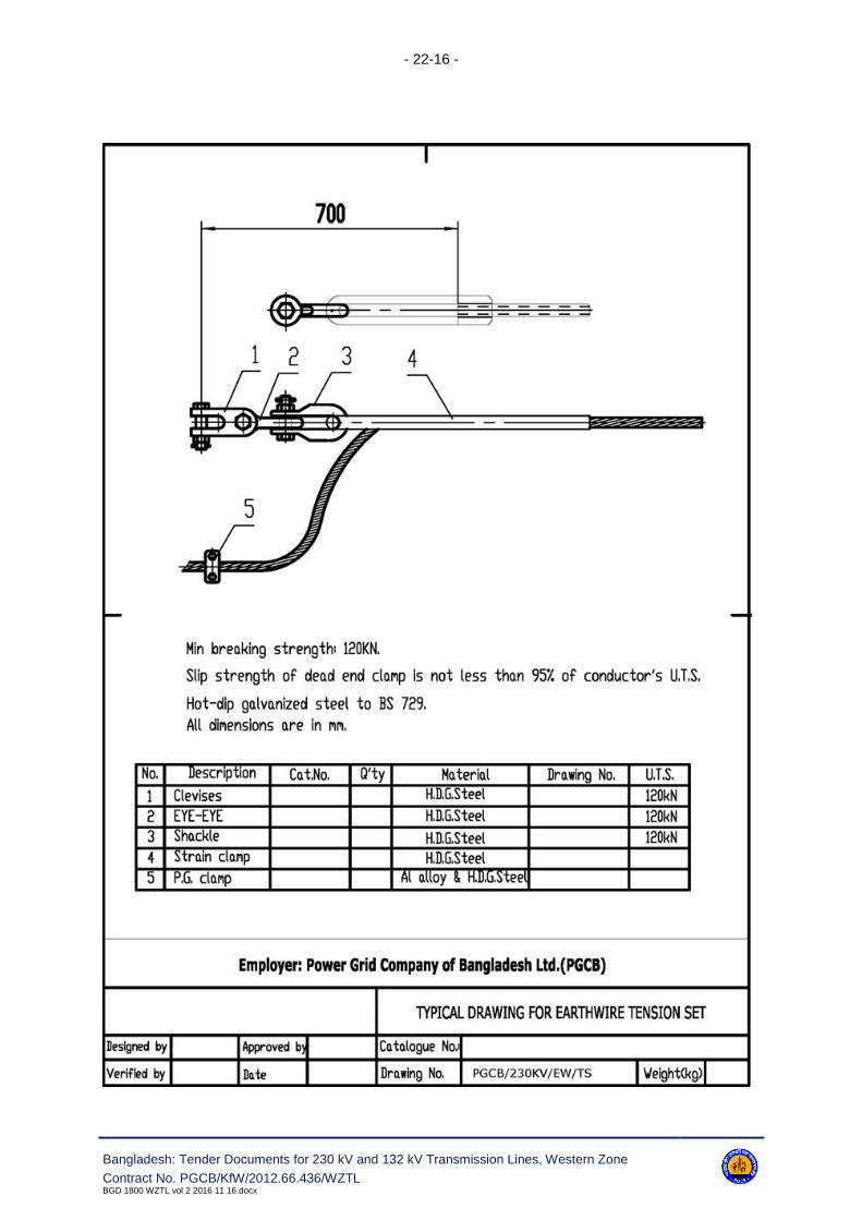
- 22-16 -
Bangladesh: Tender Documents for 230 kV and 132 kV Transmission Lines, Western Zone
Contract No. PGCB/KfW/2012.66.436/WZTLBGD 1800 WZTL vol 2 2016 11 16.docx

- 22-17 -
Bangladesh: Tender Documents for 230 kV and 132 kV Transmission Lines, Northern Zone; Contract No. PGCB/KfW/2012.66.436/WZTL
BGD 1800 WZTL vol 2 2016 11 16.docx

- 22-18 -
Bangladesh: Tender Documents for 230 kV and 132 kV Transmission Lines, Northern Zone; Contract No. PGCB/KfW/2012.66.436/WZTL
BGD 1800 WZTL vol 2 2016 11 16.docx

- 22-19 -
Bangladesh: Tender Documents for 230 kV and 132 kV Transmission Lines, Western Zone
Contract No. PGCB/KfW/2012.66.436/WZTLBGD 1800 WZTL vol 2 2016 11 16.docx
max 6500

- 22-20 -
Bangladesh: Tender Documents for 230 kV and 132 kV Transmission Lines, Western Zone
Contract No. PGCB/KfW/2012.66.436/WZTLBGD 1800 WZTL vol 2 2016 11 16.docx
22.4 230 & 132 kV Transmission Lines Insulators

- 22-21 -
Bangladesh: Tender Documents for 230 kV and 132 kV Transmission Lines, Western Zone
Contract No. PGCB/KfW/2012.66.436/WZTLBGD 1800 WZTL vol 2 2016 11 16.docx
22.5 230 & 132 kV Foundations & Earthing Arrangement

- 22-22 -
Bangladesh: Tender Documents for 230 kV and 132 kV Transmission Lines, Western Zone
Contract No. PGCB/KfW/2012.66.436/WZTLBGD 1800 WZTL vol 2 2016 11 16.docx

- 22-23 -
Bangladesh: Tender Documents for 230 kV and 132 kV Transmission Lines, Western Zone
Contract No. PGCB/KfW/2012.66.436/WZTLBGD 1800 WZTL vol 2 2016 11 16.docx

- 22-24 -
Bangladesh: Tender Documents for 230 kV and 132 kV Transmission Lines, Western Zone
Contract No. PGCB/KfW/2012.66.436/WZTLBGD 1800 WZTL vol 2 2016 11 16.docx
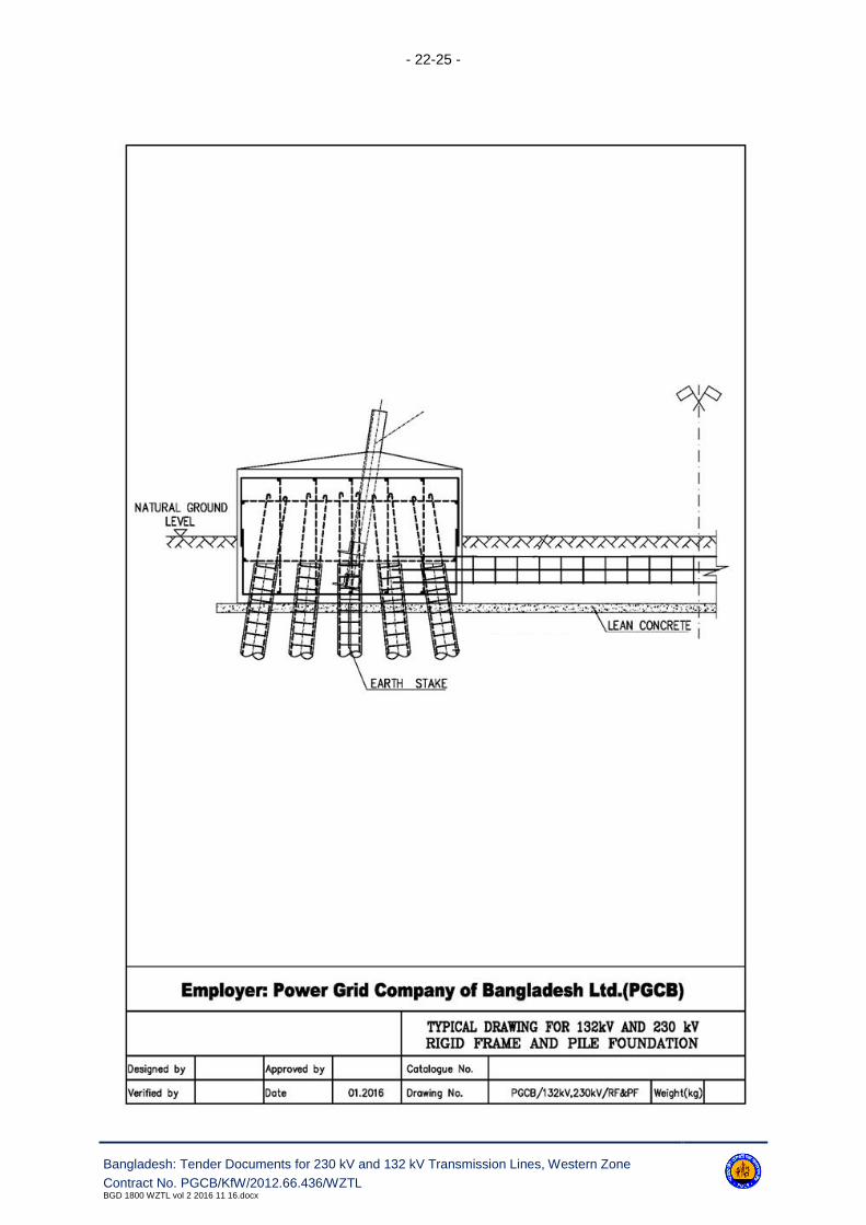
- 22-25 -
Bangladesh: Tender Documents for 230 kV and 132 kV Transmission Lines, Western Zone
Contract No. PGCB/KfW/2012.66.436/WZTLBGD 1800 WZTL vol 2 2016 11 16.docx

- 22-26 -
Bangladesh: Tender Documents for 230 kV and 132 kV Transmission Lines, Western Zone
Contract No. PGCB/KfW/2012.66.436/WZTLBGD 1800 WZTL vol 2 2016 11 16.docx

- 22-27 -
Bangladesh: Tender Documents for 230 kV and 132 kV Transmission Lines, Western Zone
Contract No. PGCB/KfW/2012.66.436/WZTLBGD 1800 WZTL vol 2 2016 11 16.docx

- 22-28 -
Bangladesh: Tender Documents for 230 kV and 132 kV Transmission Lines, Northern Zone; Contract No. PGCB/KfW/2012.66.436/WZTL
BGD 1800 WZTL vol 2 2016 11 16.docx
22.6 Common Drawings for 230 & 132 kV Transmission Lines

- 22-29 -
Bangladesh: Tender Documents for 230 kV and 132 kV Transmission Lines, Northern Zone; Contract No. PGCB/KfW/2012.66.436/WZTL
BGD 1800 WZTL vol 2 2016 11 16.docx
22.7 Common Drawings for 230 kV & 132 kV Transmission Lines

- 22-30 -
Bangladesh: Tender Documents for 230 kV and 132 kV Transmission Lines, Western Zone
Contract No. PGCB/KfW/2012.66.436/WZTLBGD 1800 WZTL vol 2 2016 11 16.docx

- 22-31 -
Bangladesh: Tender Documents for 230 kV and 132 kV Transmission Lines, Northern Zone; Contract No. PGCB/KfW/2012.66.436/WZTL
BGD 1800 WZTL vol 2 2016 11 16.docx

- 22-32 -
Bangladesh: Tender Documents for 230 kV and 132 kV Transmission Lines, Western Zone
Contract No. PGCB/KfW/2012.66.436/WZTLBGD 1800 WZTL vol 2 2016 11 16.docx
- 22-33 -
Bangladesh: Tender Documents for 230 kV and 132 kV Transmission Lines, Western Zone
Contract No. PGCB/KfW/2012.66.436/WZTLBGD 1800 WZTL vol 2 2016 11 16.docx

- 23-34 -
Bangladesh: Tender Documents for 230 kV and 132 kV Transmission Lines, Western Zone
Contract No. PGCB/KfW/2012.66.436/WZTLBGD 1800 WZTL vol 2 2016 11 16.docx
23. Reference Data
The following documents are enclosed for tender purposes and reference only.
1 Line route data
2 Soil investigation reports (soft copy on CD only)
3 Line survey reports (soft copy on CD only)
23.1 Line Route Data
All coordinates listed below as well as line route survey reports (soft copies) are indicative only and
meant to provide rough guideline and information on line routes.
23.2 Soil Investigation Report
The soil investigation report (soft copies) is indicative only and meant to provide rough guideline and
information on soil data on line routes.
During execution if the soil investigation results found different values than the enclosed one, the Con-
tractor has to do the works without any changed in the contract prices.
23.2.1 Line In / Line Out from the Jhenaidah 230/132/33 kV Substation to theExisting 132 kV Bheramara - Khulna South Double Circuit TransmissionLine - 2 x 1.5 km
23.2.2 Line In / Line Out from the Jhenaidah 230/132/33 kV Substation to the132-kV Jhenaidah - Jessore Double Circuit Transmission Line -2 x 0.5 km
23.2.3 132 kV Double Circuit Transmission Line Gallamari - Gopalganj - 53 km
23.2.4 Line In / Line Out from the Rajbari 132/33 kV Substation to the 132 kVBheramara - Faridpur Double Circuit Transmission Line - 2 x 2.0 km